EP3021814B1 - Systèmes et procédés de transfert de fluides à pression régulée - Google Patents
Systèmes et procédés de transfert de fluides à pression régulée Download PDFInfo
- Publication number
- EP3021814B1 EP3021814B1 EP14827069.7A EP14827069A EP3021814B1 EP 3021814 B1 EP3021814 B1 EP 3021814B1 EP 14827069 A EP14827069 A EP 14827069A EP 3021814 B1 EP3021814 B1 EP 3021814B1
- Authority
- EP
- European Patent Office
- Prior art keywords
- reservoir
- container
- passage
- fluid
- plunger
- Prior art date
- Legal status (The legal status is an assumption and is not a legal conclusion. Google has not performed a legal analysis and makes no representation as to the accuracy of the status listed.)
- Active
Links
Images





























Classifications
-
- A—HUMAN NECESSITIES
- A61—MEDICAL OR VETERINARY SCIENCE; HYGIENE
- A61J—CONTAINERS SPECIALLY ADAPTED FOR MEDICAL OR PHARMACEUTICAL PURPOSES; DEVICES OR METHODS SPECIALLY ADAPTED FOR BRINGING PHARMACEUTICAL PRODUCTS INTO PARTICULAR PHYSICAL OR ADMINISTERING FORMS; DEVICES FOR ADMINISTERING FOOD OR MEDICINES ORALLY; BABY COMFORTERS; DEVICES FOR RECEIVING SPITTLE
- A61J1/00—Containers specially adapted for medical or pharmaceutical purposes
- A61J1/14—Details; Accessories therefor
- A61J1/20—Arrangements for transferring or mixing fluids, e.g. from vial to syringe
- A61J1/22—Arrangements for transferring or mixing fluids, e.g. from vial to syringe with means for metering the amount of fluid
-
- A—HUMAN NECESSITIES
- A61—MEDICAL OR VETERINARY SCIENCE; HYGIENE
- A61J—CONTAINERS SPECIALLY ADAPTED FOR MEDICAL OR PHARMACEUTICAL PURPOSES; DEVICES OR METHODS SPECIALLY ADAPTED FOR BRINGING PHARMACEUTICAL PRODUCTS INTO PARTICULAR PHYSICAL OR ADMINISTERING FORMS; DEVICES FOR ADMINISTERING FOOD OR MEDICINES ORALLY; BABY COMFORTERS; DEVICES FOR RECEIVING SPITTLE
- A61J1/00—Containers specially adapted for medical or pharmaceutical purposes
- A61J1/14—Details; Accessories therefor
- A61J1/20—Arrangements for transferring or mixing fluids, e.g. from vial to syringe
-
- A—HUMAN NECESSITIES
- A61—MEDICAL OR VETERINARY SCIENCE; HYGIENE
- A61J—CONTAINERS SPECIALLY ADAPTED FOR MEDICAL OR PHARMACEUTICAL PURPOSES; DEVICES OR METHODS SPECIALLY ADAPTED FOR BRINGING PHARMACEUTICAL PRODUCTS INTO PARTICULAR PHYSICAL OR ADMINISTERING FORMS; DEVICES FOR ADMINISTERING FOOD OR MEDICINES ORALLY; BABY COMFORTERS; DEVICES FOR RECEIVING SPITTLE
- A61J1/00—Containers specially adapted for medical or pharmaceutical purposes
- A61J1/14—Details; Accessories therefor
- A61J1/20—Arrangements for transferring or mixing fluids, e.g. from vial to syringe
- A61J1/2003—Accessories used in combination with means for transfer or mixing of fluids, e.g. for activating fluid flow, separating fluids, filtering fluid or venting
- A61J1/2048—Connecting means
-
- A—HUMAN NECESSITIES
- A61—MEDICAL OR VETERINARY SCIENCE; HYGIENE
- A61J—CONTAINERS SPECIALLY ADAPTED FOR MEDICAL OR PHARMACEUTICAL PURPOSES; DEVICES OR METHODS SPECIALLY ADAPTED FOR BRINGING PHARMACEUTICAL PRODUCTS INTO PARTICULAR PHYSICAL OR ADMINISTERING FORMS; DEVICES FOR ADMINISTERING FOOD OR MEDICINES ORALLY; BABY COMFORTERS; DEVICES FOR RECEIVING SPITTLE
- A61J1/00—Containers specially adapted for medical or pharmaceutical purposes
- A61J1/14—Details; Accessories therefor
- A61J1/20—Arrangements for transferring or mixing fluids, e.g. from vial to syringe
- A61J1/2003—Accessories used in combination with means for transfer or mixing of fluids, e.g. for activating fluid flow, separating fluids, filtering fluid or venting
- A61J1/2068—Venting means
- A61J1/2072—Venting means for internal venting
-
- A—HUMAN NECESSITIES
- A61—MEDICAL OR VETERINARY SCIENCE; HYGIENE
- A61J—CONTAINERS SPECIALLY ADAPTED FOR MEDICAL OR PHARMACEUTICAL PURPOSES; DEVICES OR METHODS SPECIALLY ADAPTED FOR BRINGING PHARMACEUTICAL PRODUCTS INTO PARTICULAR PHYSICAL OR ADMINISTERING FORMS; DEVICES FOR ADMINISTERING FOOD OR MEDICINES ORALLY; BABY COMFORTERS; DEVICES FOR RECEIVING SPITTLE
- A61J1/00—Containers specially adapted for medical or pharmaceutical purposes
- A61J1/14—Details; Accessories therefor
- A61J1/20—Arrangements for transferring or mixing fluids, e.g. from vial to syringe
- A61J1/2096—Combination of a vial and a syringe for transferring or mixing their contents
-
- A—HUMAN NECESSITIES
- A61—MEDICAL OR VETERINARY SCIENCE; HYGIENE
- A61M—DEVICES FOR INTRODUCING MEDIA INTO, OR ONTO, THE BODY; DEVICES FOR TRANSDUCING BODY MEDIA OR FOR TAKING MEDIA FROM THE BODY; DEVICES FOR PRODUCING OR ENDING SLEEP OR STUPOR
- A61M5/00—Devices for bringing media into the body in a subcutaneous, intra-vascular or intramuscular way; Accessories therefor, e.g. filling or cleaning devices, arm-rests
- A61M5/14—Infusion devices, e.g. infusing by gravity; Blood infusion; Accessories therefor
- A61M5/162—Needle sets, i.e. connections by puncture between reservoir and tube ; Connections between reservoir and tube
-
- A—HUMAN NECESSITIES
- A61—MEDICAL OR VETERINARY SCIENCE; HYGIENE
- A61M—DEVICES FOR INTRODUCING MEDIA INTO, OR ONTO, THE BODY; DEVICES FOR TRANSDUCING BODY MEDIA OR FOR TAKING MEDIA FROM THE BODY; DEVICES FOR PRODUCING OR ENDING SLEEP OR STUPOR
- A61M5/00—Devices for bringing media into the body in a subcutaneous, intra-vascular or intramuscular way; Accessories therefor, e.g. filling or cleaning devices, arm-rests
- A61M5/178—Syringes
- A61M5/1782—Devices aiding filling of syringes in situ
-
- A—HUMAN NECESSITIES
- A61—MEDICAL OR VETERINARY SCIENCE; HYGIENE
- A61M—DEVICES FOR INTRODUCING MEDIA INTO, OR ONTO, THE BODY; DEVICES FOR TRANSDUCING BODY MEDIA OR FOR TAKING MEDIA FROM THE BODY; DEVICES FOR PRODUCING OR ENDING SLEEP OR STUPOR
- A61M5/00—Devices for bringing media into the body in a subcutaneous, intra-vascular or intramuscular way; Accessories therefor, e.g. filling or cleaning devices, arm-rests
- A61M5/178—Syringes
- A61M5/31—Details
- A61M5/3129—Syringe barrels
-
- A—HUMAN NECESSITIES
- A61—MEDICAL OR VETERINARY SCIENCE; HYGIENE
- A61M—DEVICES FOR INTRODUCING MEDIA INTO, OR ONTO, THE BODY; DEVICES FOR TRANSDUCING BODY MEDIA OR FOR TAKING MEDIA FROM THE BODY; DEVICES FOR PRODUCING OR ENDING SLEEP OR STUPOR
- A61M5/00—Devices for bringing media into the body in a subcutaneous, intra-vascular or intramuscular way; Accessories therefor, e.g. filling or cleaning devices, arm-rests
- A61M5/178—Syringes
- A61M5/31—Details
- A61M5/3145—Filters incorporated in syringes
-
- A—HUMAN NECESSITIES
- A61—MEDICAL OR VETERINARY SCIENCE; HYGIENE
- A61M—DEVICES FOR INTRODUCING MEDIA INTO, OR ONTO, THE BODY; DEVICES FOR TRANSDUCING BODY MEDIA OR FOR TAKING MEDIA FROM THE BODY; DEVICES FOR PRODUCING OR ENDING SLEEP OR STUPOR
- A61M5/00—Devices for bringing media into the body in a subcutaneous, intra-vascular or intramuscular way; Accessories therefor, e.g. filling or cleaning devices, arm-rests
- A61M5/178—Syringes
- A61M5/31—Details
- A61M5/315—Pistons; Piston-rods; Guiding, blocking or restricting the movement of the rod or piston; Appliances on the rod for facilitating dosing ; Dosing mechanisms
- A61M5/31511—Piston or piston-rod constructions, e.g. connection of piston with piston-rod
- A61M5/31513—Piston constructions to improve sealing or sliding
-
- A—HUMAN NECESSITIES
- A61—MEDICAL OR VETERINARY SCIENCE; HYGIENE
- A61M—DEVICES FOR INTRODUCING MEDIA INTO, OR ONTO, THE BODY; DEVICES FOR TRANSDUCING BODY MEDIA OR FOR TAKING MEDIA FROM THE BODY; DEVICES FOR PRODUCING OR ENDING SLEEP OR STUPOR
- A61M5/00—Devices for bringing media into the body in a subcutaneous, intra-vascular or intramuscular way; Accessories therefor, e.g. filling or cleaning devices, arm-rests
- A61M5/178—Syringes
- A61M5/31—Details
- A61M5/32—Needles; Details of needles pertaining to their connection with syringe or hub; Accessories for bringing the needle into, or holding the needle on, the body; Devices for protection of needles
- A61M5/3295—Multiple needle devices, e.g. a plurality of needles arranged coaxially or in parallel
- A61M5/3298—Needles arranged in parallel
-
- A—HUMAN NECESSITIES
- A61—MEDICAL OR VETERINARY SCIENCE; HYGIENE
- A61M—DEVICES FOR INTRODUCING MEDIA INTO, OR ONTO, THE BODY; DEVICES FOR TRANSDUCING BODY MEDIA OR FOR TAKING MEDIA FROM THE BODY; DEVICES FOR PRODUCING OR ENDING SLEEP OR STUPOR
- A61M5/00—Devices for bringing media into the body in a subcutaneous, intra-vascular or intramuscular way; Accessories therefor, e.g. filling or cleaning devices, arm-rests
- A61M5/14—Infusion devices, e.g. infusing by gravity; Blood infusion; Accessories therefor
- A61M5/162—Needle sets, i.e. connections by puncture between reservoir and tube ; Connections between reservoir and tube
- A61M2005/1623—Details of air intake
-
- A—HUMAN NECESSITIES
- A61—MEDICAL OR VETERINARY SCIENCE; HYGIENE
- A61M—DEVICES FOR INTRODUCING MEDIA INTO, OR ONTO, THE BODY; DEVICES FOR TRANSDUCING BODY MEDIA OR FOR TAKING MEDIA FROM THE BODY; DEVICES FOR PRODUCING OR ENDING SLEEP OR STUPOR
- A61M5/00—Devices for bringing media into the body in a subcutaneous, intra-vascular or intramuscular way; Accessories therefor, e.g. filling or cleaning devices, arm-rests
- A61M5/178—Syringes
- A61M2005/1787—Syringes for sequential delivery of fluids, e.g. first medicament and then flushing liquid
-
- A—HUMAN NECESSITIES
- A61—MEDICAL OR VETERINARY SCIENCE; HYGIENE
- A61M—DEVICES FOR INTRODUCING MEDIA INTO, OR ONTO, THE BODY; DEVICES FOR TRANSDUCING BODY MEDIA OR FOR TAKING MEDIA FROM THE BODY; DEVICES FOR PRODUCING OR ENDING SLEEP OR STUPOR
- A61M5/00—Devices for bringing media into the body in a subcutaneous, intra-vascular or intramuscular way; Accessories therefor, e.g. filling or cleaning devices, arm-rests
- A61M5/178—Syringes
- A61M5/31—Details
- A61M2005/3114—Filling or refilling
-
- A—HUMAN NECESSITIES
- A61—MEDICAL OR VETERINARY SCIENCE; HYGIENE
- A61M—DEVICES FOR INTRODUCING MEDIA INTO, OR ONTO, THE BODY; DEVICES FOR TRANSDUCING BODY MEDIA OR FOR TAKING MEDIA FROM THE BODY; DEVICES FOR PRODUCING OR ENDING SLEEP OR STUPOR
- A61M5/00—Devices for bringing media into the body in a subcutaneous, intra-vascular or intramuscular way; Accessories therefor, e.g. filling or cleaning devices, arm-rests
- A61M5/178—Syringes
- A61M5/31—Details
- A61M2005/3123—Details having air entrapping or venting means, e.g. purging channels in pistons
-
- A—HUMAN NECESSITIES
- A61—MEDICAL OR VETERINARY SCIENCE; HYGIENE
- A61M—DEVICES FOR INTRODUCING MEDIA INTO, OR ONTO, THE BODY; DEVICES FOR TRANSDUCING BODY MEDIA OR FOR TAKING MEDIA FROM THE BODY; DEVICES FOR PRODUCING OR ENDING SLEEP OR STUPOR
- A61M5/00—Devices for bringing media into the body in a subcutaneous, intra-vascular or intramuscular way; Accessories therefor, e.g. filling or cleaning devices, arm-rests
- A61M5/178—Syringes
- A61M5/31—Details
- A61M2005/3128—Incorporating one-way valves, e.g. pressure-relief or non-return valves
-
- A—HUMAN NECESSITIES
- A61—MEDICAL OR VETERINARY SCIENCE; HYGIENE
- A61M—DEVICES FOR INTRODUCING MEDIA INTO, OR ONTO, THE BODY; DEVICES FOR TRANSDUCING BODY MEDIA OR FOR TAKING MEDIA FROM THE BODY; DEVICES FOR PRODUCING OR ENDING SLEEP OR STUPOR
- A61M5/00—Devices for bringing media into the body in a subcutaneous, intra-vascular or intramuscular way; Accessories therefor, e.g. filling or cleaning devices, arm-rests
- A61M5/178—Syringes
- A61M5/31—Details
- A61M5/3129—Syringe barrels
- A61M2005/3132—Syringe barrels having flow passages for injection agents at the distal end of the barrel to bypass a sealing stopper after its displacement to this end due to internal pressure increase
-
- A—HUMAN NECESSITIES
- A61—MEDICAL OR VETERINARY SCIENCE; HYGIENE
- A61M—DEVICES FOR INTRODUCING MEDIA INTO, OR ONTO, THE BODY; DEVICES FOR TRANSDUCING BODY MEDIA OR FOR TAKING MEDIA FROM THE BODY; DEVICES FOR PRODUCING OR ENDING SLEEP OR STUPOR
- A61M5/00—Devices for bringing media into the body in a subcutaneous, intra-vascular or intramuscular way; Accessories therefor, e.g. filling or cleaning devices, arm-rests
- A61M5/178—Syringes
- A61M5/31—Details
- A61M5/315—Pistons; Piston-rods; Guiding, blocking or restricting the movement of the rod or piston; Appliances on the rod for facilitating dosing ; Dosing mechanisms
- A61M5/31596—Pistons; Piston-rods; Guiding, blocking or restricting the movement of the rod or piston; Appliances on the rod for facilitating dosing ; Dosing mechanisms comprising means for injection of two or more media, e.g. by mixing
- A61M2005/31598—Pistons; Piston-rods; Guiding, blocking or restricting the movement of the rod or piston; Appliances on the rod for facilitating dosing ; Dosing mechanisms comprising means for injection of two or more media, e.g. by mixing having multiple telescopically sliding coaxial pistons encompassing volumes for components to be mixed
-
- A—HUMAN NECESSITIES
- A61—MEDICAL OR VETERINARY SCIENCE; HYGIENE
- A61M—DEVICES FOR INTRODUCING MEDIA INTO, OR ONTO, THE BODY; DEVICES FOR TRANSDUCING BODY MEDIA OR FOR TAKING MEDIA FROM THE BODY; DEVICES FOR PRODUCING OR ENDING SLEEP OR STUPOR
- A61M2205/00—General characteristics of the apparatus
- A61M2205/75—General characteristics of the apparatus with filters
Definitions
- Certain embodiments disclosed herein relate to pressure-regulating systems for coupling with medicinal containers (e.g., vials and/or bags), and components thereof, and methods to contain vapors and/or to aid in regulating pressures within medicinal containers. Some embodiments relate to pressure-regulating syringe assemblies.
- US20120046636A1 describes a method for allegedly contamination-free transfer of liquid from one container to another, and devices to carry out the method.
- US '636 states that contamination-free transfer means that during the transfer process there is no leakage of the liquid and air contaminated by the liquid, and vapor from the liquid to the surroundings, and surrounding contaminants from outside the containers that contact the liquid.
- the fluid transfer apparatus of US '636 comprises a syringe-like proximal section which includes a cylindrical body, a tubular throat, a separating element that prevents the passage of fluids between the connector section and the throat, and a piston that is displaceable within the cylindrical body, the piston defining a distal liquid chamber and a proximal gas chamber, both of variable volume.
- a syringe assembly can be configured to couple to the adapter assembly without requiring a specific rotational orientation of the syringe assembly relative to the adapter assembly.
- introducing a piercing member of a vial adapter through the septum of a vial can cause the pressure within the vial to rise (or fall, in some cases).
- This pressure increase can cause fluid to leak from the vial at the interface of the septum and piercing member or at the attachment interface of the adapter and a medical device, such as a syringe.
- a medical device such as a syringe.
- pressure differences can cause an amount of fluid to spurt from the syringe or the vial.
- introducing a fluid into the vial can cause the pressure to rise in the vial.
- a solvent such as sterile saline
- Such introduction of fluid into the vial can cause the pressure in the vial to rise above the pressure of the surrounding environment, which can result in fluid leaking from the vial at the interface of the septum and piercing member or at the attachment interface of the adapter and a medical device, such as a syringe.
- the increased pressure in the vial can make it difficult to introduce an accurate amount of the fluid into the vial with a syringe, or other medical instrument. Also, should the syringe be decoupled from the vial when the pressure inside the vial is greater than the surrounding pressure (e.g., atmospheric), the pressure gradient can cause a portion of the fluid to spurt from the vial.
- the surrounding pressure e.g., atmospheric
- the regulator 30 can have a filter.
- the filter can selectively inhibit passage of fluids, gases, liquids, and/or contaminants between the valve 25 and the reservoir 50 or the ambient surroundings.
- the filter can selectively inhibit passage of fluids, gases, liquids and/or contaminants between the reservoir 50 and the valve 25 and/or between the ambient surroundings and the valve 25.
- Figure 6 illustrates an embodiment of a system 100 comprising a vial 110, an accessor 120, and a regulator 130.
- the vial 110 includes a body 112 and a cap 114.
- the vial 110 contains a medical fluid 116 and a relatively small amount of sterilized air 118.
- the fluid 116 is removed from the vial 110 when the vial 110 is oriented with the cap 114 facing downward (e.g., the cap 114 is between the fluid and the floor).
- the accessor 120 includes a conduit 122 fluidly connected at one end to an exchange device 140, such as a syringe 142 with a plunger 144.
- the conduit 122 extends through the cap 114 and into the fluid 116.
- the regulator 130 can include a reservoir 132 and a conduit 134.
- the reservoir 132 can be a chamber, such as a bag, or a cavity with a piston movable relative to the cavity.
- the reservoir 132 can be located at least partially inside of a rigid enclosure 124.
- the reservoir 132 and the conduit 134 are in fluid communication with a reservoir interior 150, which includes an amount of cleaned and/or sterilized air.
- the reservoir 132 has a bag.
- the reservoir 132 has one or more rigid walls and at least one movable wall 136. At least some of the outside surface of the reservoir 132 can be in contact with the ambient air surrounding the system 100. For example, an outside surface of the moveable wall 136 can be in contact with the ambient air.
- the reservoir 132 can be substantially impervious such that the fluid 116, the air 118 inside the vial 110, and the reservoir interior 150 do not contact the ambient air.
- the plunger 144 can be withdrawn to fill a portion of the syringe 142 with the fluid 116. Withdrawing the plunger 144 can increase the effective volume inside the syringe 142, thereby decreasing the pressure inside the syringe 142. Such a decrease of pressure within the syringe 142 increases the difference in pressure between the inside of the vial 110 and the inside of the syringe 142, which causes the fluid 116 to flow into the syringe 142. As the fluid 116 flows from the vial 110 to the syringe 142, the pressure inside the vial 110 drops below the pressure of the reservoir interior 150, which causes at least a portion of the reservoir interior 150 to flow into the vial 110.
- the pressure differential necessary to cause flow depends on the viscosity of the flow liquid (or gas) and the geometry of the structures through which the fluid flows. Some embodiments are optimized to reduce flow resistance.
- the decrease of pressure within the vial 110 increases the difference in pressure between the interior and exterior of the reservoir 132, which causes the reservoir 132 to decrease in internal volume or contract, which in turn encourages an amount of regulatory fluid through the conduit 134 and into the vial 110.
- the reservoir 132 contracts outside the vial 110 to a new volume that compensates for the volume of the fluid 116 withdrawn from the vial 110.
- the plunger 144 ceases being withdrawn from the vial 110, the system is again in equilibrium.
- withdrawal of the fluid 116 can be facilitated.
- the plunger 144 remains at the position to which it has been withdrawn, thereby allowing removal of an accurate amount of the fluid 116 from the vial 110.
- the decreased volume of the reservoir 132 is approximately equal to the volume of liquid removed from the vial 110. In some arrangements, the volume of the reservoir 132 decreases at a slower rate as greater amounts of fluid are withdrawn from the vial 110 such that the volume of fluid withdrawn from the vial 110 is greater than the decreased volume of the reservoir 132.
- the reservoir 132 can be substantially and/or completely collapsed or deflated, such that there is substantially no volume inside the reservoir 132.
- the piston can traverse so as to substantially abut the front wall, thereby collapsing the reservoir 132 and providing substantially no volume inside.
- collapsing of the reservoir 132 prevents the reservoir 132 from allowing the pressure inside the vial 110 to reach ambient pressure.
- such collapsing of the reservoir 132 creates substantially no restoring force that tends to create a pressure differential between the inside of the reservoir 132 and the inside of the vial 110, such as when the reservoir 132 is generally non-resilient, rigid, or completely rigid.
- the syringe 142 has fluid contents 143.
- a portion of the fluid contents 143 can be introduced into the vial 110 by depressing the plunger 144 (toward the vial), which can be desirable in certain instances.
- more of the fluid 116 than desired initially might be withdrawn inadvertently.
- some of the air 118 in the vial 110 initially initially might be withdrawn, creating unwanted bubbles within the syringe 142. It may thus be desirable to inject some of the withdrawn fluid 116 and/or air 118 back into the vial 110.
- Depressing the plunger 144 encourages the fluid contents 143 of the syringe into the vial 110, which decreases the effective volume of the vial 110, thereby increasing the pressure within the vial 110.
- An increase of pressure within the vial 110 increases the difference in pressure between the inside of the vial 110 and the inside of the reservoir 132, which can cause the air 118 to flow into the reservoir 132, which in turn causes the reservoir 132 to expand.
- the reservoir 132 expands or increases to a new volume that compensates for the volume of the contents 143 of the syringe 142 introduced into the vial 110.
- the plunger 144 As the system 100 operates near equilibrium, introduction of the contents 143 can be facilitated. Moreover, due to the equilibrium of the system 100, the plunger 144 generally remains at the position to which it is depressed, thereby allowing introduction of an accurate amount of the contents 143 of the syringe 142 into the vial 110.
- the plunger 144 may move inadvertently if the pressure differential is large enough to overcome frictional forces.
- temporary pressure differentials are used to prevent fluid from dripping out of, for example, a syringe after it is disconnected from a vial. For example, a portion of the syringe can increase in effective volume, thereby reducing the local pressure and drawing at least some fluid into that region of added volume. Some embodiments, however, minimize temporary pressure differentials.
- the increased volume of the reservoir 132 is approximately equal to the volume of air 118 removed from the vial 110. In some arrangements, the volume of the reservoir 132 increases at a slower rate as greater amounts of the contents 143 are introduced into the vial 110, such that the volume of the contents 143 introduced into the vial 110 is greater than the increased volume of the reservoir 132.
- the reservoir 132 can stretch, expand, or otherwise increase in volume to expand beyond a resting volume. In some instances, the expansion gives rise to a restorative force that effectively creates a difference in pressure between the inside of the reservoir 132 and the inside of the vial 110. For example, a slight overpressure (relative to ambient) inside the vial 110 can be created when the reservoir 132 is stretched or expanded.
- components described herein can be molded as individual components and/or can be integrated with other molded components. For example, in some cases, multiple components can be molded at the same time in a single molding press. Some of the components can be injection molded with medical-grade plastic. Some components are made from acrylic plastic, ABS plastic, or polycarbonate plastic. Some components can be made from metal, such as stainless steel. Many of the metal components can be machined with a computer numerical control (“CNC") mill.
- CNC computer numerical control
- Expandable reservoirs such as some bags, can be configured to unfold, unroll, expand, contract, inflate, deflate, compress, and/or decompress.
- Reservoirs can include any of a wide variety of flexible and/or expandable materials (although some reservoirs are inflexible and rigid).
- reservoirs or bags include polyester, polyethylene, polypropylene, saran, latex rubber, polyisoprene, silicone rubber, vinyl, polyurethane, or other materials.
- reservoirs or bags include a material having a metal component to further inhibit fluid (including gas or air) leakage through the material of the bag, e.g., metalized biaxially-oriented polyethylene terephthalate (also known as "PET" and available under the trade name Mylar ® ).
- reservoirs and bags include a laminate.
- Reservoirs and bags can include a metal material.
- reservoirs and bags can be constructed of a layer of 0.36 Mil (7.8#) metalized (e.g., aluminum) PET film and a layer of 0.65 Mil (9.4#) linear low-density polyethylene.
- reservoirs or bags include a material capable of forming a substantially airtight seal with a coupling.
- the reservoir includes a coating.
- the reservoir includes a coating that reduces its porosity.
- the coating is evaporated aluminum or gold.
- the coating includes a water soluble plastic configured to form a barrier to inhibit passage of gases.
- the coating is applied to the outside of the reservoir. In other instances, the coating is applied to the inside of the reservoir. In some cases, the coating is applied to the inside and the outside of the reservoir. In some embodiments, the coating is a polyolefin.
- Vials can include any suitable container for storing medical fluids.
- the vials can be any of a number of standard medical vials known in the art, such as those produced by Abbott Laboratories of Abbott Park, Illinois.
- vials are capable of being hermetically sealed.
- the vial has a body and a cap.
- the body can be a rigid, substantially impervious material, such as plastic or glass.
- the cap includes a septum and a casing.
- the septum can be an elastomeric material capable of deforming in such a way when punctured by an item that it forms a substantially airtight seal around that item.
- the septum includes silicone rubber or butyl rubber.
- a filler is located inside a reservoir such as a bag.
- the diameter and thickness of the filler are about the same as the diameter D and thickness T of the bag.
- a filler is configured to contain a volume of gas, such as sterilized air.
- the filler is porous.
- the filler is a sponge or sponge-like material.
- the filler includes cotton wadding.
- the filler includes a mat of regularly or randomly arranged fibers configured to provide a network of chambers or spaces therein.
- the filler is made of low density foam.
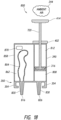
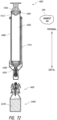
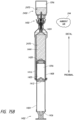
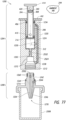
- Figure 7 schematically illustrates an embodiment of a pressure regulating syringe system 200 coupled to a container 204, such as a vial.
- the container 204 can be configured to hold a drug, a pharmaceutical, and/or a substance used in medical care.
- the regulating system 200 can include a first reservoir 208 and a second reservoir 212.
- the first reservoir 208 and the second reservoir 212 can be configured to change in volume (e.g., individually and/or together).
- the first reservoir 208 is configured to store a gas, which can be sterilized air, unsterilized air, or any gas.
- the second reservoir 212 is configured to store a liquid, which can be a medicinal fluid, any fluid that contains a pharmaceutical agent, a liquid that will be injected into the container 204, water, a saline solution, or any liquid.
- the first reservoir 208 and the second reservoir 212 can be located in a housing, which can include a barrel and/or a plunger.
- the housing can be substantially rigid with low brittleness to avoid cracking.
- the housing is made from molded plastic. The plastic can be clear and/or translucent.
- the first reservoir and the second reservoir may be configured so that, during use, fluid does not pass directly between the first reservoir and the second reservoir (e.g., directly from the first reservoir to the second reservoir, or directly from the second reservoir to the first reservoir).
- the first reservoir 208 and/or the second reservoir includes a bag with an internal volume.
- the internal volume can increase or decrease.
- the first reservoir 208 and/or the second reservoir has a rigid outer housing that can be made from plastic. The rigid outer housing can be somewhat flexible if enough force or pressure is placed on the outer housing.
- certain embodiments include a dividing member, such as a seal 216.
- the seal 216 can be located between the first reservoir 208 and the second reservoir 212.
- the seal 216 can isolate (e.g., fluidly isolate) the first reservoir 208 from the second reservoir 212 such that a liquid or gas located inside the first reservoir 208 is inhibited or prevented from flowing through the area that the seal 216 blocks to the second reservoir 212, and such that a liquid or gas located inside the second reservoir 212 is inhibited or prevented from flowing through the area that the seal 216 blocks to the first reservoir 208.
- the seal is a rubber plunger seal or a rubber O-ring.
- Some embodiments include a second passage 224 (e.g., passageway, channel, lumen, or otherwise).
- the second passage 224 can fluidly couple the second reservoir 212 to the container 204, such that fluid and/or gas from the second reservoir 212 can flow into the container 204 and/or such that fluid and/or gas from the container 204 can flow into the second reservoir 212.
- the first passage 220 and the second passage 224 can include lumens, channels, open areas, or any other structure capable of forming passages that can hold or communicate fluids, liquids, and/or gases.
- the first passage 220 is called a "regulating channel” and the second passage 224 is called an "access channel” or "extraction channel.”
- the second passage 224 is an extractor channel configured to communicate liquid, medicinal liquid, medical liquid, therapeutic fluid, and/or saline. In some embodiments, the second passage 224 is configured to communicate gas, sterilized gas, and/or air. In some embodiments, the first passage 220 is a regulator channel configured to regulate pressure in the container 204. In some embodiments, the first passage 220 is configured to communicate gas, sterilized gas, and/or air. In some embodiments, the first passage 220 is configured to communicate liquid, medicinal liquid, medical liquid, therapeutic fluid, and/or saline. In some embodiments, the first passage 220 and/or the second passage 224 are configured to communicate powder, such as a medical powder.
- some embodiments include a first flow controller 228.
- the first flow controller 228 When in an open position, the first flow controller 228 allows fluid to flow through the first passage 220. When in a closed position, the first flow controller 228 inhibits or prevents fluid from flowing through the first passage 220.
- Certain embodiments have a second flow controller 232. When the second flow controller 232 is in an open position fluid can flow through the second passage 224. When the second flow controller 232 is in a closed position fluid is inhibited or prevented from flowing through the second passage 224.
- the first flow controller 228 and the second flow controller 232 are one flow controller, such that one flow controller is capable of controlling the flow of liquids and/or gases in the first passage 220 and in the second passage 224.
- the first passage 220 can be located outside of the first reservoir 208 and the second reservoir 212.
- the first reservoir 208 can have a central axis that runs generally parallel to a longitudinal axis of the system 200.
- the first passage 220 and/or a portion of the first passage 220 can be located radially outward from the central axis of the first reservoir 208.
- the first passage can be located radially outside of the first reservoir 208 rather than being located inside the outer perimeter of the first reservoir 208.
- the pressure regulator 240 can be configured to reduce and/or eliminate the pressure differential between the pressure of ambient air 244 (located outside of the pressure regulating syringe system 200) and the pressure inside the first reservoir 208.
- the pressure regulator 240 can equalize the pressure between the inside of the first reservoir 208 and ambient air 244 (e.g., the pressure regulator 240 can be a pressure equalizer in some embodiments).
- friction or cracking pressure can inhibit the pressure regulator 240 from equalizing the pressure between the ambient air 244 and the first reservoir 208.
- the pressure regulator 240 can be lubricated (e.g., with a medical-grade lubricant) to reduce friction and/or cracking pressure to increase the equalization ability of the pressure regulator 240.
- the pressure regulator 240 can be a component that changes the effective volume of the first reservoir 208.
- the pressure regulator 240 is a bag.
- the first reservoir 208 has an open end that is sealed by a rubber plunger and the pressure regulator 240 includes the rubber plunger that slides inside the first reservoir 208 to change the effective internal volume of the first reservoir 208.
- the pressure regulator 240 can be a component that allows ambient air 244 to flow into or out of the first reservoir 208.
- the pressure regulator 240 can include a valve (e.g., opened by a pressure differential) or a hole that can be covered by a cap.
- the ambient air 244 is represented by a cloud with a dashed box that surrounds the pressure regulating syringe system 200. This shows that the ambient air 244 typically surrounds the pressure regulating syringe system 200. Many other figures illustrated herein include ambient air that surrounds the embodiments, but many figures do not include a dashed box in the interest of providing a clear view of other items. Ambient air is typically located outside of pressure regulating syringe systems and typically surrounds pressure regulating syringe systems.
- a coupling system 250 to fluidly and/or mechanically couple the pressure regulating system 200 to a container 204, which can be a vial, a glass container, a rigid plastic container, a flexible plastic container, any container used in intravenous infusion, or any other container.
- the first flow controller 228 and the second flow controller 232 are part of the coupling system 250.
- the first flow controller 228 and/or the second flow controller 232 move from a closed position to an open position.
- the first reservoir 208 and the second reservoir 212 are part of a closed system that is fluidly isolated from the ambient air 244.
- a closed system can help prevent and/or limit the amount of pharmaceutical agents released by the pressure regulating syringe system 200 into the ambient air 244.
- the pressure regulating syringe system 200 can be configured to prevent liquids and gases that have been contaminated with pharmaceuticals from the container 204 from exiting the pressure regulating syringe system 200.
- the first flow controller 228 and the second flow controller 232 can be configured to prevent and/or limit the escape of gases and liquids from the first reservoir 208 and/or the second reservoir 212 after the pressure regulating syringe system 200 has been decoupled from the container 204.
- the first reservoir 208 and the second reservoir 212 are located outside of the container 204, which can be a vial.
- the first reservoir 208 and the second reservoir 212 can be integrated inside of a syringe and/or located inside of a syringe.
- the first reservoir 208 is located inside of a plunger of a syringe and the second reservoir is located inside of a barrel of a syringe.
- the barrel can be a housing in which a plunger can slide.
- the plunger can form some of the outer walls of the first reservoir 208.
- the plunger can form one or more walls of the second reservoir 212.
- the barrel can form some of the outer walls of the second reservoir 212.
- the container 304 can include a septum 370 in the neck 358 and/or lip 362 that is configured to prevent inadvertent transmission of gas or liquid.
- the septum 370 can prevent ambient air 244 from inadvertently entering the container 304 and can prevent gas or liquid located inside the container 304 from inadvertently escaping the container.
- a first passage 320 and a second passage 324 can pass through (or pierce) the septum 370, and thus, can transmit gas and fluid into and/or out of the container 304.
- a portion of the first passage 320 configured to pass through the septum 370 can be located in a first piercing member 374.
- a portion of the second passage 324 configured to pass through the septum 370 can be located in a second piercing member 378.
- the first piercing member 374 and the second piercing member 378 are part of a single piercing member.
- the piercing member can be a plastic lance that includes a portion of the first passage 320 and a portion of the second passage 324.
- the lance has a pointed distal tip.
- the lance has a generally rounded distal tip.
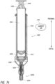
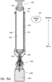
- a distal plunger seal 316 can be coupled to the distal end of the plunger 394.
- the volume of the second reservoir 312 is the internal space of the barrel 390 up to the distal plunger seal 316.
- the syringe system 300 can be configured such that pushing the plunger 394 in a distal direction (e.g., towards the container 304) reduces the volume of the second reservoir 312.
- the distal plunger seal 316 can be a dual wiper seal, which can be made from rubber. Pushing the plunger 394 in a distal direction can cause gas or liquid located inside the second reservoir 312 to flow through the second passage 324 and into the container 304.
- the plunger 394 has an internal volume of at least about 40 milliliters and/or less than or equal to about 100 milliliters; at least about 10 milliliters and/or less than or equal to about 300 milliliters; or at least about 55 milliliters and/or less than or equal to about 85 milliliters.
- the first reservoir 308 (which can be a gas reservoir) has an internal volume and/or a maximum internal volume of at least about 40 milliliters and/or less than or equal to about 100 milliliters; at least about 10 milliliters and/or less than or equal to about 500 milliliters; or at least about 55 milliliters and/or less than or equal to about 85 milliliters.
- the barrel 390 has an internal volume of at least about 40 milliliters and/or less than or equal to about 100 milliliters; at least about 10 milliliters and/or less than or equal to about 300 milliliters; or at least about 55 milliliters and/or less than or equal to about 85 milliliters.
- the second reservoir 312 (which can be configured to hold a liquid) has an internal volume and/or a maximum internal volume of at least about 40 milliliters and/or less than or equal to about 100 milliliters; at least about 10 milliliters and/or less than or equal to about 500 milliliters; or at least about 55 milliliters and/or less than or equal to about 85 milliliters.
- the second reservoir 312 has a capacity of greater than or equal to about 60 milliliters and the first reservoir 308 has a capacity of greater than or equal to 70 milliliters.
- the first reservoir 308 can have a maximum capacity that is larger than the maximum capacity of the second reservoir 312.
- the first reservoir 308 contains sterilized gas, such as sterilized air.
- the first reservoir 308 can be fluidly isolated (e.g., sealed) from the ambient air 244 such that the pressure regulating syringe system 300 prevents and/or hinders gas exchange between the first reservoir 308 and the ambient air 244.
- the second reservoir 312 can be configured to hold a pharmaceutical substance.
- the volume of the first reservoir 308 is the volume inside the plunger 394 from the distal plunger seal 316 to a proximal plunger seal 340.
- the distal plunger seal 316 can separate the first reservoir 308 from the second reservoir 312.
- the proximal plunger seal 340 can be a dual wiper seal, which can be made from rubber.
- the first reservoir 308 can in fluid communication with the first passage 320.
- gas or other fluids located inside the first reservoir 308 can flow between the first reservoir 308 and the inside of the container 304. Gas or fluids can flow from the container 304 to the first reservoir 308.
- Some embodiments include one-way valves to block flow from the container 304 to the first reservoir 308 or to block flow from the first reservoir 308 to the container 304.
- the first reservoir 308 is in fluid communication with an internal portion of the container 304.
- the proximal plunger seal 340 can be located in a plunger 394 and can be slidably coupled inside of the plunger 394.
- the proximal plunger seal 340 can separate a distal gas reservoir from a proximal gas reservoir.
- the distal gas reservoir can be located on the distal side of the proximal plunger seal 340 and the proximal gas reservoir can be located on the proximal side of the proximal plunger seal 340.
- the proximal gas reservoir can include a part of the surrounding ambient air.
- the proximal plunger seal 340 can seal against an inner diameter of the plunger 394.
- the plunger 394 can be slidably coupled to a barrel 390.
- some embodiments include a second reservoir 312.
- the second reservoir 312 can be configured to hold a liquid.
- the second reservoir 312 can be located distally relative to the distal gas reservoir of the plunger and/or distally relative to the distal plunger seal 316.
- the second reservoir 312 can be located inside of the barrel 390.
- the second reservoir 312 is a volume bounded by the barrel 390, the distal plunger seal 316, and a distal wall of the syringe assembly 301.
- syringe systems have an area 398 between the barrel 390 and the plunger 394. This area can be located radially outward from the plunger 394 and radially inward from the barrel 390.
- a proximal seal 406, such as an O-ring, can inhibit or prevent gas or liquid from escaping from the area 398 to the ambient air 244. In some embodiments, the proximal seal 406 can be located near the barrel's finger grips 402.
- the proximal end of the first passage 320 can be located near the barrel's finger grips 402; at least about 0.01 centimeters and/or less than or equal to about 1 centimeter from the barrel's finger grips 402; or at least about 0.1 centimeters and/or less than or equal to about 4 centimeters from the barrel's finger grips 402.
- Air or gas located inside the first reservoir 308 can flow through a hole 410 in the first reservoir 308 (e.g., a hole in the plunger 394), through the area 398, and into the proximal end of the first passage 320.
- gas or liquid flowing through the area 398 travels in one direction while gas flowing through the first passage 320 flows in an opposite direction.
- the area 398 can bound a passage between a portion of the barrel 390 and a portion of the plunger 394.
- the passage that the area 398 bounds can be oriented substantially parallel to a portion of the first passage 320.
- a portion of the first passage 320 can be located radially outward relative to the area 398.
- a portion of the first passage 320 can be located radially outward from and/or outside of the plunger 394, the first reservoir 308, the second reservoir 312, and/or the barrel 390.
- a portion of the first passage is located inside of the plunger 394 rather than being located radially outward from the plunger 394.
- the plunger 394 can have finger grips 414.
- a user can pull the plunger's finger grips 414 proximally (e.g., away from the barrel's finger grips 402), thereby increasing the volume of the second reservoir 312 and extracting liquid from inside of the container 304 and into the second reservoir 312 via the second passage 324. Extracting liquid from inside the container 304 can cause pressure inside the container 304 to drop below ambient pressure (e.g., the pressure of the environment outside of the syringe system 300).
- ambient pressure e.g., the pressure of the environment outside of the syringe system 300.
- gas inside the first reservoir 308 can flow into the first passage 320 and then into the container 304 to increase the pressure inside of the container 304 towards ambient pressure. This removal of gas from the first reservoir 308 can cause the pressure inside the first reservoir 308 to drop below ambient pressure. Therefore, some embodiments include a pressure equalization device to address this situation and/or to address other pressure imbalances.
- some embodiments include a proximal plunger seal 340 that can move axially within the plunger 394.
- the plunger 394 can include a vent 420 that allows ambient air into a portion of the plunger 394 up to the proximal plunger seal 340.
- the proximal plunger seal 340 can be configured to prevent and/or reduce the flow of ambient air into the first reservoir 308.
- the proximal plunger seal 340 can form a generally gas-tight seal with the inner wall of the plunger 394.
- the proximal plunger seal 340 can be configured to prevent and/or reduce the flow of gas from inside first reservoir 308 to the ambient environment.
- the proximal plunger seal 340 facilitates pressure equalization and/or reduces pressure differences between the first reservoir 308 and ambient air 244. If the ambient pressure is higher than the pressure inside the first reservoir 308, the pressure differential can cause the proximal plunger seal 340 to move distally. For example, the proximal plunger seal 340 can move distally until the pressure differential is eliminated or reduced, such as reduced to the point that the pressure differential is insufficient to overcome other forces (such as frictional forces) to move the proximal plunger seal 340. If the ambient pressure is lower than the pressure inside the first reservoir 308, the pressure differential can cause the proximal plunger seal 340 to move proximally.
- any plunger seal of any type may be configured such that fluid cannot pass directly from a proximal side to a distal side of the plunger seal, or fluid cannot pass through the plunger seal, or the plunger seal is permanently closed to the passage of fluid, or the plunger seal is valveless, or fluid cannot pass from a first reservoir in the syringe to a second reservoir in the syringe through a plunger seal.
- the sealing member 430 is made of medical-grade silicone rubber with a durometer between about 35 and about 95 Shore A. In some embodiments, the sealing member 430 includes a material with a durometer of at least about 35 Shore A and/or less than or equal to about 95 Shore A; at least about 45 Shore A and/or less than or equal to about 85 Shore A; or at least about 55 Shore A and/or less than or equal to about 80 Shore A.
- Some proximal plunger seal embodiments are constructed entirely or partially of rubber. Some proximal plunger seal embodiments include materials besides rubber, such as thermoplastics.
- Certain embodiments are configured to inhibit or prevent the sealing member 430 (e.g., at least a portion of a proximal plunger seal 340) from canting, tilting, folding, or otherwise losing contact with the inside of the plunger 394 (shown in Figure 8 ) to help maintain adequate sealing.
- the support member 434 can be made from a less flexible material than the material used to make the sealing member 430.
- the support member 434 can be made from a harder material than the material used to make the sealing member 430.
- the support member 434 includes a material with a durometer of at least about 40 Shore D and/or less than or equal to about 95 Shore D; at least about 55 Shore D and/or less than or equal to about 85 Shore D; or at least about 65 Shore D and/or less than or equal to about 75 Shore D.
- the support member 434 can be molded from a rigid plastic and the sealing member 430 can be molded from a compliant rubber, such as medical-grade silicone.
- the sealing member 430 can be coupled to the distal or proximal end of the support member 434.
- the outer diameter of the sealing surfaces 428 can be greater than the outer diameter of the support member 434.
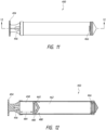
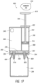
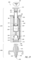
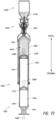
- Figures 11 and 12 illustrate side and cross-sectional views of a plunger 450 (e.g., a tube, actuator, shaft, etc.) that can be part of some or all of the syringe assemblies disclosed.
- the plunger 450 can include a finger grip 454 to enable a user to push the plunger 450 distally at least partially into a barrel (e.g., a housing, casing, enclosure, etc.) and pull the plunger 450 proximally at least partially out of the barrel.
- a barrel e.g., a housing, casing, enclosure, etc.
- the plunger 450 can include a vent 456 to enable ambient air to enter a proximal portion 458 of the plunger 450 to reduce a difference in pressure between the pressure in the proximal portion 458 and the pressure in a first reservoir 462 by causing a proximal plunger seal 460 to move distally or proximally inside of the plunger 450.
- a hole 466 can allow gas (or liquid) to flow from the first reservoir 462 into a passage and then into a container (not shown).
- Some embodiments include a plurality of holes 466, which can facilitate fluid flowing into and/or out of the first reservoir 462.
- Many different plungers are disclosed herein. Any plunger can be used with any syringe system disclosed herein.
- the proximal plunger seal 460 can have a contact region 480, which is the region of the proximal plunger seal 460 that can contact the inner diameter of the plunger 450 or another inner surface of the plunger 450 that forms the sealing surface along which the proximal plunger seal 460 slides in a distal or proximal direction.
- the length of the contact region 480 is at least about 25% of the inner diameter of the plunger; at least about 50% of the inner diameter of the plunger; at least about 25% of the inner diameter of the plunger and/or less than or equal to about 200% of the inner diameter of the plunger; at least about 40% of the inner diameter of the plunger and/or less than or equal to about 75% of the inner diameter of the plunger; or at least about 50% of the inner diameter of the plunger and/or less than or equal to about 100% of the inner diameter of the plunger.
- the length of the contact region 480 is at least about 0.2 centimeters and/or less than or equal to about 3 centimeters; at least about 0.5 centimeters and/or less than or equal to about 2 centimeters; or at least about 0.7 centimeters and/or less than or equal to about 1.5 centimeters.
- the proximal plunger seal 460 is lubricated to facilitate sliding within the plunger 450.
- the inner diameter of the plunger 450 can be lubricated. Petroleum-based lubricants and silicone lubricants are used in some embodiments. Some embodiments do not use lubricants.
- the plunger 450 are configured to stop the proximal plunger seal 460 from moving proximally beyond a certain position (e.g., the farthest proximal position).
- the proximal plunger seal 460 has a starting position or a shipping position that is not in the furthest proximal position.
- the distance between the furthest proximal position that the proximal plunger seal 460 can reach and the location of the proximal plunger seal 460 is called the gap distance 484.
- a gap distance can help accommodate pressure changes (e.g., increases) post-manufacturing.
- the first reservoir could have a pressure higher than ambient pressure at 2,000 meters if the proximal plunger seal 460 is not allowed to move sufficiently in the proximal direction.
- a sufficiently large gap distance 484 can accommodate decreases in ambient pressure by allowing the first reservoir 462 to increase in volume to reduce the difference in pressure between inside the first reservoir 462 and outside of the first reservoir 462.
- the gap distance 484 is at least about 0.5 centimeters and/or less than or equal to about 10 centimeters; at least about 1 centimeter and/or less than or equal to about 5 centimeters; or at least about 1.5 centimeters and/or less than or equal to about 4 centimeters.
- Some methods include shipping a plunger 450 to a customer when the gap distance has one of the dimensions or dimensional ranges stated above.
- some embodiments of the plunger 450 include a securing or locking feature 488. This can be used to hold the proximal plunger seal 460 in a location until a sufficiently large pressure differential overcomes the locking feature 488.
- the locking feature 488 can be a projection and/or a protrusion (e.g., a rounded bump) that protrudes radially inward from the inner diameter of the plunger 450.
- Figure 32 illustrates a perspective view of an adapter assembly 1450.
- the distal end 1454 of the adapter assembly 1450 is configured to couple to containers.
- the proximal end 1458 of the adapter assembly 1450 is configured to couple to the syringe assembly 1402 illustrated in Figure 29 .
- the piercing member can include at least a portion of the distal first passage 1246 and at least a portion of the distal second passage 1254.
- the skirt 1478 can include at least a portion of the distal first passage 1246 and at least a portion of the distal second passage 1254.
- the distal first passage 1246 and the distal second passage 1254 are indicated by dashed lines.
- the sliding member 1576 can reciprocate proximally and distally.
- the sliding member 1576 can slide up and down on the distal shaft 2832 of the barrel body 2816.
- the sliding member 1576 can include one or more axial protrusions 1566, such as flexible arms or rigid arms that extend distally.
- the axial protrusions 1566 can extend in a direction approximately parallel to the central axis of the syringe assembly 1402.
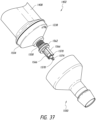
- the syringe assembly 1402 can include a fourth seal 1570, which can be a generally cylindrical seal with a lumen and/or a seal with a cylindrical portion and a central lumen.
- a passage shaft 1574 can contain a second passage (e.g., proximal second passage 1424 in Figure 31 ).
- the passage shaft 1574 can pass through the lumen of the fourth seal 1570, which can be made from rubber or any other suitable material. Any of the seals described herein can be made from rubber, such as medical-grade rubber, or any other suitable sealing material.
- the syringe assembly 1402 can include a fifth seal 1588, such as an O-ring (see Figure 38 ).
- the fifth seal 1588 can be retained in a groove, such as in the distal shaft 2832.
- the fifth seal 1588 can provide a generally liquid-tight and/or gas-tight seal between the sliding member 1576 and the distal shaft 2832.
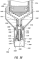
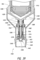
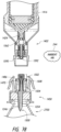
- Figures 38 and 39 illustrate cross-sectional views of a distal portion of the syringe assembly 1402.
- An adapter assembly e.g., No. 1450 in Figure 40
- the syringe assembly 1402 is shown in a configuration in which the syringe assembly 1402 is not coupled to an adapter assembly (e.g., No. 1450 in Figure 40 ).
- the syringe assembly 1402 is shown as coupled to the adapter assembly (e.g., No. 1450 in Figure 40 ), although for presentation purposes the adapter assembly is not shown in Figure 39 .
- the syringe assembly 1402 can be said to "closed” and in Figure 39 , the syringe assembly 1402 can be said to "open.”
- the adapter assembly has pushed the distal portion 1584 of the passage shaft 1574 in a proximal direction to open the proximal second passage 1424. Such movement can be against the compressive force of the spring 1558. As illustrated, the sliding member 1576 and the distal portion 1584 of the passage shaft 1574 have been pushed in a proximal direction (relative to the configuration shown in Figure 38 ) by the proximal shaft 1494 (not shown) of the adapter assembly 1450 (not shown).
- Increasing the effective volume of the second reservoir 1444 and/or the proximal second passage 1424 can decrease local pressure, and thus, can "vacuum” or “suck” fluid into the second reservoir 1444 and/or into the proximal second passage 1424 (e.g., during decoupling), which can reduce or minimize the amount of potentially harmful liquid (e.g., medical fluid, extracted medicinal fluid) that may drip and/or escape from the syringe assembly 1402 and/or the adapter assembly 1450 (shown in Figure 41 ).
- This safety feature can reduce medical professionals' exposure to the liquid.
- the maximum volume of the expansion chamber 1582 is at least about 150% of the minimum volume of the expansion chamber 1582 or is at least about 300% of the minimum volume of the expansion chamber 1582. In some embodiments, the maximum volume of the expansion chamber 1582 is at least about 200% of the minimum volume of the expansion chamber 1582 and/or less than or equal to about 10,000% of the minimum volume of the expansion chamber. In some embodiments, the maximum volume of the expansion chamber 1582 is at least about 400% of the minimum volume of the expansion chamber 1582 and/or less than or equal to about 2,000% of the minimum volume of the expansion chamber 1582.
- the expansion chamber 1582 increases an internal volume of the syringe assembly 1402 (e.g., the volume of the second reservoir 1444, the volume of the proximal second passage 1424) by at least about 0.2 milliliters and/or less than or equal to about 25 milliliters; at least about 0.7 milliliters and/or less than or equal to about 10 milliliters; at least about 1 milliliter and/or less than or equal to about 3 milliliters; or at least about 2 milliliters and/or less than or equal to about 10 milliliters.
- the third seal 1562 engages an inner surface 1580 of the syringe assembly 1402 (e.g., an inner surface of the distal cap 1550) to seal the proximal first passage 1416.
- fluid such as gas
- the third seal 1562, the inner surface 1580, and the spring 1558 can form a flow controller such as a valve (e.g., No. 228 in Figure 7 ) to close and/or seal a first passage. Pressing axially on the distal portion 1584 of the passage shaft 1574 can overcome the axial spring force of the spring 1558. Overcoming the spring force causes the valve to open to allow fluid, liquid, and/or gas flow.
- Figure 40 illustrates a cross-sectional view of a pressure-regulating syringe system comprising the syringe assembly 1402 from Figure 29 and the adapter assembly 1450 from Figure 32 .
- the system shown in Figure 40 can be the same or identical to any of the other pressure-regulating syringe systems described herein and can include any of the features of those other systems.
- the second seal 1486 is coupled between the spring 1504 and an axial sealing surface 1592.
- the second seal 1486 can provide generally gas-tight sealing and/or can fluidly seal the proximal second passage 1424 and the distal second passage 1254 (shown in Figure 28 ) to facilitate fluid flow between the proximal second passage 1424 and the distal second passage 1254.
- fluid can flow between the second passages 1424, 1254, and the second passages 1424, 1254 can be fluidly isolated from the first passages 1416, 1246.
- the syringe assembly 1402 can be rotated (e.g., at least about: 45 degrees, 110 degrees, 290 degrees, 500 degrees, 1,000 degrees, values between the aforementioned values, or any other number of degrees) without impeding the ability of the system to transmit fluid (e.g., gas, liquid) between the proximal second passage 1424 and the distal second passage 1254.
- fluid e.g., gas, liquid
- the ability of the syringe assembly 1402 to be rotated around its central axis relative to the adapter assembly 1450 can simplify coupling the syringe assembly 1402 to the adapter assembly 1450 and/or can facilitate embodiments that use threads to couple (e.g., tighten) the syringe assembly 1402 to the adapter assembly 1450.
- the syringe assembly 1402 cannot be rotated indefinitely relative to the adapter assembly 1450, but can be rotated until the syringe assembly 1402 is fully coupled to the adapter assembly 1450 (e.g., the threads are fully or substantially fully engaged).
- the syringe assembly 1402 can be rotated indefinitely relative to the adapter assembly 1450.
- the syringe assembly 1402 can include a penetrating member 1442.
- the penetrating member 1442 can pass into at least a portion of the adapter assembly 1450.
- the penetrating member 1442 does not pierce as it passes into the adapter assembly 1450.
- the penetrating member 1442 is dull (e.g., not sharp) such that it would not cut a person in normal use even if the penetrating member 1442 was exposed.
- the penetrating member 1442 is recessed within an outer covering 1440 (labeled in Figure 39 ) such that the penetrating member 1442 is inaccessible by a person or at least is generally inaccessible (during normal operating use).
- the outer covering 1440 can be a portion of the distal cap 1550, as shown in Figure 39 .
- the distal end of the penetrating member is recessed at least about 0.2 centimeters and/or less than or equal to about 11 centimeters from the distal end of the outer covering 1440. In some embodiments, the distal end of the penetrating member is recessed at least about 0.5 centimeters and/or less than or equal to about 6 centimeters from the distal end of the outer covering 1440. In some embodiments, the distal end of the penetrating member is recessed at least about 0.8 centimeters and/or less than or equal to about 3 centimeters from the distal end of the outer covering 1440.
- a component e.g., the penetrating member 1442 is configured to penetrate into a portion of the adapter assembly 1450 and/or into a portion of a container.
- the component e.g., penetrating member 1442
- the component can remain recessed, covered, or otherwise shielded by the syringe assembly 1402 throughout the use of the system 1400 and/or when the syringe assembly 1402 is in a pre-use state (e.g., upon removal from packaging), in a post-use state (e.g., having been coupled and decoupled from the adapter 1450), initially disposed, thrown away, and/or discarded.
- the proximal first passage 1416 can be a regulating channel to convey or otherwise transmit fluid that regulates pressure inside of a container.
- the distal first passage 1246 can be a regulating channel to convey or otherwise transmit fluid that regulates pressure inside of a container.
- the proximal second passage 1424 and the distal second passage 1254 can be extraction channels configured to remove fluid from a container and/or deliver fluid to a container.
- the syringe assembly 1402 can include a first biasing member (e.g., a spring 1558) and/or a regulating channel seal (e.g., third seal 1562).
- the first spring 1558 can be configured to apply an axial force to press the regulating channel seal against a sealing surface (e.g., inner surface 1580) to seal the regulating channel.
- the adapter assembly 1450 can include a distally protruding piercing member (e.g., the distal portion of the piercing member 1500 in Figure 36A ).
- the distally protruding piercing member can be configured to enable fluid communication with an internal portion of a container (e.g., a vial).
- the adapter assembly 1450 can include a proximally protruding member (e.g., the proximal end 1510 in Figure 36A ), which can be configured to compress the first spring (e.g., spring 1558 in Figure 41 ) to unseal the regulating channel (e.g., the proximal first passage 1416 in Figure 41 ).
- the adapter assembly 1450 can include a passage (e.g., the distal first passage 1246 and/or the distal second passage 1254 in Figure 41 ).
- the passage can be capable of fluid communication with an internal portion of a container, such as a vial.
- the adapter assembly 1450 can include a second spring (e.g., spring 1504 in Figure 41 ) axially coupled to an adapter seal (e.g., the second seal 1486 in Figure 41 ).
- the second spring can be configured to move the adapter seal to seal the passage of the adapter.
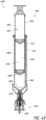
- Figures 42-45 illustrate various configurations and views of the syringe assembly 1402 and the adapter assembly 1450.
- Figure 42 illustrates the syringe assembly 1402 of Figure 41 mechanically and fluidly coupled to the adapter assembly 1450 of Figure 41 .
- Figure 43 illustrates the syringe assembly 1402 of Figure 41 mechanically and fluidly uncoupled from the adapter assembly 1450 of Figure 41 .
- Figure 44 illustrates a close-up view of the syringe assembly 1402 mechanically and fluidly coupled to the adapter assembly 1450.
- Figure 45 illustrates a close-up view of the syringe assembly 1402 mechanically and fluidly uncoupled from the adapter assembly 1450. Not all of the features, components, and assemblies are labeled in Figures 42-45 to increase the clarity of the syringe assembly 1402 and adapter assembly 1450.
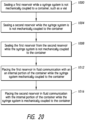
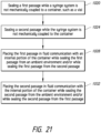
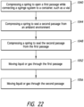
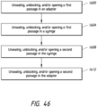
- Figure 46 illustrates a method of fluidly coupling a syringe to an adapter, according to several embodiments. This method can be used with any of the syringe systems and adapters described herein.
- Block 1600 can include unsealing, unblocking, and/or opening a first passage in an adapter.
- the first passage can be configured to fluidly communicate gas between a first reservoir and a container.
- the first passage can be a gas passage.
- the first passage in the adapter can be the distal first passage 1246, which can be unsealed, unblocked, and/or opened by moving the radial protrusion 1508 distally such that the radial protrusion 1508 of the second seal 1486 no longer contacts the inner tapered region 1518 of the adapter assembly 1450.
- Block 1604 of Figure 46 can include unsealing, unblocking, and/or opening a first passage in a syringe.
- the first passage in the syringe can be configured to fluidly communicate with the first passage in the adapter to form a first passage (e.g., 220 in Figure 7 ) between a first reservoir and a container.
- the first passage in the syringe can be the proximal first passage 1416, which can be sealed, blocked, and/or closed by moving the third seal 1562 in a distal direction such that the third seal 1562 seals against the inner surface 1580 (as shown in Figure 38 ).
- the proximal first passage 1416 can be unsealed, unblocked, and/or opened when the syringe assembly 1402 is coupled to an adapter such that the adapter presses the distal portion 1584 of the passage shaft 1574 in a proximal direction, which moves the third seal 1562 from a sealing, blocking, and/or closing position to an unsealing, unblocking, and/or opening position.
- Block 1608 of Figure 46 can include unsealing, unblocking, and/or opening a second passage in the syringe.
- the second passage can be configured to fluidly communicate a liquid between a second reservoir and the container.
- the second passage can be a liquid passage and/or can be configured to fluidly communicate medicine from a container, such as a vial.
- the second passage in the syringe can be the proximal second passage 1424.
- Figure 38 illustrates the proximal second passage 1424 in a sealed, blocked, and/or closed position.
- Figure 39 illustrates the proximal second passage 1424 in an unsealed, unblocked, and/or open position.
- the distal portion 1584 of the passage shaft 1574 can include a tapered portion that seals, blocks, and/or closes against a tapered portion 1548 of the distal cap 1550 in a seal zone 1590.
- the proximal second passage 1424 includes a "self-engaging" sealing system 1568.
- greater pressure inside the proximal second passage 1424 increases the sealing force of the sealing system, flow controller, and/or valve that controls flow through the proximal second passage 1424.
- the self-engaging sealing system 1568 can include a surface against which pressure drives two sealing surfaces together to tighten a seal. In several embodiments, the surface can be perpendicular to the direction of travel that causes the sealing surfaces to tighten together. In some embodiments, greater pressure against an actuation surface 1572 pushes a distal portion 1584 of the passage shaft 1574 towards a tapered portion 1584 to increase the seal strength.
- Block 1612 of Figure 46 can include unsealing, unblocking, and/or opening a second passage in the adapter.
- the second passage in the adapter can be configured to fluidly communicate with the second passage in the syringe to form a second passage (e.g., 224 in Figure 7 ) between a second reservoir and a container.
- a second passage e.g., 224 in Figure 7
- the second passage in the adapter can be the distal second passage 1254.
- Figure 36A illustrates the distal second passage 1254 in an unsealed, unblocked, and/or open position because the second seal 1486 is in a distal location (rather than in a proximal sealing location 1502) so the second seal 1486 does not cover, seal, occlude, and/or block the radial hole 1528.
- fluid such as a medical liquid
- fluid can flow through the distal second passage 1254, through the radial hole 1528, and into the proximal second passage 1424 (shown in Figure 39 ).
- Blocks 1600, 1604, 1608, and 1612 can be performed in any order. Some embodiments perform these Blocks in specific orders. In some embodiments, Block 1600 is performed first, Block 1604 is performed second, Block 1608 is performed third, and Block 1612 is performed fourth.
- Several embodiments include opening a first passage in an adapter; then opening a first passage in a syringe; then opening a second passage in the syringe; and then opening a second passage in the adapter.
- Some embodiments include unsealing, unblocking, and/or opening a first passage before unsealing, unblocking, and/or opening a second passage, wherein the first passage is configured to communicate gas and the second passage is configured to communicate liquid.
- Several embodiments include fluidly coupling a container, such as a vial, to a gas reservoir before fluidly coupling the container to a reservoir configured to hold liquid, such as a medicinal fluid.
- Several embodiments include fluidly coupling a container, such as a vial, to a pressure equalization reservoir before fluidly coupling the container to a reservoir configured to hold medicinal fluid.
- Some embodiments include fluidly sealing an internal portion of an adapter to an internal portion of a syringe prior to performing at least one of or all of Blocks 1600, 1604, 1608, and 1612.
- the first seal 1470 can fluidly seal an internal portion of the adapter assembly 1450 to an internal portion of the syringe assembly 1402.
- the syringe system can create an internally isolated area prior to opening the proximal first passage 1416, the proximal second passage 1424, the distal first passage 1246, and/or the distal second passage 1254 (as shown in Figures 36A and 39 ).
- Figure 47 illustrates a method of fluidly uncoupling a syringe from an adapter, according to several embodiments. This method can be used with any of the syringe systems and adapters described herein.
- Block 1630 can include sealing, blocking, and/or closing a second passage in an adapter.
- Block 1634 can include sealing, blocking, and/or closing a second passage in a syringe.
- Block 1638 can include sealing, blocking, and/or closing a first passage in the syringe.
- Block 1642 can include sealing, blocking, and/or closing a first passage in the adapter.
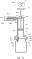
- the valve 1716 can include a cap configured to enable a user to "flip" the cap to an open position using a thumb.
- the valve 1716 can include a pinch valve, a duckbill valve, a check valve, a clack valve, a one-way valve, a ball valve, a diaphragm check valve, a swing check valve, a tilting disc check valve, a stop check valve, a lift check valve, an in-line check valve, and/or a two-way valve.
- Certain other embodiments do not include the outside fluid access port.
- numerous other embodiments disclosed in this specification do not include the outside fluid access port.
- Several embodiments that do not include the outside fluid access port are configured such that no external (e.g., ambient) fluid is used as regulating fluid.
- no external (e.g., ambient) fluid is used as regulating fluid.
- a flexible container e.g., an IV bag
- no outside fluid is used as regulating fluid.
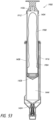
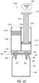
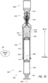
- Figure 49 illustrates a perspective, cross-sectional view along the line 49-49 from Figure 48 when the syringe assembly 1704 is coupled to the adapter assembly 1708.
- the syringe assembly 1704 can include a first reservoir 1760 separated from a second reservoir 1764 by a distal plunger seal 1768.
- the distal plunger seal 1768 can be coupled to a distal end of the plunger 1740.
- a proximal end of the first reservoir 1760 can be sealed by a proximal seal 1772.
- the plunger 1740 can slidably pass through a central lumen of the proximal seal 1772.
- a first passage 1776 can be configured to place the first reservoir 1760 in fluid communication with a container, such as a container configured to hold medicine.
- a second passage 1780 can be configured to place the second reservoir 1764 in fluid communication with the container.
- the barrel 1724 (which can be a housing) can include an inner channel 1778 with a diameter.
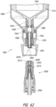
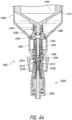
- Figure 50 illustrates a perspective, cross-sectional view of the adapter assembly 1708 of Figure 48 with the plunger 1740 and distal plunger seal 1768 moved to a distal position.
- the adapter assembly 1708 is in close proximity to the syringe assembly 1704, but not coupled to the syringe assembly 1704.
- the syringe assembly 1704 can include a proximal first passage 1800 configured to be fluidly coupled with a distal first passage 1856 of the adapter assembly 1708.
- a distal opening 1804 can allow fluid to flow from a portion of the proximal first passage 1800 into an open area 1888 inside a distal portion of the syringe assembly 1704.
- the open area 1888 can be sealed, blocked, and/or closed by a third seal 1870, which can be an O-ring.
- the syringe assembly 1704 is disconnected from the adapter assembly 1708 so the third seal 1870 seals against an inner surface 1828 to seal, block, and/or close the proximal first passage 1800 to prevent air located inside of a first reservoir from leaking outside of the syringe assembly 1704.
- a fourth seal 1844 can allow a passage shaft 1808 to slide within a lumen of the fourth seal 1844 such that the passage shaft 1808 can move distally and/or proximally.
- a biasing member such as a spring 1824, pushes the passage shaft 1808 in a distal direction.
- the adapter assembly 1708 can overcome the spring force of the spring 1824 when the syringe assembly 1704 is coupled to the adapter assembly 1708 to force the passage shaft 1808 to a proximal position, which disengages the third seal 1870 to open, unseal, and/or unblock the proximal first passage 1800 and/or disengages a seal zone 1854 (indicated by a dashed rectangle) between the passage shaft 1808 and a distal portion of the syringe assembly 1704 to open, unseal, and/or unblock the proximal second passage 1832.
- a protrusion 1816 that protrudes radially inward from a flexible arm 1820 is located inside of a groove 1812 to help secure the syringe assembly 1704 to the adapter assembly 1708.
- Some embodiments include threads to mechanically couple the syringe assembly 1704 to the adapter assembly 1708 (see, e.g., Figures 25 and 26 ).
- the adapter assembly 1708 can include a distal second passage 1848 and a distal first passage 1856.
- a portion of the distal second passage 1848 and a portion of the distal first passage 1856 can be located inside of the piercing member 1852.
- the distal second passage 1848 can be configured to fluidly couple with the proximal second passage 1832 when the syringe assembly 1704 is mechanically and/or fluidly coupled to the adapter assembly 1708.
- the distal first passage 1856 can be configured to fluidly couple with the proximal first passage 1800 when the syringe assembly 1704 is mechanically and/or fluidly coupled to the adapter assembly 1708.
- the first passage can be fluidly isolated and/or sealed from the second passage when the syringe assembly 1704 is not coupled to the adapter assembly 1708 and/or when the syringe assembly 1704 is coupled to the adapter assembly 1708.
- a second seal 1874 can be configured to seal against an inner tapered region 1890.
- a biasing member such as a spring 1836, can push the second seal 1874 in a proximal direction. Coupling the syringe assembly 1704 to the adapter assembly 1708 can compact the spring 1836 to unseal, unblock, and/or open the distal first passage 1856 and the distal second passage 1848.
- the first seal 1878 is in an unsealed, unblocked, and/or open position.
- the second seal 1874 seals, blocks, and/or closes the distal second passage 1848 and/or the distal first passage 1856.
- Figure 51 illustrates a perspective, cross-sectional view of the adapter assembly 1708 along the line 49-49 from Figure 48 , when the adapter assembly 1708 is coupled to the syringe assembly 1704.
- the seal zone 1854 is open, unblocked, and/or unsealed when the syringe assembly 1704 is coupled to the adapter assembly 1708.
- the first seal 1878 is in a sealed, blocked, and/or closed position in Figure 51 .
- the second seal 1874 can seal the transition between the proximal second passage 1832 and the distal second passage 1848. In some embodiments, the second seal can also permit the proximal second passage 1832 and the distal second passage 1848 to be in fluid communication. In some embodiments, the second seal 1874 can permit the proximal first passage 1800 and the distal first passage 1856 to be in fluid communication. In Figure 51 , the second seal 1874 seals and/or blocks fluid communication between the first passage and the second passage.
- Figures 52 and 53 illustrate cross-sectional, side views of another embodiment of a syringe assembly 1900 with a bag 1908 located inside of a housing.
- the system shown in Figures 52 and 53 can be the same or identical to any of the other pressure-regulating syringe systems described herein and can include any of the features of those other systems.
- the syringe assembly 1900 can include a bag 1908, which is illustrated in a collapsed and folded configuration.
- An internal portion of the bag 1908 includes a first reservoir 1904 configured to be fluidly coupled with an internal portion of a container via the proximal first passage 1416.
- the bag 1908 can be located inside of the syringe assembly 1900 and inside of a plunger 1404.
- the bag 1908 can fluidly separate the first reservoir 1904 from a third reservoir 1912 (e.g., ambient portion).
- the third reservoir 1912 can be placed in fluid communication with ambient air via a vent 1436, hole, valve, and/or filter.
- the vent 1436 is located in a proximal portion of the plunger 1404.
- Figure 53 illustrates the bag 1908 in an expanded and unfolded configuration.
- the bag 1908 does not stretch when it expands, but the internal volume of the bag 1908 increases as the bag expands (e.g., unfolds).
- the internal volume of the bag 1908 is larger in Figure 53 than in Figure 52 .
- the volume of the third reservoir 1912 is smaller in Figure 53 than in Figure 52 .
- the surface area of the bag 1908 in Figure 53 is equal (or at least approximately equal) to the surface area of the bag 1908 in Figure 52 .
- the surface area of an expanded bag is within +/- 5%, +/-10%, or +/-20% of the surface area of a collapsed bag such that the bag is configured not to substantially stretch during expansion and/or inflation (during normal operating conditions).
- the bag's material does not cause the bag to have a restoring force.
- the bag 1908 expands (e.g., increases in internal volume) the bag 1908 stretches and/or imparts a restoring force on the fluid in the bag 1908.
- Figure 54 illustrates a cross-sectional view of an embodiment of a pressure regulating syringe system 2000 with a supplemental reservoir 2004, which can be configured to provide additional volume to a first reservoir 712.
- the system 2000 can be the same or identical to any of the other pressure-regulating syringe systems described herein and can include any of the features of those other systems.
- the supplemental reservoir 2004 can have rigid walls and can be located outside of the barrel 390 and/or plunger 720.
- the supplemental reservoir 2004 can have an internal volume that is at least 50% of the volume of the first reservoir 712 and/or less than 300% of the volume of the first reservoir 712 (as measured at the largest potential volume of the first reservoir 712 under normal operating conditions).
- the supplemental reservoir 2004 can have an internal volume that is at least 110% of the volume of the first reservoir 712 and/or less than 500% of the volume of the first reservoir 712.
- the supplemental reservoir 2004 can have an internal volume that is at least 200% of the volume of the first reservoir 712 and/or less than 900% of the volume of the first reservoir 712.
- the sum of the maximum volumes of the supplement reservoir and the first reservoir can be larger than the maximum volume of the second reservoir.
- a valve 704 can control (e.g., block) fluid communication between the first reservoir 712 and the supplemental reservoir 2004.
- the supplemental reservoir 2004 can be used when a medical professional determines that additional gas and/or volume is necessary, desirable, and/or beneficial to regulate pressure inside the container 304.
- the supplemental reservoir 2004 can couple to the pressure regulating syringe system 2000, to the barrel 390, and/or to the plunger 720 via threads.
- the supplemental reservoir 2004 can be in fluid communication with the first reservoir 712. Some embodiments include moving fluid from the second reservoir 312 to the container 304 and/or moving fluid from the container 304 to the second reservoir 312 before placing the supplemental reservoir 2004 in fluid communication with the first reservoir 712 and/or container 304.
- Figure 55 illustrates a cross-sectional view of an embodiment in which a supplemental reservoir 2020 includes a bag 2008, which can be located inside of walls 2012.
- the system illustrated in Figure 55 can be the same or identical to any of the other pressure-regulating syringe systems described herein and can include any of the features of those other systems.
- the walls 2012 can be rigid.
- a vent 2016 can allow ambient air to enter the supplemental reservoir 2020.
- the bag 2008 can fluidly seal the first reservoir 712 from the ambient air such that ambient air does not contact the interior surface of the bag 2008. In various embodiments, ambient air can contact an exterior surface of the bag 2008.
- Figure 56 illustrates a cross-sectional view of an embodiment in which a supplemental reservoir 2024 includes a bag 2008 coupled to the barrel 390.
- the bag 2008 is not surrounded and/or encased by rigid walls.
- Figures 57-59 illustrate seals with a rigid inner body and a compliant sealing member configured to fluidly seal against an inner surface of a plunger.
- the compliant sealing member can be positioned around at least a portion of the rigid inner body.
- the seals of Figures 57-59 can be used with any of the systems or components described herein.
- the seals of Figures 57-59 can be used in place of other proximal plunger seals described and/or illustrated herein.
- Figure 57 illustrates a side view of a proximal plunger seal 2040 with seals, such as gaskets, rubber protrusions, or O-rings 2044, placed partially within grooves around the outer diameter of the proximal plunger seal 2040.
- the O-rings 2044 can be made from a compliant, rubber material. Some embodiments include O-rings 2044 made of medical-grade silicone or neoprene. Several embodiments include at least two O-rings coupled to a rigid carrier 2048, which can be made of molded plastic and/or machined. In some embodiments, the carrier 2048 is molded and then machined (e.g., deflashed, on a lathe, on a grinder) to remove parting lines to facilitate the O-rings 2044 sealing against the outer surface of the carrier 2048.
- seals such as gaskets, rubber protrusions, or O-rings 2044
- a distal portion can include a seal (e.g., an O-ring 2044) and a proximal portion can include a seal (e.g., an O-ring 2044). Some embodiments include three or more seals.
- One or both ends of the carrier 2048 can include a rounded or chamfered edge 2052 to avoid catching (e.g., snagging) an interior surface of a plunger (e.g., 1404 in Figure 30 ).
- the carrier can be configured to prevent the proximal plunger seal 2040 from canting.
- a first seal (e.g., O-ring 2044) is spaced at least 0.5 cm, 0.75 cm, or 1 cm from a second seal (e.g., O-ring 2044).
- the outer diameter of the carrier 2048 is at least 80% and/or less than 99% of the inner diameter of the plunger in which the carrier 2048 is located. In some embodiments, the outer diameter of the carrier 2048 is at least 90% and/or less than 98% of the inner diameter of the plunger in which the carrier 2048 is located.
- Figure 58 illustrates a side view of a proximal plunger seal 2060 with wiper seals 2064 placed partially within grooves around the outer diameter of the proximal plunger seal 2060.
- the wiper seals 2064 can be made from medical-grade silicone or neoprene.
- the wiper portion of the wiper seals 2064 can extend radially outward from a carrier 2068.
- a wiper seal 2064 can be placed on a distal portion of the carrier 2068 and a wiper seal 2064 can be placed on a proximal portion of the carrier 2068.
- a first wiper seal 2064 is spaced at least 0.5 cm, 0.75 cm, or 1 cm from a second wiper seal 2064.
- the outer diameter of the carrier 2068 is at least 80% and/or less than 99% of the inner diameter of the plunger in which the carrier 2068 is located. In some embodiments, the outer diameter of the carrier 2068 is at least 90% and/or less than 98% of the inner diameter of the plunger in which the carrier 2068 is located.
- Figure 59 illustrates a side view of a proximal plunger seal 2080 with a wiper seal 2084 placed partially within a groove around the outer diameter of the proximal plunger seal 2080.
- the groove can be part of the carrier 2088, which can be configured to secure and/or hold a seal, such as a wiper seal 2084.
- the carrier 2088 can include a first diameter and a second diameter.
- a seal e.g., wiper seal 2084, an O-ring
- a seal can protrude radially outward from a portion of the carrier 2088 that includes the first diameter 2092.
- the second diameter 2096 can be larger than the first diameter 2092 and can be spaced apart from a portion of the proximal plunger seal 2080 that includes a seal (e.g., the wiper seal 2084).
- the second diameter 2096 can be a support surface configured to limit the degree to which the proximal plunger seal 2080 is able to cant within a plunger.
- the second diameter 2096 can be smaller than the outer diameter of the seal (e.g., wiper seal 2084).
- the second diameter 2096 can be made from a rigid material, such that it can form a rigid support surface configured to limit the degree to which the proximal plunger seal 2080 is able to cant within a plunger.
- the outer diameter of the seal is larger than the second diameter, which is larger than the first diameter.
- Figure 60 illustrates a cross-sectional, side view of a pressure regulating syringe system 2100.
- the system 2100 can be the same or identical to any of the other pressure-regulating syringe systems described herein and can include any of the features of those other systems.
- the pressure regulating syringe system 2100 includes a seal 2104, which can be a wiper seal with multiple wipers.
- the seal 2104 can form a proximal boundary of a first reservoir 2108 configured to communicate fluid, such as a gas, via a first passage 816 to and/or from an internal portion 810 of a container 304.
- the seal 2104 can be slidably coupled within the pressure regulating syringe system 2100 such that the seal 2104 can slide within a portion of the pressure regulating syringe system 2100 to change the volume of the first reservoir 2108.
- the pressure regulating syringe system 2100 can include a second reservoir 2116 configured to communicate fluid, such as a liquid, via a second passage 826 to and/or from an internal portion 810 of a container 304.
- a second reservoir 2116 configured to communicate fluid, such as a liquid, via a second passage 826 to and/or from an internal portion 810 of a container 304.
- the longitudinal axes of the first and second reservoirs can be offset and non-colinear in some embodiments.
- the longitudinal axes of the first and second reservoirs can be generally parallel.
- a plunger seal 2112 can form a proximal boundary of the second reservoir 2116.
- Stops 2120, 2124 can limit the travel of the seal 2104 and the plunger 720 to prevent and/or reduce the likelihood of the seal 2104 and the plunger 720 to inadvertently decouple from the pressure regulating syringe system 2100.
- the stops 2120, 2124 can be protrusions that protrude radially inward to interfere with the seal 2104 and/or a portion of the plunger 720 when the seal 2014 and/or the plunger 720 reaches a proximal travel termination point.
- the stops 2120, 2124 can be located proximally relative to the seal 2104 and/or the plunger seal 2112.
- Figure 61 illustrates the pressure regulating syringe system 2100 after the seal 2104 has moved distally and the plunger 720 has moved proximally.
- the seal 2104 and the plunger 720 e.g., including the plunger seal 2112
- the seal 2104 and the plunger 720 are configured to slide distally and proximally within the pressure regulating syringe system 2100.
- Syringe assemblies can be coupled to vial adapters and/or can be coupled to other fluid transfer connectors.
- medical professionals can connect syringe assemblies to containers that are not vials.
- syringe assemblies are used to remove a pharmaceutical substance from a container such as a vial and then are used to inject the pharmaceutical substance into peripheral, arterial, and/or central venous catheters.
- Syringe assemblies can be used to deliver pharmaceutical substances to an intravenous therapy ("IV") bag or IV line.
- IV intravenous therapy
- syringe assemblies are mechanically and fluidly coupled to a Clave ® needle-free connector commercially available from ICU Medical, Inc.
- Figure 62 illustrates a cross-sectional view of the syringe assembly 1402 from Figure 38 and a connector 2200.
- the syringe assembly 1402 is not coupled to the connector 2200.
- the connector 2200 can be configured to mechanically and fluidly couple with a tube, cannula, container, and/or bag.
- the connector 2200 can include a distal second passage 2204 configured to and/or capable of being placed in fluid communication with the proximal second passage 1424 of the syringe assembly 1402.
- a proximal portion of the distal second passage 2204 can be sealed by a second seal 2208, which can be configured to cover a connector proximal aperture 2212 from the distal second passage 2004 and can be configured to provide substantially fluid-tight sealing of the connector proximal aperture 2212.
- the connector proximal aperture 2212 can be oriented radially outward from the central axis of the distal second passage 2204.
- the connector proximal aperture 2212 can be an aperture, a hole, and/or an exit of a passage (e.g., the distal second passage 2204).
- the second seal 2208 can include a sealing surface 2216 facing proximally. In some embodiments, during coupling of the syringe assembly 1402 and the connector 2200, the sealing surface 2216 is oriented towards a distal end 2220 of the syringe assembly 1402 and/or of the proximal second passage 1424. The sealing surface 2216 can also be oriented in a proximal direction relative to the connector 2200. In some embodiments, the second seal 2208 is a boot seal. The second seal 2208 can be made from rubber or medical-grade silicone. In various implementations, the second seal 2208 can resiliently and axially collapse (e.g., in a distal direction).
- the second seal 2208 is shown in a fully extended position.
- the syringe assembly 1402 is configured to compress the second seal 2208 in a distal direction to expose the connector proximal aperture 2212, to open the distal second passage 2204, and/or to place the distal second passage 2204 in fluid communication with the proximal second passage 1424.
- Figure 63 illustrates the connector 2200 during a stage of initial contact with the syringe assembly 1402.
- the sealing surface 2216 seals against at least a portion of the distal end 2220 of the syringe assembly 1402.
- the seal zone 1590 is still in a closed, sealed configuration in Figure 63 .
- the syringe assembly 1402 can include threads 1556.
- the threads 1556 can couple with threads 1586 of the connector 2200 so as to provide threaded engagement.
- the threads 1556, 1586 can transmit rotational movement into axial movement, such as distal movement or proximal movement.
- Figure 64 illustrates the connector 2200 partially coupled to the syringe assembly 1402.
- the connector 2200 and the syringe assembly 1402 are coupled.
- the connector 2200 and the syringe assembly 1402 can include corresponding threads, which can facilitate mechanical coupling.
- a proximal end 2224 of a pushing member such as a shaft or protrusion
- engages e.g., presses against
- the distal portion 1584 engages (e.g., presses against) the distal portion 1584. This can result in a proximally directed force, which can compress the spring 1558. This movement can open the seal zone 1590 (as shown in Figure 64 ).
- the seal zone 1590 can be in an open position and the distal second passage 2204 can be in fluid communication with the proximal second passage 1424, the third seal 1562 can still be in a closed position (as illustrated in Figure 64 ).
- the closed position of the third seal 1562 can block and/or inhibit fluid communication between the proximal first passage 1416 and the connector 2200.
- Figure 65 illustrates the connector 2200 coupled to the syringe assembly 1402.
- the proximal end 2224 continues to engage (e.g., push) the distal portion 1584, (which compresses the spring 1558) the second seal 2208 is compressed, which opens the connector proximal aperture 2212 by moving the second seal 2208 to a position in which the second seal 2208 is no longer sealing (e.g., covering) the connector proximal aperture 2212. Opening the connector proximal aperture 2212 places the distal second passage 2204 in fluid communication with the proximal second passage 1424 and/or the second reservoir 1444.
- fluid can flow between the second reservoir 1444 and the connector 2200 (e.g., an internal portion of the connector such as the distal second passage 2204).
- the sealing surface 2216 is configured to prevent fluid flowing between the proximal second passage 1424 and the distal second passage 2204 from leaking out.
- the aforementioned proximal movement of the sliding member 1576 and/or the compression of the spring 1558 moves the third seal 1562 proximally. This proximal movement can result in the third seal 1562 no longer contacting (or otherwise sealing with) the inner surface 1580. After the third seal 1562 no longer contacts the inner surface 1580, the third seal 1562 no longer seals the proximal first passage 1416 (e.g., is in an open position).
- the proximal first passage 1416 is open.
- the seal 1562 is spaced apart from the inner surface 1580, thereby allowing fluid to flow between seal 1562 and the inner surface 1580. This can open access to the proximal first passage 1416 and thus allow fluid to flow to and/or from that passage 1416.
- coupling the syringe assembly 1402 to a connector 2200 does not unseal the proximal first passage 1416, but connecting the syringe assembly 1402 to a vial adapter unseals the proximal first passage 1416. This can permit the syringe assembly 1402 to fluidly communicate gas into and out of a container such as a vial.
- the connector 2200 does not have a distal first passage (e.g., 1246 in Figure 41 ) configured to transmit fluid from a container to and/or from the syringe assembly 1402, coupling the connector 2200 to the syringe assembly 1402 will not unseal and/or open the proximal first passage.
- Coupling the connector 2200 to the syringe assembly 1402 can create a seal zone 2230 that seals and/or blocks the proximal first passage 1416 such that fluid (e.g., gas) from the first reservoir 1420 (shown in Figure 40 ) does not escape from the syringe assembly 1402 and/or escape into the ambient air 244, which is located outside of the syringe assembly 1402 and outside of the connector 2200.
- the seal zone 2230 can be formed by any suitable seal, including mating threads of the connector 2200 and the syringe assembly 1402. In the embodiment illustrated in Figure 65 , boxes formed by dashed lines indicate the area in which there are mating threads that inhibit or prevent fluid from exiting the proximal first passage 1416.
- Some embodiments include seal zones 2230 that block fluid transfer via seals (e.g., O-rings, gaskets or otherwise) in addition to, or instead of, mating threads.
- Some mating thread embodiments use plastics that provide enough compliance to form a gas seal and/or a generally gas-tight seal between the mating threads.
- the proximal first passage 1416 in Figure 65 includes a relatively large open area 2234 that can be sealed by the third seal 1562 and/or by the seal zone 2230.
- the connector 2200 does not include a distal first passage 1246 (shown in Figure 41 ) configured to transmit fluid (e.g., gas) from a first reservoir 1420 (shown in Figure 40 ) through the connector 2200 (e.g., to a container that can be located distally relative to the connector 2200).
- Some connectors 2200 include a passage to transmit fluid (e.g., a liquid) from a second reservoir but do not include a passage to transmit fluid (e.g., a gas) from a first reservoir.
- the syringe assembly 1402 can be configured such that the volume of the second reservoir can change without requiring the volume of the first reservoir to change. As described above, this can be called volumetric independence. Volumetric independence of the first reservoir from the second reservoir can reduce or prevent substantial pressure deviations from atmospheric pressure.
- the first reservoir is not volumetrically independent from the second reservoir and the proximal first passage 1416 is sealed (e.g., when the syringe assembly 1402 is coupled to the connector 2200)
- transmitting fluid from the second reservoir 1444 through the connector 2200 could increase the volume of the first reservoir without permitting the proximal first passage 1416 to transmit fluid into the first reservoir to regulate the pressure inside of the first reservoir.
- the pressure inside of the first reservoir could drop below atmospheric pressure (e.g., create a "vacuum").
- first reservoir is not volumetrically independent from the second reservoir and the proximal first passage 1416 is sealed (e.g., when the syringe assembly 1402 is coupled to the connector 2200) then transmitting fluid through the connector 2200 to the second reservoir 1444 could decrease the volume of the first reservoir without enabling the proximal first passage 1416 to transmit fluid out of the first reservoir to regulate the pressure inside of the first reservoir.
- the pressure inside of the first reservoir could rise above atmospheric pressure (e.g., create an "over pressure").
- the first reservoir 1420 and the second reservoir 1444 are volumetrically independent for at least one of several reasons.
- the first reservoir 1420 and the second reservoir 1444 are located in separate housings (e.g., separate cylinders). Moving the plunger distally or proximally can change the volume of the second reservoir 1444, but does not necessarily change the volume of the first reservoir 1420.
- the volume of the first reservoir 1420 can change when a pressure gradient causes the proximal plunger seal 1412 to move (e.g., slide) within the plunger 1404.
- the volume of the first reservoir 1420 changes in response to pressure gradients rather than in response to changing the volume of the second reservoir 1444.
- Fluidly coupling the syringe assembly 1402 to an adapter assembly 1450 and to a container can create a closed volume system.
- a closed volume system the system is sealed from ambient air such that the volume of the system is generally constant during normal operation and/or does not change (at least until the seals start leaking).
- the container has a fixed volume (e.g., due to rigid walls) then reducing the volume of the second reservoir 1444 will typically cause the volume of the first reservoir 1420 to increase because transmitting fluid from the second reservoir 1444 to the container can displace fluid inside the container and the displaced fluid can be transmitted into the first reservoir 1420.
- the container has a fixed volume (e.g., due to rigid walls) then increasing the volume of the second reservoir 1444 will typically cause the volume of the first reservoir 1420 to decrease because transmitting fluid from the container to the second reservoir 1444 can reduce the pressure inside the container, which can cause fluid inside the first reservoir 1420 to flow into the container to regulate pressure.
- the container has a variable volume (e.g., due to flexible and/or compliant walls) then reducing the volume of the second reservoir 1444 will not typically cause the volume of the first reservoir 1420 to increase. This is because reducing the volume of the second reservoir 1444 does not necessarily increase the pressure inside of the first reservoir 1420.
- the pressure inside the first reservoir 1420 may remain generally constant (e.g., not increase)-aside from a restoring force provided by the container itself, such as the compressive restoring force of an inflated latex balloon. This is because transmitting fluid from the second reservoir 1444 to the variable volume container typically results in the volume of the container increasing, rather the pressure in the container increasing (which would tend to drive fluid from the container to the first reservoir 1420).
- the proximal plunger seal 1412 does not need to move to regulate pressure. Accordingly, the plunger seal 1412 can remain substantially stationary (e.g., relative to the plunger body).
- a container with a fixed volume is configured to change in volume by 0% to 15% under normal operating conditions.
- a glass or plastic vial does not change substantially in volume.
- a container with a variable volume is configured to change in volume by at least 50% under normal operating conditions.
- an IV bag can start with a volume of approximately 10 milliliters but can expand to a volume of approximately 100 milliliters. Other IV bags have different typical expansion ranges.
- Figure 66 illustrates a side view of a syringe assembly 1402 coupled to an IV bag 2250.
- a connector 2200 can fluidly and mechanically couple the syringe assembly 1402 to the IV bag 2250.
- the syringe assembly 1402 can transmit fluid to and/or from the IV bag 2250.
- the IV bag 2250 is a compliant container. The compliance of the IV bag 2250 can enable the internal pressure of at least a portion of the IV bag 2250 to be approximately equal to atmospheric pressure.
- the syringe assembly 1402 can be configured to deliver a fluid (e.g., a liquid) from the second reservoir to an internal portion of the IV bag without reducing the pressure inside the first reservoir below atmospheric pressure, more than 5% below atmospheric pressure, more than 10% below atmospheric pressure, more than 20% below atmospheric pressure, or more than 35% below atmospheric pressure.
- a fluid e.g., a liquid
- Some embodiments include reducing the volume of the second reservoir without reducing the volume of the first reservoir.
- Some embodiments include reducing the volume of the second reservoir by at least 50% without reducing the volume of the first reservoir by more than 10%.
- Some embodiments include reducing the volume of a liquid reservoir by at least 50% without reducing the volume of a gas reservoir by more than 10%.
- Several embodiments include transmitting a liquid from a syringe assembly to an IV bag without reducing (e.g., without any reduction, without substantial reduction, without more than a 10% reduction) the volume of a gas reservoir located inside of the syringe assembly.
- Several embodiments include transmitting a liquid to a syringe assembly from an IV bag without reducing (e.g., without any reduction, without substantial reduction, without more than a 10% reduction) the volume of a gas reservoir located inside of the syringe assembly.
- a liquid from a rigid container e.g., a vial
- a gas inside of the rigid container to reduce the pressure difference between the pressure inside of the container and ambient pressure.
- Some embodiments include placing the liquid inside of a compliant container (e.g., a bag, an IV bag) without removing gas from inside of the compliant container.
- Figure 67 illustrates a method of transferring a liquid from a first container to a second container, according to several embodiments.
- This method can be used with any of the syringe systems, syringe assemblies, and adapter assemblies described herein.
- the method can include obtaining a syringe assembly with a first reservoir and a second reservoir.
- Block 2300 can include coupling the syringe assembly to a first container with a fixed volume.
- Block 2304 can include transmitting liquid from the first container with the fixed volume to the second reservoir while increasing the volume of the second reservoir and while decreasing the volume of the first reservoir. Decreasing the volume of the first reservoir can include transmitting gas from the first reservoir to the first container to regulate pressure inside the container.
- Block 2308 can include decoupling the syringe assembly from the first container with the fixed volume.
- Decoupling can include mechanically and/or fluidly decoupling.
- Decoupling can include sealing a first passage in the syringe assembly that leads to the first reservoir.
- Decoupling can include sealing a second passage in the syringe assembly that leads to the second reservoir.
- Decoupling can include sealing the first passage (e.g., the gas passage) prior to sealing the second passage (e.g., the liquid passage).
- Decoupling can include sealing the second passage (e.g., the liquid passage) prior to sealing the first passage (e.g., the gas passage).
- the liquid reservoir is located distally relative to the gas reservoir.
- reservoirs can hold gas and/or liquid.
- Block 2312 can include coupling the syringe assembly to a second container with a variable volume.
- the second container can be a bag.
- the first container can be a vial, such as a glass vial.
- Block 2316 can include transmitting the liquid from the second reservoir to the second container while decreasing the volume of the second reservoir and while maintaining the volume of the first reservoir.
- Block 2316 is replaced with transmitting the liquid from the second reservoir to the second container while decreasing the volume of the second reservoir by at least 50% and while reducing the volume of the first reservoir by less than 10%, 20%, or 30%.
- reducing the volume by less than 10%, 20%, or 30% includes not reducing the volume.
- Block 2316 is replaced with transmitting the liquid from the second reservoir to the second container while decreasing the volume of the second reservoir by at least about 50% and/or less than or equal to about 100%; at least about 20% and/or less than or equal to about 90%; at least about 70% and/or less than or equal to about 100%; and while reducing the volume of the first reservoir by 0% and/or less than or equal to about 10%; at least about 5% and/or less than or equal to about 20%; at least about 10% and/or less than or equal to about 35%.
- Figure 68 illustrates a method of using a syringe assembly, according to several embodiments.
- This method can be used with any of the syringe systems, syringe assemblies, and adapter assemblies described herein.
- the method can include obtaining a syringe assembly with a first reservoir and a second reservoir.
- Block 2350 can include coupling a syringe assembly to a first container. Coupling can include mechanically and/or fluidly coupling.
- Block 2354 can include transmitting (e.g., withdrawing) a first liquid from the first container to the second reservoir.
- the first liquid can be, for example, a saline solution, a sodium chloride solution, and/or sterile water.
- Some embodiments include transmitting a first liquid from the first container to the second reservoir while maintaining the volume of the first reservoir (e.g., in embodiments where the first container has a variable volume).
- Some embodiments include transmitting a first liquid from the first container to the second reservoir while reducing the volume of the first reservoir (e.g., in embodiments where the first container has a fixed volume).
- Block 2358 can include decoupling the syringe assembly from the first container.
- Decoupling can include mechanically and/or fluidly decoupling.
- Block 2362 can include coupling the syringe assembly to a second container.
- the second container can contain a drug, a pharmaceutical, a pharmaceutical agent, and/or medicine.
- the drug, pharmaceutical, pharmaceutical agent, and/or medicine can be in powder form such that it can be reconstituted with a diluent prior to being administered to a patient.
- the diluent can be a saline solution and/or sterile water.
- the drug can be in a dry, freeze-dried, dehydrated, and/or lyophilized form.
- Block 2366 can include transmitting (e.g., introducing) the first liquid from the second reservoir to the second container.
- Block 2366 can include transmitting the first liquid from the second reservoir to the second container while transmitting a gas from the container to the first reservoir.
- Block 2366 can include transmitting the first liquid from the second reservoir to the second container while maintaining the volume of the first reservoir (e.g., without changing the volume of the first reservoir).
- Block 2370 can include mixing at least a portion of the first liquid with at least a portion of a drug, a pharmaceutical, a pharmaceutical agent, and/or medicine located inside of the second container.
- Block 2374 can include transmitting (e.g., withdrawing) at least a portion of the first liquid mixed with at least a portion of the medicinal drug from the second container to the second reservoir while transmitting a gas from the first reservoir to the second container.
- Block 2378 can include decoupling the syringe assembly from the second container.
- Block 2382 can include coupling the syringe assembly to a third container, which can be a container with a fixed volume or a variable volume.
- the third container is a bag, such as an IV bag.
- Block 2386 can include transmitting (e.g., introducing) at least a portion of the first liquid mixed with at least a portion of the medicinal drug from the second reservoir to the third container while maintaining the volume of the first reservoir. In some embodiments, Block 2386 is replaced with transmitting the first liquid mixed with the medicinal drug from the second reservoir to the third container while reducing the volume of the second reservoir by at least 50% and while reducing the volume of the first reservoir by less than 10%. In some embodiments, Block 2386 is replaced with transmitting the first liquid mixed with the medicinal drug from the second reservoir to the third container while reducing the volume of the second reservoir by at least 90% and while reducing the volume of the first reservoir by less than 5%.
- Block 2386 is replaced with transmitting the first liquid mixed with the medicinal drug from the second reservoir to the third container without transmitting gas from the third container to the first reservoir. In some embodiments, Block 2386 is replaced with transmitting the first liquid mixed with the medicinal drug from the second reservoir to the third container without creating a vacuum in the first reservoir. In some embodiments, Block 2386 is replaced with transmitting the first liquid mixed with the medicinal drug from the second reservoir to the third container without reducing the pressure inside of the first reservoir to less than 90% of atmospheric pressure, to less than 80% of atmospheric pressure, or to less than 70% of atmospheric pressure.
- Figures 69-74 illustrate the syringe assembly 1402 and the adapter assembly 1450 described previously in the context of Figures 29-41 .
- the steps, methods, benefits, and features described in the context of Figures 69-74 can apply to any other syringe assemblies, adapter assemblies, and pressure regulating syringe systems described herein. Some items are not labeled in Figures 69-74 to the interest of clarifying certain items.
- Figure 69 illustrates a cross-sectional view of the syringe assembly 1402, the adapter assembly 1450, and a first container 2400.
- the syringe assembly 1402, the adapter assembly 1450, and the first container 2400 are not coupled to each other in Figure 69 .
- the system for transferring fluids to or from a container includes only two components: the syringe assembly 1402 and the adapter assembly 1450, and no other additional or intervening adapters or connectors are required.
- the fluid connection between the syringe assembly and the adapter assembly 1450 can be accomplished by way of an industry standard connection.
- the syringe can includes an ISO-594 fluid-transferring male luer and the adapter assembly 1450 can include an ISO-594 fluid transferring female luer-receiver.
- the fluid connection between the syringe assembly and the adapter assembly 1450 can be accomplished by a non-standard fluid connection, such as when it is desirable to avoid unintentionally infusing fluid into a fluid line on a patient that is not suited for the type of therapeutic fluid within the syringe assembly.
- the first container 2400 can contain a liquid 2410, such as a diluent, a reconstitution liquid, a saline solution, water, sterilized water, a liquid medication, and/or a liquid configured to be mixed with a drug, such as a powdered or lyophilized drug.
- a liquid 2410 such as a diluent, a reconstitution liquid, a saline solution, water, sterilized water, a liquid medication, and/or a liquid configured to be mixed with a drug, such as a powdered or lyophilized drug.
- the first container 2400 is a vial or a bag with a liquid.
- the first container 2400 can have a fixed volume or a variable volume.
- the syringe assembly 1402 can include a plurality of different stages, which the syringe assembly 1402 can transition between or among.
- the syringe assembly can be in a first stage, such as an initial stage.
- the syringe assembly contains gas (e.g., sterilized gas) but essentially no liquid (little or no liquid).
- the syringe assembly can be in a second stage.
- the second stage can be a diluents-filling stage.
- the syringe assembly can be in a third stage, such as a diluents-expelling stage.
- the syringe assembly can be in a fourth stage, such as a drug-filling stage.
- the syringe assembly can be in a fifth stage, such as a drug-expelling stage.
- a drug-expelling stage Any of the stages can be omitted and/or other stages can be included.
- one or more stages can be omitted and/or modified if the drug to be administered to the patient need not be diluted or mixed during these stages.
- the stages can be numbered different and/or performed in a different order.
- the proximal plunger seal 1412 is located in the first stage.
- the ambient portion 1406 (see Figures 70 ) has a de minimis volume (e.g., essentially zero or close to zero) that is too small to easily see in the example of Figure 69 .
- the first and second reservoirs 1420, 1444, and the ambient portion 1406 are bounded on one or more sides by the plunger seals 1412, 1428.
- the first and second reservoirs 1420, 1444, and/or the ambient portion 1406 can be structured, formed, and/or bounded in many other ways.
- the reservoirs 1420, 1444 can be bounded with one or more bags, balloons, enclosures, selectively accessible chambers, expanding or contracting chambers, and/or sliding chambers, etc.
- the first reservoir 1420 can extend inside the plunger between the proximal plunger seal 1412 and the distal plunger seal 1428.
- the first reservoir 1420 contains a gas, such as sterilized gas or sterilized air.
- the proximal plunger seal 1412 is located distal of its most proximal position. This can provide room for the gas inside the first reservoir 1420 to expand, such as during shipping.
- the proximal plunger seal 1412 is configured to slide within an inner channel of the plunger 1404 while maintaining a seal against an inner wall of the inner channel.
- the first reservoir 1420 in the first stage can include the volume of the inner channel from a distal end of the inner channel to the distal side of the proximal plunger seal 1412.
- Figures 69-74 depict, among other things, how the proximal plunger seal 1412 can slide to different positions inside of the inner channel of the plunger 1404.
- the proximal plunger seal 1412 can seal against the walls of the inner channel.
- the proximal plunger seal 1412 can slidingly seal against the inner diameter of the interior wall of the plunger 1404.
- the proximal plunger seal 1412 moves relative to the plunger 1404 and/or is substantially stationary relative to the barrel 1408. For example, this can occur when fluid is exchanged between the syringe assembly 1402 and a rigid container, such as a glass vial.
- the proximal plunger seal 1412 moves relative to the barrel 1408 and/or is substantially stationary relative to the plunger 1404. For example, this can occur during a fluid transfer operation when the syringe assembly 1402 is connected with a flexible container, such as an IV bag. These circumstances are discussed in more detail further below.
- the plunger 1404 is located in the first stage, such as its most distal position or distal region of the barrel 1408.
- the second reservoir 1444 (see Figure 70 ) has a de minimis volume (essentially zero or close to zero) that is too small to easily see in the example of Figure 69 because the distal plunger seal 1428 is in contact with a distal portion of the barrel 1408.
- the distal plunger seal 1428 need not be in contact with the distal portion of the barrel 1408 in the first stage.
- the barrel 1408 can include an inner channel in which the plunger 1404 is configured to slide.
- the second reservoir 1444 can include the distal portion of the inner channel of the barrel 1408, distal from the distal plunger seal 1428 (see Figure 70 ).
- Figure 70 illustrates a cross-sectional view of the adapter assembly 1450 coupled to the syringe assembly 1402 and coupled to the first container 2400.
- the first container can include a diluent, such as saline.
- the second reservoir 1444 can be the portion of the inner channel of the barrel 1408 located between the distal plunger seal 1428 and the distal end of the inner channel.
- the plunger 1404 is moved in a proximal direction, as indicated by a dashed arrow 2404.
- Moving the plunger 1404 proximally causes the distal plunger seal 1428 to move proximally, as indicated by a dashed arrow 2412.
- the second reservoir 1444 expands in volume, which causes fluid (e.g., the liquid 2410) from the first container 2400 to move through a second passage of the adapter assembly 1450 and into the second reservoir 1444, and generally simultaneously, the proximal plunger seal 1412 moves distally, the first reservoir 1416 contracts in volume, and/or the ambient portion 1406 expands in volume, which in some embodiments all occurs automatically, without any further adjustment or movement by the user.
- the apparatus can be inverted to facilitate movement of the liquid 2410 into the second reservoir 1444.
- first container 2400 has a fixed volume
- removing fluid from the first container 2400 reduces the pressure inside of the first container 2400 and causes gas located inside of the first reservoir 1420 to regulate pressure inside of the first container 2400.
- the system can regulate pressure by transmitting gas from the first reservoir 1420 through a first passage via the adapter assembly 1450 and into the first container 2400 until the difference between atmospheric pressure and the pressure inside of the first container 2400 is reduced and/or eliminated. Transmitting gas from the first reservoir 1420 to the first container 2400 can make the proximal plunger seal move in a distal direction, as indicated by a dashed arrow 2408.
- the volume of the first reservoir 1420 can be reduced when the proximal plunger seal 1412 moves distally.
- first fluid reservoir 1420 and the second fluid reservoir 1444 are fluidly separated from each other, and not in fluid communication with each other, at least not by way of the syringe 1402.
- the contents of each reservoir 1420, 1444 may be in fluid communication with each other by way of a container to which the syringe is attached.
- the system can regulate pressure by transmitting gas from the first reservoir 1420 and/or to the first reservoir 1420 until the pressure inside of the first container 2400 is within about +/-3% of atmospheric pressure, within about +/-5% of atmospheric pressure, within about +/-10% of atmospheric pressure, within about +/-25% of atmospheric pressure, or within about +/-50% of atmospheric pressure.
- the system will regulate pressure inside of the container when the pressure inside of the container is more than about 105% of atmospheric pressure, more than about 115% of atmospheric pressure, more than about 125% of atmospheric pressure, or more than about 150% of atmospheric pressure; and/or will stop regulating pressure when the pressure inside of the container is less than about 135% of atmospheric pressure, less than about 120% of atmospheric pressure, less than about 110% of atmospheric pressure, or less than about 105% of atmospheric pressure.
- the system will regulate pressure inside of the container when the pressure inside of the container is less than about 95% of atmospheric pressure, less than about 85% of atmospheric pressure, less than about 75% of atmospheric pressure, or less than about 50% of atmospheric pressure; and/or will stop regulating pressure when the pressure inside of the container is less than about 65% of atmospheric pressure, less than about 80% of atmospheric pressure, less than about 90% of atmospheric pressure, or less than about 95% of atmospheric pressure.
- the pressure threshold that starts pressure regulation is different than the pressure threshold that stops pressure regulation.
- the difference between the pressure inside of the container and atmospheric pressure can be greater to start pressure regulation than to stop pressure regulation.
- a pressure difference of 3 pounds per square inch (“psi") can be necessary to start pressure regulation and pressure regulation can stop when there is a pressure difference of 1 psi.
- the first container 2400 has a variable volume, removing fluid from the first container 2400 will not necessarily reduce the pressure inside of the first container 2400.
- the first container 2400 could be a compliant bag that can increase and reduce its volume as necessary to regulate pressure inside of the first container 2400.
- removing fluid from the first container 2400 does not necessarily cause gas located inside of the first reservoir 1420 to regulate pressure inside of the first container 2400.
- the proximal plunger seal 1412 might not move and the volume of the first reservoir 1420 might not change.
- the configuration and ordering of one or more of these steps could be different or omitted.
- the adapter assembly 1450 can be mechanically and fluidly decoupled from the first container 2400 while the second reservoir 1444 holds a liquid.
- the adapter assembly 1450 can then be coupled to another container, such as a container with a drug that needs to be mixed with the liquid that was drawn into the syringe assembly 1402 in the first stage, such as concentrated liquid drug, a powdered drug, a lyophilized drug, and/or a lyophilized pharmaceutical.
- Figure 71 illustrates a cross-sectional view of the adapter assembly 1450 coupled to the syringe assembly 1402 and coupled to a second container 2450.
- the second container 2450A can include a concentrated or reconstitutable medication 2454, such as a liquid drug concentrate, powdered drug, lyophilized drug, and/or a lyophilized pharmaceutical.
- the plunger 1404 is moved in a distal direction (as indicated by an arrow 2458).
- This can facilitate mixing of the some or all of the liquid 2410 and the concentrated or reconstitutable medication 2454.
- the liquid 2410 transmitted or expelled from the syringe assembly 1402 can be used to dilute or reconstitute the concentrated or reconstitutable medication 2454 to form a pharmaceutical liquid that can be administered to a patient, either directly (e.g., via an venous access port) or indirectly (e.g., via an IV bag of saline connected with a patient).
- the transmitted or expelled liquid 2410 can reconstitute a powdered drug or lyophilized pharmaceutical, or can dilute a concentrated drug in the second container 2450.
- the second reservoir 1444 decreases or contracts in volume
- the first reservoir 1420 increases or expands in volume
- the ambient portion 1406 decreases or contracts in volume, all generally simultaneously, and all automatically, without any further adjustment or movement by the user.
- Several embodiments include injecting and/or transmitting a liquid from the syringe assembly 1402 into the second container 2450.
- "overpressure" could result inside of the second container 2450 (because additional matter is added to the second container 2450) unless the syringe system 1402 and/or adapter assembly 1450 regulates pressure inside of the second container 2450, such as by permitting gas (e.g., air and/or vapors) to escape. If the pressure inside of the second container rises above a certain threshold (e.g., relative to atmospheric pressure), gas from the second container 2450 can flow through a first passage (via the adapter assembly 1450) and into the first reservoir 1420.
- a certain threshold e.g., relative to atmospheric pressure
- the gas from the second container 2450 can contain harmful drug vapors and/or fumes.
- the first reservoir 1420, the syringe assembly 1402, the adapter assembly 1450, and/or the second container 2450 can form a closed system that prevents gas from the second container 2450 from mixing with the ambient air 244.
- Gas flowing into the first reservoir 1420 can cause the proximal plunger seal 1412 to move (e.g., slide) proximally relative to the plunger 1404 to enlarge the volume of the first reservoir 1420.
- This movement (indicated by an arrow 2466) of the proximal plunger seal 1412 can reduce the volume of the ambient portion 1406 (which can be a third reservoir fluidly coupled to ambient air via a vent 1436).
- the ambient portion 1406 can be at least partially bounded by a vent 1436 and plunger seal 1412.
- the ambient portion 1406 can be further bounded by an inner surface of the plunger 1404.
- Figure 72 illustrates a cross-sectional view of the adapter assembly 1450 disconnected from the syringe assembly 1402 after the syringe assembly 1402 has injected liquid into the second container 2450.
- the adapter assembly 1450 is coupled to the second container 2450, although in some embodiments, the adapter assembly 1450 is disconnected from the second container 2450.
- the second container 2450 can be at least partially filled with a liquid pharmaceutical, liquid drug, and/or liquid medicine 2470.
- the medicine 2470 can have been formed by combining the concentrated or reconstitutable medication 2454 with the liquid 2410 that was transmitted or expelled from the second reservoir 1444.
- Some embodiments include shaking, moving, and/or agitating the second container 2450 to facilitate dilution, reconstitution, and/or mixing of the medication 2454 with the liquid 2410.
- the second container 2450 can be coupled to or uncoupled from the adapter assembly 1450 and/or the syringe assembly 1402 during the shaking, moving, agitating, reconstituting, and/or mixing.
- the syringe assembly 1402 can be decoupled from the vial adapter 1450, thereby facilitating shaking of the vial adapter 1450 and the second container 2400.
- the volumes inside the ambient portion 1406 and/or the second reservoir 1444 are de minimis (e.g., essentially zero or close to zero). For example, in some embodiments such as the embodiment illustrated in Figure 72 , either or both of these volumes are too small to easily see in Figure 72 (and thus are not shown). Essentially all of the liquid in the second reservoir 1444 has been transferred to an internal portion of the second container 1450 and the first reservoir 1420 was filled with gas (e.g., from the second container 2450). In some embodiments, depending on the relative volumes of the syringe assembly 1402 and the container 2450, the volumes of either or both of the ambient portion 1406 and the second reservoir 1444 may still be substantial at the end of the third stage.
- the syringe assembly 1402 can be in fluid communication with the second container 2450.
- the syringe assembly 1402 had been decoupled from the vial adapter 1450 (see Figure 72 ), it can be recoupled with the vial adapter 1450, as illustrated.
- the liquid pharmaceutical 2470 can be transferred (e.g., withdrawn) from the second container 2450 to the second reservoir 1444 of the syringe assembly 1402.
- pulling or otherwise moving the plunger 1404 in a proximal direction causes the distal plunger seal 1428 to move (e.g., slide) in a proximal direction (as indicated by an arrow 2484).
- Such movement of the distal plunger seal 1428 can enlarge the volume of the second reservoir 1444, thereby decreasing the pressure in that space.
- This can draw at least a portion of the liquid pharmaceutical 2470 in the second container 2450 (e.g., vial) into the second reservoir 1444.
- the liquid pharmaceutical 2470 includes a liquid drug and/or a liquid medicine.
- the apparatus can be inverted to facilitate transfer of the liquid pharmaceutical 2470 into the second reservoir 1444.
- gas from the first reservoir 1420 can flow through the proximal first passage 1416, through a portion of the adapter assembly 1450, and into an internal portion of the second container 2450. This can facilitate regulating and/or generally equalizing the pressure inside of the second container 2450 (e.g., reducing the difference between atmospheric pressure and the gas pressure inside of the second container 2450).
- the volume amount of gas that flows from the first reservoir 1420 to the second container 2450 is proportional (e.g., substantially equal) to the amount of volume change of the second reservoir 1444. In various embodiments, as gas flows from the first reservoir 1420 to the second container 2450, the volume of the first reservoir 1420 decreases.
- the volume of the first reservoir 1420 is reduced by moving (e.g., sliding) the distal plunger seal 1412 proximally (as indicated by an arrow 2484). In certain variants, the volume of the first reservoir 1420 is reduced by moving (e.g., sliding) the proximal plunger seal 1412 distally (as indicated by an arrow 2488) with respect to the plunger 1404. In some embodiments, reducing the volume of the first reservoir can include reducing the volume of a bag in which the first reservoir is located.
- the plunger 1404 can be pulled or otherwise moved proximally. This can allow the second reservoir 1444 to expand to and/or contain a volume that is equal to substantially the inside volume of the barrel 1408. In some implementations, the plunger 1404 is moved proximally until the distal plunger seal 1428 is at or near a proximal end of the barrel 1408 and/or near or in abutment with the proximal plunger seal 1412. This can result in a maximum volume for the second reservoir 1444. In certain variants, when fluid is transferred between the second container 2450 (e.g., a generally constant volume container) and the second reservoir 1444, the proximal plunger seal 1412 remains substantially stationary relative to the barrel 1408.
- the second container 2450 e.g., a generally constant volume container
- the syringe assembly 1402 can be decoupled from the adapter assembly 1450 and/or the second container 2450.
- the syringe assembly 1402 can be coupled to a medical connector, such as the connector 2200 shown in Figures 62-65 .
- the connector 2200 can be coupled with a container (not shown), such as a bag (e.g., the IV bag 2250 shown in Figure 66 ), port, or other medical fluid access location.
- the container is flexible or resilient, has a variable volume, and/or is not a rigid container.
- the pressure of the inside and/or outside of the container is at about ambient pressure (or atmospheric pressure).
- the container can expand and contract as fluid is added into and withdrawn from the container.
- the medical connector or the container is in fluid communication with a patient's bloodstream.
- the syringe assembly 1402 can transfer some or substantially all of the fluid (e.g., the liquid pharmaceutical 2470) in the second reservoir 1444 to the container.
- the plunger 1404 can be moved distally, thereby moving the distal plunger seal 1428 distally as well. This can decrease the volume of the second reservoir 1444, thereby increasing the pressure therein. This can encourage fluid (e.g., the liquid pharmaceutical 2470) from the second reservoir 1444 to flow through the connector 2200 and into the container.
- the flow of liquid from the second reservoir 1444 can tend to increase the pressure of the container, since the flow of liquid into the container has added material to the contents to the rigid container, but the volume of the rigid container has not changed.
- some embodiments are configured to reduce or avoid such a pressure increase by allowing some of the contents of the container (e.g., regulating fluid, such as gas) to flow from the container into the first reservoir 1420.
- regulating fluid such as gas
- such a transfer of regulating fluid approximately offsets the amount of liquid added to the container, which can result in the pressure of the rigid container being substantially unchanged.
- the transfer of fluid into and out of the syringe assembly maintains a substantially equal volume between the first and second reservoirs.
- such transfer of fluid maintains a substantially equal pressure in the reservoirs.
- the pressure can be maintained as substantially ambient pressure. This can reduce or avoid a pressure gradient between ambient and the first reservoir during the fluid transfer operation.
- the proximal plunger seal 1412 can slide within (e.g., move relative) to the plunger 1404 and/or be substantially stationary relative to the barrel 1408.
- the flow of liquid from the second reservoir 1444 may tend to not significantly affect the pressure in the container, at least not until the container reaches an expansion limit. This is because the volume of the container, or of the patient's bloodstream, can change as fluid is added or removed.
- the flexible container when liquid is added into the flexible container from the second reservoir 1444, the flexible container can expand an amount to substantially offset the addition, thereby keeping the pressure in the container substantially unchanged.
- the total volume of the second reservoir 1444 and the flexible container is about constant.
- the liquid pharmaceutical 2470 can be loaded into the second reservoir 1444.
- the plunger 1404 is moved proximally until the distal plunger seal 1428 is at or near a proximal end or proximal region of the barrel 1408 and/or near or in abutment with the proximal plunger seal 1412.
- the syringe assembly 1402 is coupled with the connector 2220 and the connector 2200 is coupled with a variable-volume container (e.g., an IV bag)
- the plunger 1404 can be pushed distally in the fifth stage.
- the fifth stage can also be performed to transfer liquid from the second reservoir to a container that has a fixed or substantially fixed volume.
- the liquid transfer during the fifth stage can move the distal plunger seal 1428 distally as well, thereby encouraging the liquid pharmaceutical 2470 from the second reservoir 1444 to flow through the connector 2200 and into the flexible container.
- distal movement of the plunger 1404 and/or the distal plunger seal 1428 tends to increase the volume of the first reservoir 1420. This can decrease the pressure in the first reservoir 1420, generally simultaneously and without further adjustment or movement by the user.
- the decrease in pressure in the first reservoir 1420 is generally offset by transferring a corresponding amount of regulating fluid from the container to the first reservoir 1420.
- the flexible container may not include a sufficient amount of (or any) regulating fluid (e.g., air or other gas).
- some IV bags are formed from substantially flat, multilayer sheets that are attached along their peripheral edges, and such IV bags may include little or no internal volume in an initial empty, flat state (with essentially no gas inside or less gas than the amount of liquid desired to be added into the IV bag). The IV bag may be configured to expand its internal volume in a later state.
- the orientation of the syringe assembly 1402 and the flexible container may inhibit or prevent regulating fluid from being transferred to the first reservoir 1420.
- gas that could serve as regulating fluid
- the container may rise toward the top of the container, and thus away from the syringe assembly 1402.
- the syringe assembly 1402 can be configured to allow the plunger 1404 to be depressed and/or liquid to be transferred from the second reservoir 1444 to the flexible container with none or substantially no regulating fluid being transferred from the flexible container into the first reservoir 1420.
- This can reduce the likelihood of a pressure differential forming (e.g., between the first and second reservoirs 1420, 1444 and/or between one or both of the reservoirs 1420, 1444 and the surrounding environment).
- a pressure differential could otherwise inhibit a user's ability to further depress the plunger and/or to transfer liquid to the flexible container.
- Such a pressure differential could produce a proximally directed force on the plunger as the liquid in the second reservoir 1444 is being expelled.
- the total combined volume of the first and second reservoirs 1420, 1444 is variable, and is not required to be constant during use. This can facilitate maintaining approximately equal pressure in the first and second reservoirs 1420, 1444 without requiring a flow of regulating fluid in the container.
- the volume of the second reservoir 1444 decreases.
- the volume of the first reservoir 1420 can remain substantially constant when the syringe assembly 1402 is transferring fluid to a flexible container.
- the total volume of the first and second reservoirs 1420, 1444 can change (e.g., decrease).
- the volume of the first reservoir 1420 changes as a function of the amount of longitudinal movement of the proximal plunger seal 1412 relative to the plunger 1404. The change can be linear, exponential, or otherwise.
- the first reservoir 1420 can be configured to have a generally constant volume in one or more stages, such as in a stage when regulating fluid is not transferred into the first reservoir 1420.
- the proximal plunger seal 1412 and the distal plunger seal 1428 are the respective proximal and distal ends of the first reservoir 1420.
- the volume of the first reservoir 1420 is increased.
- the pressure in the first reservoir 1420 decreases. This pressure gradient can cause the proximal plunger seal 1412 to move distally by the pressure of the atmosphere acting on an external surface of the proximal plunger seal 1412 (e.g., via the vent 1436).
- the proximal plunger seal 1412 moves a sufficient distal distance to offset the distal movement of the distal plunger seal 1428. In some variants, the proximal plunger seal 1412 moves a sufficient distance to maintain a generally constant volume of the first reservoir 1420, while the total combined volume of the first and second reservoirs 1420, 1444 decreases (e.g., because the volume of the second reservoir 1444 decreases). In various embodiments, when the syringe assembly 1404 is connected with a flexible container 2400 and the plunger 1404 is moved relative to the barrel 1408, the proximal plunger seal 1412 moves relative to the barrel 1408 and/or is substantially stationary relative to the plunger 1404. In some implementations, the proximal plunger seal 1412 moves relative to both the plunger 1404 and the barrel 1408.
- the pressure of the surrounding environment causes the proximal plunger seal 1412 to move distally as well, thereby maintaining about atmospheric pressure in the first reservoir 1420, while the first reservoir 1420 is sealed from ambient air.
- the first reservoir 1420 when the second reservoir 1444 is at or near its minimum volume, can have a volume of at least about 0.5 milliliters and/or less than or equal to about 100 milliliters; at least about 1 milliliters and/or less than or equal to about 20 milliliters; or at least about 3 milliliters and/or less than or equal to about 10 milliliters. In some embodiments, when the second reservoir 1444 reaches its minimum volume, the first reservoir 1420 can have a volume of at least about 2% of the maximum volume of the second reservoir 1444 and/or less than or equal to about 50% of the maximum volume of the second reservoir 1444.
- Figures 75A-75C illustrate cross-sectional, side views of the syringe assembly 1402 extracting fluid from the second container 2450.
- the distal plunger seal 1428 is in its distal-most position. This can result in the second reservoir 1444 being at a minimum volume (e.g., substantially no volume).
- the proximal plunger seal 1412 is in its proximal-most position. In some embodiments, when the distal plunger seal 1428 is in its distal-most position and the proximal plunger seal 1412 is in its proximal-most position, the first reservoir 1420 is at its maximum volume.
- extraction fluid e.g., the liquid pharmaceutical 2470
- the fluid can travel through the adapter assembly 1450, through the proximal second passage 1424, and/or into the second reservoir 1444 (as shown in Figure 75B ).
- the position of the proximal plunger seal 1412 remains generally constant (e.g., substantially does not move) with respect to the barrel 1408.
- the position of the distal plunger seal 1428 remains generally constant (e.g., substantially does not move) with respect to the vent 1436.
- the syringe assembly 1402, adapter assembly 1450, and second container 2450 can be inverted as a group, as shown in Figure 75B .
- the distal plunger seal 1428 is in its proximal-most position and the proximal plunger seal 1412 is in its distal-most position.
- Some embodiments include moving the distal plunger seal proximally (e.g., relative to the second container 2450) while moving the proximal plunger seal 1412 distally (e.g., relative to the second container 2450, relative to the plunger 1404), and while removing a first fluid (e.g., the liquid pharmaceutical 2470) from the second container 2450 and/or while injecting a second fluid (e.g., the fluid 1596) into the second container 2450.
- a first fluid e.g., the liquid pharmaceutical 2470
- Several embodiments include moving the distal plunger seal 1428 distally (e.g., relative to the second container 2450) while moving the proximal plunger seal 1412 proximally relative to the plunger 1404 (e.g., transferring gas from the second container 2450 to the syringe assembly 1402), and while injecting fluid (e.g., water, saline, the liquid pharmaceutical 2470) into the second container 2450.
- fluid e.g., water, saline, the liquid pharmaceutical 2470
- Flow controllers include means to open and close passages, such first passages and second passages described in the context of many diverse embodiments. In some embodiments, the flow controllers can open and/or close in any possible order. Some embodiments include flow controllers configured to open and close in particular orders. The geometry of various components can be configured to make one flow controller open and/or close before another flow controller.
- a flow controller can include a valve and/or seal configured to block, seal, and/or prevent flow in a passage when the flow controller is in a closed position.
- a flow controller can include a valve and/or seal configured to allow and/or permit flow in a passage when the flow controller is in an open position.
- Figures 76A and 76B illustrate schematic views of a fluid transfer assembly 2500 and an adapter assembly 2504, which is coupled to a container assembly 2508.
- the fluid transfer assembly 2500 is not coupled to the adapter assembly 2504, but the adapter assembly 2504 is coupled to the container assembly 2508.
- the adapter assembly 2504 is coupled to the fluid transfer assembly 2500 and to the container assembly 2508.
- the fluid transfer assembly 2500 can include a first reservoir 2512 and a second reservoir 2516.
- the first reservoir 2512 can include a first passage 2520.
- a first flow controller 2524 can be configured to open and close the first passage 2520.
- the second reservoir 2516 can include a second passage 2528.
- a second flow controller 2532 can be configured to open and close the second passage 2528.
- the adapter assembly 2504 can include a third passage 2540.
- a third flow controller 2544 can be configured to open and close the third passage 2540.
- the adapter assembly 2504 can include a fourth passage 2548.
- a fourth flow controller 2552 can be configured to open and close the fourth passage 2548.
- the first passage 2520 can be fluidly and/or mechanically coupled to the third passage 2540.
- mechanically coupling the first passage 2520 to the third passage 2540 automatically fluidly couples the first passage 2520 to the third passage 2540 by moving the first flow controller 2524 and the third flow controller 2544 to open positions such that fluid can flow between the first reservoir 2512 and an internal portion of the container assembly 2508.
- placing the container assembly 2508 in fluid communication with the first reservoir 2512 via the first passage 2520 and the third passage 2540 requires both the first flow controller 2524 and the third flow controller 2544 to be in open positions (e.g., fluid transmission positions).
- the fluid transfer assembly 2500 e.g., a syringe assembly
- the first flow controller 2524 automatically opens before the third flow controller 2544 opens.
- the third flow controller 2544 automatically opens before the first flow controller 2524 opens.
- "automatically opens” means that the act of mechanically coupling the fluid transfer assembly 2500 to the adapter assembly 2504 causes and/or results in the opening of a flow controller.
- Many other embodiments described herein are configured for automatically opening.
- at least one, several, or all flow controllers automatically open when a syringe assembly is mechanically coupled via threads to an adapter assembly or a connector.
- a syringe assembly can be screwed onto and/or into an adapter assembly or connector.
- the first flow controller 2524 automatically closes before the third flow controller 2544 closes.
- the third flow controller 2544 automatically closes before the first flow controller 2524 closes.
- "automatically closes" means that the act of mechanically uncoupling the fluid transfer assembly 2500 to the adapter assembly 2504 causes a flow controller to close. Many other embodiments described herein are configured for automatically closing.
- the second passage 2528 can be fluidly and/or mechanically coupled to the fourth passage 2548.
- mechanically coupling the second passage 2528 to the fourth passage 2548 automatically fluidly couples the second passage 2528 to the fourth passage 2548 by moving the second flow controller 2532 and the fourth flow controller 2552 to open positions such that fluid can flow between the second reservoir 2516 and an internal portion of the container assembly 2508.
- placing the container assembly 2508 in fluid communication with the second reservoir 2516 via the second passage 2528 and the fourth passage 2548 requires both the second flow controller 2532 and the fourth flow controller 2552 to be in open positions (e.g., fluid transmission positions).
- the fluid transfer assembly 2500 e.g., a syringe assembly
- the second flow controller 2532 automatically opens before the fourth flow controller 2552 opens.
- the fourth flow controller 2552 automatically opens before the second flow controller 2532 opens.
- the second flow controller 2532 automatically closes before the fourth flow controller 2552 closes.
- the fourth flow controller 2552 automatically closes before the second flow controller 2532 closes.
- the flow controllers open in the following order as the fluid transfer assembly 2500 is mechanically coupled with the adapter assembly 2504: third flow controller 2544, first flow controller 2524, second flow controller 2532, fourth flow controller 2552.
- the order is: first flow controller 2524, third flow controller 2544, second flow controller 2532, fourth flow controller 2552.
- the order is: third flow controller 2544, first flow controller 2524, fourth flow controller 2552, second flow controller 2532. All other orders are contemplated by this disclosure as well.
- the passage to the liquid reservoir opens (e.g., unseals) before the passage to the gas reservoir opens (e.g., unseals) as the fluid transfer assembly 2500 is mechanically coupled to the adapter assembly 2504.
- the passage seal 2560 closes (e.g., seals) before the passage to the liquid reservoir opens (e.g., unseals) as the fluid transfer assembly 2500 is mechanically coupled to the adapter assembly 2504.
- this approach can reduce the likelihood of fluid in the syringe assembly and/or in the container escaping into the ambient air (e.g., due to a pressure gradient between the syringe assembly and the container).
- Some embodiments include a flow controller that seals all the passages from the ambient air (e.g., even if one of the passages would otherwise leak to the ambient air).
- This flow controller is depicted as a passage seal 2560 in Figure 76B , the distal seal 1264 in Figure 77 , the first seal in Figure 51 , and the first seal 1470 in Figure 41 .
- this flow controller (e.g., the passage seal 2560 in Figure 76B , the distal seal 1264 in Figure 77 , the first seal in Figure 51 , and the first seal 1470 in Figure 41 ) fluidly isolates a passage joining area 2570 before the opening of the third flow controller 2544, first flow controller 2524, second flow controller 2532, and/or fourth flow controller 2552.
- the passage joining area 2570 is the area between the fluid transfer assembly 2500 (e.g., a syringe assembly) and the adapter assembly 2504 where the first passage 2520 couples with the third passage 2540 and where the second passage 2528 couples with the fourth passage 2548.
- the passage seal 2560 stops fluidly isolating the passage joining area 2570 after the closing of the third flow controller 2544, first flow controller 2524, second flow controller 2532, and/or fourth flow controller 2552. In other words, in some embodiments, the passage seal 2560 moves to an open position after the third flow controller 2544, first flow controller 2524, second flow controller 2532, and/or fourth flow controller 2552 have moved to a closed position.
- the passage seal 2560 is in a closed (e.g., sealed) position, while the first flow controller 2524, the third flow controller 2544, the second flow controller 2532, and the fourth flow controller 2552 are in open (e.g., unsealed) positions to place the first passage 2520 in fluid communication with the third passage 2540 and to place the second passage 2528 in fluid communication with the fourth passage 2548, while sealing the first passage 2520 and the third passage 2540 from the second passage 2528 and the fourth passage 2548.
- the first flow controller 2524 can move to a closed (e.g., sealed) position before the third flow controller 2544, the second flow controller 2532, and/or the fourth flow controller 2552 move to a closed position (e.g., while the third flow controller 2544, the second flow controller 2532, and/or the fourth flow controller 2552 are in open positions).
- a closed e.g., sealed
- the flow controllers close (e.g., seal) in the following order as the fluid transfer assembly 2500 is mechanically uncoupled from the adapter assembly 2504: first flow controller 2524, third flow controller 2544, fourth flow controller 2552, second flow controller 2532. In some embodiments, the flow controllers close (e.g., seal) in the following order as the fluid transfer assembly 2500 is mechanically uncoupled from the adapter assembly 2504: first flow controller 2524, fourth flow controller 2552, third flow controller 2544, second flow controller 2532. All other orders are contemplated by this disclosure as well.
- the passage to the gas reservoir closes (e.g., seals) before the passage to the liquid reservoir closes (e.g., seals) as the fluid transfer assembly 2500 is mechanically uncoupled from the adapter assembly 2504.
- Figure 77 illustrates another embodiment of a pressure regulating syringe system 1200, which is similar to the embodiment illustrated in Figures 76A and 76B .
- the passage seal 2560 in Figure 76B includes the distal seal 1264 in Figure 77 .
- the first flow controller 2524 controls flow in the proximal first passage 1224.
- the second flow controller 2532 controls flow in the proximal second passage 1250.
- the third flow controller 2544 controls flow in the distal first passage 1246.
- the fourth flow controller 2552 controls flow in the distal second passage 1254.
- fluid communication between the first reservoir 308 and the container assembly 2508 can occur when the flow controller (e.g., 2524, 2544) associated with the passage between the first reservoir 308 and the container assembly 2508 is in an open (e.g., unsealed) position.
- fluid communication between the second reservoir 312 and the container assembly 2508 can occur when the flow controller (e.g., 2532, 2552) associated with the passage between the second reservoir 312 and the container assembly 2508 is in an open (e.g., unsealed) position.
- the proximal first passage 1416 can be sealed, blocked, and/or closed by moving the third seal 1562.
- the third seal 1562 can be moved in a distal direction such that the third seal 1562 seals against the inner surface 1580 (as shown in Figure 38 ).
- the proximal first passage 1416 can be unsealed, unblocked, and/or opened when the syringe assembly 1402 is coupled to an adapter such that the adapter engages (e.g., presses) the distal portion 1584 of the passage shaft 1574 in a proximal direction, which moves the third seal 1562 from a sealing, blocking, and/or closing position to an unsealing, unblocking, and/or opening position.
- the third seal 1562 and the inner surface 1580 can form the first flow controller 2524 in Figures 76A , 76B , and 77 .
- Figures 38 and 39 also show that the proximal second passage 1424 can be alternately sealed, blocked, and/or closed (see Figure 38 ) and unsealed, unblocked, and/or opened (see Figure 39 ).
- the distal portion 1584 of the passage shaft 1574 can include a tapered portion that seals, blocks, and/or closes against a tapered portion 1548 of the distal cap 1550 in a seal zone 1590.
- the seal zone 1590 in Figure 38 can form the second flow controller 2532 in Figures 76A , 76B , and 77 .
- the distal first passage 1246 can be unsealed, unblocked, and/or opened by moving the radial protrusion 1508 distally such that the radial protrusion 1508 of the second seal 1486 no longer contacts the inner tapered region 1518 of the adapter assembly 1450.
- the radial protrusion 1508 and the inner tapered region 1518 can form the third flow controller 2544 in Figures 76A , 76B , and 77 .
- Figure 36A illustrates the distal second passage 1254 in an unsealed, unblocked, and/or open position because the second seal 1486 is in a distal location (rather than in a proximal sealing location 1502) so the second seal 1486 does not cover, seal, occlude, and/or block the radial hole 1528.
- fluid such as a medical liquid
- the second seal 1486 and the radial hole 1528 can form the fourth flow controller 2552 in Figures 76A , 76B , and 77 .
- the adapter 1208 is attached directly to the syringe assembly 1204 rather than requiring an intermediate component to connect the adapter 1208 to the syringe assembly 1204.
- the adapter 1208 is attached directly to a container (e.g., container assembly 2508) rather than requiring an intermediate component to connect the adapter 1208 to the container. Direct attachment can reduce the number of components and/or assemblies required to use the syringe assembly 1204 and/or adapter assembly 1208.
- the syringe assembly 1402 can couple (e.g., attach) directly to an adapter assembly 1450 and can couple (e.g., attach) directly to a connector 2200.
- the syringe assembly 1402 can be compatible with both the adapter assembly 1450 (e.g., a vial adapter) and the connector 2200 (e.g., a connector configured to couple the syringe assembly 1402 to a tube or bag).
- the adapter assembly 1450 e.g., a vial adapter
- the connector 2200 e.g., a connector configured to couple the syringe assembly 1402 to a tube or bag.
- Figure 78 illustrates a cross-sectional view of a distal portion of a syringe assembly 1402 in a first mode, such as before the syringe assembly 1402 is coupled with an adapter 1450 (which is attached to a container 2700) or after the syringe assembly 1402 and the adapter 1450 are decoupled.
- the first seal 1470 is in an open position (e.g., because it does not contact a portion of the syringe assembly 1402 to seal a passage joining area).
- the second seal 1486 is in a closed position to seal the distal first passage 1246 and the distal second passage 1254.
- the third seal 1562 is in a closed position to seal the proximal first passage 1416.
- the seal zone 1590 is in a closed position to seal the proximal second passage 1424.
- Figure 79 illustrates a cross-sectional view of a distal portion of a syringe assembly 1402 in a second mode, such as during coupling (e.g., just before the syringe assembly 1402 is fully coupled with an adapter 1450) or during decoupling (e.g., as the syringe assembly 1402 begins to separate from the adapter assembly 1450).
- the third seal 1562 is sealing against an inner wall, which seals the proximal first passage 1416.
- the first reservoir (not shown) is not in fluid communication with the container 2700 even though the distal first passage 1246 is in an open (e.g., unsealed) position.
- the proximal second passage 1424 and the distal second passage 1254 are in open (e.g., unsealed) positions.
- the second reservoir (not shown) is still in fluid communication with the container 2700.
- pressure-regulating systems have been disclosed in the context of certain embodiments and examples, the pressure-regulating systems of this disclosure extend beyond the specifically disclosed embodiments to other alternative embodiments and/or uses of the embodiments and certain modifications and equivalents thereof.
- some embodiments are configured to use a regulating fluid that is a liquid (such as water or saline), rather than a gas.
- the bag includes bellows.
- various components are integrated and/or replaced by a single component.
- Various features and aspects of the disclosed embodiments can be combined with or substituted for one another in order to form varying modes of pressure-regulating systems. Accordingly, it is intended that the scope of the pressure-regulating systems of this disclosure should not be limited by the particular embodiments described above, but should be determined only by a fair reading of the current and/or future claims.
- any of the steps and blocks can be adjusted or modified. Other or additional steps can be used. None of the steps or blocks described herein is essential or indispensable. Moreover, while operations may be depicted in the drawings or described in the specification in a particular order, such operations need not be performed in the particular order shown or in sequential order, and that all operations need not be performed, to achieve desirable results. Other operations that are not depicted or described can be incorporated in the example methods and processes. For example, one or more additional operations can be performed before, after, simultaneously, or between any of the described operations. Further, the operations may be rearranged or reordered in other implementations. Also, the separation of various system components in the implementations described above should not be understood as requiring such separation in all implementations, and it should be understood that the described components and systems can generally be integrated together in a single product or packaged into multiple products.
- A, B, and/or C can be replaced with A, B, and C written in one sentence and A, B, or C written in another sentence.
- A, B, and/or C means that some embodiments can include A and B, some embodiments can include A and C, some embodiments can include B and C, some embodiments can only include A, some embodiments can include only B, some embodiments can include only C, and some embodiments include A, B, and C.
- the term "and/or" is used to avoid unnecessary redundancy.
- the terms “approximately,” “about,” and “substantially” as used herein represent an amount close to the stated amount that still performs a desired function or achieves a desired result.
- the terms “approximately”, “about”, and “substantially” may refer to an amount that is within less than or equal to 10% of the stated amount.
- the term “generally” as used herein represents a value, amount, or characteristic that predominantly includes or tends toward a particular value, amount, or characteristic.
- the term “generally parallel” can refer to something that departs from exactly parallel by less than or equal to 20 degrees.
Landscapes
- Health & Medical Sciences (AREA)
- Life Sciences & Earth Sciences (AREA)
- Veterinary Medicine (AREA)
- Public Health (AREA)
- General Health & Medical Sciences (AREA)
- Animal Behavior & Ethology (AREA)
- Biomedical Technology (AREA)
- Hematology (AREA)
- Heart & Thoracic Surgery (AREA)
- Anesthesiology (AREA)
- Engineering & Computer Science (AREA)
- Vascular Medicine (AREA)
- Pharmacology & Pharmacy (AREA)
- Physics & Mathematics (AREA)
- Fluid Mechanics (AREA)
- Infusion, Injection, And Reservoir Apparatuses (AREA)
- Medical Preparation Storing Or Oral Administration Devices (AREA)
Claims (7)
- Ensemble médical régulateur de pression comprenant :un ensemble seringue (1402) comprenant :un corps (1724) ayant un axe longitudinal, une partie proximale, et une partie distale ;un piston (1404) au moins partiellement reçu dans le corps et mobile par rapport au corps ;un premier réservoir (1420) situé dans la partie proximale du corps et configuré pour contenir le fluide de régulation, au moins un côté du premier réservoir étant délimité par une paroi latérale du corps ;un orifice de régulation en communication fluidique avec le premier réservoir par l'intermédiaire d'un canal de régulation ;un second réservoir (1444) situé dans la partie distale du corps et configuré pour contenir un liquide médical ;un orifice d'accès en communication fluidique avec le second réservoir par l'intermédiaire d'un canal d'accès ;un joint distal (1264) fixé à une extrémité distale du piston et couplé de manière coulissante à une surface intérieure du corps ; etdans lequel, lorsque le piston se déplace par rapport au corps, le joint distal glisse longitudinalement par rapport au corps et le volume du second réservoir change en fonction de l'importance du mouvement longitudinal du joint distal par rapport au corps ; etun ensemble adaptateur (1450) configuré pour s'accoupler à l'ensemble seringue et à un contenant flexible à volume variable (2450) dont l'intérieur est configuré pour contenir un liquide médical ;dans lequel, lorsque l'ensemble adaptateur est accouplé à l'ensemble seringue et au contenant, le premier et le second réservoir sont en communication fluidique avec l'intérieur du contenant à volume variable, etdans lequel l'ensemble médical régulateur de pression est configuré pour permettre l'introduction d'un fluide médical à partir du second réservoir à l'intérieur du contenant sans qu'aucun ou presque aucun fluide régulateur ne soit transféré du contenant au premier réservoir.
- Ensemble médical selon la revendication 1 précédente, dans lequel, lorsque le fluide médical est introduit à partir du second réservoir à l'intérieur du contenant à volume variable, le premier réservoir est maintenu sensiblement à la pression atmosphérique et est isolé de l'air ambiant.
- Ensemble médical selon l'une quelconque des revendications précédentes 1 et 2, dans lequel le volume du premier réservoir est sensiblement constant à mesure que le fluide médical est introduit à partir du second réservoir à l'intérieur du contenant à volume variable.
- Ensemble médical selon l'une quelconque des revendications précédentes 1 à 3, comprenant en outre un évent (1436) pour permettre à l'air ambiant de pénétrer dans une partie proximale du piston.
- Ensemble médical selon l'une quelconque des revendications précédentes 1 à 4, dans lequel le corps est rigide.
- Ensemble médical selon l'une quelconque des revendications précédentes 1 à 5, dans lequel le contenant à volume variable comprend une poche à perfusion.
- Ensemble médical selon l'une quelconque des revendications précédentes 1 à 6, dans lequel le premier réservoir de fluide a un corps extérieur rigide en plastique.
Applications Claiming Priority (3)
| Application Number | Priority Date | Filing Date | Title |
|---|---|---|---|
| US201361856593P | 2013-07-19 | 2013-07-19 | |
| US201461936785P | 2014-02-06 | 2014-02-06 | |
| PCT/US2014/046735 WO2015009746A2 (fr) | 2013-07-19 | 2014-07-15 | Systèmes et procédés de transfert de fluides à pression régulée |
Publications (3)
| Publication Number | Publication Date |
|---|---|
| EP3021814A2 EP3021814A2 (fr) | 2016-05-25 |
| EP3021814A4 EP3021814A4 (fr) | 2017-08-09 |
| EP3021814B1 true EP3021814B1 (fr) | 2025-03-26 |
Family
ID=52346831
Family Applications (1)
| Application Number | Title | Priority Date | Filing Date |
|---|---|---|---|
| EP14827069.7A Active EP3021814B1 (fr) | 2013-07-19 | 2014-07-15 | Systèmes et procédés de transfert de fluides à pression régulée |
Country Status (9)
| Country | Link |
|---|---|
| US (4) | US10406072B2 (fr) |
| EP (1) | EP3021814B1 (fr) |
| JP (2) | JP6617101B2 (fr) |
| CN (3) | CN105722493B (fr) |
| AU (2) | AU2014290124B2 (fr) |
| CA (2) | CA3179530A1 (fr) |
| ES (1) | ES3032132T3 (fr) |
| MX (1) | MX2016000506A (fr) |
| WO (1) | WO2015009746A2 (fr) |
Families Citing this family (48)
| Publication number | Priority date | Publication date | Assignee | Title |
|---|---|---|---|---|
| US7547300B2 (en) | 2006-04-12 | 2009-06-16 | Icu Medical, Inc. | Vial adaptor for regulating pressure |
| WO2010022095A1 (fr) | 2008-08-20 | 2010-02-25 | Icu Medical, Inc. | Adaptateurs de flacons anti-reflux |
| JP6541349B2 (ja) | 2011-08-18 | 2019-07-10 | アイシーユー・メディカル・インコーポレーテッド | 圧力調節バイアルアダプタ |
| MX352988B (es) | 2012-01-13 | 2017-12-15 | Icu Medical Inc | Adaptadores de frasco reguladores de presión y métodos. |
| AU2013204180B2 (en) * | 2012-03-22 | 2016-07-21 | Icu Medical, Inc. | Pressure-regulating vial adaptors |
| DK2948125T3 (da) | 2013-01-23 | 2019-08-19 | Icu Medical Inc | Trykregulerende hætteglasadaptorer |
| US9089475B2 (en) | 2013-01-23 | 2015-07-28 | Icu Medical, Inc. | Pressure-regulating vial adaptors |
| US20170028131A1 (en) * | 2013-03-07 | 2017-02-02 | Nicholas J Perazzo | Push-pull medication container adapter cap for enteral syringe filling systems |
| US9101717B2 (en) * | 2013-03-12 | 2015-08-11 | Carefusion 303, Inc. | Non-vented vial access syringe |
| EP3021814B1 (fr) | 2013-07-19 | 2025-03-26 | ICU Medical, Inc. | Systèmes et procédés de transfert de fluides à pression régulée |
| JP6605511B2 (ja) | 2014-06-20 | 2019-11-13 | アイシーユー・メディカル・インコーポレーテッド | 圧力調整バイアルアダプタ |
| JP6470619B2 (ja) * | 2015-03-31 | 2019-02-13 | 株式会社吉野工業所 | シリンジ状詰め替え容器 |
| IL239366B (en) * | 2015-06-11 | 2018-07-31 | Kriheli Marino | Components of a fluid transfer apparatus |
| WO2017001958A1 (fr) * | 2015-06-29 | 2017-01-05 | Koninklijke Philips N.V. | Humidificateur pliable |
| US10258541B2 (en) * | 2016-01-20 | 2019-04-16 | Carefusion 303, Inc. | Vial adapter |
| EP3397231B1 (fr) | 2016-01-29 | 2022-03-02 | ICU Medical, Inc. | Adaptateurs pour flacon de régulation de pression |
| AU2017335746A1 (en) | 2016-09-30 | 2019-04-11 | Icu Medical, Inc. | Pressure-regulating vial access devices and methods |
| EP3600213B1 (fr) | 2017-03-24 | 2025-04-23 | CareFusion 303, Inc. | Dispositif pour la constitution automatique de médicaments avec un élément hygroscopique |
| EP3607928B1 (fr) * | 2017-04-03 | 2024-07-10 | Daiwa Can Company | Dispositif de connexion et connecteur de dispositif |
| ES2883723T3 (es) * | 2017-07-11 | 2021-12-09 | Becton Dickinson France | Dispositivo de taponamiento por vacío y tubo de purga de un recipiente médico |
| WO2019018198A1 (fr) | 2017-07-17 | 2019-01-24 | Baxter International Inc. | Système de récipient double pour reconstitution de produit |
| US10426700B2 (en) | 2017-11-28 | 2019-10-01 | International Business Machines Corporation | Syringe accessory for transfer of air sensitive materials |
| JP6850400B2 (ja) | 2017-12-03 | 2021-03-31 | ウェスト ファーマ サービシーズ イスラエル リミテッド | 注入液容器および別の注入瓶と共に使用される望遠鏡式瓶アダプターを備えた輸液装置 |
| JP7086197B2 (ja) * | 2018-01-04 | 2022-06-17 | エルカム メディカル エー.シー.エー.エル | 閉じた流体移送系のためのバイアルアダプターアセンブリー |
| JP6984034B2 (ja) * | 2018-03-20 | 2021-12-17 | ベクトン ディキンソン アンド カンパニー リミテッド | 流体の閉鎖的なシステム移送のための接続配置 |
| IT201800004116A1 (it) * | 2018-03-30 | 2019-09-30 | Adienne Pharma & Biotech Sa | Confezione flessibile sterilizzata con compensatore di pressione per la ricostituzione dosata di sostanze fluide farmaceutiche o nutrizionali somministrabili a un paziente per infusione o iniezione. |
| US11224555B2 (en) | 2018-04-23 | 2022-01-18 | Hospira, Inc. | Access and vapor containment system for a drug vial and method of making and using same |
| EP3806949A4 (fr) | 2018-06-14 | 2022-04-06 | Sabiev, Anton | Timbre d'iontophorèse sans fil et dispositif de commande |
| USD903864S1 (en) | 2018-06-20 | 2020-12-01 | West Pharma. Services IL, Ltd. | Medication mixing apparatus |
| JP7386851B2 (ja) * | 2018-09-07 | 2023-11-27 | ベクトン・ディキンソン・アンド・カンパニー | シリンジアセンブリおよびアダプタ部材 |
| US11224537B2 (en) | 2018-10-19 | 2022-01-18 | Alcon Inc. | Intraocular gas injector |
| USD923812S1 (en) | 2019-01-16 | 2021-06-29 | West Pharma. Services IL, Ltd. | Medication mixing apparatus |
| JP1648075S (fr) | 2019-01-17 | 2019-12-16 | ||
| EP3911292B1 (fr) | 2019-01-18 | 2022-12-28 | West Pharma Services IL, Ltd. | Dispositifs de transfert de liquide destinés à être utilisés avec des bouteilles d'intraveineuse (iv) |
| CN113490477B (zh) | 2019-01-31 | 2024-09-27 | 西医药服务以色列有限公司 | 移液装置 |
| CN113677382B (zh) * | 2019-04-09 | 2023-06-09 | 西医药服务以色列有限公司 | 具有集成式注射器的液体输送装置 |
| JP7001838B2 (ja) | 2019-04-30 | 2022-01-20 | ウェスト ファーマ サービシーズ イスラエル リミテッド | デュアルルーメンivスパイク付き液体移送装置 |
| CN119331731A (zh) * | 2019-06-10 | 2025-01-21 | 爱平世股份有限公司 | 细胞培养装置 |
| US20220362106A1 (en) * | 2019-09-30 | 2022-11-17 | Becton, Dickinson And Company | Medicament filling system |
| CN111298283B (zh) * | 2020-03-26 | 2025-02-11 | 山东大正医疗器械股份有限公司 | 可调压型医用保压阀 |
| CN111905950B (zh) * | 2020-06-16 | 2023-09-12 | 广汽新能源汽车有限公司 | 定量注入装置、定量注漆系统及定量注漆方法 |
| WO2021253264A1 (fr) * | 2020-06-17 | 2021-12-23 | 萨摩亚商艾得卡医疗器材股份有限公司 | Dispositif d'administration et de dosage de médicament scellé |
| DE102020207973A1 (de) * | 2020-06-26 | 2021-12-30 | B. Braun Melsungen Aktiengesellschaft | Vorrichtung für ein Medikamententransfersystem und Medikamententransfersystem |
| USD956958S1 (en) | 2020-07-13 | 2022-07-05 | West Pharma. Services IL, Ltd. | Liquid transfer device |
| US12343509B2 (en) * | 2021-03-31 | 2025-07-01 | Anthony Weiburg | Syringe assembly including pressurized sterile air |
| US12226776B2 (en) | 2021-11-04 | 2025-02-18 | Instrumentation Laboratory Company | Preparing substances in a medical diagnostic system |
| KR102479393B1 (ko) * | 2022-05-26 | 2022-12-20 | 주식회사 에스티에스바이오 | 폐쇄형 약제 혼합추출기구 |
| WO2025235346A1 (fr) * | 2024-05-06 | 2025-11-13 | Becton, Dickinson And Company | Protecteur de dispositif de transfert à système fermé avec joint d'étanchéité supplémentaire |
Citations (1)
| Publication number | Priority date | Publication date | Assignee | Title |
|---|---|---|---|---|
| EP2968062B1 (fr) * | 2013-03-12 | 2018-04-04 | Carefusion 303 Inc. | Seringue non ventile pour l'access vial |
Family Cites Families (354)
| Publication number | Priority date | Publication date | Assignee | Title |
|---|---|---|---|---|
| USRE26488E (en) | 1968-11-12 | Dispensing container vcith compressed mass discharging means | ||
| US2074223A (en) | 1935-11-05 | 1937-03-16 | Fred T Horiuchi | Blood transfusion apparatus |
| US2409734A (en) | 1941-09-20 | 1946-10-22 | Swiss Firm Of G Laubscher & Co | Instrument for blood transfusion |
| US2419401A (en) * | 1946-02-25 | 1947-04-22 | William E Hinds | Syringe plunger seal |
| US2673013A (en) | 1949-12-27 | 1954-03-23 | Dwight H Hester | Device for dispensing predetermined amounts of liquid from containers |
| US2668533A (en) | 1952-02-12 | 1954-02-09 | Sterilon Corp | Medical apparatus |
| FR1124356A (fr) | 1954-05-22 | 1956-10-09 | Dispositif de prise et de conservation des liquides biologiques, tels que le sang, les sérums, les solutions d'injection et liquides analogues | |
| US2852024A (en) | 1954-07-26 | 1958-09-16 | Abbott Lab | Closure with integral drip tube |
| US2793758A (en) | 1956-03-28 | 1957-05-28 | Lewell E Billingsley | Mud and sand separator for well drilling |
| US2999499A (en) | 1958-07-11 | 1961-09-12 | Cutter Lab | Flexible check valve |
| US3291151A (en) | 1963-11-06 | 1966-12-13 | Selmer M Loken | Fluid exchange system |
| JPS4520604Y1 (fr) | 1966-12-27 | 1970-08-18 | ||
| US3542240A (en) | 1968-10-14 | 1970-11-24 | Ida Solowey | Partially assembled bulk parenteral solution container and adminstration set |
| US3557778A (en) | 1968-11-18 | 1971-01-26 | Elbert L Hughes | Blood specimen collection assembly |
| US3584770A (en) | 1969-01-28 | 1971-06-15 | Philip Taylor | Intravenous bottle having expandable inner receptacle |
| US3923058A (en) * | 1972-05-19 | 1975-12-02 | Kendall & Co | Multi-chamber syringe |
| US3797521A (en) | 1972-08-02 | 1974-03-19 | Sci Systems Inc | Dispensing closure for parenteral fluid container |
| DE2364414A1 (de) | 1973-01-03 | 1974-07-11 | Compaselect Gmbh | Zusatzstoff und verfahren zum herstellen von infusionsloesungen |
| US3853157A (en) | 1973-02-22 | 1974-12-10 | A Madaio | Process and apparatus for dispensing liquid compositions intended for parenteral administration |
| US3822700A (en) | 1973-03-16 | 1974-07-09 | M Pennington | Intravenous solution dispenser |
| US3882909A (en) * | 1973-07-05 | 1975-05-13 | Ims Ltd | Trans-a-jet 1 |
| US3844283A (en) | 1973-08-15 | 1974-10-29 | Cutter Lab | Apparatus for aseptically dispensing a measured volume of liquid |
| US3940003A (en) | 1974-05-07 | 1976-02-24 | Pharmaco, Inc. | Safety cap for medicament vial having puncturable seal |
| US3938520A (en) | 1974-06-10 | 1976-02-17 | Abbott Laboratories | Transfer unit having a dual channel transfer member |
| US3957082A (en) | 1974-09-26 | 1976-05-18 | Arbrook, Inc. | Six-way stopcock |
| US3980082A (en) | 1975-03-14 | 1976-09-14 | William Miller | Venous pressure indicator |
| US3993063A (en) | 1975-06-16 | 1976-11-23 | Union Carbide Corporation | Protective shielding assembly for use in loading a hypodermic syringe with radioactive material |
| US4046291A (en) | 1976-01-07 | 1977-09-06 | George Goda | Device for pipetting and/or diluting |
| US4058121A (en) | 1976-06-29 | 1977-11-15 | American Hospital Supply Corporation | Vented needle for medical liquids |
| AU3775578A (en) | 1977-07-08 | 1980-01-10 | Johnson & Johnson | Vented filter assembly |
| US4143853A (en) | 1977-07-14 | 1979-03-13 | Metatech Corporation | Valve for use with a catheter or the like |
| US4240433A (en) | 1977-07-22 | 1980-12-23 | Bordow Richard A | Fluid aspiration device and technique for reducing the risk of complications |
| US4396016A (en) | 1977-09-07 | 1983-08-02 | Becker Karl E | Intravenous solution flow regulator |
| US4219021A (en) | 1978-02-27 | 1980-08-26 | Fink Joseph L | Multi-position stop-cock valve for intravenous administration of multiple medications |
| US4349035A (en) | 1978-03-14 | 1982-09-14 | Johnson & Johnson | Blood collection assembly with unidirectional flow valve |
| US4207923A (en) | 1978-08-29 | 1980-06-17 | Cobe Laboratories, Inc. | Fluid valve |
| US4314586A (en) | 1978-08-30 | 1982-02-09 | Tronomed International, Inc. | Disposable valve |
| US4334551A (en) | 1979-04-30 | 1982-06-15 | Becton Dickinson & Company | Connector |
| US4312349A (en) | 1979-07-23 | 1982-01-26 | Cohen Milton J | Filter device for injectable fluid |
| US4301799A (en) | 1979-10-29 | 1981-11-24 | Baxter Travenol Laboratories, Inc. | Non-collapsible medical fluid container with air vent filter |
| US4262671A (en) | 1979-10-31 | 1981-04-21 | Baxter Travenol Laboratories, Inc. | Airway connector |
| US4253459A (en) | 1979-11-19 | 1981-03-03 | Aluminum Company Of America | Additive transfer unit with stabilized sealing means |
| US4240833A (en) | 1979-12-12 | 1980-12-23 | The Carborundum Company | Shrink-resistant refractory fiber and process for making same |
| US4376634A (en) | 1980-05-30 | 1983-03-15 | Mallinckrodt, Inc. | Assay kit having syringe, dilution device and reagents within sealed container |
| US4381776A (en) | 1980-06-20 | 1983-05-03 | Haemonetics Corporation | Anticoagulant dispensing apparatus and method of use |
| US4493348A (en) | 1981-06-29 | 1985-01-15 | Pur/Acc Corporation | Method and apparatus for orally dispensing liquid medication |
| JPS57208362A (en) | 1982-02-12 | 1982-12-21 | Hitachi Constr Mach Co Ltd | Pressure balancing device in underwater rotary machine |
| US4410321A (en) | 1982-04-06 | 1983-10-18 | Baxter Travenol Laboratories, Inc. | Closed drug delivery system |
| US4458733A (en) | 1982-04-06 | 1984-07-10 | Baxter Travenol Laboratories, Inc. | Mixing apparatus |
| US4475915A (en) | 1982-05-07 | 1984-10-09 | Sloane Glenn L | Holder for a syringe and an ampoule |
| US4505709A (en) | 1983-02-22 | 1985-03-19 | Froning Edward C | Liquid transfer device |
| SE434700B (sv) | 1983-05-20 | 1984-08-13 | Bengt Gustavsson | Anordning for lufttet overforing av substans fran ett kerl till ett annat |
| EP0123659A1 (fr) | 1983-03-21 | 1984-10-31 | Jan Ingemar Näslund | Dispositif pour préparer des solutions à partir de substances dangereuses |
| WO1984004673A1 (fr) | 1983-05-20 | 1984-12-06 | Bengt Gustavsson | Dispositif pour le transfert d'une substance |
| US4534758A (en) | 1983-07-15 | 1985-08-13 | Eli Lilly & Company | Controlled release infusion system |
| US4573993A (en) | 1983-09-29 | 1986-03-04 | Instafil, Inc. | Fluid transfer apparatus |
| SE442264B (sv) | 1983-12-23 | 1985-12-16 | Bengt Gustavsson | Ampull |
| US4743243A (en) | 1984-01-03 | 1988-05-10 | Vaillancourt Vincent L | Needle with vent filter assembly |
| IT1173370B (it) | 1984-02-24 | 1987-06-24 | Erba Farmitalia | Dispositivo di sicurezza per collegare una siringa alla imboccatura di un flacone contenente un farmaco o di un tubicino per l'erogazione del farmaco della siringa |
| US4588403A (en) | 1984-06-01 | 1986-05-13 | American Hospital Supply Corporation | Vented syringe adapter assembly |
| US4645073A (en) | 1985-04-02 | 1987-02-24 | Survival Technology, Inc. | Anti-contamination hazardous material package |
| US4735608A (en) | 1986-05-14 | 1988-04-05 | Del F. Kahan | Apparatus for storing and reconstituting antibiotics with intravenous fluids |
| US4857068A (en) | 1986-12-22 | 1989-08-15 | Miles Laboratories, Inc. | Universal spike for use with rigid and collapsible parenteral fluid dispensing container |
| US4798578A (en) | 1987-02-13 | 1989-01-17 | Sherwood Medical Company | Autotransfusion device |
| US4768568A (en) | 1987-07-07 | 1988-09-06 | Survival Technology, Inc. | Hazardous material vial apparatus providing expansible sealed and filter vented chambers |
| US4730635A (en) | 1987-08-19 | 1988-03-15 | Hall Surgical | Valve and method |
| JPH021276A (ja) | 1987-10-30 | 1990-01-05 | Issei Suzuki | 点滴瓶の栓装置 |
| US5176673A (en) | 1988-06-02 | 1993-01-05 | Piero Marrucchi | Method and device for manipulating and transferring products between confined volumes |
| US4929230A (en) | 1988-09-30 | 1990-05-29 | Pfleger Frederick W | Syringe construction |
| NO884377L (no) * | 1988-10-03 | 1990-04-04 | Ken Heimreid | Doserings-/blandesproeyte. |
| US5006114A (en) | 1990-04-20 | 1991-04-09 | Rogers Bobby E | Medical valve assembly |
| US5060704A (en) | 1990-05-25 | 1991-10-29 | David Bull Laboratories Pty. Ltd. | Suction transfer assembly |
| US5169393A (en) | 1990-09-04 | 1992-12-08 | Robert Moorehead | Two-way outdwelling slit valving of medical liquid flow through a cannula and methods |
| US5776125A (en) | 1991-07-30 | 1998-07-07 | Baxter International Inc. | Needleless vial access device |
| US5660796A (en) | 1991-09-19 | 1997-08-26 | Kloehn Instruments, Ltd. | Septum piercer and sample extractor for physiological specimens |
| PT681493E (pt) | 1991-12-18 | 2000-12-29 | Icu Medical Inc | Valvula medica |
| JP2605345Y2 (ja) | 1992-05-01 | 2000-07-10 | 株式会社大塚製薬工場 | 薬剤容器 |
| US5300034A (en) | 1992-07-29 | 1994-04-05 | Minnesota Mining And Manufacturing Company | Iv injection site for the reception of a blunt cannula |
| JPH0666682A (ja) | 1992-08-21 | 1994-03-11 | Meidensha Corp | ブレーキダイナモシステムの制御方法 |
| US5334163A (en) | 1992-09-16 | 1994-08-02 | Sinnett Kevin B | Apparatus for preparing and administering a dose of a fluid mixture for injection into body tissue |
| US5349984A (en) | 1993-01-25 | 1994-09-27 | Halkey-Roberts Corporation | Check valve |
| CA2124970A1 (fr) | 1993-06-29 | 1994-12-30 | R. Hayes Helgren | Adaptateur pointu pour dispositif a introduction par effraction |
| US20050124942A1 (en) | 1996-12-18 | 2005-06-09 | Richmond Frank M. | Spikeless connection and drip chamber with valve |
| US5445630A (en) | 1993-07-28 | 1995-08-29 | Richmond; Frank M. | Spike with luer fitting |
| DE4417488A1 (de) | 1994-05-19 | 1995-11-23 | Pfeiffer Erich Gmbh & Co Kg | Austragvorrichtung für Medien |
| IL114960A0 (en) | 1995-03-20 | 1995-12-08 | Medimop Medical Projects Ltd | Flow control device |
| FR2734247B1 (fr) | 1995-05-17 | 1997-06-27 | Oreal | Dispositif de conditionnement et de distribution d'un produit liquide ou pateux |
| GB9511169D0 (en) | 1995-06-02 | 1995-07-26 | Lilly Co Eli | Containers for liquid medicaments |
| US5766147A (en) | 1995-06-07 | 1998-06-16 | Winfield Medical | Vial adaptor for a liquid delivery device |
| US6120490A (en) | 1995-07-11 | 2000-09-19 | Debiotech S.A. | Piercing pin for an infusion system |
| US5700245A (en) | 1995-07-13 | 1997-12-23 | Winfield Medical | Apparatus for the generation of gas pressure for controlled fluid delivery |
| US5833213A (en) | 1995-12-29 | 1998-11-10 | Rymed Technologies, Inc. | Multiple dose drug vial adapter for use with a vial having a pierceable septum and a needleless syringe |
| CA2211629A1 (fr) | 1996-09-17 | 1998-03-17 | Bernard Sams | Ensemble-raccord pour fiole a medicaments |
| FR2753624B1 (fr) | 1996-09-25 | 1999-04-16 | Biodome | Dispositif de connexion, en particulier entre un recipient avec bouchon perforable et une seringue |
| US5749394A (en) | 1996-10-09 | 1998-05-12 | Vernay Laboratories, Inc. | Check valve including molded valve seat |
| GB9624532D0 (en) | 1996-11-26 | 1997-01-15 | Boc Group Plc | Female luer connector |
| IT236233Y1 (it) | 1997-11-26 | 2000-08-08 | Eurospital S P A | Dispositivo per il collegamento di un contenitore di prodottofarmaceutico ad una sacca di prodotto liquido per effettuare il |
| US6019750A (en) | 1997-12-04 | 2000-02-01 | Baxter International Inc. | Sliding reconstitution device with seal |
| US6457488B2 (en) | 1998-01-08 | 2002-10-01 | George Loo | Stopcock having axial port for syringe twist actuation |
| US6692478B1 (en) | 1998-05-04 | 2004-02-17 | Paradis Joseph R | Swabbable needleless vial access |
| US6358236B1 (en) | 1998-08-06 | 2002-03-19 | Baxter International Inc. | Device for reconstituting medicaments for injection |
| US6113583A (en) | 1998-09-15 | 2000-09-05 | Baxter International Inc. | Vial connecting device for a sliding reconstitution device for a diluent container |
| US7425209B2 (en) | 1998-09-15 | 2008-09-16 | Baxter International Inc. | Sliding reconstitution device for a diluent container |
| US6013051A (en) | 1998-10-22 | 2000-01-11 | Medtronic, Inc. | Filtered access port with filter bypass for accessing body fluid samples |
| US6719719B2 (en) | 1998-11-13 | 2004-04-13 | Elan Pharma International Limited | Spike for liquid transfer device, liquid transfer device including spike, and method of transferring liquids using the same |
| SE513225C2 (sv) | 1998-12-03 | 2000-08-07 | Carmel Pharma Ab | Arrangemang, förfarande och gasbehållare för steril eller aseptisk hantering |
| FR2789369B1 (fr) | 1999-02-10 | 2001-04-27 | Biodome | Dispositif de connexion entre un recipient et un contenant et ensemble pret a l'emploi comprenant un tel dispositif |
| US6368315B1 (en) | 1999-06-23 | 2002-04-09 | Durect Corporation | Composite drug delivery catheter |
| US6544246B1 (en) | 2000-01-24 | 2003-04-08 | Bracco Diagnostics, Inc. | Vial access adapter and vial combination |
| US6832994B2 (en) | 2000-01-24 | 2004-12-21 | Bracco Diagnostics Inc. | Table top drug dispensing vial access adapter |
| US6503240B1 (en) | 2000-01-24 | 2003-01-07 | Brocco Diagnostics, Inc. | Vial access adapter |
| US6139534A (en) | 2000-01-24 | 2000-10-31 | Bracco Diagnostics, Inc. | Vial access adapter |
| US7799009B2 (en) | 2000-01-24 | 2010-09-21 | Bracco Diagnostics Inc. | Tabletop drug dispensing vial access adapter |
| JP4372310B2 (ja) | 2000-04-10 | 2009-11-25 | ニプロ株式会社 | 混注用アダプター |
| US6610067B2 (en) * | 2000-05-01 | 2003-08-26 | Arthrosurface, Incorporated | System and method for joint resurface repair |
| US6679290B2 (en) | 2000-06-08 | 2004-01-20 | Dixon Bayco Limited | Swing check valve |
| SE517084C2 (sv) | 2000-08-10 | 2002-04-09 | Carmel Pharma Ab | Förfarande och anordningar vid aseptisk beredning |
| IL138766A0 (en) | 2000-09-28 | 2001-10-31 | Cyclo Science Ltd | Constant pressure apparatus for the administration of fluids intravenously |
| FR2815328B1 (fr) | 2000-10-17 | 2002-12-20 | Biodome | Dispositif de connexion entre un recipient et un contenant et ensemble pret a l'emploi comprenant un tel dispositif |
| US7044441B2 (en) | 2001-08-10 | 2006-05-16 | Cardinal Health 303, Inc. | Valved male luer connector having sequential valve timing |
| WO2003031042A1 (fr) | 2001-10-09 | 2003-04-17 | Immedica (A New Jersey Corporation) | Systeme a composants multiples de manipulation et d'administration de produits |
| US6715520B2 (en) | 2001-10-11 | 2004-04-06 | Carmel Pharma Ab | Method and assembly for fluid transfer |
| JP2003135563A (ja) | 2001-11-02 | 2003-05-13 | Nipro Corp | 小型の袋状薬剤容器 |
| EP1323403B1 (fr) | 2001-12-17 | 2006-04-19 | Bristol-Myers Squibb Company | Dispositif de transfert ainsi qu'un système comprenant un ensemble capuchon, un container et le dispositif de transfert |
| US6875205B2 (en) | 2002-02-08 | 2005-04-05 | Alaris Medical Systems, Inc. | Vial adapter having a needle-free valve for use with vial closures of different sizes |
| EP1511528A4 (fr) | 2002-05-16 | 2008-07-02 | Scott Lab Inc | Mecanismes de penetration dans un contenant a medicaments, et procede associe |
| US20030216695A1 (en) | 2002-05-17 | 2003-11-20 | Chang-Ming Yang | Needle syringe |
| US20040073189A1 (en) | 2002-10-09 | 2004-04-15 | Phil Wyatt | Vial access transfer set |
| ITTO20020912A1 (it) | 2002-10-21 | 2004-04-22 | Borla Ind | Filtro piatto per lo sfogo di gas in linee medicali intravenose. |
| US7942861B2 (en) | 2002-10-22 | 2011-05-17 | Baxter International Inc. | Fluid container with access port and safety cap |
| JP2006504455A (ja) | 2002-10-29 | 2006-02-09 | バソジェン アイルランド リミテッド | 医療流体からのガスの放出を制御する装置及び方法 |
| US7086431B2 (en) | 2002-12-09 | 2006-08-08 | D'antonio Consultants International, Inc. | Injection cartridge filling apparatus |
| JP2006509601A (ja) | 2002-12-16 | 2006-03-23 | チルドレンズ ホスピタル メディカル センター | 気管切開バルブユニット |
| CA2514673A1 (fr) | 2005-08-05 | 2007-02-05 | Duoject Medical Systems Inc. | Dispositif de transfert de liquide pour systeme d'administration de produits pharmaceutiques et methode d'utilisation connexe |
| FR2850564B1 (fr) | 2003-02-05 | 2006-06-02 | Arcadophta | Dispositif et procede de preparation extemporanee d'une quantite individuelle de fluide sterile |
| US7004926B2 (en) | 2003-02-25 | 2006-02-28 | Cleveland Clinic Foundation | Apparatus and method for auto-retroperfusion of a coronary vein |
| EP1454609B1 (fr) | 2003-03-05 | 2012-10-24 | CSL Behring GmbH | Dispositif de transfert |
| US7291131B2 (en) | 2003-05-05 | 2007-11-06 | Physicians Industries, Inc. | Infusion syringe |
| US20040249235A1 (en) | 2003-06-03 | 2004-12-09 | Connell Edward G. | Hazardous material handling system and method |
| RU2264231C2 (ru) | 2003-08-04 | 2005-11-20 | Мамаев Геннадий Викторович | Шприц-контейнер |
| PT2463201E (pt) | 2003-10-30 | 2014-05-09 | Teva Medical Ltd | Dispositivo para manuseamento de fármacos de segurança |
| US8210166B2 (en) | 2003-12-16 | 2012-07-03 | Wolfe Tory Medical, Inc. | Vial multi-access adapter |
| US20080287914A1 (en) | 2003-12-22 | 2008-11-20 | Philip Wyatt | Medicament administration apparatus |
| US6997916B2 (en) | 2004-01-02 | 2006-02-14 | Smiths Medical Asd, Inc. | Fluid transfer holder assembly and a method of fluid transfer |
| US7530546B2 (en) | 2004-01-13 | 2009-05-12 | Rymed Technologies, Inc. | Swabbable needle-free injection port valve system with zero fluid displacement |
| FR2867396B1 (fr) | 2004-03-10 | 2006-12-22 | P2A | Performeur perforant a connexion sterile |
| IL161660A0 (en) | 2004-04-29 | 2004-09-27 | Medimop Medical Projects Ltd | Liquid drug delivery device |
| US6997910B2 (en) | 2004-05-03 | 2006-02-14 | Infusive Technologies, Llc | Multi-chamber, sequential dose dispensing syringe |
| US7998106B2 (en) | 2004-05-03 | 2011-08-16 | Thorne Jr Gale H | Safety dispensing system for hazardous substances |
| US7101354B2 (en) | 2004-05-03 | 2006-09-05 | Infusive Technologies, Llc | Mixing syringe with and without flush |
| US7615041B2 (en) | 2004-07-29 | 2009-11-10 | Boston Scientific Scimed, Inc. | Vial adaptor |
| EP1787667A4 (fr) | 2004-08-04 | 2010-07-07 | Ajinomoto Kk | Aiguille de communication utilisee pour faire communiquer deux recipients ou plus |
| US7731678B2 (en) | 2004-10-13 | 2010-06-08 | Hyprotek, Inc. | Syringe devices and methods for mixing and administering medication |
| US7192423B2 (en) | 2004-11-17 | 2007-03-20 | Cindy Wong | Dispensing spike assembly with removable indicia bands |
| WO2006128500A1 (fr) | 2004-12-23 | 2006-12-07 | Bracco Research Sa | Dispositif de transfert de liquide pour recipients d'administration medicaux |
| EP1833384B1 (fr) | 2004-12-30 | 2017-08-16 | Cook Medical Technologies LLC | Dispositifs d'occlusion a inversion et systemes |
| US8328768B2 (en) | 2005-02-11 | 2012-12-11 | Angiodynamics, Inc | Pressure activated safety valve with improved flow characteristics and durability |
| US7862537B2 (en) | 2005-02-14 | 2011-01-04 | Medimop Medical Projects Ltd. | Medical device for in situ liquid drug reconstitution in medicinal vessels |
| US20060184103A1 (en) | 2005-02-17 | 2006-08-17 | West Pharmaceutical Services, Inc. | Syringe safety device |
| KR101373220B1 (ko) | 2005-09-14 | 2014-03-11 | 어시스트 메디칼 시스템즈, 인크. | 의료용 유체 주입 시스템 |
| US20070071243A1 (en) | 2005-09-23 | 2007-03-29 | Microsoft Corporation | Key validation service |
| US7611502B2 (en) | 2005-10-20 | 2009-11-03 | Covidien Ag | Connector for enteral fluid delivery set |
| CN101437463B (zh) | 2005-11-07 | 2012-12-05 | 伯尔拉工业有限公司 | 通气的安全处理小瓶配接器 |
| US8109285B2 (en) | 2005-11-08 | 2012-02-07 | Raval A.C.S. Ltd. | Roll over vent valve |
| WO2007069907A1 (fr) | 2005-12-12 | 2007-06-21 | Ge Healthcare As | Dispositif porteur pour contenant hébergeant une pointe |
| US7981101B2 (en) | 2005-12-30 | 2011-07-19 | Carefusion 303, Inc. | Medical vial adapter with reduced diameter cannula and enlarged vent lumen |
| US8361408B2 (en) | 2006-03-16 | 2013-01-29 | Lawrence Allan Lynn | Luer protection pouch and luer valve/male luer protection method |
| FR2898812B1 (fr) | 2006-03-24 | 2008-06-13 | Technoflex Sa | Connecteur luer, connecteur medical et set de transfert comportant un tel connecteur |
| JP5161457B2 (ja) | 2006-04-03 | 2013-03-13 | 日本コヴィディエン株式会社 | 雄ルアーコネクター |
| WO2007120641A2 (fr) | 2006-04-12 | 2007-10-25 | Icu Medical, Inc. | Adaptateurs de flacon et flacons de régulation de pression |
| US7547300B2 (en) | 2006-04-12 | 2009-06-16 | Icu Medical, Inc. | Vial adaptor for regulating pressure |
| WO2007123335A1 (fr) | 2006-04-24 | 2007-11-01 | E2St Inc. | Câble flexible pour l'élimination de tartre dans un tuyau |
| US7776010B2 (en) * | 2006-05-01 | 2010-08-17 | Ultradent Products, Inc. | Syringe-in-syringe hollow inner barrel/plunger with integral seal and rupturable membrane and related kits, systems, and methods |
| US8162899B2 (en) | 2006-05-18 | 2012-04-24 | Hyprotek, Inc. | Intravascular line and port cleaning methods, methods of administering an agent intravascularly, methods of obtaining/testing blood, and devices for performing such methods |
| US7703486B2 (en) | 2006-06-06 | 2010-04-27 | Cardinal Health 414, Inc. | Method and apparatus for the handling of a radiopharmaceutical fluid |
| AU2007262025B2 (en) | 2006-06-19 | 2013-03-14 | Nipro Corporation | Drug Solution Preparation Kit |
| US20080067462A1 (en) | 2006-08-09 | 2008-03-20 | Miller Pavel T | Stopcock With Swabbable Valve |
| US7789871B1 (en) | 2006-09-20 | 2010-09-07 | Yandell Marion E | Vial assembly and method for reducing nosocomial infections |
| US7887528B2 (en) | 2006-09-20 | 2011-02-15 | Yandell Marion E | Vial assembly and method for reducing nosocomial infections |
| US7618408B2 (en) | 2006-09-20 | 2009-11-17 | Yandell Marion E | Vial assembly and method for reducing nosocomial infections |
| CA2564061A1 (fr) | 2006-10-16 | 2008-04-16 | Duoject Medical Systems Inc. | Systeme de reconstitution pour melanger les contenus d'un flacon contenant une premiere substance avec une deuxieme substance comprise dans une cartouche |
| US8167863B2 (en) | 2006-10-16 | 2012-05-01 | Carefusion 303, Inc. | Vented vial adapter with filter for aerosol retention |
| US7981090B2 (en) | 2006-10-18 | 2011-07-19 | Baxter International Inc. | Luer activated device |
| JP4869039B2 (ja) | 2006-11-27 | 2012-02-01 | ニプロ株式会社 | 薬液容器 |
| EP2101711A1 (fr) | 2006-11-30 | 2009-09-23 | Medi-Physics, Inc. | Aiguille à lumière double présentant une ouverture à encoche allongée |
| US7900659B2 (en) | 2006-12-19 | 2011-03-08 | Carefusion 303, Inc. | Pressure equalizing device for vial access |
| IL180565A0 (en) | 2007-01-04 | 2007-06-03 | Ilan Brand | An improved stopcock for administering medicaments into the patient's body |
| ITTO20070023A1 (it) | 2007-01-17 | 2008-07-18 | Borla Ind | Valvola unidirezionale per linee medicali di infusione e simili |
| FR2911417B1 (fr) | 2007-01-17 | 2009-02-27 | Gambro Lundia Ab | Suivi de l'acces vasculaire d'un patient soumis a des seances successives de traitement extracorporel de sang |
| DE102007005407A1 (de) | 2007-02-03 | 2008-08-07 | Fresenius Kabi Deutschland Gmbh | Verschlusskappe für ein Behältnis zur Aufnahme von medizinischen Flüssigkeiten und Behältnis zur Aufnahme von medizinischen Flüssigkeiten |
| US7883499B2 (en) | 2007-03-09 | 2011-02-08 | Icu Medical, Inc. | Vial adaptors and vials for regulating pressure |
| US7942860B2 (en) | 2007-03-16 | 2011-05-17 | Carmel Pharma Ab | Piercing member protection device |
| EP2606872B1 (fr) | 2007-04-23 | 2014-07-02 | Equashield Medical Ltd | Procédé et appareil pour le transfert sans contamination d'une substance dangereuse |
| AU2013200393B2 (en) | 2007-04-23 | 2014-05-01 | Equashield Medical Ltd | Method and apparatus for contamination-free transfer of a hazardous drug |
| US7963954B2 (en) | 2007-04-30 | 2011-06-21 | Medtronic Minimed, Inc. | Automated filling systems and methods |
| US7975733B2 (en) | 2007-05-08 | 2011-07-12 | Carmel Pharma Ab | Fluid transfer device |
| US8622985B2 (en) | 2007-06-13 | 2014-01-07 | Carmel Pharma Ab | Arrangement for use with a medical device |
| US8029747B2 (en) | 2007-06-13 | 2011-10-04 | Carmel Pharma Ab | Pressure equalizing device, receptacle and method |
| JP5059190B2 (ja) | 2007-06-13 | 2012-10-24 | カルメル ファルマ アクチボラゲット | 均圧装置、レセプタクル、及び方法 |
| US8657803B2 (en) | 2007-06-13 | 2014-02-25 | Carmel Pharma Ab | Device for providing fluid to a receptacle |
| ES2772838T3 (es) | 2007-06-13 | 2020-07-08 | Carmel Pharma Ab | Dispositivo para proporcionar fluido a un receptáculo |
| US8221382B2 (en) | 2007-08-01 | 2012-07-17 | Hospira, Inc. | Medicament admixing system |
| CA2704933A1 (fr) | 2007-08-21 | 2009-02-26 | Yukon Medical, Llc | Systeme d'acces a un flacon et d'injection |
| US10398834B2 (en) | 2007-08-30 | 2019-09-03 | Carmel Pharma Ab | Device, sealing member and fluid container |
| US8287513B2 (en) | 2007-09-11 | 2012-10-16 | Carmel Pharma Ab | Piercing member protection device |
| JP2010538762A (ja) * | 2007-09-13 | 2010-12-16 | モレキュラ インサイト ファーマシューティカルズ インコーポレイテッド | 放射性物質とともに使用するための輸注および移送システム |
| US8870832B2 (en) | 2007-11-08 | 2014-10-28 | Elcam Medical A.C.A.L Ltd | Vial adaptor and manufacturing method therefor |
| ES2717616T3 (es) * | 2007-12-24 | 2019-06-24 | Choongwae Corp | Utilización de una película multicapa para recipiente de disolución médica y recipiente que comprende la misma |
| CN101971402A (zh) | 2008-01-29 | 2011-02-09 | 阿尔迪卡技术公司 | 用于从燃料电池阳极排出非燃料材料的系统 |
| US8449521B2 (en) | 2008-02-06 | 2013-05-28 | Intravena, Llc | Methods for making and using a vial shielding convenience kit |
| US8469939B2 (en) | 2008-02-18 | 2013-06-25 | Icu Medical, Inc. | Vial adaptor |
| FR2928539B1 (fr) | 2008-03-12 | 2012-02-24 | Vygon | Dispositif d'interfacage pour flacons a perforer a fins de preparations de liquides perfuses |
| GB0805379D0 (en) | 2008-03-25 | 2008-04-30 | Young Peter J | Arterial non injectable connector system |
| US7981089B2 (en) | 2008-03-31 | 2011-07-19 | Tyco Healthcare Group Lp | Vial access device |
| JP5685522B2 (ja) | 2008-04-01 | 2015-03-18 | ユーコン・メディカル,リミテッド・ライアビリティ・カンパニー | 複式容器用流体移送装置 |
| ITMI20080585A1 (it) | 2008-04-04 | 2009-10-05 | Gambro Lundia Ab | Apparecchiatura medicale |
| AU2009246225B2 (en) | 2008-05-14 | 2012-07-19 | J&J Solutions, Inc. | Systems and methods for safe medicament transport |
| WO2010022095A1 (fr) | 2008-08-20 | 2010-02-25 | Icu Medical, Inc. | Adaptateurs de flacons anti-reflux |
| US8074964B2 (en) | 2008-09-05 | 2011-12-13 | Carefusion 303, Inc. | Luer activated medical connector having a low priming volume |
| US8141601B2 (en) | 2008-10-02 | 2012-03-27 | Roche Diagnostics Operations, Inc. | Manual filling aid with push button fill |
| US20100106129A1 (en) | 2008-10-24 | 2010-04-29 | Baxter International Inc. | Controlled force mechanism for a fluid connector |
| EP2355770A1 (fr) | 2008-11-12 | 2011-08-17 | British Columbia Cancer Agency Branch | Systèmes et raccords de sécurité pour manipulation de flacon et injection à partir de celui-ci |
| CN102196798B (zh) | 2008-11-25 | 2014-04-09 | 株式会社Jms | 连接器 |
| JP5557040B2 (ja) | 2008-11-25 | 2014-07-23 | 株式会社ジェイ・エム・エス | コネクタ |
| CN102307556B (zh) | 2008-12-15 | 2014-09-03 | 卡麦尔药物股份公司 | 连接器装置 |
| US8523838B2 (en) | 2008-12-15 | 2013-09-03 | Carmel Pharma Ab | Connector device |
| US20100160889A1 (en) | 2008-12-22 | 2010-06-24 | Baxter International Inc. | Vial access spike assembly |
| US8512309B2 (en) | 2009-01-15 | 2013-08-20 | Teva Medical Ltd. | Vial adapter element |
| US8123736B2 (en) | 2009-02-10 | 2012-02-28 | Kraushaar Timothy Y | Cap adapters for medicament vial and associated methods |
| WO2010093581A2 (fr) | 2009-02-10 | 2010-08-19 | Kraushaar, Timothy, Y. | Adaptateurs de capuchons pour flacon de médicament et procédés associés |
| US8162914B2 (en) | 2009-02-10 | 2012-04-24 | Kraushaar Timothy Y | Cap adapters for medicament vial and associated methods |
| US8864725B2 (en) | 2009-03-17 | 2014-10-21 | Baxter Corporation Englewood | Hazardous drug handling system, apparatus and method |
| US8454579B2 (en) | 2009-03-25 | 2013-06-04 | Icu Medical, Inc. | Medical connector with automatic valves and volume regulator |
| USD641080S1 (en) | 2009-03-31 | 2011-07-05 | Medimop Medical Projects Ltd. | Medical device having syringe port with locking mechanism |
| CA2758512A1 (fr) | 2009-04-14 | 2010-10-21 | Yukon Medical, Llc | Dispositif de transfert de fluide |
| CN102458516B (zh) | 2009-05-04 | 2014-06-25 | 瓦莱里塔斯公司 | 流体传输装置 |
| US8317741B2 (en) | 2009-05-26 | 2012-11-27 | Kraushaar Timothy Y | Apparatus and methods for administration of reconstituted medicament |
| DK2258333T3 (da) | 2009-06-02 | 2012-12-10 | Hoffmann La Roche | Apparat til fyldning af en fleksibel beholder |
| IT1394343B1 (it) | 2009-06-15 | 2012-06-06 | Borla Ind | Dispositivo per la somministrazione controllata di un liquido ad una linea di flusso medicale |
| MX2012000100A (es) | 2009-07-01 | 2012-04-02 | Fresenius Med Care Hldg Inc | Dispositivos de suministro de farmaco y sistemas y metodos relacionados. |
| JP5333850B2 (ja) | 2009-07-15 | 2013-11-06 | ニプロ株式会社 | 連結器具 |
| CN104873389B (zh) | 2009-07-29 | 2017-12-05 | Icu医学有限公司 | 流体传输装置及使用方法 |
| US8356644B2 (en) | 2009-08-07 | 2013-01-22 | Medtronic Minimed, Inc. | Transfer guard systems and methods |
| US20110184382A1 (en) | 2009-08-20 | 2011-07-28 | Cady Timothy B | Multi-purpose articles for sanitizing and capping luer access valves |
| US8281807B2 (en) | 2009-08-31 | 2012-10-09 | Medrad, Inc. | Fluid path connectors and container spikes for fluid delivery |
| CN102686266B (zh) | 2009-09-04 | 2015-06-17 | B.布劳恩梅尔松根股份公司 | 可选择性密封阳型无针连接器及相关方法 |
| WO2011030787A1 (fr) | 2009-09-08 | 2011-03-17 | テルモ株式会社 | Appareil de mélange et procédé de perçage pour une aiguille à double extrémité |
| JP5468082B2 (ja) | 2009-09-17 | 2014-04-09 | パナソニック株式会社 | 薬液注入装置および薬液注入方法 |
| USD630732S1 (en) | 2009-09-29 | 2011-01-11 | Medimop Medical Projects Ltd. | Vial adapter with female connector |
| EP2495010A4 (fr) | 2009-10-28 | 2017-11-22 | Terumo Kabushiki Kaisha | Ensemble connecteur |
| EP2319477B1 (fr) | 2009-11-06 | 2011-12-28 | F. Hoffmann-La Roche AG | Dispositif de remplissage d'un conteneur de réservoir flexible dans une chambre à pression négative |
| IL202070A0 (en) | 2009-11-12 | 2010-06-16 | Medimop Medical Projects Ltd | Inline liquid drug medical device |
| IL202069A0 (en) | 2009-11-12 | 2010-06-16 | Medimop Medical Projects Ltd | Fluid transfer device with sealing arrangement |
| USD637713S1 (en) | 2009-11-20 | 2011-05-10 | Carmel Pharma Ab | Medical device adaptor |
| US8480646B2 (en) | 2009-11-20 | 2013-07-09 | Carmel Pharma Ab | Medical device connector |
| CN103585015B (zh) | 2009-12-04 | 2016-03-23 | 泰尔茂株式会社 | 瓶体适配器 |
| CA2787047A1 (fr) | 2010-01-15 | 2011-07-21 | Bayer Healthcare Llc | Dispositif |
| US9402787B2 (en) | 2010-02-01 | 2016-08-02 | Medmix Systems Ag | Device for removing a fluid from a vial |
| US9205248B2 (en) | 2010-02-24 | 2015-12-08 | Becton, Dickinson And Company | Safety Drug delivery connectors |
| BR112012020829B1 (pt) | 2010-02-24 | 2020-04-14 | Medimop Medical Projects Ltd | dispositivo de transferência de droga líquida para usar com um frasco medicinal |
| WO2011104711A1 (fr) | 2010-02-24 | 2011-09-01 | Medimop Medical Projects Ltd | Ensemble de transfert de fluide avec mécanisme d'aération |
| US8172795B2 (en) * | 2010-03-15 | 2012-05-08 | Becton, Dickinson And Company | Medical device including an air evacuation system |
| CA2795728C (fr) | 2010-04-05 | 2015-06-09 | Daniel Py | Raccord aseptique ayant unezone critique pouvant etre deviee et procede |
| US8366658B2 (en) | 2010-05-06 | 2013-02-05 | Becton, Dickinson And Company | Systems and methods for providing a closed venting hazardous drug IV set |
| EP2386324A1 (fr) | 2010-05-14 | 2011-11-16 | Fresenius Medical Care Deutschland GmbH | Ensemble de tubulure doté d'une porte améliorée pour la connexion de flacons |
| US8162013B2 (en) | 2010-05-21 | 2012-04-24 | Tobias Rosenquist | Connectors for fluid containers |
| NZ714715A (en) | 2010-05-27 | 2016-11-25 | J&J Solutions Inc | Closed fluid transfer system |
| EP2589397A4 (fr) | 2010-06-30 | 2013-11-27 | Terumo Corp | Appareil d'injection de médicament et récipient de médicament |
| KR102253635B1 (ko) | 2010-08-25 | 2021-05-20 | 박스앨타 게엠베하 | 사용자 재구성을 용이하게 하는 어셈블리 |
| US9249244B2 (en) | 2010-09-23 | 2016-02-02 | Bridgestone Corporation | Process for producing polydienes |
| US20120078214A1 (en) | 2010-09-28 | 2012-03-29 | Tyco Healthcare Group Lp | Vial transfer needle assembly |
| US20120078215A1 (en) | 2010-09-28 | 2012-03-29 | Tyco Healthcare Group Lp | Two-piece vial transfer needle assembly |
| WO2012058247A2 (fr) | 2010-10-25 | 2012-05-03 | University Of Kansas | Dispositif d'accès à un médicament pour empêcher la contaminantion d'un réservoir de médicament |
| EP2465558A1 (fr) | 2010-12-17 | 2012-06-20 | Weibel CDS AG | Dispositif pour l'extraction d'un liquide d'un récipient |
| US20120157964A1 (en) | 2010-12-21 | 2012-06-21 | Haimi Shlomo Uri | Device and method for the delivery of medicinal liquid directly from a small bottle (vial) |
| US8740862B2 (en) | 2011-02-23 | 2014-06-03 | Hanvit Md Co., Ltd. | Infusion flow regulator, infusion flow regulating set, and infusion flow regulating method |
| CA2827993C (fr) | 2011-03-04 | 2018-04-17 | Duoject Medical Systems Inc. | Systeme de transfert a liaison facile |
| JP5725342B2 (ja) | 2011-04-26 | 2015-05-27 | ニプロ株式会社 | 薬液調製用器具 |
| US8795231B2 (en) | 2011-05-10 | 2014-08-05 | Medtronic Minimed, Inc. | Automated reservoir fill system |
| US8357137B2 (en) | 2011-06-24 | 2013-01-22 | Yandell Marion E | Bung assembly for anti vacuum lock medical vials |
| US9067049B2 (en) | 2011-07-25 | 2015-06-30 | Carefusion 303, Inc. | Providing positive displacement upon disconnection using a connector with a dual diaphragm valve |
| JP6541349B2 (ja) | 2011-08-18 | 2019-07-10 | アイシーユー・メディカル・インコーポレーテッド | 圧力調節バイアルアダプタ |
| US20130053815A1 (en) | 2011-08-23 | 2013-02-28 | Allergan, Inc. | High recovery vial adaptor |
| IL217091A0 (en) | 2011-12-19 | 2012-02-29 | Medimop Medical Projects Ltd | Vial adapter for use with syringe having widened distal syringe tip |
| FR2985669B1 (fr) | 2012-01-12 | 2015-10-02 | Biocorp Rech Et Dev | Dispositif de protection de l'aiguille d'une seringue |
| MX352988B (es) | 2012-01-13 | 2017-12-15 | Icu Medical Inc | Adaptadores de frasco reguladores de presión y métodos. |
| CA2862241C (fr) | 2012-01-17 | 2018-12-04 | Dr. Py Institute Llc | Flacon a doses multiples et procede |
| US8801678B2 (en) | 2012-01-20 | 2014-08-12 | Carefusion 303, Inc. | Piston for a needleless valve system |
| US9585812B2 (en) | 2012-02-07 | 2017-03-07 | Yukon Medical, Llc | Transfer device with fluid filter |
| EP3072494B1 (fr) | 2012-03-01 | 2017-10-18 | Becton, Dickinson and Company Ltd. | Dispositif et récipient d'égalisation de pression |
| JP5978320B2 (ja) | 2012-03-05 | 2016-08-24 | ベクトン・ディキンソン・アンド・カンパニーBecton, Dickinson And Company | 薬剤の再構成のためのフローティングニードルを備えた移送セット |
| FR2988006B1 (fr) | 2012-03-16 | 2014-05-09 | Technoflex | Ensemble securise de transfert de liquide a usage medical |
| AU2013204180B2 (en) | 2012-03-22 | 2016-07-21 | Icu Medical, Inc. | Pressure-regulating vial adaptors |
| JP5510985B2 (ja) | 2012-04-02 | 2014-06-04 | 株式会社メディカルクリエーション | 薬剤移送装置 |
| US9144646B2 (en) | 2012-04-25 | 2015-09-29 | Fresenius Medical Care Holdings, Inc. | Vial spiking devices and related assemblies and methods |
| CN104470487B (zh) | 2012-05-21 | 2017-09-05 | 卡麦尔药物股份公司 | 保护帽盖 |
| US20140231876A1 (en) | 2012-06-01 | 2014-08-21 | Win Semiconductors Corp. | pHEMT and HBT integrated epitaxial structure |
| JP2015521890A (ja) | 2012-06-27 | 2015-08-03 | カルメル ファルマ アクチボラゲット | 医療用接続装置 |
| ITTO20120601A1 (it) | 2012-07-09 | 2014-01-10 | Borla Ind | Componente di flusso per linee medicali |
| WO2014009556A2 (fr) | 2012-07-13 | 2014-01-16 | Becton Dickinson and Company Ltd. | Dispositif d'accès à un flacon médical avec système d'égalisation de pression et de transfert de médicament fermé et procédé l'utilisant |
| IL221634A0 (en) | 2012-08-26 | 2012-12-31 | Medimop Medical Projects Ltd | Universal drug vial adapter |
| DE102012113002B4 (de) | 2012-10-01 | 2014-04-30 | Medac Gesellschaft für klinische Spezialpräparate mbH | Transfervorrichtung zur Entnahme oder Übergabe eines Fluids |
| US20140124087A1 (en) | 2012-11-08 | 2014-05-08 | Nordson Corporation | Fluid delivery assemblies for withdrawing biomaterial fluid from a vial and for dispensing the biomaterial fluid, fluid control devices therefor, and related methods |
| US9724269B2 (en) | 2012-11-30 | 2017-08-08 | Becton Dickinson and Company Ltd. | Connector for fluid communication |
| WO2014099395A1 (fr) | 2012-12-17 | 2014-06-26 | Unitract Syringe Pty Ltd | Adaptateurs de flacon |
| EP2939648B1 (fr) | 2012-12-28 | 2019-07-17 | JMS Co., Ltd. | Protection pour flacon |
| DK2948125T3 (da) | 2013-01-23 | 2019-08-19 | Icu Medical Inc | Trykregulerende hætteglasadaptorer |
| US9089475B2 (en) | 2013-01-23 | 2015-07-28 | Icu Medical, Inc. | Pressure-regulating vial adaptors |
| ES2719413T3 (es) | 2013-02-07 | 2019-07-10 | Equashield Medical Ltd | Mejoras en un sistema cerrado de transferencia de fármacos |
| US9855385B2 (en) | 2013-03-13 | 2018-01-02 | Bayer Healthcare Llc | Multiple compartment syringe |
| US9211231B2 (en) | 2013-03-14 | 2015-12-15 | Carefusion 303, Inc. | Vial adapter for side engagement of vial cap |
| CN105007882A (zh) | 2013-03-14 | 2015-10-28 | 拜尔健康护理有限责任公司 | 转移装置 |
| WO2014143584A1 (fr) | 2013-03-14 | 2014-09-18 | Pharmajet Inc. | Adaptateur de flacon pour une seringue sans aiguille |
| US9237986B2 (en) | 2013-03-14 | 2016-01-19 | Carefusion 303, Inc. | Vial access cap and syringe with gravity-assisted valve |
| US10022301B2 (en) | 2013-03-15 | 2018-07-17 | Becton Dickinson and Company Ltd. | Connection system for medical device components |
| IL225734A0 (en) | 2013-04-14 | 2013-09-30 | Medimop Medical Projects Ltd | A ready-to-use medicine vial device including a medicine vial closure, and a medicine vial closure for it |
| IL226281A (en) | 2013-05-09 | 2017-01-31 | Kriheli Marino | Needle valve and connectors for use in fluid transfer devices |
| BR112015027555B1 (pt) | 2013-05-10 | 2022-02-01 | Medimop Medical Projects Ltd | Dispositivo médico para uso com uma seringa sem agulha, um frasco e um veículo líquido para preencher a seringa sem agulha com uma solução de injeção para injeção em um paciente |
| US20160136051A1 (en) | 2013-05-20 | 2016-05-19 | Vapo-Q Closed Systems Ltd. | Vial and syringe adaptors and systems using same |
| ITTO20130432A1 (it) | 2013-05-29 | 2014-11-30 | Borla Ind | Dispositivo di accesso per fiale |
| EP3021814B1 (fr) | 2013-07-19 | 2025-03-26 | ICU Medical, Inc. | Systèmes et procédés de transfert de fluides à pression régulée |
| CA2920199C (fr) | 2013-08-02 | 2018-06-12 | J&J SOLUTIONS, INC. d.b.a CORVIDA MEDICAL | Systemes et procedes permettant de melanger et de transporter un medicament en toute securite |
| US9978139B2 (en) | 2013-08-26 | 2018-05-22 | Equashield Medical Ltd. | Method and apparatus for monitoring, documenting and assisting with the manual compounding of medications |
| JP6446438B2 (ja) | 2013-09-23 | 2018-12-26 | ベクトン ディキンソン アンド カンパニー リミテッド | 容器アクセス装置のための穿刺部材 |
| JP6191378B2 (ja) | 2013-10-16 | 2017-09-06 | ニプロ株式会社 | 医療用容器および移注具 |
| FR3011735B1 (fr) | 2013-10-16 | 2016-10-14 | Vygon | Dispositif d'interfacage d'un flacon a perforer |
| WO2015069643A1 (fr) | 2013-11-06 | 2015-05-14 | Becton Dickinson and Company Limited | Appareil de raccordement pour un dispositif médical |
| US9414991B2 (en) | 2013-11-06 | 2016-08-16 | Becton Dickinson and Company Limited | Medical connector having locking engagement |
| US9636278B2 (en) | 2013-11-06 | 2017-05-02 | Becton Dickinson and Company Limited | System for closed transfer of fluids with a locking member |
| EP3079739B1 (fr) | 2013-12-11 | 2023-02-22 | ICU Medical, Inc. | Clapet antiretour |
| CN105939697B (zh) | 2014-02-07 | 2019-07-16 | 伯尔拉工业有限公司 | 用于可流体化物质的容器的进入装置 |
| DE102014104281B3 (de) | 2014-03-27 | 2015-09-10 | Medac Gesellschaft für klinische Spezialpräparate mbH | Transfervorrichtung |
| CN110448461B (zh) | 2014-04-21 | 2022-07-01 | 贝克顿迪金森有限公司 | 带有断开反馈机构的注射器适配器 |
| CN109771280B (zh) | 2014-04-21 | 2021-12-14 | 贝克顿迪金森有限公司 | 用于流体的封闭式输送的带有适配器的系统 |
| US10376654B2 (en) | 2014-04-21 | 2019-08-13 | Becton Dickinson and Company Limited | System for closed transfer of fluids and membrane arrangements for use thereof |
| CN106413663B (zh) | 2014-04-21 | 2019-02-12 | 贝克顿迪金森有限公司 | 具有复合运动脱离接合的注射器适配器 |
| CN110353993B (zh) | 2014-04-21 | 2022-04-12 | 贝克顿迪金森有限公司 | 带有可连接的瓶适配器的瓶稳定器基部 |
| CN106470657B (zh) | 2014-04-21 | 2020-03-17 | 贝克顿迪金森有限公司 | 用于封闭式转移流体的系统 |
| WO2015166993A1 (fr) | 2014-05-02 | 2015-11-05 | 株式会社ジェイ・エム・エス | Connecteur de récipient de médicament et couvercle de composant mâle |
| US10596068B2 (en) | 2014-05-02 | 2020-03-24 | Jms Co., Ltd. | Drug container connector and male member cover |
| JP6340898B2 (ja) | 2014-05-02 | 2018-06-13 | 株式会社ジェイ・エム・エス | 医薬品容器用コネクタ |
| JP6605511B2 (ja) | 2014-06-20 | 2019-11-13 | アイシーユー・メディカル・インコーポレーテッド | 圧力調整バイアルアダプタ |
| DE102014215901A1 (de) | 2014-08-11 | 2016-02-11 | Raumedic Ag | Spritzenadapter |
| IL234746A0 (en) | 2014-09-18 | 2014-11-30 | Equashield Medical Ltd | Improved needle valve and connectors for use in fluid transfer devices |
| IL237788B (en) | 2015-03-16 | 2019-10-31 | Kriheli Marino | Septum holders used in injector connectors |
| IL239366B (en) | 2015-06-11 | 2018-07-31 | Kriheli Marino | Components of a fluid transfer apparatus |
| US10258541B2 (en) | 2016-01-20 | 2019-04-16 | Carefusion 303, Inc. | Vial adapter |
| EP3397231B1 (fr) | 2016-01-29 | 2022-03-02 | ICU Medical, Inc. | Adaptateurs pour flacon de régulation de pression |
| AU2017335746A1 (en) | 2016-09-30 | 2019-04-11 | Icu Medical, Inc. | Pressure-regulating vial access devices and methods |
| JP7066723B2 (ja) | 2017-01-12 | 2022-05-13 | ベクトン ディキンソン アンド カンパニー リミテッド | 閉鎖系応力抵抗膜 |
| DE102017201755A1 (de) | 2017-02-03 | 2018-08-09 | B. Braun Melsungen Ag | Einstechteil für ein medizinisches Infusionssystem, Tropfkammer und Infusionssystem |
| EP3607928B1 (fr) | 2017-04-03 | 2024-07-10 | Daiwa Can Company | Dispositif de connexion et connecteur de dispositif |
| US11103465B2 (en) | 2017-11-22 | 2021-08-31 | Ted's Brain Science, Inc. | Trans-resveratrol topical medication for the treatment of pain and method of manufacture thereof |
| CN108878433B (zh) | 2018-06-29 | 2020-11-20 | 上海华力微电子有限公司 | 一种半导体器件及其制造方法 |
-
2014
- 2014-07-15 EP EP14827069.7A patent/EP3021814B1/fr active Active
- 2014-07-15 CA CA3179530A patent/CA3179530A1/fr active Pending
- 2014-07-15 CN CN201480047955.0A patent/CN105722493B/zh active Active
- 2014-07-15 CA CA2918381A patent/CA2918381C/fr active Active
- 2014-07-15 JP JP2016527050A patent/JP6617101B2/ja active Active
- 2014-07-15 AU AU2014290124A patent/AU2014290124B2/en active Active
- 2014-07-15 ES ES14827069T patent/ES3032132T3/es active Active
- 2014-07-15 WO PCT/US2014/046735 patent/WO2015009746A2/fr not_active Ceased
- 2014-07-15 CN CN202211235416.2A patent/CN115737437A/zh active Pending
- 2014-07-15 CN CN201910840755.5A patent/CN110638645B/zh active Active
- 2014-07-15 MX MX2016000506A patent/MX2016000506A/es active IP Right Grant
-
2016
- 2016-01-15 US US14/997,231 patent/US10406072B2/en active Active
-
2018
- 2018-11-15 JP JP2018214431A patent/JP6835797B2/ja active Active
-
2019
- 2019-07-31 US US16/527,959 patent/US11504302B2/en active Active
- 2019-08-07 AU AU2019213345A patent/AU2019213345B2/en active Active
- 2019-10-10 US US16/599,063 patent/US11648181B2/en active Active
-
2022
- 2022-10-27 US US18/050,235 patent/US12521311B2/en active Active
Patent Citations (1)
| Publication number | Priority date | Publication date | Assignee | Title |
|---|---|---|---|---|
| EP2968062B1 (fr) * | 2013-03-12 | 2018-04-04 | Carefusion 303 Inc. | Seringue non ventile pour l'access vial |
Also Published As
| Publication number | Publication date |
|---|---|
| US20190350812A1 (en) | 2019-11-21 |
| CA2918381C (fr) | 2023-01-17 |
| US11504302B2 (en) | 2022-11-22 |
| CN105722493B (zh) | 2019-10-11 |
| AU2019213345A1 (en) | 2019-08-29 |
| US10406072B2 (en) | 2019-09-10 |
| JP6617101B2 (ja) | 2019-12-04 |
| WO2015009746A3 (fr) | 2015-04-23 |
| ES3032132T3 (en) | 2025-07-15 |
| JP2016524987A (ja) | 2016-08-22 |
| WO2015009746A2 (fr) | 2015-01-22 |
| JP2019037838A (ja) | 2019-03-14 |
| US12521311B2 (en) | 2026-01-13 |
| US20160206512A1 (en) | 2016-07-21 |
| JP6835797B2 (ja) | 2021-02-24 |
| AU2014290124B2 (en) | 2019-05-09 |
| CN115737437A (zh) | 2023-03-07 |
| CN110638645B (zh) | 2022-10-18 |
| US11648181B2 (en) | 2023-05-16 |
| MX2016000506A (es) | 2016-07-07 |
| US20230075991A1 (en) | 2023-03-09 |
| EP3021814A2 (fr) | 2016-05-25 |
| CN110638645A (zh) | 2020-01-03 |
| CA2918381A1 (fr) | 2015-01-22 |
| AU2019213345B2 (en) | 2021-06-17 |
| CN105722493A (zh) | 2016-06-29 |
| AU2014290124A1 (en) | 2016-02-25 |
| CA3179530A1 (fr) | 2015-01-22 |
| EP3021814A4 (fr) | 2017-08-09 |
| US20200038293A1 (en) | 2020-02-06 |
Similar Documents
| Publication | Publication Date | Title |
|---|---|---|
| US12521311B2 (en) | Pressure-regulating fluid transfer systems and methods | |
| JP6392325B2 (ja) | 液体移送装置に使用するニードルバルブ及びコネクタ | |
| JP7063891B2 (ja) | バイアルアダプタ | |
| CN107970117B (zh) | 用于流体封闭转移的系统 | |
| JP5216846B2 (ja) | 有害薬剤を汚染なく移送するための方法及び装置 | |
| JP5222302B2 (ja) | 薬瓶アクセス用の圧力等化装置 | |
| KR102871697B1 (ko) | 단일 또는 다중 용기를 위한 병합 장치 | |
| JP6355758B2 (ja) | 流体の閉鎖移送のためのアダプタを有するシステム | |
| EP3930798B1 (fr) | Seringue ventilée | |
| HK1142520B (en) | Method and apparatus for contamination-free transfer of a hazardous drug |
Legal Events
| Date | Code | Title | Description |
|---|---|---|---|
| PUAI | Public reference made under article 153(3) epc to a published international application that has entered the european phase |
Free format text: ORIGINAL CODE: 0009012 |
|
| 17P | Request for examination filed |
Effective date: 20160219 |
|
| AK | Designated contracting states |
Kind code of ref document: A2 Designated state(s): AL AT BE BG CH CY CZ DE DK EE ES FI FR GB GR HR HU IE IS IT LI LT LU LV MC MK MT NL NO PL PT RO RS SE SI SK SM TR |
|
| AX | Request for extension of the european patent |
Extension state: BA ME |
|
| DAX | Request for extension of the european patent (deleted) | ||
| A4 | Supplementary search report drawn up and despatched |
Effective date: 20170706 |
|
| RIC1 | Information provided on ipc code assigned before grant |
Ipc: A61J 1/20 20060101AFI20170630BHEP |
|
| STAA | Information on the status of an ep patent application or granted ep patent |
Free format text: STATUS: EXAMINATION IS IN PROGRESS |
|
| 17Q | First examination report despatched |
Effective date: 20200818 |
|
| P01 | Opt-out of the competence of the unified patent court (upc) registered |
Effective date: 20230507 |
|
| REG | Reference to a national code |
Ref country code: DE Ref legal event code: R079 Free format text: PREVIOUS MAIN CLASS: A61J0001200000 Ipc: A61M0005162000 Ref country code: DE Ref legal event code: R079 Ref document number: 602014091728 Country of ref document: DE Free format text: PREVIOUS MAIN CLASS: A61J0001200000 Ipc: A61M0005162000 |
|
| GRAP | Despatch of communication of intention to grant a patent |
Free format text: ORIGINAL CODE: EPIDOSNIGR1 |
|
| STAA | Information on the status of an ep patent application or granted ep patent |
Free format text: STATUS: GRANT OF PATENT IS INTENDED |
|
| RIC1 | Information provided on ipc code assigned before grant |
Ipc: A61J 1/20 20060101ALI20241009BHEP Ipc: A61M 5/315 20060101ALI20241009BHEP Ipc: A61M 5/32 20060101ALI20241009BHEP Ipc: A61M 5/31 20060101ALI20241009BHEP Ipc: A61M 5/178 20060101ALI20241009BHEP Ipc: A61M 5/162 20060101AFI20241009BHEP |
|
| INTG | Intention to grant announced |
Effective date: 20241018 |
|
| GRAS | Grant fee paid |
Free format text: ORIGINAL CODE: EPIDOSNIGR3 |
|
| GRAA | (expected) grant |
Free format text: ORIGINAL CODE: 0009210 |
|
| STAA | Information on the status of an ep patent application or granted ep patent |
Free format text: STATUS: THE PATENT HAS BEEN GRANTED |
|
| AK | Designated contracting states |
Kind code of ref document: B1 Designated state(s): AL AT BE BG CH CY CZ DE DK EE ES FI FR GB GR HR HU IE IS IT LI LT LU LV MC MK MT NL NO PL PT RO RS SE SI SK SM TR |
|
| REG | Reference to a national code |
Ref country code: GB Ref legal event code: FG4D |
|
| REG | Reference to a national code |
Ref country code: CH Ref legal event code: EP |
|
| REG | Reference to a national code |
Ref country code: DE Ref legal event code: R096 Ref document number: 602014091728 Country of ref document: DE |
|
| REG | Reference to a national code |
Ref country code: IE Ref legal event code: FG4D |
|
| REG | Reference to a national code |
Ref country code: NL Ref legal event code: FP |
|
| PG25 | Lapsed in a contracting state [announced via postgrant information from national office to epo] |
Ref country code: RS Free format text: LAPSE BECAUSE OF FAILURE TO SUBMIT A TRANSLATION OF THE DESCRIPTION OR TO PAY THE FEE WITHIN THE PRESCRIBED TIME-LIMIT Effective date: 20250626 |
|
| PG25 | Lapsed in a contracting state [announced via postgrant information from national office to epo] |
Ref country code: FI Free format text: LAPSE BECAUSE OF FAILURE TO SUBMIT A TRANSLATION OF THE DESCRIPTION OR TO PAY THE FEE WITHIN THE PRESCRIBED TIME-LIMIT Effective date: 20250326 |
|
| REG | Reference to a national code |
Ref country code: LT Ref legal event code: MG9D |
|
| PG25 | Lapsed in a contracting state [announced via postgrant information from national office to epo] |
Ref country code: NO Free format text: LAPSE BECAUSE OF FAILURE TO SUBMIT A TRANSLATION OF THE DESCRIPTION OR TO PAY THE FEE WITHIN THE PRESCRIBED TIME-LIMIT Effective date: 20250626 |
|
| PGFP | Annual fee paid to national office [announced via postgrant information from national office to epo] |
Ref country code: NL Payment date: 20250613 Year of fee payment: 12 |
|
| REG | Reference to a national code |
Ref country code: ES Ref legal event code: FG2A Ref document number: 3032132 Country of ref document: ES Kind code of ref document: T3 Effective date: 20250715 |
|
| PG25 | Lapsed in a contracting state [announced via postgrant information from national office to epo] |
Ref country code: HR Free format text: LAPSE BECAUSE OF FAILURE TO SUBMIT A TRANSLATION OF THE DESCRIPTION OR TO PAY THE FEE WITHIN THE PRESCRIBED TIME-LIMIT Effective date: 20250326 |
|
| PG25 | Lapsed in a contracting state [announced via postgrant information from national office to epo] |
Ref country code: LV Free format text: LAPSE BECAUSE OF FAILURE TO SUBMIT A TRANSLATION OF THE DESCRIPTION OR TO PAY THE FEE WITHIN THE PRESCRIBED TIME-LIMIT Effective date: 20250326 |
|
| PGFP | Annual fee paid to national office [announced via postgrant information from national office to epo] |
Ref country code: FR Payment date: 20250610 Year of fee payment: 12 |
|
| PG25 | Lapsed in a contracting state [announced via postgrant information from national office to epo] |
Ref country code: BG Free format text: LAPSE BECAUSE OF FAILURE TO SUBMIT A TRANSLATION OF THE DESCRIPTION OR TO PAY THE FEE WITHIN THE PRESCRIBED TIME-LIMIT Effective date: 20250326 Ref country code: GR Free format text: LAPSE BECAUSE OF FAILURE TO SUBMIT A TRANSLATION OF THE DESCRIPTION OR TO PAY THE FEE WITHIN THE PRESCRIBED TIME-LIMIT Effective date: 20250627 |
|
| PG25 | Lapsed in a contracting state [announced via postgrant information from national office to epo] |
Ref country code: SE Free format text: LAPSE BECAUSE OF FAILURE TO SUBMIT A TRANSLATION OF THE DESCRIPTION OR TO PAY THE FEE WITHIN THE PRESCRIBED TIME-LIMIT Effective date: 20250326 |
|
| REG | Reference to a national code |
Ref country code: AT Ref legal event code: MK05 Ref document number: 1778428 Country of ref document: AT Kind code of ref document: T Effective date: 20250326 |
|
| PG25 | Lapsed in a contracting state [announced via postgrant information from national office to epo] |
Ref country code: SM Free format text: LAPSE BECAUSE OF FAILURE TO SUBMIT A TRANSLATION OF THE DESCRIPTION OR TO PAY THE FEE WITHIN THE PRESCRIBED TIME-LIMIT Effective date: 20250326 |
|
| PG25 | Lapsed in a contracting state [announced via postgrant information from national office to epo] |
Ref country code: PT Free format text: LAPSE BECAUSE OF FAILURE TO SUBMIT A TRANSLATION OF THE DESCRIPTION OR TO PAY THE FEE WITHIN THE PRESCRIBED TIME-LIMIT Effective date: 20250728 |
|
| PGFP | Annual fee paid to national office [announced via postgrant information from national office to epo] |
Ref country code: ES Payment date: 20250804 Year of fee payment: 12 |
|
| PGFP | Annual fee paid to national office [announced via postgrant information from national office to epo] |
Ref country code: DE Payment date: 20250604 Year of fee payment: 12 |
|
| PG25 | Lapsed in a contracting state [announced via postgrant information from national office to epo] |
Ref country code: PL Free format text: LAPSE BECAUSE OF FAILURE TO SUBMIT A TRANSLATION OF THE DESCRIPTION OR TO PAY THE FEE WITHIN THE PRESCRIBED TIME-LIMIT Effective date: 20250326 |
|
| PGFP | Annual fee paid to national office [announced via postgrant information from national office to epo] |
Ref country code: IT Payment date: 20250623 Year of fee payment: 12 |
|
| PG25 | Lapsed in a contracting state [announced via postgrant information from national office to epo] |
Ref country code: AT Free format text: LAPSE BECAUSE OF FAILURE TO SUBMIT A TRANSLATION OF THE DESCRIPTION OR TO PAY THE FEE WITHIN THE PRESCRIBED TIME-LIMIT Effective date: 20250326 |
|
| PG25 | Lapsed in a contracting state [announced via postgrant information from national office to epo] |
Ref country code: EE Free format text: LAPSE BECAUSE OF FAILURE TO SUBMIT A TRANSLATION OF THE DESCRIPTION OR TO PAY THE FEE WITHIN THE PRESCRIBED TIME-LIMIT Effective date: 20250326 |
|
| PG25 | Lapsed in a contracting state [announced via postgrant information from national office to epo] |
Ref country code: RO Free format text: LAPSE BECAUSE OF FAILURE TO SUBMIT A TRANSLATION OF THE DESCRIPTION OR TO PAY THE FEE WITHIN THE PRESCRIBED TIME-LIMIT Effective date: 20250326 |
|
| PG25 | Lapsed in a contracting state [announced via postgrant information from national office to epo] |
Ref country code: SK Free format text: LAPSE BECAUSE OF FAILURE TO SUBMIT A TRANSLATION OF THE DESCRIPTION OR TO PAY THE FEE WITHIN THE PRESCRIBED TIME-LIMIT Effective date: 20250326 |
|
| PG25 | Lapsed in a contracting state [announced via postgrant information from national office to epo] |
Ref country code: IS Free format text: LAPSE BECAUSE OF FAILURE TO SUBMIT A TRANSLATION OF THE DESCRIPTION OR TO PAY THE FEE WITHIN THE PRESCRIBED TIME-LIMIT Effective date: 20250726 |
|
| REG | Reference to a national code |
Ref country code: DE Ref legal event code: R097 Ref document number: 602014091728 Country of ref document: DE |
|
| PG25 | Lapsed in a contracting state [announced via postgrant information from national office to epo] |
Ref country code: DK Free format text: LAPSE BECAUSE OF FAILURE TO SUBMIT A TRANSLATION OF THE DESCRIPTION OR TO PAY THE FEE WITHIN THE PRESCRIBED TIME-LIMIT Effective date: 20250326 |
|
| PG25 | Lapsed in a contracting state [announced via postgrant information from national office to epo] |
Ref country code: CZ Free format text: LAPSE BECAUSE OF FAILURE TO SUBMIT A TRANSLATION OF THE DESCRIPTION OR TO PAY THE FEE WITHIN THE PRESCRIBED TIME-LIMIT Effective date: 20250326 |
|
| PLBE | No opposition filed within time limit |
Free format text: ORIGINAL CODE: 0009261 |
|
| STAA | Information on the status of an ep patent application or granted ep patent |
Free format text: STATUS: NO OPPOSITION FILED WITHIN TIME LIMIT |
|
| REG | Reference to a national code |
Ref country code: CH Ref legal event code: L10 Free format text: ST27 STATUS EVENT CODE: U-0-0-L10-L00 (AS PROVIDED BY THE NATIONAL OFFICE) Effective date: 20260211 |
|
| REG | Reference to a national code |
Ref country code: CH Ref legal event code: H13 Free format text: ST27 STATUS EVENT CODE: U-0-0-H10-H13 (AS PROVIDED BY THE NATIONAL OFFICE) Effective date: 20260224 |
|
| 26N | No opposition filed |
Effective date: 20260105 |
|
| PG25 | Lapsed in a contracting state [announced via postgrant information from national office to epo] |
Ref country code: LU Free format text: LAPSE BECAUSE OF NON-PAYMENT OF DUE FEES Effective date: 20250715 |
|
| GBPC | Gb: european patent ceased through non-payment of renewal fee |
Effective date: 20250715 |
|
| REG | Reference to a national code |
Ref country code: BE Ref legal event code: MM Effective date: 20250731 |
|
| PG25 | Lapsed in a contracting state [announced via postgrant information from national office to epo] |
Ref country code: GB Free format text: LAPSE BECAUSE OF NON-PAYMENT OF DUE FEES Effective date: 20250715 |
|
| PG25 | Lapsed in a contracting state [announced via postgrant information from national office to epo] |
Ref country code: BE Free format text: LAPSE BECAUSE OF NON-PAYMENT OF DUE FEES Effective date: 20250731 |
|
| PG25 | Lapsed in a contracting state [announced via postgrant information from national office to epo] |
Ref country code: CH Free format text: LAPSE BECAUSE OF NON-PAYMENT OF DUE FEES Effective date: 20250731 |