EP3022014B1 - Method for the centreless grinding of shaft parts, in particular of tubes for assembled camshafts - Google Patents
Method for the centreless grinding of shaft parts, in particular of tubes for assembled camshafts Download PDFInfo
- Publication number
- EP3022014B1 EP3022014B1 EP14731228.4A EP14731228A EP3022014B1 EP 3022014 B1 EP3022014 B1 EP 3022014B1 EP 14731228 A EP14731228 A EP 14731228A EP 3022014 B1 EP3022014 B1 EP 3022014B1
- Authority
- EP
- European Patent Office
- Prior art keywords
- grinding
- shaft part
- ground
- end regions
- wheel
- Prior art date
- Legal status (The legal status is an assumption and is not a legal conclusion. Google has not performed a legal analysis and makes no representation as to the accuracy of the status listed.)
- Active
Links
Images


Classifications
-
- B—PERFORMING OPERATIONS; TRANSPORTING
- B24—GRINDING; POLISHING
- B24B—MACHINES, DEVICES, OR PROCESSES FOR GRINDING OR POLISHING; DRESSING OR CONDITIONING OF ABRADING SURFACES; FEEDING OF GRINDING, POLISHING, OR LAPPING AGENTS
- B24B5/00—Machines or devices designed for grinding surfaces of revolution on work, including those which also grind adjacent plane surfaces; Accessories therefor
- B24B5/18—Machines or devices designed for grinding surfaces of revolution on work, including those which also grind adjacent plane surfaces; Accessories therefor involving centreless means for supporting, guiding, floating or rotating work
- B24B5/30—Regulating-wheels; Equipment therefor
-
- B—PERFORMING OPERATIONS; TRANSPORTING
- B24—GRINDING; POLISHING
- B24B—MACHINES, DEVICES, OR PROCESSES FOR GRINDING OR POLISHING; DRESSING OR CONDITIONING OF ABRADING SURFACES; FEEDING OF GRINDING, POLISHING, OR LAPPING AGENTS
- B24B5/00—Machines or devices designed for grinding surfaces of revolution on work, including those which also grind adjacent plane surfaces; Accessories therefor
- B24B5/18—Machines or devices designed for grinding surfaces of revolution on work, including those which also grind adjacent plane surfaces; Accessories therefor involving centreless means for supporting, guiding, floating or rotating work
- B24B5/22—Machines or devices designed for grinding surfaces of revolution on work, including those which also grind adjacent plane surfaces; Accessories therefor involving centreless means for supporting, guiding, floating or rotating work for grinding cylindrical surfaces, e.g. on bolts
-
- B—PERFORMING OPERATIONS; TRANSPORTING
- B24—GRINDING; POLISHING
- B24B—MACHINES, DEVICES, OR PROCESSES FOR GRINDING OR POLISHING; DRESSING OR CONDITIONING OF ABRADING SURFACES; FEEDING OF GRINDING, POLISHING, OR LAPPING AGENTS
- B24B5/00—Machines or devices designed for grinding surfaces of revolution on work, including those which also grind adjacent plane surfaces; Accessories therefor
- B24B5/18—Machines or devices designed for grinding surfaces of revolution on work, including those which also grind adjacent plane surfaces; Accessories therefor involving centreless means for supporting, guiding, floating or rotating work
- B24B5/24—Machines or devices designed for grinding surfaces of revolution on work, including those which also grind adjacent plane surfaces; Accessories therefor involving centreless means for supporting, guiding, floating or rotating work for grinding conical surfaces
-
- B—PERFORMING OPERATIONS; TRANSPORTING
- B24—GRINDING; POLISHING
- B24B—MACHINES, DEVICES, OR PROCESSES FOR GRINDING OR POLISHING; DRESSING OR CONDITIONING OF ABRADING SURFACES; FEEDING OF GRINDING, POLISHING, OR LAPPING AGENTS
- B24B5/00—Machines or devices designed for grinding surfaces of revolution on work, including those which also grind adjacent plane surfaces; Accessories therefor
- B24B5/18—Machines or devices designed for grinding surfaces of revolution on work, including those which also grind adjacent plane surfaces; Accessories therefor involving centreless means for supporting, guiding, floating or rotating work
- B24B5/28—Machines or devices designed for grinding surfaces of revolution on work, including those which also grind adjacent plane surfaces; Accessories therefor involving centreless means for supporting, guiding, floating or rotating work for grinding outer surfaces concentrically to bores, involving additional centering means
Definitions
- the invention relates to a method for centerless grinding of shaft parts, in particular of tubes for built camshafts, wherein the shaft parts to the workpiece longitudinal axis concentrically extending end-side centering holes have.
- the workpiece between the grinding wheel and regulating wheel is ground resting and rotating on a support ruler.
- Regulating wheel and grinding wheel thereby form a grinding gap which is closed down by the support ruler so far that the wave-shaped workpiece is enclosed by a linear contact with the regulating wheel, the grinding wheel and the support surface of the support ruler and is thus fixed in position with respect to its longitudinal axis and rotated.
- the aim of this arrangement is a quiet as possible position despite rotation and runout of the rough blank.
- the blank to be ground is subject to pre-processing before it is finished. After roughing, the blank has dimensional errors, in particular straightness errors or rounding errors. If such a workpiece with straightness errors is subjected to a centerless grinding process, the workpiece is first ground at the location of the highest concentricity impact. Because of such form errors, the workpiece is not exactly on the support ruler when grinding. Only after the complete grinding of the workpiece will this rest in the grinding gap substantially full length on the support ruler and can - if at all - now defined and cut to size and shape.
- centering is introduced on each end face of the workpiece to be ground, which is also referred to as the center.
- This centering is intended to define the longitudinal axis of the finished workpiece, to which the intermediate and finish machining subsequent to the pre-processing should relate. If now the workpieces with Dimensional and shape errors from the processing are ground with conventional centerless grinding, so these errors in the edition or a non-longitudinal complete edition of the workpiece when grinding it is always transferred to the finished part in general.
- the aim of centerless grinding must be that the existing centers on the workpiece after grinding should be arranged concentrically or deviate from this concentricity only in very narrow tolerances.
- the workpiece abuts in a prismatic groove through a linear contact present on each leg of the support prism and is held in the central region by a pinch roller and pressed into the prism.
- the known grinding method describes the grinding of two pin-like end portions of the workpiece.
- the pins can only have sufficient concentricity if the workpiece has previously been ground exactly concentric, d. H. just can not be left in its rough contour.
- the pins present in the end area are ground by means of a grinding wheel without an abutment on the side opposite the grinding wheel. The concentricity accuracy required today can not be achieved with such a method.
- a workpiece holder for a centerless grinding of cylindrical parts in which in a known manner a grinding gap by a grinding wheel, regulating wheel and a support ruler is defined.
- a very long cylindrical rod body is ground by passage grinding.
- the support is mounted hydrodynamically on the support ruler by pockets or nozzles arranged there, which are acted upon by a pressure medium.
- the pressurization is controlled depending on the load during the respective grinding phase.
- the width of the regulating wheels and the grinding wheels is significantly less than the length of the workpiece to be ground in this known cylindrical grinding machine.
- the entire workpiece length is ground simultaneously.
- a targeted grinding takes place by means of a pre-centering device, which is arranged in the direction of passage of the workpiece to be ground at the entrance.
- a concentric grinding of end regions for the purpose of centering the blank with respect to the centers is not described in this known method. Rather, a support disk is provided at the input and at the output of the device, which serve the balance of forces because of the staggered and thus unevenly acting grinding wheels.
- the width of the regulating wheel is greater than the width of the grinding wheel and that on the other hand, the respective spindle for the regulating wheels and for the grinding wheels are dimensioned strong and a small axial gap between the Overlap areas of regulating wheel and grinding wheel must be realized.
- the US 3 418 763 A1 describes a method for maintaining the concentricity of existing centering in shaft parts in centerless grinding, in which the sanding, on his End faces axial centering having shaft part is ground rotationally driven at a distance between the grinding wheel and regulating wheel.
- Mikrosa is known as a manufacturer of centerless grinding wheels. It uses a method in which between so-called auxiliary tips the workpiece is ground and then after the loosening of the tips the workpiece in the same grinding station centerless on a support rail resting between the grinding wheel and the regulating wheel is finished. Both the technical structure and the alignment of the tips require a relatively large effort, and the complete system is difficult to control in terms of accuracy.
- the object of the present invention is a method for centerless grinding of shaft parts, in particular of tubes for built camshafts, with which form error of a Wellenrohteils from the pre-processing to a much lesser extent affect the accuracy of the finished shaft part, than that in known
- the method is the case, therefore, therefore, a higher accuracy of the finished ground shaft part can be achieved.
- camshaft tubes are to be ground so that only a minimal concentricity error occurs, namely, such a high concentricity should be achieved, which can not be achieved with known centerless grinding methods.
- the basic idea on which the present invention is based is that the shaft part to be ground is first sanded at its ends in the centerless grinding method, without the grinding and regulating disks already grinding at the points of the highest concentricity of the wave-shaped part. This makes it possible for the shaft part to be ground first in the area in which centerings are found. This ensures that the grinding zones of the shaft part are located exactly above the center, d. H. the respective centering at the ends of the shaft part, so that with respect to the respective center a centric grinding of the shaft part can be achieved, so that at the ends of the shaft part, a high concentricity of the shaft part is achieved.
- the grinding wheel and the regulating wheel in the radial direction at a radial distance from one another in the region of the ends of the shaft part, which is less than in the region between the end portions of the shaft part, ie in the so-called.
- the required for grinding the shaft part grinding gap is thus - seen in the axial direction of the grinding wheel and the regulating wheel - defined between the grinding wheel and the regulating wheel and is bounded below by a support ruler.
- the distance between the grinding wheel and the regulating wheel in the radial direction is less in the region of the ends of the shaft part than the distance in the intermediate region between the end regions of the shaft part. As a result, the end portions of the shaft part are first ground.
- Radial distance between the grinding wheel and the regulating wheel is not necessarily the smallest distance in the radial direction between the regulating wheel and the grinding wheel understood, but a distance above and below both longitudinal axes of the grinding wheel and the regulating wheel having plane in which arranged the wave-shaped workpiece and is held down by the support ruler in the grinding gap.
- the geometric relationships for such Centerless loops are in a basic arrangement in Fig. 7 shown.
- the position of the plane above or below is defined by whether it is ground above or below the center.
- the grinding wheel and the regulating wheel are formed so that on their sides, which during grinding of the shaft part of its end portions correspond, are profiled and have a larger diameter than in the lying between the end regions intermediate area. Due to the respective larger diameter in the areas corresponding to the end portions of the shaft part, a smaller distance between grinding wheel and regulating wheel is present than in the intermediate region, so that during grinding first the end portions of the shaft part are ground.
- the areas of larger diameter of the grinding wheel and the regulating wheel in this case have such a diameter that in fact first the end portions are ground on the shaft portion before the grinding wheel and the regulating wheel in the region of the largest rounding of the shaft part engages with this.
- the polished sections are produced concentrically with the axial centering of the shaft part and serve as a basis for the subsequent dimensional and shape-based grinding. This achieves an improved grinding result on the workpiece.
- the shaft portion used in centerless grinding according to the invention each have an area of increased diameter, preferably in the form of a collar in its end regions, which also first to the ground portions of the shaft portion with improved concentricity to the axial centerings are produced.
- this is only achieved if the region of increased diameter has a diameter such that initially the engagement of the grinding wheel and the regulating wheel takes place only on the polished sections on the end regions of the shaft part, without grinding already in the region of the greatest rounding error of the shaft part.
- the grinding wheel and the regulating wheel in their areas corresponding to the intermediate areas of the shaft part have such diameters that the end areas of the shaft part are first ground.
- the grinding wheel and the regulating wheel are located in the intermediate region lying between the end regions of the shaft part, in particular in the middle, have a region of larger diameter, by means of which in addition to the polished sections at the end regions, a likewise concentric to the centering support seat is ground to the shaft part.
- this supporting seat to be ground is arranged in the region of the maximum rounding error of the shaft part.
- This support seat is preferably ground by the fact that the grinding wheel and the regulating wheel each have an area of increased diameter in this area.
- the shaft part itself preferably has in its central region or intermediate region a region of increased diameter, which initially either coincides with the grinding of the end regions or after this comes into contact with the grinding wheel and the regulating wheel.
- the end portions of the shaft portion and then either the support seat or the support seats are sanded in the presence of a support seat on the shaft part and then ground the shaft part in its entire length, or the end portions and the support seat or the support seats are sanded simultaneously.
- the dimensioning of the distance, d. H. the profiling of grinding and regulating wheel or the dimensions of the shaft part, either at the end portions of the shaft part or in the central region is designed so that this distance is so small that initially a grinding at the end and only then a grinding in the area the largest concentricity of the shaft part takes place, which is preferably possible even in the presence of a arranged between the end regions support seat.
- the grinding wheel and the regulating wheel in the intermediate region, which lies between the end regions of the shaft part to be ground are profiled to a small extent.
- This low profiling includes such a number of respective grooves in both the grinding wheel and the regulating wheel as seats on components, in particular cams, are needed on the finished shaft part.
- Such cam seats do not constitute support seats in the sense of the present invention and only have a small increase in diameter of, for example, approximately 0.02-0.05 mm relative to the remaining area of the camshaft part.
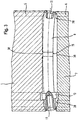
- Fig. 1 to 6 show a basic arrangement in plan view in an arrangement of the workpiece between the grinding wheel 1 and the regulating wheel 2 in a sectional course through the cutting planes 27 according to Fig. 7 ,
- Fig. 1 is disposed between the grinding wheel 1 and the regulating wheel 2, a shaft part 9, which has a curvature in exaggerated representation, so that in the central region of a maximum rounding error is present.
- Both the grinding wheel 1 and the regulating wheel 2 have at their lateral end portions profilings 3 and 4, which areas of larger diameter 5 of the grinding wheel 1 and larger diameter 6 of the regulating wheel 2 have.
- the diameters of the regions of increased diameter 5, 6 are dimensioned such that they are ground with them at the end regions of the shaft part 9, to which at the respective end faces centering 11 are introduced, before the grinding wheel 1 and the regulating wheel 2 in the region largest round impact of the shaft part 9 come into contact with this.
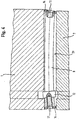
- a shaft part 9 to be ground is shown, which additionally has a collar, which is also used in this centerless grinding method is grinded from the outer diameter.
- a corresponding groove is provided in the grinding wheel 1 and also in the regulating wheel 2.
- the profiled areas 3, 4 of the grinding wheel 1 and the regulating wheel 2 according to the Fig. 2 to 6 are identical in dimensioning to the embodiment according to FIG Fig. 1 ,
- an additional profiling 30, which is a distance 13 for a support seat 15 to be ground (s.
- Fig. 3 trains.
- the distance 13 for the support seat is such that nevertheless first the end regions 28 of the shaft part 9 are ground by the profilings 3, 4 of the grinding wheel 1 and the regulating wheel 2, before the supporting seat 15 is ground by means of the profilings existing in the region of the greatest rounding error ,
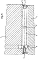
- Fig. 3 is the embodiment according to Fig. 2 shown, but the profiling 30 in the region of the largest round impact error of the shaft part on the grinding wheel 1 and the regulating wheel 2 have just come into engagement and the end portions 28 are at least partially ground on the shaft part 9 already.
- Fig. 4 shows a further embodiment according to the invention, in which the grinding wheel 1 and the regulating wheel 2 with respect to the dimensional and shape retention of the shaft part 9 have substantial areas of constant diameter. Both the grinding wheel 1 and the regulating wheel 2 thus have, except for the collar 12 on the shaft part 9 no profiling in their edge regions. Rather, the shaft part 9 is formed so that it has at its end regions in each case a collar, ie areas of larger diameter. According to Fig. 4 the workpiece 9 is also shown in an exaggerated manner with a curvature having a maximum rounding error approximately in its center. The grinding wheel 1 and the regulating wheel 2 are in the in Fig. 4 However, it is apparent that the intervention is imminent.
- the engagement initially takes place at the region of the collar, ie at the end regions of the shaft part 9, because there the distance between the grinding wheel 1 and the regulating wheel 2 is less than in the intermediate region, even in the region of the greatest rounding error of the shaft part 9.
- a further embodiment is shown, in which by the region of increased diameter, ie the collar 14 in the end region of the workpiece 9, a polished section, wherein as a situation just the engagement of grinding wheel 1 and regulating wheel 2 is shown.
- an area of increased diameter 31 on the shaft part ie a further collar is provided, which is suitable for grinding an additional support seat is provided.
- Such an additional support seat is useful above all when certain larger lengths of the workpiece, ie the shaft part are present.
- the area intended for the support seat is not ground yet. Only when a sufficiently strong bevel has taken place in the end regions of the shaft part 9, the grinding wheel 1 and the regulating wheel 2 will come into engagement with the central collar on the workpiece for grinding a support seat.
- Fig. 7 in side view, ie in a view in the direction of the longitudinal axes of the grinding wheel 1 and the regulating wheel 2, the arrangement of the distance between the grinding wheel and the regulating wheel including the arrangement of the shaft part 9 at this distance, that is shown in the grinding gap in conjunction with the support ruler 16.
- the wave-shaped part or the shaft part 9 is moved by engagement of the grinding wheel 1, which is driven in the direction of rotation 21, about its longitudinal axis 19 when resting on the support surface 24 of the support ruler 16 in the direction of rotation 23.
- the regulating wheel 2 is in its rotational direction 22 also in engagement with the shaft part 9 and thereby supports its rotation and forms together with the support surface 24 of the support ruler an abutment for introducing the grinding forces of the grinding wheel 1.
- the grinding wheel 1 rotates about its axis of rotation 17 and the regulating wheel 2 about its axis of rotation 18.
- the grinding wheel 1 is delivered in the feed direction 25, wherein the feed direction of the regulating wheel is characterized by the double arrow 26. Under delivery direction in each case a positive or negative feed direction is characterized, which is represented by the respective double arrows 25 and 26 respectively.
- the reference numeral 27, the cutting plane through the grinding wheel 1 and the regulating wheel 2 is shown, so that in the Fig. 1 to 6 shown distance refers to the related to the cutting planes 27 distance.
Landscapes
- Engineering & Computer Science (AREA)
- Mechanical Engineering (AREA)
- Grinding Of Cylindrical And Plane Surfaces (AREA)
- Grinding And Polishing Of Tertiary Curved Surfaces And Surfaces With Complex Shapes (AREA)
Description
Die Erfindung betrifft ein Verfahren zum Centerless-Schleifen von Wellenteilen, und zwar insbesondere von Rohren für gebaute Nockenwellen, wobei die Wellenteile zur Werkstücklängsachse konzentrisch verlaufende endseitige Zentrierbohrungen aufweisen.The invention relates to a method for centerless grinding of shaft parts, in particular of tubes for built camshafts, wherein the shaft parts to the workpiece longitudinal axis concentrically extending end-side centering holes have.
Üblicherweise wird beim Centerless-Schleifen das Werkstück zwischen Schleifscheibe und Regelscheibe auf einem Auflagelineal aufliegend und drehend geschliffen. Regelscheibe und Schleifscheibe bilden dabei einen Schleifspalt, der unten durch das Auflagelineal soweit verschlossen ist, dass das wellenförmige Werkstück durch eine linienförmige Berührung mit der Regelscheibe, der Schleifscheibe und der Stützfläche des Auflagelineals eingeschlossen ist und damit hinsichtlich seiner Längsachse lagefixiert ist und rotiert. Das Ziel dieser Anordnung ist eine möglichst ruhige Lage trotz Rotation und Unrundheit des ungeschliffenen Rohteils.Typically, in centerless grinding, the workpiece between the grinding wheel and regulating wheel is ground resting and rotating on a support ruler. Regulating wheel and grinding wheel thereby form a grinding gap which is closed down by the support ruler so far that the wave-shaped workpiece is enclosed by a linear contact with the regulating wheel, the grinding wheel and the support surface of the support ruler and is thus fixed in position with respect to its longitudinal axis and rotated. The aim of this arrangement is a quiet as possible position despite rotation and runout of the rough blank.
Das zu schleifende Rohteil unterliegt in aller Regel einer Vorbearbeitung, bevor es fertigbearbeitet wird. Nach der Vorbearbeitung weist das Rohteil Formfehler auf, insbesondere Geradheitsfehler bzw. Rundschlagfehler. Wird nun ein derartiges Werkstück mit Geradheitsfehlern einem Centerless-Schleifprozess unterzogen, so wird das Werkstück an der Stelle des höchsten Rundlaufschlages zuerst angeschliffen. Wegen derartiger Formfehler liegt das Werkstück beim Anschleifen nicht exakt auf dem Auflagelineal auf. Erst nach dem vollständigen Anschleifen des Werkstückes wird dieses im Schleifspalt im Wesentlichen in voller Länge auf dem Auflagelineal aufliegen und kann - wenn überhaupt - nun definiert und maß- und formgenau geschliffen werden.As a rule, the blank to be ground is subject to pre-processing before it is finished. After roughing, the blank has dimensional errors, in particular straightness errors or rounding errors. If such a workpiece with straightness errors is subjected to a centerless grinding process, the workpiece is first ground at the location of the highest concentricity impact. Because of such form errors, the workpiece is not exactly on the support ruler when grinding. Only after the complete grinding of the workpiece will this rest in the grinding gap substantially full length on the support ruler and can - if at all - now defined and cut to size and shape.
Häufig wird im Zuge der Vorbearbeitung an jeder Stirnseite des zu schleifenden Werkstückes eine Zentrierung eingebracht, welche auch als Zentrum bezeichnet wird. Diese Zentrierung soll die Längsachse des fertigen Werkstückes definieren, auf welche die sich der Vorbearbeitung anschließende Zwischen- und Fertigbearbeitung beziehen soll. Wenn nun die Werkstücke mit Maß- und Formfehlern aus der Verarbeitung mit herkömmlichen Centerless-Schleifverfahren geschliffen werden, so werden stets diese Fehler in der Auflage bzw. einer nicht in Längsrichtung kompletten Auflage des Werkstückes beim Anschleifen desselben auf das Fertigteil generell übertragen. Ziel beim Centerless-Schleifen muss jedoch sein, dass die vorhandenen Zentren am Werkstück nach dem Schleifen konzentrisch angeordnet sein sollen bzw. nur in sehr engen Toleranzen von dieser Konzentrizität abweichen. Beim bekannten Centerless-Schleifen ist es nicht möglich, beim Anschleifen eine gute Konzentrizität der Zentren nach dem Schleifen zu garantieren. Dies resultiert wegen der vorstehend genannten Probleme zum einen von der fehlerhaften Auflage des Werkstückes auf der Auflageschiene und zum anderen von den Fertigungsungenauigkeiten des Werkstückes aus der Vorbearbeitung.Often, in the course of pre-machining, centering is introduced on each end face of the workpiece to be ground, which is also referred to as the center. This centering is intended to define the longitudinal axis of the finished workpiece, to which the intermediate and finish machining subsequent to the pre-processing should relate. If now the workpieces with Dimensional and shape errors from the processing are ground with conventional centerless grinding, so these errors in the edition or a non-longitudinal complete edition of the workpiece when grinding it is always transferred to the finished part in general. The aim of centerless grinding, however, must be that the existing centers on the workpiece after grinding should be arranged concentrically or deviate from this concentricity only in very narrow tolerances. With the known centerless grinding, it is not possible to guarantee a good concentricity of the centers after grinding when grinding. This results because of the above-mentioned problems on the one hand by the faulty support of the workpiece on the support rail and the other by the manufacturing inaccuracies of the workpiece from the pre-processing.
Bei einem dem Centerless-Schleifen entlehnten, in DD 570 beschriebenen Verfahren liegt das Werkstück in einer prismenförmigen Nut durch einen auf jedem Schenkel des Auflageprismas vorhandenen linearen Kontakt an und wird mittels einer Andruckrolle im mittleren Bereich gehalten und in das Prisma gedrückt. Das bekannte Schleifverfahren beschreibt das Schleifen von zwei zapfenartigen Endbereichen des Werkstückes. Die Zapfen können nur dann eine ausreichende Konzentrizität aufweisen, wenn das Werkstück vorher genau konzentrisch geschliffen worden ist, d. h. gerade nicht in seiner Rohkontur belassen werden kann. Die im Endbereich vorhandenen Zapfen werden mittels einer Schleifscheibe geschliffen, ohne dass sich auf der der Schleifscheibe gegenüberliegenden Seite ein Widerlager befindet. Die heutzutage geforderte Konzentrizitätsgenauigkeit ist mit einem derartigen Verfahren nicht zu erreichen.In a centreless grinding borrowed method described in DD 570, the workpiece abuts in a prismatic groove through a linear contact present on each leg of the support prism and is held in the central region by a pinch roller and pressed into the prism. The known grinding method describes the grinding of two pin-like end portions of the workpiece. The pins can only have sufficient concentricity if the workpiece has previously been ground exactly concentric, d. H. just can not be left in its rough contour. The pins present in the end area are ground by means of a grinding wheel without an abutment on the side opposite the grinding wheel. The concentricity accuracy required today can not be achieved with such a method.
In
In
In
Die
Die Firma Mikrosa ist als Hersteller von Centerless-Schleifscheiben bekannt. Sie wendet ein Verfahren an, bei welchem zwischen sog. Hilfsspitzen das Werkstück angeschliffen wird und anschließend nach dem Lösen der Spitzen das Werkstück in der gleichen Schleifstation centerless auf einer Auflageschiene aufliegend zwischen der Schleifscheibe und der Regelscheibe fertiggeschliffen wird. Sowohl der technische Aufbau als auch die Ausrichtung der Spitzen erfordern einen relativ großen Aufwand, und das Komplettsystem ist bzgl. der Genauigkeit nur schwer beherrschbar.Mikrosa is known as a manufacturer of centerless grinding wheels. It uses a method in which between so-called auxiliary tips the workpiece is ground and then after the loosening of the tips the workpiece in the same grinding station centerless on a support rail resting between the grinding wheel and the regulating wheel is finished. Both the technical structure and the alignment of the tips require a relatively large effort, and the complete system is difficult to control in terms of accuracy.
Demgegenüber liegt die Aufgabe der vorliegenden Erfindung darin, ein Verfahren zum Centerless-Schleifen von Wellenteilen, insbesondere von Rohren für gebaute Nockenwellen, mit welchem Formfehler eines Wellenrohteils aus dessen Vorbearbeitung sich in deutlich geringerem Maße auf die Genauigkeit des fertigen Wellenteils auswirken, als das bei bekannten Verfahren der Fall ist, mithin sich also eine höhere Genauigkeit des fertiggeschliffenen Wellenteils erzielen lässt.In contrast, the object of the present invention is a method for centerless grinding of shaft parts, in particular of tubes for built camshafts, with which form error of a Wellenrohteils from the pre-processing to a much lesser extent affect the accuracy of the finished shaft part, than that in known The method is the case, therefore, therefore, a higher accuracy of the finished ground shaft part can be achieved.
Diese Aufgabe wird durch ein Verfahren mit den Merkmalen gemäß Anspruch 1 gelöst. Zweckmäßige Weiterbildungen sind in den abhängigen Ansprüchen definiert.This object is achieved by a method having the features according to
Bei dem erfindungsgemäßen Verfahren sollen insbesondere Nockenwellenrohre so geschliffen werden, dass nur noch ein minimaler Konzentrizitätsfehler auftritt, und zwar soll eine solch hohe Konzentrizität erreicht werden, welche mit bekannten Centerless-Schleifverfahren nicht erreicht werden kann.In the method according to the invention, in particular camshaft tubes are to be ground so that only a minimal concentricity error occurs, namely, such a high concentricity should be achieved, which can not be achieved with known centerless grinding methods.
Der der vorliegenden Erfindung zugrunde liegende Grundgedanke besteht darin, dass das zu schleifende Wellenteil an seinen Enden zuerst im Centerless-Schleifverfahren angeschliffen wird, ohne dass die Schleif- und die Regelscheibe an den Stellen des höchsten Rundlaufschlages des wellenförmigen Teils diese bereits anschleifen. Dadurch ist es möglich, dass das Wellenteil genau in dem Bereich zuerst angeschliffen wird, in welchem sich Zentrierungen finden. Dadurch wird erreicht, dass die Anschleifzonen des Wellenteils sich genau über dem Zentrum, d. h. der jeweiligen Zentrierung an den Enden des Wellenteils befinden, so dass bzgl. des jeweiligen Zentrums ein zentrisches Anschleifen des Wellenteils erreicht werden kann, so dass an den Enden des Wellenteils eine hohe Konzentrizität des Wellenteils erreicht wird.The basic idea on which the present invention is based is that the shaft part to be ground is first sanded at its ends in the centerless grinding method, without the grinding and regulating disks already grinding at the points of the highest concentricity of the wave-shaped part. This makes it possible for the shaft part to be ground first in the area in which centerings are found. This ensures that the grinding zones of the shaft part are located exactly above the center, d. H. the respective centering at the ends of the shaft part, so that with respect to the respective center a centric grinding of the shaft part can be achieved, so that at the ends of the shaft part, a high concentricity of the shaft part is achieved.
Bei dem erfindungsgemäßen Verfahren zum Centerless-Schleifen von Wellenteilen, welche insbesondere Rohre für gebaute Nockenwellen sind, werden, wie das üblicherweise beim Centerless-Schleifen erfolgt, zu schleifende Wellenteile, welche an ihren Stirnseiten axiale Zentrierungen aufweisen, zwischen einer Schleifscheibe und einer Regelscheibe drehend angetrieben geschliffen. Die Schleifscheibe und die Regelscheibe weisen eine Breite auf, welche zumindest der Länge des Wellenteils entspricht. Dies bedeutet, dass die Schleifscheibe und die Regelscheibe eine solche Breite aufweisen, welche zumindest gerade der Länge des Wellenteils entspricht. Es ist jedoch sogar üblich, dass die Breite der Schleifscheibe in der Regelscheibe etwas größer als die Länge des Wellenteils ist. Bei üblicher Anordnung beim Centerless-Schleifen von Wellenteilen weisen die Schleifscheibe und die Regelscheibe in radialer Richtung einen radialen Abstand zueinander im Bereich der Enden des Wellenteils auf, welcher geringer ist als im Bereich zwischen den Endbereichen des Wellenteils, d. h. im sog. Zwischenbereich. Der zum Schleifen des Wellenteils erforderliche Schleifspalt wird also - in axialer Richtung der Schleifscheibe und der Regelscheibe gesehen - zwischen der Schleifscheibe und der Regelscheibe definiert und ist nach unten durch ein Auflagelineal begrenzt. Der Abstand zwischen der Schleifscheibe und der Regelscheibe in radialer Richtung ist im Bereich der Enden des Wellenteils geringer als der Abstand im Zwischenbereich zwischen den Endbereichen des Wellenteils. Dadurch werden die Endbereiche des Wellenteils zuerst angeschliffen. Daran schließt sich das Anschleifen des zwischen den Endbereichen liegenden Zwischenbereiches an, gefolgt von einem maß- und formhaltigen Schleifen des kompletten Wellenteils auf Endmaß, und zwar auf Basis der konzentrisch zu den Zentrierungen ausgeführten, auf einem Auflagelineal aufliegenden Anschliffe an den Endbereichen des Wellenteils. Nachdem die Endbereiche geschliffen worden sind, schließt sich das maß- und formhaltige Schleifen des kompletten Wellenteils an, welches auf Basis der konzentrisch zu den Zentrierungen ausgeführten Anschliffe an den Endbereichen des Wellenteils selbst bei normalerweise stets vorhandenem Rundschlag bei länglichen wellenförmigen Bauteilen dadurch zu einer höheren Konzentrizität zu den Zentrierungen an den Endbereichen führt, als das beim herkömmlichen Centerless-Schleifen der Fall ist.In the method according to the invention for centerless grinding of shaft parts, which are in particular tubes for built-up camshafts, are, as is usually the case in centerless grinding takes place, to be ground shaft parts, which have axial centering on their front sides, ground between a grinding wheel and a regulating wheel driven in rotation. The grinding wheel and the regulating wheel have a width which corresponds at least to the length of the shaft part. This means that the grinding wheel and the regulating wheel have a width which corresponds at least exactly to the length of the shaft part. However, it is even common that the width of the grinding wheel in the regulating wheel is slightly larger than the length of the shaft part. In conventional arrangement in centerless grinding of shaft parts, the grinding wheel and the regulating wheel in the radial direction at a radial distance from one another in the region of the ends of the shaft part, which is less than in the region between the end portions of the shaft part, ie in the so-called. The required for grinding the shaft part grinding gap is thus - seen in the axial direction of the grinding wheel and the regulating wheel - defined between the grinding wheel and the regulating wheel and is bounded below by a support ruler. The distance between the grinding wheel and the regulating wheel in the radial direction is less in the region of the ends of the shaft part than the distance in the intermediate region between the end regions of the shaft part. As a result, the end portions of the shaft part are first ground. This is followed by the grinding of the intermediate region located between the end regions, followed by a dimensionally and form-wise grinding of the entire shaft part to final dimension, on the basis of concentric with the centering, resting on a support ruler poles at the end portions of the shaft portion. After the end portions have been ground, the dimensional and shape-retaining grinding of the entire shaft part joins, which on the basis of the concentric to the centerings polished on the end portions of the shaft part even with normally always present rounding at elongated wave-shaped components thereby to a higher concentricity leads to the centerings at the end areas, as is the case with conventional centerless grinding.
Unter radialem Abstand zwischen der Schleifscheibe und der Regelscheibe wird nicht zwingend der geringste Abstand in radialer Richtung zwischen der Regelscheibe und der Schleifscheibe verstanden, sondern ein Abstand ober- und unterhalb einer beide Längsachsen der Schleifscheibe und der Regelscheibe aufweisenden Ebene, in welchem das wellenförmige Werkstück angeordnet und nach unten durch das Auflagelineal im Schleifspalt gehalten wird. Die geometrischen Verhältnisse für ein derartiges Centerless-Schleifen sind in prinzipieller Anordnung in
Gemäß einem ersten Ausführungsbeispiel sind die Schleifscheibe und die Regelscheibe so ausgebildet, dass sie an ihren Seiten, welche beim Schleifen des Wellenteils dessen Endbereichen entsprechen, profiliert sind und einen größeren Durchmesser aufweisen als im zwischen den Endbereichen liegenden Zwischenbereich. Durch den jeweils größeren Durchmesser in den Bereichen, welche den Endbereichen des Wellenteils entsprechen, ist ein kleinerer Abstand zwischen Schleifscheibe und Regelscheibe vorhanden als im Zwischenbereich, so dass beim Schleifen zuerst die Endbereiche des Wellenteils geschliffen werden. Die Bereiche größeren Durchmessers der Schleifscheibe und der Regelscheibe weisen dabei einen derartigen Durchmesser auf, dass in der Tat zuerst die Endbereiche am Wellenteil geschliffen werden, bevor die Schleifscheibe und die Regelscheibe im Bereich des größten Rundschlags des Wellenteils mit diesem in Eingriff gelangt. Durch dieses Herstellen der Anschliffe an den Endbereichen des Wellenteils durch die Bereiche größeren Durchmessers der Schleifscheibe und der Regelscheibe werden die Anschliffe konzentrisch zu den axialen Zentrierungen des Wellenteils hergestellt und dienen für das nachfolgende maß- und formhaltige Schleifen sozusagen als Basis. Dadurch wird ein verbessertes Schleifergebnis am Werkstück erzielt.According to a first embodiment, the grinding wheel and the regulating wheel are formed so that on their sides, which during grinding of the shaft part of its end portions correspond, are profiled and have a larger diameter than in the lying between the end regions intermediate area. Due to the respective larger diameter in the areas corresponding to the end portions of the shaft part, a smaller distance between grinding wheel and regulating wheel is present than in the intermediate region, so that during grinding first the end portions of the shaft part are ground. The areas of larger diameter of the grinding wheel and the regulating wheel in this case have such a diameter that in fact first the end portions are ground on the shaft portion before the grinding wheel and the regulating wheel in the region of the largest rounding of the shaft part engages with this. As a result of this production of the polished sections on the end regions of the shaft part through the regions of larger diameter of the grinding wheel and the regulating wheel, the polished sections are produced concentrically with the axial centering of the shaft part and serve as a basis for the subsequent dimensional and shape-based grinding. This achieves an improved grinding result on the workpiece.
Gemäß einem zweiten Ausführungsbeispiel ist es jedoch auch möglich, dass das im erfindungsgemäßen Centerless-Schleifen verwendete Wellenteil in seinen Endbereichen jeweils einen Bereich vergrößerten Durchmessers, vorzugsweise in Form eines Kragens, aufweist, wodurch ebenfalls zunächst die Anschliffe an den Endbereichen des Wellenteils mit verbesserter Konzentrizität zu den axialen Zentrierungen hergestellt werden. Dies wird jedoch nur erreicht, wenn der Bereich vergrößerten Durchmessers jeweils einen solchen Durchmesser aufweist, dass zunächst der Eingriff der Schleifscheibe und der Regelscheibe nur an den Anschliffen an den Endbereichen des Wellenteils erfolgt, ohne dass bereits im Bereich des größten Rundschlagfehlers des Wellenteils geschliffen wird. Das bedeutet, dass die Schleifscheibe und die Regelscheibe in ihren, den Zwischenbereichen des Wellenteils entsprechenden Bereichen solche Durchmesser aufweisen, dass die Endbereiche des Wellenteils zuerst angeschliffen werden.According to a second embodiment, however, it is also possible that the shaft portion used in centerless grinding according to the invention each have an area of increased diameter, preferably in the form of a collar in its end regions, which also first to the ground portions of the shaft portion with improved concentricity to the axial centerings are produced. However, this is only achieved if the region of increased diameter has a diameter such that initially the engagement of the grinding wheel and the regulating wheel takes place only on the polished sections on the end regions of the shaft part, without grinding already in the region of the greatest rounding error of the shaft part. This means that the grinding wheel and the regulating wheel in their areas corresponding to the intermediate areas of the shaft part have such diameters that the end areas of the shaft part are first ground.
Um die Genauigkeit bzw. Konzentrizität des Wellenteils nach dem Schleifen noch weiter zu verbessern, ist bei Wellenteilen mit einer gewissen größeren Länge gemäß einem weiteren Ausführungsbeispiel vorgesehen, dass die Schleifscheibe und die Regelscheibe im zwischen den Endbereichen des Wellenteils liegenden Zwischenbereich, insbesondere in der Mitte, einen Bereich größeren Durchmessers aufweisen, mittels welchem neben den Anschliffen an den Endbereichen ein ebenfalls zu den Zentrierungen konzentrischer Stützsitz an dem Wellenteil angeschliffen wird. Vorzugsweise ist dieser zu schleifende Stützsitz im Bereich des maximalen Rundschlagfehlers des Wellenteils angeordnet. Dieser Stützsitz wird vorzugsweise dadurch geschliffen, dass die Schleifscheibe und die Regelscheibe jeweils in diesem Bereich einen Bereich vergrößerten Durchmessers aufweisen. Analog zu dem Schleifen der Endbereiche des Wellenteils und den dementsprechend ausgebildeten profilierten Seitenbereichen der Schleifscheibe und der Regelscheibe oder dem vergrößerten Durchmesser in den Endbereichen des Wellenteils kann gemäß einer Weiterbildung auch das Wellenteil selbst vorzugsweise in seinem Mittelbereich bzw. Zwischenbereich einen Bereich vergrößerten Durchmessers aufweisen, welcher zunächst entweder zeitgleich mit dem Schleifen der Endbereiche oder nach diesem mit der Schleifscheibe und der Regelscheibe in Kontakt gelangt.In order to further improve the accuracy or concentricity of the shaft part after grinding, it is provided in shaft parts with a certain greater length according to a further embodiment that the grinding wheel and the regulating wheel are located in the intermediate region lying between the end regions of the shaft part, in particular in the middle, have a region of larger diameter, by means of which in addition to the polished sections at the end regions, a likewise concentric to the centering support seat is ground to the shaft part. Preferably, this supporting seat to be ground is arranged in the region of the maximum rounding error of the shaft part. This support seat is preferably ground by the fact that the grinding wheel and the regulating wheel each have an area of increased diameter in this area. Analogous to the grinding of the end regions of the shaft part and the correspondingly formed profiled side regions of the grinding wheel and the regulating wheel or the enlarged diameter in the end regions of the shaft part, according to a development, the shaft part itself preferably has in its central region or intermediate region a region of increased diameter, which initially either coincides with the grinding of the end regions or after this comes into contact with the grinding wheel and the regulating wheel.
Vorzugsweise ist es auch möglich, dass je nach Länge des zu schleifenden Wellenteils noch ein weiterer konzentrischer Stützsitz oder noch weitere konzentrische Stützsitze angeschliffen werden.Preferably, it is also possible that, depending on the length of the shaft part to be ground still another concentric support seat or even more concentric support seats are sanded.
Gemäß dem erfindungsgemäßen Verfahren werden bei Vorhandensein eines Stützsitzes am Wellenteil zunächst die Endbereiche des Wellenteils und anschließend entweder der Stützsitz oder die Stützsitze angeschliffen und danach das Wellenteil in seiner gesamten Länge geschliffen, oder die Endbereiche und der Stützsitz bzw. die Stützsitze werden gleichzeitig angeschliffen.According to the method of the invention, the end portions of the shaft portion and then either the support seat or the support seats are sanded in the presence of a support seat on the shaft part and then ground the shaft part in its entire length, or the end portions and the support seat or the support seats are sanded simultaneously.
Die Dimensionierung des Abstandes, d. h. die Profilierung von Schleif- und Regelscheibe bzw. die Abmessungen des Wellenteils, entweder an den Endbereichen des Wellenteils oder in dessen Mittelbereich ist dabei so ausgelegt, dass dieser Abstand so gering ist, dass zunächst ein Schleifen an den Endbereichen und erst danach ein Schleifen im Bereich des größten Rundlaufschlages des Wellenteils erfolgt, was bevorzugt selbst bei Vorhandensein eines zwischen den Endbereichen angeordneten Stützsitzes möglich ist.The dimensioning of the distance, d. H. the profiling of grinding and regulating wheel or the dimensions of the shaft part, either at the end portions of the shaft part or in the central region is designed so that this distance is so small that initially a grinding at the end and only then a grinding in the area the largest concentricity of the shaft part takes place, which is preferably possible even in the presence of a arranged between the end regions support seat.
Gemäß einer Weiterbildung der Erfindung sind die Schleifscheibe und die Regelscheibe in dem Zwischenbereich, welcher beim zu schleifenden Wellenteil zwischen dessen Endbereichen liegt, in einem geringen Maße profiliert. Diese geringe Profilierung beinhaltet eine solche Anzahl von jeweiligen Nuten sowohl in der Schleifscheibe als auch in der Regelscheibe, wie am fertigen Wellenteil Sitze für Bauteile, insbesondere Nocken, benötigt werden. Derartige Nockensitze stellen keine Stützsitze im Sinne der vorliegenden Erfindung dar und weisen lediglich eine geringe Durchmesservergrößerung von bspw. ca. 0,02 - 0,05 mm gegenüber dem restlichen Bereich des Nockenwellenteils auf. Ein derartiges, Nockensitze zur Befestigung von jeweiligen Nocken aufweisendes Wellenteil wird aber ansonsten ebenso nach dem erfindungsgemäßen Verfahren centerless geschliffen, so dass sich ein gegenüber den mit bekannten Centerless-Schleifen geschliffenes Wellenteil eine erhöhte, d. h. verbesserte Konzentrizität zu den axialen Zentrierungen aufweist. Diese höhere Genauigkeit der Konzentrizität des Nockenwellengrundkörpers führt zu verbesserten Lauf- und Einsatzbedingungen der fertigen gebauten Nockenwelle in den jeweiligen Motoren.According to one embodiment of the invention, the grinding wheel and the regulating wheel in the intermediate region, which lies between the end regions of the shaft part to be ground, are profiled to a small extent. This low profiling includes such a number of respective grooves in both the grinding wheel and the regulating wheel as seats on components, in particular cams, are needed on the finished shaft part. Such cam seats do not constitute support seats in the sense of the present invention and only have a small increase in diameter of, for example, approximately 0.02-0.05 mm relative to the remaining area of the camshaft part. However, such a cam seats for fastening of respective cams exhibiting shaft part is otherwise centerless also ground according to the method of the invention, so that compared to the ground with known Centerless loops shaft part has an increased, ie improved concentricity to the axial centerings. This higher accuracy of concentricity of the camshaft body leads to improved running and operating conditions of the finished assembled camshaft in the respective engines.
Weitere Vorteile und spezielle Details von konkreten Ausgestaltungen des erfindungsgemäßen Verfahrens bzw. des erfindungsgemäßen Schleifscheiben- und Regelscheibenpaares werden nun anhand der nachfolgenden Zeichnungen beschrieben. In den Zeichnungen zeigen:
- Fig. 1
- eine prinzipielle Anordnung von Schleifscheibe und Regelscheibe mit einem einen Rundschlagfehler aufweisenden Wellenteil, welches in seinen Endbereichen durch entsprechend an den Seiten profilierte Schleifscheiben und Regelscheiben zuerst angeschliffen wird;
- Fig. 2
- eine Anordnung wie in
Fig. 1 , jedoch mit einer zusätzlichen Profilierung im Zwischenbereich zwischen den Endbereichen zur Erzeugung eines für einen Stützsitz dienenden weiteren Anschliffes, welcher im Bereich des größten Rundschlages noch nicht in Kontakt mit dem Wellenteil gelangt ist; - Fig. 3
- eine Anordnung gemäß
Fig. 2 , bei welcher im Bereich des größten Rundschlagfehlers des Wellenteils der Kontakt zur Schleifscheibe gerade eingetreten ist; - Fig. 4
- ein Ausführungsbeispiel, bei welchem Schleifscheibe und Regelscheibe einen im Wesentlichen konstanten Durchmesser aufweisen, das Wellenteil jedoch an seinen Endbereichen jeweils einen Bereich vergrößerten Durchmesser aufweist, welcher für einen erfindungsgemäßen Anschliff vorgesehen ist;
- Fig. 5
- ein Ausführungsbeispiel gemäß
Fig. 4 , bei welchem mittels Schleifscheibe und Regelscheibe im jeweiligen Endbereich des Wellenteils bei dort vorhandenem, größerem Durchmesser des Wellenteils der Anschliff erfolgt, wobei zusätzlich im Bereich des größten Rundschlagfehlers ein Bereich vergrößerten Durchmessers am Werkstück vorhanden ist, welcher für die Erzeugung eines Anschliffes für einen Stützsitz vorgesehen ist; - Fig. 6
- die Ausgestaltung gemäß
Fig. 5 , wobei jedoch der für den Stützsitz vorgesehene Bereich vergrößerten Durchmessers am Werkstück gerade ebenfalls angeschliffen wird; und - Fig.7
- in axialer Richtung der Schleifscheibe und der Regelscheibe die prinzipielle Anordnung des Schleifspaltes mit der Darstellung des Abstandes zwischen der Schleifscheibe und der Regelscheibe im Schleifspalt beim untermittigen Schleifen und Abstützung durch ein Auflagelineal.
- Fig. 1
- a basic arrangement of grinding wheel and regulating wheel with a round impact error having shaft portion which is first ground in its end by corresponding profiled on the sides grinding wheels and regulating wheels;
- Fig. 2
- an arrangement as in
Fig. 1 , but with an additional profiling in the intermediate region between the end regions for generating a further bevel serving for a support seat, which has not yet come into contact with the shaft part in the region of the largest round impact; - Fig. 3
- an arrangement according to
Fig. 2 in which contact with the grinding wheel has just occurred in the region of the greatest rounding error of the shaft part; - Fig. 4
- an embodiment in which the grinding wheel and regulating wheel have a substantially constant diameter, the shaft part, however, at its end regions in each case an area enlarged diameter, which is provided for a bevel according to the invention;
- Fig. 5
- an embodiment according to
Fig. 4 in which by means of grinding wheel and regulating wheel in the respective end region of the shaft part there existing, larger diameter of the shaft part, the polished section, wherein additionally in the region of the largest rounding error, a region of increased diameter on the workpiece is provided, which provided for the production of a bevel for a supporting seat is; - Fig. 6
- the embodiment according to
Fig. 5 wherein, however, the area provided for the support seat enlarged diameter of the workpiece is also just sanded; and - Figure 7
- in the axial direction of the grinding wheel and the regulating wheel, the basic arrangement of the grinding gap with the representation of the distance between the grinding wheel and the regulating wheel in the grinding gap at the bottom grinding and support by a support ruler.
Die
In
Sowohl in
In
In
Diese Situation ist in
In vereinfachter Darstellung ist in
Mit dem erfindungsgemäßen Verfahren ist es möglich, eine höhere Konzentrizität eines wellenförmigen Teils bezogen auf die an den Endbereichen vorhandenen axialen Zentrierungen zu erzeugen. Das Verfahren verhindert erfindungsgemäß, dass sich der bei Wellenteilen in der Regel stets vorhandene Rundschlagfehler negativ auf die Rundlaufgenauigkeit bzw. Konzentrizität des fertigen Bauteils auswirkt.With the method according to the invention it is possible to produce a higher concentricity of a wave-shaped part relative to the axial centerings present at the end regions. The method prevents according to the invention that the rounding error which generally always exists in the case of shaft parts has a negative effect on the concentricity or concentricity of the finished component.
- 11
- Schleifscheibegrinding wheel
- 22
- RegelscheibeRegulating wheel
- 33
- Profilierung der SchleifscheibeProfiling the grinding wheel
- 44
- Profilierung der RegelscheibeProfiling the regulating wheel
- 55
- Bereich größeren Durchmessers der SchleifscheibeArea of larger diameter of the grinding wheel
- 66
- Bereich größeren Durchmessers der RegelscheibeArea of larger diameter of the regulating wheel
- 77
- Abstand zwischen Schleifscheibe und Regelscheibe im Endbereich des WellenteilsDistance between grinding wheel and regulating wheel in the end area of the shaft part
- 88th
- Abstand zwischen Schleifscheibe und Regelscheibe im Zwischenbereich des WellenteilsDistance between grinding wheel and regulating wheel in the intermediate area of the shaft part
- 99
- Wellenteil/WerkstückShaft part / workpiece
- 1010
- Längsachse/WerkstückLongitudinal axis / workpiece
- 1111
- Zentrierung im Endbereich des WellenteilsCentering in the end of the shaft part
- 1212
- Bund am WellenteilCovenant on the shaft part
- 1313
- Abstand zwischen Schleifscheibe und Regelscheibe für StützsitzDistance between grinding wheel and regulating wheel for support seat
- 1414
- Kragen im Endbereich des WellenteilsCollar in the end of the shaft part
- 1515
- Stützsitz am WellenteilSupport seat on the shaft part
- 1616
- Auflagelinealedition ruler
- 1717
- Drehachse SchleifscheibeRotary axis grinding wheel
- 1818
- Drehachse RegelscheibeRotary axis regulating wheel
- 1919
- Drehachse WellenteilRotary shaft shaft part
- 2121
- Drehrichtung SchleifscheibeDirection of rotation grinding wheel
- 2222
- Drehrichtung RegelscheibeDirection of rotation regulating wheel
- 2323
- Drehrichtung WellenteilDirection of rotation shaft part
- 2424
- Auflagefläche auf AuflagelinealSupport surface on support ruler
- 2525
- Zustellrichtung SchleifscheibeInfeed direction grinding wheel
- 2626
- Zustellrichtung RegelscheibeFeed direction regulating wheel
- 2727
- Schnittebenecutting plane
- 2828
- Endbereichend
- 2929
- Zwischenbereichintermediate area
- 3030
- zusätzliche Profilierung an Schleif- und an Regelscheibe für Stützsitzadditional profiling on grinding and regulating wheel for support seat
- 3131
- Bereich größeren Durchmessers am Wellenteil für StützsitzArea of larger diameter on the shaft part for support seat
Claims (8)
- Method for the centreless grinding of shaft parts (9), in particular of tubes for assembled camshafts, in which the shaft part (9) to be ground, having axial centring means (11) at its ends, driven in rotation at a distance (7, 8) between grinding wheel (1) and regulating wheel (2), is ground, the grinding wheel (1) and the regulating wheel (2) each having a width which corresponds at least to the length of the shaft part (9) and ground portions formed concentrically with the centring means (11) are firstly ground on the shaft part (9) in its end regions (28),
which is followed by the grinding of the intermediate region (29) located between the end regions (28), followed by a dimension- and shape-maintaining grinding of the complete shaft part (9) to the final dimension on the basis of the ground portions made concentrically with the centring means (11), resting on a supporting straightedge (16) on the end regions (28) of the shaft part (9). - Method according to Claim 1, in which the shaft part (9) is ground in its end regions (28) by the grinding wheel (1) and regulating wheel (2) each having a larger diameter there, at a smaller distance (7) between the grinding wheel and the regulating wheel, which distance is formed as a result in the regions corresponding to the end regions of the shaft part.
- Method according to Claim 1, in which the shaft part (9) has in its end regions (28) a respective region of larger diameter formed as a collar (14), and the grinding wheel (1) and the regulating wheel (2) have diameters in their regions corresponding to the intermediate regions (29) of the shaft part (9) such that the collar (14) of the shaft part (9) is ground first.
- Method according to Claim 1 or 2, in which the grinding wheel (1) and the regulating wheel (2) each have a region of greater diameter (30) in the intermediate region (29) located between the end regions (28), in particular in the middle, by means of which at least one supporting seat (15) that is concentric with the centring means (11) is ground on the shaft part (9).
- Method according to Claim 4, in which the end regions (28) of the shaft part (9) are ground first, then the at least one supporting seat (15) is ground and after that the shaft part (9) is ground over its entire length.
- Method according to Claim 4, in which the end regions (28) and the at least one supporting seat (15) are ground simultaneously.
- Method according to Claim 2, in which the smaller distance (7) provided in the end regions (28) of the shaft part (9) has a value such that grinding on a maximum run-out of the shaft part (9) present in the region between the end regions (28) is started at the earliest after the grinding of the end regions (28) of the shaft part (9) has been carried out.
- Method according to one of Claims 3 to 7, in which the collar (14) present in the end regions (28) of the shaft part (9) has a diameter such that grinding on the maximum run-out of the shaft part (9) present in the intermediate region (29) between the end regions (28) is started at the earliest after the grinding of the end regions (28) of the shaft part (9) has been carried out.
Applications Claiming Priority (2)
| Application Number | Priority Date | Filing Date | Title |
|---|---|---|---|
| DE102013214226.9A DE102013214226B4 (en) | 2013-07-19 | 2013-07-19 | METHOD FOR CENTERLESS GRINDING OF SHAFT PARTS, PARTICULARLY TUBES FOR BUILT-IN CAM WAVES, AND PROCESSED GRINDING WHEEL AND PULLEY PAD |
| PCT/EP2014/062525 WO2015007444A1 (en) | 2013-07-19 | 2014-06-16 | Method for the centreless grinding of shaft parts, in particular of tubes for assembled camshafts, and grinding-wheel and regulating-wheel pair provided for this purpose |
Publications (2)
| Publication Number | Publication Date |
|---|---|
| EP3022014A1 EP3022014A1 (en) | 2016-05-25 |
| EP3022014B1 true EP3022014B1 (en) | 2019-10-23 |
Family
ID=50976627
Family Applications (1)
| Application Number | Title | Priority Date | Filing Date |
|---|---|---|---|
| EP14731228.4A Active EP3022014B1 (en) | 2013-07-19 | 2014-06-16 | Method for the centreless grinding of shaft parts, in particular of tubes for assembled camshafts |
Country Status (7)
| Country | Link |
|---|---|
| US (1) | US9878417B2 (en) |
| EP (1) | EP3022014B1 (en) |
| CN (1) | CN105392596B (en) |
| DE (1) | DE102013214226B4 (en) |
| ES (1) | ES2765207T3 (en) |
| RU (1) | RU2660943C2 (en) |
| WO (1) | WO2015007444A1 (en) |
Families Citing this family (1)
| Publication number | Priority date | Publication date | Assignee | Title |
|---|---|---|---|---|
| DE102015206082A1 (en) | 2015-04-02 | 2016-10-06 | Mahle International Gmbh | grinding machine |
Citations (1)
| Publication number | Priority date | Publication date | Assignee | Title |
|---|---|---|---|---|
| JP2004167610A (en) * | 2002-11-18 | 2004-06-17 | Isobe Seiko Kk | Method for continuously grinding a large number of cylindrical parts and grinding device |
Family Cites Families (18)
| Publication number | Priority date | Publication date | Assignee | Title |
|---|---|---|---|---|
| DD570A (en) | ||||
| US1640993A (en) * | 1925-05-26 | 1927-08-30 | Einar A Hanson | Metal-working machine |
| US2280620A (en) * | 1939-02-28 | 1942-04-21 | Cincinnati Grinders Inc | Apparatus for finishing tubular articles |
| US2525591A (en) * | 1945-01-18 | 1950-10-10 | Louis M Cotchett | Top roll for textile drafting mechanisms |
| US3108411A (en) * | 1961-10-26 | 1963-10-29 | D Errico Pasquale | Attachment for centerless grinder |
| DE1293640B (en) | 1964-11-27 | 1969-09-11 | Method and device for grinding centering cones. Anise: Aktietoolaget Malcus Holmquist, Halmstad (Sweden) | |
| US4009538A (en) * | 1975-01-08 | 1977-03-01 | John Hanecker | Fixture for converting a centerless grinder to a center grinder |
| DD119009A1 (en) | 1975-04-29 | 1976-04-05 | ||
| JPS56157939A (en) * | 1980-05-12 | 1981-12-05 | Honda Motor Co Ltd | Crankshaft work processor |
| SU963814A1 (en) * | 1981-03-31 | 1982-10-07 | Московский Автомобильный Завод Им.И.А.Лихачева (Производственное Объединение Зил) | Apparatus for centre-less grinding of stepped-diameter shafts |
| JPS6025640A (en) * | 1983-07-21 | 1985-02-08 | Toyoda Mach Works Ltd | Forming method of stepped shaft |
| JPH0413075Y2 (en) * | 1987-11-18 | 1992-03-27 | ||
| JPH11322113A (en) * | 1998-05-11 | 1999-11-24 | Suncall Corp | Skew suppressing type feed roller and centerless grinding device |
| JP2000263395A (en) * | 1999-03-11 | 2000-09-26 | Noritake Diamond Ind Co Ltd | Centerless grinding blade |
| DE10308292B4 (en) * | 2003-02-26 | 2007-08-09 | Erwin Junker Maschinenfabrik Gmbh | Method of cylindrical grinding in the manufacture of tools made of hard metal and cylindrical grinding machine for grinding cylindrical starting bodies in the manufacture of tools made of hard metal |
| JP5173592B2 (en) * | 2008-05-24 | 2013-04-03 | 光洋機械工業株式会社 | Method of bending cylindrical workpiece, centerless grinding method and apparatus |
| CN101704204A (en) * | 2009-11-12 | 2010-05-12 | 杭州劳格罗拉轴承滚子有限公司 | Noncentral penetrated super-finishing method of spherical roller |
| DE102010010758B4 (en) | 2010-03-09 | 2014-03-06 | Erwin Junker Grinding Technology A.S. | Centerless cylindrical grinding machine for grinding bar-shaped workpieces and method for centerless cylindrical grinding of bar-shaped workpieces |
-
2013
- 2013-07-19 DE DE102013214226.9A patent/DE102013214226B4/en active Active
-
2014
- 2014-06-16 WO PCT/EP2014/062525 patent/WO2015007444A1/en not_active Ceased
- 2014-06-16 RU RU2016102744A patent/RU2660943C2/en active
- 2014-06-16 CN CN201480040728.5A patent/CN105392596B/en active Active
- 2014-06-16 US US14/903,202 patent/US9878417B2/en active Active
- 2014-06-16 EP EP14731228.4A patent/EP3022014B1/en active Active
- 2014-06-16 ES ES14731228T patent/ES2765207T3/en active Active
Patent Citations (1)
| Publication number | Priority date | Publication date | Assignee | Title |
|---|---|---|---|---|
| JP2004167610A (en) * | 2002-11-18 | 2004-06-17 | Isobe Seiko Kk | Method for continuously grinding a large number of cylindrical parts and grinding device |
Also Published As
| Publication number | Publication date |
|---|---|
| ES2765207T3 (en) | 2020-06-08 |
| RU2660943C2 (en) | 2018-07-11 |
| EP3022014A1 (en) | 2016-05-25 |
| RU2016102744A (en) | 2017-08-01 |
| US20160151875A1 (en) | 2016-06-02 |
| DE102013214226A1 (en) | 2015-01-22 |
| CN105392596B (en) | 2017-06-16 |
| RU2016102744A3 (en) | 2018-03-13 |
| US9878417B2 (en) | 2018-01-30 |
| WO2015007444A1 (en) | 2015-01-22 |
| DE102013214226B4 (en) | 2018-06-21 |
| CN105392596A (en) | 2016-03-09 |
Similar Documents
| Publication | Publication Date | Title |
|---|---|---|
| EP3274120B1 (en) | Method and device for precision-machining toothed and hardened work wheels | |
| EP2167277B1 (en) | Grinding center and method for simultaneous grinding of a plurality of bearings and end-side surfaces of crankshafts | |
| DE10144649C5 (en) | Method for twist-free machining of rotationally symmetrical surfaces | |
| EP2759364B1 (en) | Tool for grinding toothed work pieces with collision contour | |
| EP2167275B1 (en) | Grinding center and method for the simultaneous grinding of multiple crankshaft bearings | |
| DE10144644B4 (en) | Method and device for grinding centric bearing points of crankshafts | |
| DE102011113757B4 (en) | Method and device for finishing workpieces | |
| EP0497008B1 (en) | Process and apparatus for grinding cams or the like | |
| DE19919893A1 (en) | Pre- and finish grinding a crankshaft in one setup | |
| DE10308292A1 (en) | Process for cylindrical grinding in the production of tools made of hard metal and cylindrical grinding machine for grinding cylindrical starting bodies in the production of tools made of hard metal | |
| DE102011113756A1 (en) | Method and device for finishing workpieces | |
| DE102011113758A1 (en) | Method and device for finishing workpieces | |
| EP2559518A2 (en) | Simultaneous grinding machine | |
| EP0542026B1 (en) | Process for machining rotationally symmetrical surfaces, especially crankshafts, as well as tool for carrying out such a process | |
| WO2017157698A1 (en) | Method for the complete grinding of workpieces in the form of shafts having cylindrical and profiled sections | |
| EP0518242B1 (en) | Method and tool for working cylindrical surfaces on work-pieces | |
| DE4202513C2 (en) | Method for grinding crank pin journals and grinding machine for carrying out the method | |
| DE4107462C2 (en) | Machine tool for machining workpieces | |
| EP0211216B1 (en) | Machine with rotary broaches | |
| DE19918289A1 (en) | Toothed workpiece producing process, involving roll milling process in first stage on finishing machine, with workpiece remaining in same clamping device throughout | |
| EP3022014B1 (en) | Method for the centreless grinding of shaft parts, in particular of tubes for assembled camshafts | |
| DE10113301B4 (en) | Method and device for back grinding of the cutting teeth of cylindrical or conically shaped Abfalzfräsern and Abwalzfräser | |
| EP0274497B1 (en) | Process and device for grinding moulding blanks to size | |
| EP0841116A2 (en) | Working method for rotational symmetric workpiece surfaces and tool therefor | |
| DE102017217078A1 (en) | Ball screw, grinding wheel and method for producing a ball screw |
Legal Events
| Date | Code | Title | Description |
|---|---|---|---|
| PUAI | Public reference made under article 153(3) epc to a published international application that has entered the european phase |
Free format text: ORIGINAL CODE: 0009012 |
|
| 17P | Request for examination filed |
Effective date: 20160128 |
|
| AK | Designated contracting states |
Kind code of ref document: A1 Designated state(s): AL AT BE BG CH CY CZ DE DK EE ES FI FR GB GR HR HU IE IS IT LI LT LU LV MC MK MT NL NO PL PT RO RS SE SI SK SM TR |
|
| AX | Request for extension of the european patent |
Extension state: BA ME |
|
| DAX | Request for extension of the european patent (deleted) | ||
| GRAP | Despatch of communication of intention to grant a patent |
Free format text: ORIGINAL CODE: EPIDOSNIGR1 |
|
| STAA | Information on the status of an ep patent application or granted ep patent |
Free format text: STATUS: GRANT OF PATENT IS INTENDED |
|
| INTG | Intention to grant announced |
Effective date: 20190711 |
|
| GRAS | Grant fee paid |
Free format text: ORIGINAL CODE: EPIDOSNIGR3 |
|
| GRAA | (expected) grant |
Free format text: ORIGINAL CODE: 0009210 |
|
| STAA | Information on the status of an ep patent application or granted ep patent |
Free format text: STATUS: THE PATENT HAS BEEN GRANTED |
|
| AK | Designated contracting states |
Kind code of ref document: B1 Designated state(s): AL AT BE BG CH CY CZ DE DK EE ES FI FR GB GR HR HU IE IS IT LI LT LU LV MC MK MT NL NO PL PT RO RS SE SI SK SM TR |
|
| REG | Reference to a national code |
Ref country code: GB Ref legal event code: FG4D Free format text: NOT ENGLISH |
|
| REG | Reference to a national code |
Ref country code: CH Ref legal event code: EP |
|
| REG | Reference to a national code |
Ref country code: IE Ref legal event code: FG4D Free format text: LANGUAGE OF EP DOCUMENT: GERMAN |
|
| REG | Reference to a national code |
Ref country code: DE Ref legal event code: R096 Ref document number: 502014012906 Country of ref document: DE |
|
| REG | Reference to a national code |
Ref country code: AT Ref legal event code: REF Ref document number: 1193144 Country of ref document: AT Kind code of ref document: T Effective date: 20191115 |
|
| REG | Reference to a national code |
Ref country code: NL Ref legal event code: MP Effective date: 20191023 |
|
| REG | Reference to a national code |
Ref country code: LT Ref legal event code: MG4D |
|
| PG25 | Lapsed in a contracting state [announced via postgrant information from national office to epo] |
Ref country code: NL Free format text: LAPSE BECAUSE OF FAILURE TO SUBMIT A TRANSLATION OF THE DESCRIPTION OR TO PAY THE FEE WITHIN THE PRESCRIBED TIME-LIMIT Effective date: 20191023 Ref country code: LV Free format text: LAPSE BECAUSE OF FAILURE TO SUBMIT A TRANSLATION OF THE DESCRIPTION OR TO PAY THE FEE WITHIN THE PRESCRIBED TIME-LIMIT Effective date: 20191023 Ref country code: NO Free format text: LAPSE BECAUSE OF FAILURE TO SUBMIT A TRANSLATION OF THE DESCRIPTION OR TO PAY THE FEE WITHIN THE PRESCRIBED TIME-LIMIT Effective date: 20200123 Ref country code: SE Free format text: LAPSE BECAUSE OF FAILURE TO SUBMIT A TRANSLATION OF THE DESCRIPTION OR TO PAY THE FEE WITHIN THE PRESCRIBED TIME-LIMIT Effective date: 20191023 Ref country code: PL Free format text: LAPSE BECAUSE OF FAILURE TO SUBMIT A TRANSLATION OF THE DESCRIPTION OR TO PAY THE FEE WITHIN THE PRESCRIBED TIME-LIMIT Effective date: 20191023 Ref country code: PT Free format text: LAPSE BECAUSE OF FAILURE TO SUBMIT A TRANSLATION OF THE DESCRIPTION OR TO PAY THE FEE WITHIN THE PRESCRIBED TIME-LIMIT Effective date: 20200224 Ref country code: BG Free format text: LAPSE BECAUSE OF FAILURE TO SUBMIT A TRANSLATION OF THE DESCRIPTION OR TO PAY THE FEE WITHIN THE PRESCRIBED TIME-LIMIT Effective date: 20200123 Ref country code: LT Free format text: LAPSE BECAUSE OF FAILURE TO SUBMIT A TRANSLATION OF THE DESCRIPTION OR TO PAY THE FEE WITHIN THE PRESCRIBED TIME-LIMIT Effective date: 20191023 Ref country code: GR Free format text: LAPSE BECAUSE OF FAILURE TO SUBMIT A TRANSLATION OF THE DESCRIPTION OR TO PAY THE FEE WITHIN THE PRESCRIBED TIME-LIMIT Effective date: 20200124 Ref country code: FI Free format text: LAPSE BECAUSE OF FAILURE TO SUBMIT A TRANSLATION OF THE DESCRIPTION OR TO PAY THE FEE WITHIN THE PRESCRIBED TIME-LIMIT Effective date: 20191023 |
|
| PG25 | Lapsed in a contracting state [announced via postgrant information from national office to epo] |
Ref country code: IS Free format text: LAPSE BECAUSE OF FAILURE TO SUBMIT A TRANSLATION OF THE DESCRIPTION OR TO PAY THE FEE WITHIN THE PRESCRIBED TIME-LIMIT Effective date: 20200224 Ref country code: HR Free format text: LAPSE BECAUSE OF FAILURE TO SUBMIT A TRANSLATION OF THE DESCRIPTION OR TO PAY THE FEE WITHIN THE PRESCRIBED TIME-LIMIT Effective date: 20191023 Ref country code: RS Free format text: LAPSE BECAUSE OF FAILURE TO SUBMIT A TRANSLATION OF THE DESCRIPTION OR TO PAY THE FEE WITHIN THE PRESCRIBED TIME-LIMIT Effective date: 20191023 |
|
| REG | Reference to a national code |
Ref country code: ES Ref legal event code: FG2A Ref document number: 2765207 Country of ref document: ES Kind code of ref document: T3 Effective date: 20200608 |
|
| PG25 | Lapsed in a contracting state [announced via postgrant information from national office to epo] |
Ref country code: AL Free format text: LAPSE BECAUSE OF FAILURE TO SUBMIT A TRANSLATION OF THE DESCRIPTION OR TO PAY THE FEE WITHIN THE PRESCRIBED TIME-LIMIT Effective date: 20191023 |
|
| REG | Reference to a national code |
Ref country code: DE Ref legal event code: R097 Ref document number: 502014012906 Country of ref document: DE |
|
| PG2D | Information on lapse in contracting state deleted |
Ref country code: IS |
|
| PG25 | Lapsed in a contracting state [announced via postgrant information from national office to epo] |
Ref country code: IS Free format text: LAPSE BECAUSE OF FAILURE TO SUBMIT A TRANSLATION OF THE DESCRIPTION OR TO PAY THE FEE WITHIN THE PRESCRIBED TIME-LIMIT Effective date: 20200223 Ref country code: RO Free format text: LAPSE BECAUSE OF FAILURE TO SUBMIT A TRANSLATION OF THE DESCRIPTION OR TO PAY THE FEE WITHIN THE PRESCRIBED TIME-LIMIT Effective date: 20191023 Ref country code: DK Free format text: LAPSE BECAUSE OF FAILURE TO SUBMIT A TRANSLATION OF THE DESCRIPTION OR TO PAY THE FEE WITHIN THE PRESCRIBED TIME-LIMIT Effective date: 20191023 Ref country code: EE Free format text: LAPSE BECAUSE OF FAILURE TO SUBMIT A TRANSLATION OF THE DESCRIPTION OR TO PAY THE FEE WITHIN THE PRESCRIBED TIME-LIMIT Effective date: 20191023 |
|
| PLBE | No opposition filed within time limit |
Free format text: ORIGINAL CODE: 0009261 |
|
| STAA | Information on the status of an ep patent application or granted ep patent |
Free format text: STATUS: NO OPPOSITION FILED WITHIN TIME LIMIT |
|
| PG25 | Lapsed in a contracting state [announced via postgrant information from national office to epo] |
Ref country code: SK Free format text: LAPSE BECAUSE OF FAILURE TO SUBMIT A TRANSLATION OF THE DESCRIPTION OR TO PAY THE FEE WITHIN THE PRESCRIBED TIME-LIMIT Effective date: 20191023 Ref country code: SM Free format text: LAPSE BECAUSE OF FAILURE TO SUBMIT A TRANSLATION OF THE DESCRIPTION OR TO PAY THE FEE WITHIN THE PRESCRIBED TIME-LIMIT Effective date: 20191023 |
|
| 26N | No opposition filed |
Effective date: 20200724 |
|
| PG25 | Lapsed in a contracting state [announced via postgrant information from national office to epo] |
Ref country code: SI Free format text: LAPSE BECAUSE OF FAILURE TO SUBMIT A TRANSLATION OF THE DESCRIPTION OR TO PAY THE FEE WITHIN THE PRESCRIBED TIME-LIMIT Effective date: 20191023 |
|
| PG25 | Lapsed in a contracting state [announced via postgrant information from national office to epo] |
Ref country code: MC Free format text: LAPSE BECAUSE OF FAILURE TO SUBMIT A TRANSLATION OF THE DESCRIPTION OR TO PAY THE FEE WITHIN THE PRESCRIBED TIME-LIMIT Effective date: 20191023 |
|
| REG | Reference to a national code |
Ref country code: CH Ref legal event code: PL |
|
| GBPC | Gb: european patent ceased through non-payment of renewal fee |
Effective date: 20200616 |
|
| PG25 | Lapsed in a contracting state [announced via postgrant information from national office to epo] |
Ref country code: LU Free format text: LAPSE BECAUSE OF NON-PAYMENT OF DUE FEES Effective date: 20200616 |
|
| REG | Reference to a national code |
Ref country code: BE Ref legal event code: MM Effective date: 20200630 |
|
| PG25 | Lapsed in a contracting state [announced via postgrant information from national office to epo] |
Ref country code: LI Free format text: LAPSE BECAUSE OF NON-PAYMENT OF DUE FEES Effective date: 20200630 Ref country code: GB Free format text: LAPSE BECAUSE OF NON-PAYMENT OF DUE FEES Effective date: 20200616 Ref country code: IE Free format text: LAPSE BECAUSE OF NON-PAYMENT OF DUE FEES Effective date: 20200616 Ref country code: CH Free format text: LAPSE BECAUSE OF NON-PAYMENT OF DUE FEES Effective date: 20200630 Ref country code: FR Free format text: LAPSE BECAUSE OF NON-PAYMENT OF DUE FEES Effective date: 20200630 |
|
| PG25 | Lapsed in a contracting state [announced via postgrant information from national office to epo] |
Ref country code: BE Free format text: LAPSE BECAUSE OF NON-PAYMENT OF DUE FEES Effective date: 20200630 |
|
| REG | Reference to a national code |
Ref country code: AT Ref legal event code: MM01 Ref document number: 1193144 Country of ref document: AT Kind code of ref document: T Effective date: 20200616 |
|
| PG25 | Lapsed in a contracting state [announced via postgrant information from national office to epo] |
Ref country code: AT Free format text: LAPSE BECAUSE OF NON-PAYMENT OF DUE FEES Effective date: 20200616 |
|
| PG25 | Lapsed in a contracting state [announced via postgrant information from national office to epo] |
Ref country code: TR Free format text: LAPSE BECAUSE OF FAILURE TO SUBMIT A TRANSLATION OF THE DESCRIPTION OR TO PAY THE FEE WITHIN THE PRESCRIBED TIME-LIMIT Effective date: 20191023 Ref country code: MT Free format text: LAPSE BECAUSE OF FAILURE TO SUBMIT A TRANSLATION OF THE DESCRIPTION OR TO PAY THE FEE WITHIN THE PRESCRIBED TIME-LIMIT Effective date: 20191023 Ref country code: CY Free format text: LAPSE BECAUSE OF FAILURE TO SUBMIT A TRANSLATION OF THE DESCRIPTION OR TO PAY THE FEE WITHIN THE PRESCRIBED TIME-LIMIT Effective date: 20191023 |
|
| PG25 | Lapsed in a contracting state [announced via postgrant information from national office to epo] |
Ref country code: MK Free format text: LAPSE BECAUSE OF FAILURE TO SUBMIT A TRANSLATION OF THE DESCRIPTION OR TO PAY THE FEE WITHIN THE PRESCRIBED TIME-LIMIT Effective date: 20191023 |
|
| PGFP | Annual fee paid to national office [announced via postgrant information from national office to epo] |
Ref country code: CZ Payment date: 20250604 Year of fee payment: 12 |
|
| PGFP | Annual fee paid to national office [announced via postgrant information from national office to epo] |
Ref country code: ES Payment date: 20250701 Year of fee payment: 12 |
|
| PGFP | Annual fee paid to national office [announced via postgrant information from national office to epo] |
Ref country code: DE Payment date: 20250827 Year of fee payment: 12 |
|
| PGFP | Annual fee paid to national office [announced via postgrant information from national office to epo] |
Ref country code: IT Payment date: 20250627 Year of fee payment: 12 |