EP3022014B1 - Procédé de rectification centerless de parties d'arbres, notamment de tubes pour arbres à cames assemblés - Google Patents
Procédé de rectification centerless de parties d'arbres, notamment de tubes pour arbres à cames assemblés Download PDFInfo
- Publication number
- EP3022014B1 EP3022014B1 EP14731228.4A EP14731228A EP3022014B1 EP 3022014 B1 EP3022014 B1 EP 3022014B1 EP 14731228 A EP14731228 A EP 14731228A EP 3022014 B1 EP3022014 B1 EP 3022014B1
- Authority
- EP
- European Patent Office
- Prior art keywords
- grinding
- shaft part
- ground
- end regions
- wheel
- Prior art date
- Legal status (The legal status is an assumption and is not a legal conclusion. Google has not performed a legal analysis and makes no representation as to the accuracy of the status listed.)
- Active
Links
Images


Classifications
-
- B—PERFORMING OPERATIONS; TRANSPORTING
- B24—GRINDING; POLISHING
- B24B—MACHINES, DEVICES, OR PROCESSES FOR GRINDING OR POLISHING; DRESSING OR CONDITIONING OF ABRADING SURFACES; FEEDING OF GRINDING, POLISHING, OR LAPPING AGENTS
- B24B5/00—Machines or devices designed for grinding surfaces of revolution on work, including those which also grind adjacent plane surfaces; Accessories therefor
- B24B5/18—Machines or devices designed for grinding surfaces of revolution on work, including those which also grind adjacent plane surfaces; Accessories therefor involving centreless means for supporting, guiding, floating or rotating work
- B24B5/30—Regulating-wheels; Equipment therefor
-
- B—PERFORMING OPERATIONS; TRANSPORTING
- B24—GRINDING; POLISHING
- B24B—MACHINES, DEVICES, OR PROCESSES FOR GRINDING OR POLISHING; DRESSING OR CONDITIONING OF ABRADING SURFACES; FEEDING OF GRINDING, POLISHING, OR LAPPING AGENTS
- B24B5/00—Machines or devices designed for grinding surfaces of revolution on work, including those which also grind adjacent plane surfaces; Accessories therefor
- B24B5/18—Machines or devices designed for grinding surfaces of revolution on work, including those which also grind adjacent plane surfaces; Accessories therefor involving centreless means for supporting, guiding, floating or rotating work
- B24B5/22—Machines or devices designed for grinding surfaces of revolution on work, including those which also grind adjacent plane surfaces; Accessories therefor involving centreless means for supporting, guiding, floating or rotating work for grinding cylindrical surfaces, e.g. on bolts
-
- B—PERFORMING OPERATIONS; TRANSPORTING
- B24—GRINDING; POLISHING
- B24B—MACHINES, DEVICES, OR PROCESSES FOR GRINDING OR POLISHING; DRESSING OR CONDITIONING OF ABRADING SURFACES; FEEDING OF GRINDING, POLISHING, OR LAPPING AGENTS
- B24B5/00—Machines or devices designed for grinding surfaces of revolution on work, including those which also grind adjacent plane surfaces; Accessories therefor
- B24B5/18—Machines or devices designed for grinding surfaces of revolution on work, including those which also grind adjacent plane surfaces; Accessories therefor involving centreless means for supporting, guiding, floating or rotating work
- B24B5/24—Machines or devices designed for grinding surfaces of revolution on work, including those which also grind adjacent plane surfaces; Accessories therefor involving centreless means for supporting, guiding, floating or rotating work for grinding conical surfaces
-
- B—PERFORMING OPERATIONS; TRANSPORTING
- B24—GRINDING; POLISHING
- B24B—MACHINES, DEVICES, OR PROCESSES FOR GRINDING OR POLISHING; DRESSING OR CONDITIONING OF ABRADING SURFACES; FEEDING OF GRINDING, POLISHING, OR LAPPING AGENTS
- B24B5/00—Machines or devices designed for grinding surfaces of revolution on work, including those which also grind adjacent plane surfaces; Accessories therefor
- B24B5/18—Machines or devices designed for grinding surfaces of revolution on work, including those which also grind adjacent plane surfaces; Accessories therefor involving centreless means for supporting, guiding, floating or rotating work
- B24B5/28—Machines or devices designed for grinding surfaces of revolution on work, including those which also grind adjacent plane surfaces; Accessories therefor involving centreless means for supporting, guiding, floating or rotating work for grinding outer surfaces concentrically to bores, involving additional centering means
Definitions
- the invention relates to a method for centerless grinding of shaft parts, in particular of tubes for built camshafts, wherein the shaft parts to the workpiece longitudinal axis concentrically extending end-side centering holes have.
- the workpiece between the grinding wheel and regulating wheel is ground resting and rotating on a support ruler.
- Regulating wheel and grinding wheel thereby form a grinding gap which is closed down by the support ruler so far that the wave-shaped workpiece is enclosed by a linear contact with the regulating wheel, the grinding wheel and the support surface of the support ruler and is thus fixed in position with respect to its longitudinal axis and rotated.
- the aim of this arrangement is a quiet as possible position despite rotation and runout of the rough blank.
- the blank to be ground is subject to pre-processing before it is finished. After roughing, the blank has dimensional errors, in particular straightness errors or rounding errors. If such a workpiece with straightness errors is subjected to a centerless grinding process, the workpiece is first ground at the location of the highest concentricity impact. Because of such form errors, the workpiece is not exactly on the support ruler when grinding. Only after the complete grinding of the workpiece will this rest in the grinding gap substantially full length on the support ruler and can - if at all - now defined and cut to size and shape.
- centering is introduced on each end face of the workpiece to be ground, which is also referred to as the center.
- This centering is intended to define the longitudinal axis of the finished workpiece, to which the intermediate and finish machining subsequent to the pre-processing should relate. If now the workpieces with Dimensional and shape errors from the processing are ground with conventional centerless grinding, so these errors in the edition or a non-longitudinal complete edition of the workpiece when grinding it is always transferred to the finished part in general.
- the aim of centerless grinding must be that the existing centers on the workpiece after grinding should be arranged concentrically or deviate from this concentricity only in very narrow tolerances.
- the workpiece abuts in a prismatic groove through a linear contact present on each leg of the support prism and is held in the central region by a pinch roller and pressed into the prism.
- the known grinding method describes the grinding of two pin-like end portions of the workpiece.
- the pins can only have sufficient concentricity if the workpiece has previously been ground exactly concentric, d. H. just can not be left in its rough contour.
- the pins present in the end area are ground by means of a grinding wheel without an abutment on the side opposite the grinding wheel. The concentricity accuracy required today can not be achieved with such a method.
- a workpiece holder for a centerless grinding of cylindrical parts in which in a known manner a grinding gap by a grinding wheel, regulating wheel and a support ruler is defined.
- a very long cylindrical rod body is ground by passage grinding.
- the support is mounted hydrodynamically on the support ruler by pockets or nozzles arranged there, which are acted upon by a pressure medium.
- the pressurization is controlled depending on the load during the respective grinding phase.
- the width of the regulating wheels and the grinding wheels is significantly less than the length of the workpiece to be ground in this known cylindrical grinding machine.
- the entire workpiece length is ground simultaneously.
- a targeted grinding takes place by means of a pre-centering device, which is arranged in the direction of passage of the workpiece to be ground at the entrance.
- a concentric grinding of end regions for the purpose of centering the blank with respect to the centers is not described in this known method. Rather, a support disk is provided at the input and at the output of the device, which serve the balance of forces because of the staggered and thus unevenly acting grinding wheels.
- the width of the regulating wheel is greater than the width of the grinding wheel and that on the other hand, the respective spindle for the regulating wheels and for the grinding wheels are dimensioned strong and a small axial gap between the Overlap areas of regulating wheel and grinding wheel must be realized.
- the US 3 418 763 A1 describes a method for maintaining the concentricity of existing centering in shaft parts in centerless grinding, in which the sanding, on his End faces axial centering having shaft part is ground rotationally driven at a distance between the grinding wheel and regulating wheel.
- Mikrosa is known as a manufacturer of centerless grinding wheels. It uses a method in which between so-called auxiliary tips the workpiece is ground and then after the loosening of the tips the workpiece in the same grinding station centerless on a support rail resting between the grinding wheel and the regulating wheel is finished. Both the technical structure and the alignment of the tips require a relatively large effort, and the complete system is difficult to control in terms of accuracy.
- the object of the present invention is a method for centerless grinding of shaft parts, in particular of tubes for built camshafts, with which form error of a Wellenrohteils from the pre-processing to a much lesser extent affect the accuracy of the finished shaft part, than that in known
- the method is the case, therefore, therefore, a higher accuracy of the finished ground shaft part can be achieved.
- camshaft tubes are to be ground so that only a minimal concentricity error occurs, namely, such a high concentricity should be achieved, which can not be achieved with known centerless grinding methods.
- the basic idea on which the present invention is based is that the shaft part to be ground is first sanded at its ends in the centerless grinding method, without the grinding and regulating disks already grinding at the points of the highest concentricity of the wave-shaped part. This makes it possible for the shaft part to be ground first in the area in which centerings are found. This ensures that the grinding zones of the shaft part are located exactly above the center, d. H. the respective centering at the ends of the shaft part, so that with respect to the respective center a centric grinding of the shaft part can be achieved, so that at the ends of the shaft part, a high concentricity of the shaft part is achieved.
- the grinding wheel and the regulating wheel in the radial direction at a radial distance from one another in the region of the ends of the shaft part, which is less than in the region between the end portions of the shaft part, ie in the so-called.
- the required for grinding the shaft part grinding gap is thus - seen in the axial direction of the grinding wheel and the regulating wheel - defined between the grinding wheel and the regulating wheel and is bounded below by a support ruler.
- the distance between the grinding wheel and the regulating wheel in the radial direction is less in the region of the ends of the shaft part than the distance in the intermediate region between the end regions of the shaft part. As a result, the end portions of the shaft part are first ground.
- Radial distance between the grinding wheel and the regulating wheel is not necessarily the smallest distance in the radial direction between the regulating wheel and the grinding wheel understood, but a distance above and below both longitudinal axes of the grinding wheel and the regulating wheel having plane in which arranged the wave-shaped workpiece and is held down by the support ruler in the grinding gap.
- the geometric relationships for such Centerless loops are in a basic arrangement in Fig. 7 shown.
- the position of the plane above or below is defined by whether it is ground above or below the center.
- the grinding wheel and the regulating wheel are formed so that on their sides, which during grinding of the shaft part of its end portions correspond, are profiled and have a larger diameter than in the lying between the end regions intermediate area. Due to the respective larger diameter in the areas corresponding to the end portions of the shaft part, a smaller distance between grinding wheel and regulating wheel is present than in the intermediate region, so that during grinding first the end portions of the shaft part are ground.
- the areas of larger diameter of the grinding wheel and the regulating wheel in this case have such a diameter that in fact first the end portions are ground on the shaft portion before the grinding wheel and the regulating wheel in the region of the largest rounding of the shaft part engages with this.
- the polished sections are produced concentrically with the axial centering of the shaft part and serve as a basis for the subsequent dimensional and shape-based grinding. This achieves an improved grinding result on the workpiece.
- the shaft portion used in centerless grinding according to the invention each have an area of increased diameter, preferably in the form of a collar in its end regions, which also first to the ground portions of the shaft portion with improved concentricity to the axial centerings are produced.
- this is only achieved if the region of increased diameter has a diameter such that initially the engagement of the grinding wheel and the regulating wheel takes place only on the polished sections on the end regions of the shaft part, without grinding already in the region of the greatest rounding error of the shaft part.
- the grinding wheel and the regulating wheel in their areas corresponding to the intermediate areas of the shaft part have such diameters that the end areas of the shaft part are first ground.
- the grinding wheel and the regulating wheel are located in the intermediate region lying between the end regions of the shaft part, in particular in the middle, have a region of larger diameter, by means of which in addition to the polished sections at the end regions, a likewise concentric to the centering support seat is ground to the shaft part.
- this supporting seat to be ground is arranged in the region of the maximum rounding error of the shaft part.
- This support seat is preferably ground by the fact that the grinding wheel and the regulating wheel each have an area of increased diameter in this area.
- the shaft part itself preferably has in its central region or intermediate region a region of increased diameter, which initially either coincides with the grinding of the end regions or after this comes into contact with the grinding wheel and the regulating wheel.
- the end portions of the shaft portion and then either the support seat or the support seats are sanded in the presence of a support seat on the shaft part and then ground the shaft part in its entire length, or the end portions and the support seat or the support seats are sanded simultaneously.
- the dimensioning of the distance, d. H. the profiling of grinding and regulating wheel or the dimensions of the shaft part, either at the end portions of the shaft part or in the central region is designed so that this distance is so small that initially a grinding at the end and only then a grinding in the area the largest concentricity of the shaft part takes place, which is preferably possible even in the presence of a arranged between the end regions support seat.
- the grinding wheel and the regulating wheel in the intermediate region, which lies between the end regions of the shaft part to be ground are profiled to a small extent.
- This low profiling includes such a number of respective grooves in both the grinding wheel and the regulating wheel as seats on components, in particular cams, are needed on the finished shaft part.
- Such cam seats do not constitute support seats in the sense of the present invention and only have a small increase in diameter of, for example, approximately 0.02-0.05 mm relative to the remaining area of the camshaft part.
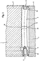
- Fig. 1 to 6 show a basic arrangement in plan view in an arrangement of the workpiece between the grinding wheel 1 and the regulating wheel 2 in a sectional course through the cutting planes 27 according to Fig. 7 ,
- Fig. 1 is disposed between the grinding wheel 1 and the regulating wheel 2, a shaft part 9, which has a curvature in exaggerated representation, so that in the central region of a maximum rounding error is present.
- Both the grinding wheel 1 and the regulating wheel 2 have at their lateral end portions profilings 3 and 4, which areas of larger diameter 5 of the grinding wheel 1 and larger diameter 6 of the regulating wheel 2 have.
- the diameters of the regions of increased diameter 5, 6 are dimensioned such that they are ground with them at the end regions of the shaft part 9, to which at the respective end faces centering 11 are introduced, before the grinding wheel 1 and the regulating wheel 2 in the region largest round impact of the shaft part 9 come into contact with this.
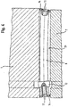
- a shaft part 9 to be ground is shown, which additionally has a collar, which is also used in this centerless grinding method is grinded from the outer diameter.
- a corresponding groove is provided in the grinding wheel 1 and also in the regulating wheel 2.
- the profiled areas 3, 4 of the grinding wheel 1 and the regulating wheel 2 according to the Fig. 2 to 6 are identical in dimensioning to the embodiment according to FIG Fig. 1 ,
- an additional profiling 30, which is a distance 13 for a support seat 15 to be ground (s.
- Fig. 3 trains.
- the distance 13 for the support seat is such that nevertheless first the end regions 28 of the shaft part 9 are ground by the profilings 3, 4 of the grinding wheel 1 and the regulating wheel 2, before the supporting seat 15 is ground by means of the profilings existing in the region of the greatest rounding error ,
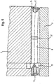
- Fig. 3 is the embodiment according to Fig. 2 shown, but the profiling 30 in the region of the largest round impact error of the shaft part on the grinding wheel 1 and the regulating wheel 2 have just come into engagement and the end portions 28 are at least partially ground on the shaft part 9 already.
- Fig. 4 shows a further embodiment according to the invention, in which the grinding wheel 1 and the regulating wheel 2 with respect to the dimensional and shape retention of the shaft part 9 have substantial areas of constant diameter. Both the grinding wheel 1 and the regulating wheel 2 thus have, except for the collar 12 on the shaft part 9 no profiling in their edge regions. Rather, the shaft part 9 is formed so that it has at its end regions in each case a collar, ie areas of larger diameter. According to Fig. 4 the workpiece 9 is also shown in an exaggerated manner with a curvature having a maximum rounding error approximately in its center. The grinding wheel 1 and the regulating wheel 2 are in the in Fig. 4 However, it is apparent that the intervention is imminent.
- the engagement initially takes place at the region of the collar, ie at the end regions of the shaft part 9, because there the distance between the grinding wheel 1 and the regulating wheel 2 is less than in the intermediate region, even in the region of the greatest rounding error of the shaft part 9.
- a further embodiment is shown, in which by the region of increased diameter, ie the collar 14 in the end region of the workpiece 9, a polished section, wherein as a situation just the engagement of grinding wheel 1 and regulating wheel 2 is shown.
- an area of increased diameter 31 on the shaft part ie a further collar is provided, which is suitable for grinding an additional support seat is provided.
- Such an additional support seat is useful above all when certain larger lengths of the workpiece, ie the shaft part are present.
- the area intended for the support seat is not ground yet. Only when a sufficiently strong bevel has taken place in the end regions of the shaft part 9, the grinding wheel 1 and the regulating wheel 2 will come into engagement with the central collar on the workpiece for grinding a support seat.
- Fig. 7 in side view, ie in a view in the direction of the longitudinal axes of the grinding wheel 1 and the regulating wheel 2, the arrangement of the distance between the grinding wheel and the regulating wheel including the arrangement of the shaft part 9 at this distance, that is shown in the grinding gap in conjunction with the support ruler 16.
- the wave-shaped part or the shaft part 9 is moved by engagement of the grinding wheel 1, which is driven in the direction of rotation 21, about its longitudinal axis 19 when resting on the support surface 24 of the support ruler 16 in the direction of rotation 23.
- the regulating wheel 2 is in its rotational direction 22 also in engagement with the shaft part 9 and thereby supports its rotation and forms together with the support surface 24 of the support ruler an abutment for introducing the grinding forces of the grinding wheel 1.
- the grinding wheel 1 rotates about its axis of rotation 17 and the regulating wheel 2 about its axis of rotation 18.
- the grinding wheel 1 is delivered in the feed direction 25, wherein the feed direction of the regulating wheel is characterized by the double arrow 26. Under delivery direction in each case a positive or negative feed direction is characterized, which is represented by the respective double arrows 25 and 26 respectively.
- the reference numeral 27, the cutting plane through the grinding wheel 1 and the regulating wheel 2 is shown, so that in the Fig. 1 to 6 shown distance refers to the related to the cutting planes 27 distance.
Landscapes
- Engineering & Computer Science (AREA)
- Mechanical Engineering (AREA)
- Grinding Of Cylindrical And Plane Surfaces (AREA)
- Grinding And Polishing Of Tertiary Curved Surfaces And Surfaces With Complex Shapes (AREA)
Claims (8)
- Procédé de dressage sans centre de pièces d'arbre (9), en particulier de tubes destinés à des arbres à cames incorporés, procédé dans lequel la pièce d'arbre (9) à dresser, comportant des centrages axiaux (11) au niveau de côtés frontaux, est dressée en étant entraînée en rotation à une distance (7, 8) entre le disque de dressage (1) et le disque de régulation (2), le disque de dressage (1) et le disque de régulation (2) ayant chacun une largeur qui correspond au moins à la longueur de la pièce d'arbre (9) et des coupes formées tout d'abord concentriquement aux centrages (11) étant réalisées au niveau de la pièce d'arbre (9) dans ses zones d'extrémité (28), après quoi la zone intermédiaire (29) située entre les zones d'extrémité (28) est dressée puis un dressage dimensionnel à conservation de forme de toute la pièce d'arbre (9) à la dimension finale est réalisé sur la base des coupes effectuées concentriquement aux centrages (11) et en appui sur une règle d'appui (16), au niveau des zones d'extrémité (28) de la pièce d'arbre (9).
- Procédé selon la revendication 1, dans lequel la pièce d'arbre (9) est dressée dans ses zones d'extrémité (28) par un disque de dressage (1) et un disque de régulation (2), chacun d'eux de plus grand diamètre, à une distance (7), formée dans les zones correspondant aux zones d'extrémité de la pièce d'arbre plus petites, entre le disque de dressage et le disque de réglage.
- Procédé selon la revendication 1, dans lequel la pièce d'arbre (9) comporte dans chacune de ses zones d'extrémité (28) une zone de plus grand diamètre ayant la forme d'une collerette (14) et le disque de dressage (1) et le disque de régulation (2) ont, dans leurs zones correspondant aux zones intermédiaires (29) de la pièce d'arbre (9), des diamètres tels que la collerette (14) de la pièce d'arbre (9) est tout d'abord dressée.
- Procédé selon la revendication 1 ou 2, dans lequel le disque de dressage (1) et le disque de régulation (2) comportent chacun, dans la zone intermédiaire (29) située entre les zones d'extrémité (28), en particulier au milieu, une zone de plus grand diamètre (30) au moyen de laquelle au moins un siège de support (15) concentrique aux centrages (11) est dressé au niveau de la pièce d'arbre (9).
- Procédé selon la revendication 4, dans lequel les zones d'extrémité (28) de la pièce d'arbre (9), puis l'au moins un siège de support (15) sont tout d'abord dressés après quoi la pièce d'arbre (9) est dressée dans toute sa longueur.
- Procédé selon la revendication 4, dans lequel les zones d'extrémité (28) et l'au moins un siège de support (15) sont dressés simultanément.
- Procédé selon la revendication 2, dans lequel la plus petite distance (7), prévue au niveau des zones d'extrémité (28) de la pièce d'arbre (9), a une valeur telle que, au niveau d'un plus grand débattement radial dans la zone située entre les zones d'extrémité (28), le dressage est commandé au plus tôt après avoir effectué la coupe des zones d'extrémité (28) de la pièce d'arbre (9).
- Procédé selon l'une des revendications 3 à 7, dans lequel la collerette (14), prévue au niveau des zones d'extrémité (28) de la pièce d'arbre (9), a un diamètre tel que, au niveau d'un plus grand débattement radial de la pièce d'arbre (9) dans la zone intermédiaire (29) située entre les zones d'extrémité (28), le dressage est commandé au plus tôt après avoir effectué la coupe des zones d'extrémité (28) de la pièce d'arbre (9).
Applications Claiming Priority (2)
| Application Number | Priority Date | Filing Date | Title |
|---|---|---|---|
| DE102013214226.9A DE102013214226B4 (de) | 2013-07-19 | 2013-07-19 | Verfahren zum centerless-schleifen von wellenteilen, insbesondere von rohren für gebaute nockenwellen, sowie dafür vorgesehenes schleifscheiben- und regelscheibenpaar |
| PCT/EP2014/062525 WO2015007444A1 (fr) | 2013-07-19 | 2014-06-16 | Procédé de rectification centerless de parties d'arbres, notamment de tubes pour arbres à cames assemblés, ainsi que paire constituée d'une meule de rectification et d'une meule de réglage prévue à cet effet |
Publications (2)
| Publication Number | Publication Date |
|---|---|
| EP3022014A1 EP3022014A1 (fr) | 2016-05-25 |
| EP3022014B1 true EP3022014B1 (fr) | 2019-10-23 |
Family
ID=50976627
Family Applications (1)
| Application Number | Title | Priority Date | Filing Date |
|---|---|---|---|
| EP14731228.4A Active EP3022014B1 (fr) | 2013-07-19 | 2014-06-16 | Procédé de rectification centerless de parties d'arbres, notamment de tubes pour arbres à cames assemblés |
Country Status (7)
| Country | Link |
|---|---|
| US (1) | US9878417B2 (fr) |
| EP (1) | EP3022014B1 (fr) |
| CN (1) | CN105392596B (fr) |
| DE (1) | DE102013214226B4 (fr) |
| ES (1) | ES2765207T3 (fr) |
| RU (1) | RU2660943C2 (fr) |
| WO (1) | WO2015007444A1 (fr) |
Families Citing this family (1)
| Publication number | Priority date | Publication date | Assignee | Title |
|---|---|---|---|---|
| DE102015206082A1 (de) | 2015-04-02 | 2016-10-06 | Mahle International Gmbh | Schleifmaschine |
Citations (1)
| Publication number | Priority date | Publication date | Assignee | Title |
|---|---|---|---|---|
| JP2004167610A (ja) * | 2002-11-18 | 2004-06-17 | Isobe Seiko Kk | 円柱状部品の多数個連続研削方法及び研削装置 |
Family Cites Families (18)
| Publication number | Priority date | Publication date | Assignee | Title |
|---|---|---|---|---|
| DD570A (fr) | ||||
| US1640993A (en) * | 1925-05-26 | 1927-08-30 | Einar A Hanson | Metal-working machine |
| US2280620A (en) * | 1939-02-28 | 1942-04-21 | Cincinnati Grinders Inc | Apparatus for finishing tubular articles |
| US2525591A (en) * | 1945-01-18 | 1950-10-10 | Louis M Cotchett | Top roll for textile drafting mechanisms |
| US3108411A (en) * | 1961-10-26 | 1963-10-29 | D Errico Pasquale | Attachment for centerless grinder |
| DE1293640B (de) * | 1964-11-27 | 1969-09-11 | Verfahren und Vorrichtung zum Schleifen von Zentrierkegeln. Anis: Aktietoolaget Malcus Holmquist, Halmstad (Schweden) | |
| US4009538A (en) * | 1975-01-08 | 1977-03-01 | John Hanecker | Fixture for converting a centerless grinder to a center grinder |
| DD119009A1 (fr) | 1975-04-29 | 1976-04-05 | ||
| JPS56157939A (en) * | 1980-05-12 | 1981-12-05 | Honda Motor Co Ltd | Crankshaft work processor |
| SU963814A1 (ru) * | 1981-03-31 | 1982-10-07 | Московский Автомобильный Завод Им.И.А.Лихачева (Производственное Объединение Зил) | Устройство дл бесцентрового шлифовани ступенчатых валов |
| JPS6025640A (ja) * | 1983-07-21 | 1985-02-08 | Toyoda Mach Works Ltd | 段付軸の成形加工方法 |
| JPH0413075Y2 (fr) * | 1987-11-18 | 1992-03-27 | ||
| JPH11322113A (ja) * | 1998-05-11 | 1999-11-24 | Suncall Corp | スキュー抑制型送給ロールとセンターレス研削装置 |
| JP2000263395A (ja) * | 1999-03-11 | 2000-09-26 | Noritake Diamond Ind Co Ltd | センタレス研削用ブレード |
| DE10308292B4 (de) * | 2003-02-26 | 2007-08-09 | Erwin Junker Maschinenfabrik Gmbh | Verfahren zum Rundschleifen bei der Herstellung von Werkzeugen aus Hartmetall und Rundschleifmaschine zum Schleifen von zylindrischen Ausgangskörpern bei der Herstellung von Werkzeugen aus Hartmetall |
| JP5173592B2 (ja) * | 2008-05-24 | 2013-04-03 | 光洋機械工業株式会社 | 円筒状工作物の曲り取り方法、センタレス研削方法および装置 |
| CN101704204A (zh) * | 2009-11-12 | 2010-05-12 | 杭州劳格罗拉轴承滚子有限公司 | 球面滚子无心贯穿式超精研方法 |
| DE102010010758B4 (de) | 2010-03-09 | 2014-03-06 | Erwin Junker Grinding Technology A.S. | Spitzenlose Rundschleifmaschine zum Schleifen von stangenförmigen Werkstücken und Verfahren zum spitzenlosen Rundschleifen von stangenförmigen Werkstücken |
-
2013
- 2013-07-19 DE DE102013214226.9A patent/DE102013214226B4/de active Active
-
2014
- 2014-06-16 RU RU2016102744A patent/RU2660943C2/ru active
- 2014-06-16 WO PCT/EP2014/062525 patent/WO2015007444A1/fr not_active Ceased
- 2014-06-16 US US14/903,202 patent/US9878417B2/en active Active
- 2014-06-16 ES ES14731228T patent/ES2765207T3/es active Active
- 2014-06-16 CN CN201480040728.5A patent/CN105392596B/zh active Active
- 2014-06-16 EP EP14731228.4A patent/EP3022014B1/fr active Active
Patent Citations (1)
| Publication number | Priority date | Publication date | Assignee | Title |
|---|---|---|---|---|
| JP2004167610A (ja) * | 2002-11-18 | 2004-06-17 | Isobe Seiko Kk | 円柱状部品の多数個連続研削方法及び研削装置 |
Also Published As
| Publication number | Publication date |
|---|---|
| RU2016102744A (ru) | 2017-08-01 |
| CN105392596A (zh) | 2016-03-09 |
| ES2765207T3 (es) | 2020-06-08 |
| WO2015007444A1 (fr) | 2015-01-22 |
| DE102013214226B4 (de) | 2018-06-21 |
| US9878417B2 (en) | 2018-01-30 |
| RU2016102744A3 (fr) | 2018-03-13 |
| EP3022014A1 (fr) | 2016-05-25 |
| CN105392596B (zh) | 2017-06-16 |
| DE102013214226A1 (de) | 2015-01-22 |
| RU2660943C2 (ru) | 2018-07-11 |
| US20160151875A1 (en) | 2016-06-02 |
Similar Documents
| Publication | Publication Date | Title |
|---|---|---|
| EP3274120B1 (fr) | Procédé et dispositif d'usinage de précision de pignons trempés et dentés | |
| EP2167277B1 (fr) | Centre de rectification et procédé de rectification simultanée de plusieurs paliers et de surfaces d'extrémité de vilebrequins | |
| DE10144649C5 (de) | Verfahren zur drallfreien spanenden Bearbeitung von rotationssymmetrischen Flächen | |
| EP2759364B1 (fr) | Outil de ponçage de pièces dentées dotées d'un contour de collision | |
| EP2167275B1 (fr) | Station de meulage et procede de meulage simultane de plusieurs paliers de vilebrequin | |
| DE10144644B4 (de) | Verfahren und Vorrichtung zum Schleifen von zentrischen Lagerstellen von Kurbelwellen | |
| DE102011113757B4 (de) | Verfahren und Vorrichtung zur Fertigbearbeitung von Werkstücken | |
| EP0497008B1 (fr) | Procédé et appareil pour la rectification de cames ou similaires | |
| DE19919893A1 (de) | Vor- und Fertigschleifen einer Kurbelwelle in einer Aufspannung | |
| DE10308292A1 (de) | Verfahren zum Rundschleifen bei der Herstellung von Werkzeugen aus Hartmetall und Rundschleifmaschine zum Schleifen von zylindrischen Ausgangskörpern bei der Herstellung von Werkzeugen aus Hartmetall | |
| DE102011113756A1 (de) | Verfahren und Vorrichtung zur Fertigbearbeitung von Werkstücken | |
| DE102011113758A1 (de) | Verfahren und Vorrichtung zur Fertigbearbeitung von Werkstücken | |
| EP2559518A2 (fr) | Meuleuse simultanée | |
| EP0542026B1 (fr) | Procédé d'usinage de surface à symétrie de rotation, en particulier vilebrequin, ainsi que outil pour la réalisation d'un tel procédé | |
| WO2017157698A1 (fr) | Procédé pour l'usinage complet par meulage de pièces ondulées présentant des parties cylindriques et profilées | |
| EP0518242B1 (fr) | Méthode et outil pour l'usinage de surfaces cylindriques à des pièces | |
| DE4202513C2 (de) | Verfahren zum Schleifen von Hublagerzapfen einer Kurbelwelle und Schleifmaschine zur Durchführung des Verfahrens | |
| DE4107462C2 (de) | Werkzeugmaschine zur spanabhebenden Bearbeitung von Werkstücken | |
| EP0211216B1 (fr) | Machine avec des outils de brochage rotatifs | |
| DE19918289A1 (de) | Verfahren zum Herstellen verzahnter Werkstücke | |
| EP3022014B1 (fr) | Procédé de rectification centerless de parties d'arbres, notamment de tubes pour arbres à cames assemblés | |
| DE10113301B4 (de) | Verfahren und Vorrichtung zum Hinterschleifen der Schneidzähne von zylindrisch oder kegelig geformten Abwalzfräsern sowie Abwalzfräser | |
| EP0274497B1 (fr) | Procede et dispositif de meulage sur mesure d'ebauches de pieces preformees | |
| EP0841116A2 (fr) | Méthode de travail de surfaces de pièces symétriques en rotation et outil employé | |
| DE102017217078A1 (de) | Kugelgewinde, Schleifscheibe und Verfahren zum Herstellen eines Kugelgewindes |
Legal Events
| Date | Code | Title | Description |
|---|---|---|---|
| PUAI | Public reference made under article 153(3) epc to a published international application that has entered the european phase |
Free format text: ORIGINAL CODE: 0009012 |
|
| 17P | Request for examination filed |
Effective date: 20160128 |
|
| AK | Designated contracting states |
Kind code of ref document: A1 Designated state(s): AL AT BE BG CH CY CZ DE DK EE ES FI FR GB GR HR HU IE IS IT LI LT LU LV MC MK MT NL NO PL PT RO RS SE SI SK SM TR |
|
| AX | Request for extension of the european patent |
Extension state: BA ME |
|
| DAX | Request for extension of the european patent (deleted) | ||
| GRAP | Despatch of communication of intention to grant a patent |
Free format text: ORIGINAL CODE: EPIDOSNIGR1 |
|
| STAA | Information on the status of an ep patent application or granted ep patent |
Free format text: STATUS: GRANT OF PATENT IS INTENDED |
|
| INTG | Intention to grant announced |
Effective date: 20190711 |
|
| GRAS | Grant fee paid |
Free format text: ORIGINAL CODE: EPIDOSNIGR3 |
|
| GRAA | (expected) grant |
Free format text: ORIGINAL CODE: 0009210 |
|
| STAA | Information on the status of an ep patent application or granted ep patent |
Free format text: STATUS: THE PATENT HAS BEEN GRANTED |
|
| AK | Designated contracting states |
Kind code of ref document: B1 Designated state(s): AL AT BE BG CH CY CZ DE DK EE ES FI FR GB GR HR HU IE IS IT LI LT LU LV MC MK MT NL NO PL PT RO RS SE SI SK SM TR |
|
| REG | Reference to a national code |
Ref country code: GB Ref legal event code: FG4D Free format text: NOT ENGLISH |
|
| REG | Reference to a national code |
Ref country code: CH Ref legal event code: EP |
|
| REG | Reference to a national code |
Ref country code: IE Ref legal event code: FG4D Free format text: LANGUAGE OF EP DOCUMENT: GERMAN |
|
| REG | Reference to a national code |
Ref country code: DE Ref legal event code: R096 Ref document number: 502014012906 Country of ref document: DE |
|
| REG | Reference to a national code |
Ref country code: AT Ref legal event code: REF Ref document number: 1193144 Country of ref document: AT Kind code of ref document: T Effective date: 20191115 |
|
| REG | Reference to a national code |
Ref country code: NL Ref legal event code: MP Effective date: 20191023 |
|
| REG | Reference to a national code |
Ref country code: LT Ref legal event code: MG4D |
|
| PG25 | Lapsed in a contracting state [announced via postgrant information from national office to epo] |
Ref country code: NL Free format text: LAPSE BECAUSE OF FAILURE TO SUBMIT A TRANSLATION OF THE DESCRIPTION OR TO PAY THE FEE WITHIN THE PRESCRIBED TIME-LIMIT Effective date: 20191023 Ref country code: LV Free format text: LAPSE BECAUSE OF FAILURE TO SUBMIT A TRANSLATION OF THE DESCRIPTION OR TO PAY THE FEE WITHIN THE PRESCRIBED TIME-LIMIT Effective date: 20191023 Ref country code: NO Free format text: LAPSE BECAUSE OF FAILURE TO SUBMIT A TRANSLATION OF THE DESCRIPTION OR TO PAY THE FEE WITHIN THE PRESCRIBED TIME-LIMIT Effective date: 20200123 Ref country code: SE Free format text: LAPSE BECAUSE OF FAILURE TO SUBMIT A TRANSLATION OF THE DESCRIPTION OR TO PAY THE FEE WITHIN THE PRESCRIBED TIME-LIMIT Effective date: 20191023 Ref country code: PL Free format text: LAPSE BECAUSE OF FAILURE TO SUBMIT A TRANSLATION OF THE DESCRIPTION OR TO PAY THE FEE WITHIN THE PRESCRIBED TIME-LIMIT Effective date: 20191023 Ref country code: PT Free format text: LAPSE BECAUSE OF FAILURE TO SUBMIT A TRANSLATION OF THE DESCRIPTION OR TO PAY THE FEE WITHIN THE PRESCRIBED TIME-LIMIT Effective date: 20200224 Ref country code: BG Free format text: LAPSE BECAUSE OF FAILURE TO SUBMIT A TRANSLATION OF THE DESCRIPTION OR TO PAY THE FEE WITHIN THE PRESCRIBED TIME-LIMIT Effective date: 20200123 Ref country code: LT Free format text: LAPSE BECAUSE OF FAILURE TO SUBMIT A TRANSLATION OF THE DESCRIPTION OR TO PAY THE FEE WITHIN THE PRESCRIBED TIME-LIMIT Effective date: 20191023 Ref country code: GR Free format text: LAPSE BECAUSE OF FAILURE TO SUBMIT A TRANSLATION OF THE DESCRIPTION OR TO PAY THE FEE WITHIN THE PRESCRIBED TIME-LIMIT Effective date: 20200124 Ref country code: FI Free format text: LAPSE BECAUSE OF FAILURE TO SUBMIT A TRANSLATION OF THE DESCRIPTION OR TO PAY THE FEE WITHIN THE PRESCRIBED TIME-LIMIT Effective date: 20191023 |
|
| PG25 | Lapsed in a contracting state [announced via postgrant information from national office to epo] |
Ref country code: IS Free format text: LAPSE BECAUSE OF FAILURE TO SUBMIT A TRANSLATION OF THE DESCRIPTION OR TO PAY THE FEE WITHIN THE PRESCRIBED TIME-LIMIT Effective date: 20200224 Ref country code: HR Free format text: LAPSE BECAUSE OF FAILURE TO SUBMIT A TRANSLATION OF THE DESCRIPTION OR TO PAY THE FEE WITHIN THE PRESCRIBED TIME-LIMIT Effective date: 20191023 Ref country code: RS Free format text: LAPSE BECAUSE OF FAILURE TO SUBMIT A TRANSLATION OF THE DESCRIPTION OR TO PAY THE FEE WITHIN THE PRESCRIBED TIME-LIMIT Effective date: 20191023 |
|
| REG | Reference to a national code |
Ref country code: ES Ref legal event code: FG2A Ref document number: 2765207 Country of ref document: ES Kind code of ref document: T3 Effective date: 20200608 |
|
| PG25 | Lapsed in a contracting state [announced via postgrant information from national office to epo] |
Ref country code: AL Free format text: LAPSE BECAUSE OF FAILURE TO SUBMIT A TRANSLATION OF THE DESCRIPTION OR TO PAY THE FEE WITHIN THE PRESCRIBED TIME-LIMIT Effective date: 20191023 |
|
| REG | Reference to a national code |
Ref country code: DE Ref legal event code: R097 Ref document number: 502014012906 Country of ref document: DE |
|
| PG2D | Information on lapse in contracting state deleted |
Ref country code: IS |
|
| PG25 | Lapsed in a contracting state [announced via postgrant information from national office to epo] |
Ref country code: IS Free format text: LAPSE BECAUSE OF FAILURE TO SUBMIT A TRANSLATION OF THE DESCRIPTION OR TO PAY THE FEE WITHIN THE PRESCRIBED TIME-LIMIT Effective date: 20200223 Ref country code: RO Free format text: LAPSE BECAUSE OF FAILURE TO SUBMIT A TRANSLATION OF THE DESCRIPTION OR TO PAY THE FEE WITHIN THE PRESCRIBED TIME-LIMIT Effective date: 20191023 Ref country code: DK Free format text: LAPSE BECAUSE OF FAILURE TO SUBMIT A TRANSLATION OF THE DESCRIPTION OR TO PAY THE FEE WITHIN THE PRESCRIBED TIME-LIMIT Effective date: 20191023 Ref country code: EE Free format text: LAPSE BECAUSE OF FAILURE TO SUBMIT A TRANSLATION OF THE DESCRIPTION OR TO PAY THE FEE WITHIN THE PRESCRIBED TIME-LIMIT Effective date: 20191023 |
|
| PLBE | No opposition filed within time limit |
Free format text: ORIGINAL CODE: 0009261 |
|
| STAA | Information on the status of an ep patent application or granted ep patent |
Free format text: STATUS: NO OPPOSITION FILED WITHIN TIME LIMIT |
|
| PG25 | Lapsed in a contracting state [announced via postgrant information from national office to epo] |
Ref country code: SK Free format text: LAPSE BECAUSE OF FAILURE TO SUBMIT A TRANSLATION OF THE DESCRIPTION OR TO PAY THE FEE WITHIN THE PRESCRIBED TIME-LIMIT Effective date: 20191023 Ref country code: SM Free format text: LAPSE BECAUSE OF FAILURE TO SUBMIT A TRANSLATION OF THE DESCRIPTION OR TO PAY THE FEE WITHIN THE PRESCRIBED TIME-LIMIT Effective date: 20191023 |
|
| 26N | No opposition filed |
Effective date: 20200724 |
|
| PG25 | Lapsed in a contracting state [announced via postgrant information from national office to epo] |
Ref country code: SI Free format text: LAPSE BECAUSE OF FAILURE TO SUBMIT A TRANSLATION OF THE DESCRIPTION OR TO PAY THE FEE WITHIN THE PRESCRIBED TIME-LIMIT Effective date: 20191023 |
|
| PG25 | Lapsed in a contracting state [announced via postgrant information from national office to epo] |
Ref country code: MC Free format text: LAPSE BECAUSE OF FAILURE TO SUBMIT A TRANSLATION OF THE DESCRIPTION OR TO PAY THE FEE WITHIN THE PRESCRIBED TIME-LIMIT Effective date: 20191023 |
|
| REG | Reference to a national code |
Ref country code: CH Ref legal event code: PL |
|
| GBPC | Gb: european patent ceased through non-payment of renewal fee |
Effective date: 20200616 |
|
| PG25 | Lapsed in a contracting state [announced via postgrant information from national office to epo] |
Ref country code: LU Free format text: LAPSE BECAUSE OF NON-PAYMENT OF DUE FEES Effective date: 20200616 |
|
| REG | Reference to a national code |
Ref country code: BE Ref legal event code: MM Effective date: 20200630 |
|
| PG25 | Lapsed in a contracting state [announced via postgrant information from national office to epo] |
Ref country code: LI Free format text: LAPSE BECAUSE OF NON-PAYMENT OF DUE FEES Effective date: 20200630 Ref country code: GB Free format text: LAPSE BECAUSE OF NON-PAYMENT OF DUE FEES Effective date: 20200616 Ref country code: IE Free format text: LAPSE BECAUSE OF NON-PAYMENT OF DUE FEES Effective date: 20200616 Ref country code: CH Free format text: LAPSE BECAUSE OF NON-PAYMENT OF DUE FEES Effective date: 20200630 Ref country code: FR Free format text: LAPSE BECAUSE OF NON-PAYMENT OF DUE FEES Effective date: 20200630 |
|
| PG25 | Lapsed in a contracting state [announced via postgrant information from national office to epo] |
Ref country code: BE Free format text: LAPSE BECAUSE OF NON-PAYMENT OF DUE FEES Effective date: 20200630 |
|
| REG | Reference to a national code |
Ref country code: AT Ref legal event code: MM01 Ref document number: 1193144 Country of ref document: AT Kind code of ref document: T Effective date: 20200616 |
|
| PG25 | Lapsed in a contracting state [announced via postgrant information from national office to epo] |
Ref country code: AT Free format text: LAPSE BECAUSE OF NON-PAYMENT OF DUE FEES Effective date: 20200616 |
|
| PG25 | Lapsed in a contracting state [announced via postgrant information from national office to epo] |
Ref country code: TR Free format text: LAPSE BECAUSE OF FAILURE TO SUBMIT A TRANSLATION OF THE DESCRIPTION OR TO PAY THE FEE WITHIN THE PRESCRIBED TIME-LIMIT Effective date: 20191023 Ref country code: MT Free format text: LAPSE BECAUSE OF FAILURE TO SUBMIT A TRANSLATION OF THE DESCRIPTION OR TO PAY THE FEE WITHIN THE PRESCRIBED TIME-LIMIT Effective date: 20191023 Ref country code: CY Free format text: LAPSE BECAUSE OF FAILURE TO SUBMIT A TRANSLATION OF THE DESCRIPTION OR TO PAY THE FEE WITHIN THE PRESCRIBED TIME-LIMIT Effective date: 20191023 |
|
| PG25 | Lapsed in a contracting state [announced via postgrant information from national office to epo] |
Ref country code: MK Free format text: LAPSE BECAUSE OF FAILURE TO SUBMIT A TRANSLATION OF THE DESCRIPTION OR TO PAY THE FEE WITHIN THE PRESCRIBED TIME-LIMIT Effective date: 20191023 |
|
| PGFP | Annual fee paid to national office [announced via postgrant information from national office to epo] |
Ref country code: CZ Payment date: 20250604 Year of fee payment: 12 |
|
| PGFP | Annual fee paid to national office [announced via postgrant information from national office to epo] |
Ref country code: ES Payment date: 20250701 Year of fee payment: 12 |
|
| PGFP | Annual fee paid to national office [announced via postgrant information from national office to epo] |
Ref country code: DE Payment date: 20250827 Year of fee payment: 12 |
|
| PGFP | Annual fee paid to national office [announced via postgrant information from national office to epo] |
Ref country code: IT Payment date: 20250627 Year of fee payment: 12 |