EP3022418B1 - Système perfectionné de soupape de dérivation turbocompressé ou suralimenté pour véhicule motorisé - Google Patents
Système perfectionné de soupape de dérivation turbocompressé ou suralimenté pour véhicule motorisé Download PDFInfo
- Publication number
- EP3022418B1 EP3022418B1 EP14825723.1A EP14825723A EP3022418B1 EP 3022418 B1 EP3022418 B1 EP 3022418B1 EP 14825723 A EP14825723 A EP 14825723A EP 3022418 B1 EP3022418 B1 EP 3022418B1
- Authority
- EP
- European Patent Office
- Prior art keywords
- valve
- valve member
- aperture
- piston
- pressure
- Prior art date
- Legal status (The legal status is an assumption and is not a legal conclusion. Google has not performed a legal analysis and makes no representation as to the accuracy of the status listed.)
- Active
Links
Images





Classifications
-
- F—MECHANICAL ENGINEERING; LIGHTING; HEATING; WEAPONS; BLASTING
- F02—COMBUSTION ENGINES; HOT-GAS OR COMBUSTION-PRODUCT ENGINE PLANTS
- F02B—INTERNAL-COMBUSTION PISTON ENGINES; COMBUSTION ENGINES IN GENERAL
- F02B37/00—Engines characterised by provision of pumps driven at least for part of the time by exhaust
- F02B37/12—Control of the pumps
- F02B37/16—Control of the pumps by bypassing charging air
-
- F—MECHANICAL ENGINEERING; LIGHTING; HEATING; WEAPONS; BLASTING
- F02—COMBUSTION ENGINES; HOT-GAS OR COMBUSTION-PRODUCT ENGINE PLANTS
- F02B—INTERNAL-COMBUSTION PISTON ENGINES; COMBUSTION ENGINES IN GENERAL
- F02B29/00—Engines characterised by provision for charging or scavenging not provided for in groups F02B25/00, F02B27/00 or F02B33/00 - F02B39/00; Details thereof
- F02B29/08—Modifying distribution valve timing for charging purposes
- F02B29/083—Cyclically operated valves disposed upstream of the cylinder intake valve, controlled by external means
-
- F—MECHANICAL ENGINEERING; LIGHTING; HEATING; WEAPONS; BLASTING
- F02—COMBUSTION ENGINES; HOT-GAS OR COMBUSTION-PRODUCT ENGINE PLANTS
- F02B—INTERNAL-COMBUSTION PISTON ENGINES; COMBUSTION ENGINES IN GENERAL
- F02B33/00—Engines characterised by provision of pumps for charging or scavenging
- F02B33/32—Engines with pumps other than of reciprocating-piston type
-
- F—MECHANICAL ENGINEERING; LIGHTING; HEATING; WEAPONS; BLASTING
- F02—COMBUSTION ENGINES; HOT-GAS OR COMBUSTION-PRODUCT ENGINE PLANTS
- F02B—INTERNAL-COMBUSTION PISTON ENGINES; COMBUSTION ENGINES IN GENERAL
- F02B33/00—Engines characterised by provision of pumps for charging or scavenging
- F02B33/44—Passages conducting the charge from the pump to the engine inlet, e.g. reservoirs
-
- F—MECHANICAL ENGINEERING; LIGHTING; HEATING; WEAPONS; BLASTING
- F16—ENGINEERING ELEMENTS AND UNITS; GENERAL MEASURES FOR PRODUCING AND MAINTAINING EFFECTIVE FUNCTIONING OF MACHINES OR INSTALLATIONS; THERMAL INSULATION IN GENERAL
- F16K—VALVES; TAPS; COCKS; ACTUATING-FLOATS; DEVICES FOR VENTING OR AERATING
- F16K1/00—Lift valves or globe valves, i.e. cut-off apparatus with closure members having at least a component of their opening and closing motion perpendicular to the closing faces
- F16K1/32—Details
- F16K1/34—Cutting-off parts, e.g. valve members, seats
- F16K1/36—Valve members
- F16K1/38—Valve members of conical shape
-
- F—MECHANICAL ENGINEERING; LIGHTING; HEATING; WEAPONS; BLASTING
- F16—ENGINEERING ELEMENTS AND UNITS; GENERAL MEASURES FOR PRODUCING AND MAINTAINING EFFECTIVE FUNCTIONING OF MACHINES OR INSTALLATIONS; THERMAL INSULATION IN GENERAL
- F16K—VALVES; TAPS; COCKS; ACTUATING-FLOATS; DEVICES FOR VENTING OR AERATING
- F16K3/00—Gate valves or sliding valves, i.e. cut-off apparatus with closing members having a sliding movement along the seat for opening and closing
- F16K3/02—Gate valves or sliding valves, i.e. cut-off apparatus with closing members having a sliding movement along the seat for opening and closing with flat sealing faces; Packings therefor
- F16K3/0218—Gate valves or sliding valves, i.e. cut-off apparatus with closing members having a sliding movement along the seat for opening and closing with flat sealing faces; Packings therefor with only one sealing face
-
- F—MECHANICAL ENGINEERING; LIGHTING; HEATING; WEAPONS; BLASTING
- F16—ENGINEERING ELEMENTS AND UNITS; GENERAL MEASURES FOR PRODUCING AND MAINTAINING EFFECTIVE FUNCTIONING OF MACHINES OR INSTALLATIONS; THERMAL INSULATION IN GENERAL
- F16K—VALVES; TAPS; COCKS; ACTUATING-FLOATS; DEVICES FOR VENTING OR AERATING
- F16K31/00—Actuating devices; Operating means; Releasing devices
- F16K31/12—Actuating devices; Operating means; Releasing devices actuated by fluid
- F16K31/36—Actuating devices; Operating means; Releasing devices actuated by fluid in which fluid from the circuit is constantly supplied to the fluid motor
- F16K31/38—Actuating devices; Operating means; Releasing devices actuated by fluid in which fluid from the circuit is constantly supplied to the fluid motor in which the fluid works directly on both sides of the fluid motor, one side being connected by means of a restricted passage and the motor being actuated by operating a discharge from that side
- F16K31/383—Actuating devices; Operating means; Releasing devices actuated by fluid in which fluid from the circuit is constantly supplied to the fluid motor in which the fluid works directly on both sides of the fluid motor, one side being connected by means of a restricted passage and the motor being actuated by operating a discharge from that side the fluid acting on a piston
-
- F—MECHANICAL ENGINEERING; LIGHTING; HEATING; WEAPONS; BLASTING
- F16—ENGINEERING ELEMENTS AND UNITS; GENERAL MEASURES FOR PRODUCING AND MAINTAINING EFFECTIVE FUNCTIONING OF MACHINES OR INSTALLATIONS; THERMAL INSULATION IN GENERAL
- F16K—VALVES; TAPS; COCKS; ACTUATING-FLOATS; DEVICES FOR VENTING OR AERATING
- F16K31/00—Actuating devices; Operating means; Releasing devices
- F16K31/12—Actuating devices; Operating means; Releasing devices actuated by fluid
- F16K31/36—Actuating devices; Operating means; Releasing devices actuated by fluid in which fluid from the circuit is constantly supplied to the fluid motor
- F16K31/40—Actuating devices; Operating means; Releasing devices actuated by fluid in which fluid from the circuit is constantly supplied to the fluid motor with electrically-actuated member in the discharge of the motor
-
- F—MECHANICAL ENGINEERING; LIGHTING; HEATING; WEAPONS; BLASTING
- F16—ENGINEERING ELEMENTS AND UNITS; GENERAL MEASURES FOR PRODUCING AND MAINTAINING EFFECTIVE FUNCTIONING OF MACHINES OR INSTALLATIONS; THERMAL INSULATION IN GENERAL
- F16K—VALVES; TAPS; COCKS; ACTUATING-FLOATS; DEVICES FOR VENTING OR AERATING
- F16K31/00—Actuating devices; Operating means; Releasing devices
- F16K31/12—Actuating devices; Operating means; Releasing devices actuated by fluid
- F16K31/36—Actuating devices; Operating means; Releasing devices actuated by fluid in which fluid from the circuit is constantly supplied to the fluid motor
- F16K31/40—Actuating devices; Operating means; Releasing devices actuated by fluid in which fluid from the circuit is constantly supplied to the fluid motor with electrically-actuated member in the discharge of the motor
- F16K31/406—Actuating devices; Operating means; Releasing devices actuated by fluid in which fluid from the circuit is constantly supplied to the fluid motor with electrically-actuated member in the discharge of the motor acting on a piston
-
- Y—GENERAL TAGGING OF NEW TECHNOLOGICAL DEVELOPMENTS; GENERAL TAGGING OF CROSS-SECTIONAL TECHNOLOGIES SPANNING OVER SEVERAL SECTIONS OF THE IPC; TECHNICAL SUBJECTS COVERED BY FORMER USPC CROSS-REFERENCE ART COLLECTIONS [XRACs] AND DIGESTS
- Y02—TECHNOLOGIES OR APPLICATIONS FOR MITIGATION OR ADAPTATION AGAINST CLIMATE CHANGE
- Y02T—CLIMATE CHANGE MITIGATION TECHNOLOGIES RELATED TO TRANSPORTATION
- Y02T10/00—Road transport of goods or passengers
- Y02T10/10—Internal combustion engine [ICE] based vehicles
- Y02T10/12—Improving ICE efficiencies
Definitions
- the present invention relates to diverter valve systems used with turbocharged or supercharged motor vehicles.
- turbocharged vehicle engines include some form of factory-fitted blow-off or bypass valve in the intake tract, the purpose of which is to open during throttle closure to provide a relief path from a diversion aperture for pressurised air that would otherwise cause significant pressure spikes, resulting in damage or reduced life-span of the turbocharger, and also an unpleasant fluttering noise that is deemed unacceptable in a road-going passenger car.
- Newer implementations include a mounting flange built directly into the turbo's compressor cover, which includes separate paths for both the incoming pressure and the vented air to be recirculated in the one flange.
- the factory bypass valve can be fitted to this type of flange, and is a direct-actuated solenoid type, that is controlled by a signal from the car's Engine Control Unit (ECU).
- This type of valve features an electric solenoid coil which has a plunger, on which plunger is mounted a valve member to open or close the diversion aperture in the intake tract.
- the plunger and valve member is biased to the closed position by a spring.
- the solenoid When the solenoid is energised, this pulls the plunger into the solenoid coil against the bias of the spring, and the valve member will thus open the diversion aperture.
- the plunger and the valve member are returned by the spring to the closed condition. In this system the plunger is connected directly to valve member that opens and closes the diversion aperture and thus bypass path.
- the OEM system operates as follows: the ECU monitors the accelerator pedal position, and if a rapid reduction in accelerator pedal position is detected, the ECU energises the solenoid coil to open the valve member and thus the bypass path.
- the ECU typically holds the bypass valve open for approximately 2 seconds, unless it detects that the accelerator pedal position is increased, at which point it will immediately de-energise the solenoid coil and thus close the diversion aperture and the bypass path.
- the first type uses a diaphragm and poppet-style valve that is connected to the solenoid plunger.
- There are holes in the face of the piston that transfer pressure to the back of the diaphragm in order to balance the opposing forces that result from the pressure acting on the areas in front of and behind the diaphragm, so that the sum of the forces is theoretically zero.
- the solenoid coil is able to pull the plunger, diaphragm and poppet valve open against the return spring, thereby opening up diversion aperture and the bypass path.
- the return spring returns the plunger, diaphragm and poppet valve to the closed position.
- the second type uses a plastic piston type valve that is connected to the solenoid plunger. Again, there are holes located in the face of the piston to equalise pressure front and back, thereby theoretically creating no resultant force. It operates in the same way as the diaphragm type described above.
- the third type is the same as the second type, except it features a slotted "basket” that shrouds the piston. Its purpose can only be assumed to aid closure when the piston is open and the solenoid is then de-energised.
- the third type is a further evolution of the second type, with the vented "basket” a clear attempt to diffuse the bypass air to reduce its velocity so it can enter the transfer holes in the face of the piston in order to balance the forces and allow it to close.
- this solution is only moderately effective, and certain conditions can still cause this valve type to be held open.
- After Market Valves there are two common approaches taken by aftermarket bypass valve manufacturers to solve the problems of the factory-fitted bypass valves. Both methods involve replacing the entire factory-fitted solenoid coil and valve entirely with a pneumatically-operated valve. Where the two methods differ however is how the pneumatic valves are controlled.
- One method supplies a 3-port solenoid valve that alternately connects a vacuum source and a pressure source to the pneumatic bypass valve - vacuum causes the bypass valve to open, pressure makes it close.
- the 3-port solenoid valve supplied with this kit connects to the factory wiring harness in the engine bay so it utilises the same signal from the ECU to determine when to open the bypass valve.
- the second method does not use the ECU signal at all. Instead, it simply connects the bypass valve directly to the intake manifold, thereby causing the valve to open when the throttle is closed and the intake manifold is in vacuum, and when the throttle is open the intake manifold is pressurised and therefore the bypass valve is closed. This is the common method used by most after-market bypass valves.
- the first method retains the ECU control, which is desirable for rapid response of the bypass valve opening, however to achieve this, the apparatus supplied in order to carry out this method is extensive, expensive, and time-consuming to install.
- the apparatus required to carry out the first method must include: a means to provide a hose connection to the intake manifold; a 3-port solenoid valve; a means of electrically connecting the 3 port solenoid valve to the factory wiring harness; a mounting bracket to hold the 3 port solenoid valve in place; sufficient lengths of vacuum hose to connect the 3 port solenoid valve; and a pneumatically-operated bypass valve. Installation of this apparatus requires significant time, typically at least an hour by an experienced vehicle mechanic.
- the second method suffers similar deficiencies.
- the apparatus required to carry out the second method must include: a means to provide a hose connection to the intake manifold; a means to provide an electrical ballast load to the factory wiring harness to prevent the ECU from detecting a bypass valve fault since the factory-fitted solenoid coil has been removed; sufficient lengths of vacuum hose to connect the intake manifold valve to the bypass valve; a pneumatically-operated bypass valve.
- installation of this apparatus requires significant time, typically at least an hour by an experienced vehicle mechanic.
- This method also suffers from delayed opening time for the same reason as the first method - the apparatus requires the intake manifold to achieve sufficient vacuum to aid bypass valve opening, by which time a pressure spike has already occurred.
- US8191855 discloses a bypass valve for internal combustion engines for connecting the pressure side to the intake side of a supercharging device.
- the bypass valve includes an electromagnetic actuator and a valve housing in which a closing component is movably accommodated.
- the closing component has a valve body, acted upon by pressure and movable in a flow channel, and a switchable sealing element.
- the present invention provides a turbo or supercharged intake tract diverter valve system according to claim 1.
- the valve member can be a generally hollow piston with said transfer aperture being through an otherwise closed off end or face of said piston.
- the chamber can be formed from side walls attached to said valve body, and said piston, with said chamber being optionally of a generally cylindrical construction.
- the ratio of cross sectional area of said transfer aperture with respect to the cross sectional area of said control aperture is less than or equal to 1:2; or the cross sectional area of the control aperture is at least twice the magnitude of the cross sectional area of the transfer aperture in the valve member.
- the surface area of said valve member on the upstream side, which is directly exposed to said pressurised gas, is less than the surface area of said valve member on the downstream side which is exposed to said pressurised gas via said transfer aperture.
- the surface area on the downstream side of said valve member from said transfer aperture can be one or more of the following: at least 10% greater than that of the upstream side; at least 20% greater than that of the upstream side; at least 30% greater than that of the upstream side.
- the actuation means is one or more than one of the following: activated by a vehicle's engine control unit or ECU; includes a solenoid, or a control valve member cooperating with a solenoid, to open or close said control aperture: located in said valve body adjacent said valve member: is located in a body remotely located from said body having said valve member: is located in a body remotely located from said body having said valve member and said body having said valve member between respective ports interconnection by means of flexible tubing.
- a return spring can be provided between one end of said chamber and said valve member, so that said valve member when in a closed condition has one of the following: no pre-load force from the return spring; the pre-load force is in the range of greater than zero and up to 0.2kg.
- the spring provides one or more of the following: a pre-load force greater than zero, to urge the valve member to close said diversion aperture at an appropriate pressure differential; provides said valve member with a stroke length dependent upon the amount of pressure located in said intake tract.
- the diversion aperture can remain fully closed if the pressure in said tract is not sufficient to open said valve member against said return spring, even if the vehicle's engine control unit is energising the actuation means.
- valve is provided and or constructed as an OEM component or assembly: said valve is provided or constructed as an after-market component or assembly: said valve is constructed from a kit of parts, which utilises a vehicle's original factory fitted solenoid coil, and valve mounting flange; the vehicle's original factory fitted solenoid return spring is utilisated.
- the diverter valve system as described above can be provided or constructed as an after-market component or assembly, in which case the valve can be constructed from a kit of parts, which utilises a vehicle's original factory fitted solenoid coil, and valve mounting flange. Further, the vehicle's original factory fitted solenoid return spring can also be utilised or as is most preferred a stiffer spring than the factory one can be provided.
- the actuation means can be located in the valve body adjacent the valve member or the actuation means can be located in a body remotely located from said body having said valve member; in which case between said body remotely located from said body having said valve member and said body having said valve member the respective ports are interconnected by means of flexible tubing.
- the present invention also provides a method of operating a turbo or super charged intake tract diverter valve system, said method comprising the steps of providing a piston to open and close a diversion aperture of a bypass path, said piston having a transfer aperture through it, and an upstream surface area adapted to be in contact with a pressurised gas on an upstream side of said diversion aperture, which upstream surface area is less than a downstream surface area which will act under pressure of gas passing through said transfer aperture, providing a chamber to cooperate with said piston which has a control aperture therein, said method including the step of closing or opening said control aperture by means of an actuatable valve member, to allow said piston to open or close said diversion aperture.
- a return spring can be provided between a portion of said chamber and said piston so that said piston will have its stroke length dependent upon the amount of pressure located in said intake tract.
- the diversion aperture can remain fully closed when the pressure is not sufficient to open when the vehicle's engine control unit is energising the solenoid.
- the present invention further provides an automobile engine having a turbo or super charged intake tract diverter valve system pursuant to the invention.
- the present invention also provides an automobile having an automobile engine pursuant to the invention.
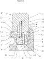
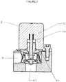
- the diverter valve system comprises a valve body 1 whose outer profile conforms to that of a vehicle's factory fitted solenoid coil body 2 and that of the mounting flange 3 which may be on the turbocharger compressor or other component of the engines intake tract, so that the valve body 1 is sandwiched between body 2 and flange 3.
- the valve body 1 contains a cylindrical wall 4 that is part of a bypass path 9 that leads back to the turbocharger compressor inlet.
- the wall 4 includes a chamber 5.1 which is formed by upper cylindrical wall 5.2 of cylindrical wall 4 and which is closed off by a wall 5 at the end within the valve body 1.
- the wall 5 contains a control aperture or hole 6, that allows the passage of air through it into a chamber 7 on the other side of the wall 5, and is bounded by the face of the solenoid coil body 2 when assembled.
- At least one transfer passage or passages 8 are included in the valve body 1 so as to allow passage of air from the chamber 7 to the outside of the valve body 1, via the recirculation passage or bypass path 9 when the valve is installed on a vehicle.
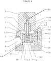
- the cylindrical wall 4 is formed in a frusto-conical formation 1.6, and that the lowermost rim 1.5 of this formation 1.6, is located at a distance (see arrow 4.2 in figure 4 ) of approximately 5mm. This distance is the same distance measurement which the piston valve of figure 7 will open to. Further this distance of 5mm will produce an opening to allow air for the diversion aperture 4.1 to directly flow through into the path 9, such that diversion aperture 4.1 and the passage past the rim 1.5 are of similar cross-sectional areas, thereby preventing the rim from obstructing flow into the bypass passage 9.
- the four transfer passages 8 are angularly equi-spaced around the circumference of the frusto-conical portion 1.6, with centres located on a concentric pitch circle diameter, and thus radially outwardly of the cylindrical wall 4, which produces an elliptical exit port from each of the passages 8.
- Four transfer passages are used in the embodiment of Figures 8 and 8A because of the thickness of the wall though which the transfer passages pass, and other manufacturing reasons. However, it will be understood that the number of transfer passages is not critical as long as the flow through the transfer passage or passages does not impede the flow of air from the control aperture, as described in paragraph [081] below.
- a cylindrical piston 10 illustrated in detail in Figure 10 , is formed by a hollow cylinder with a substantially closed-off end 10.1.
- the piston 10 is configured to fit inside the chamber 5.1 with a fit as close a practical to allow free axial movement, typically 0.015mm-0.05mm clearance.
- the closed-off end 10.1 further comprises a face seal 11 which will preferably include a circumferentially arranged bonded silicone bead, for sealing against the floor of the recirculation passage or bypass path 9 when installed, so as to close off the diversion aperture 4.1 at the start of the bypass path when the piston 10 is in the closed position.
- the closed-off end 10.1 further comprises a transfer or balance aperture 12 that allows passage of air from the upstream side of the piston face (that is on the diversion aperture 4.1 side) to the downstream side which is on the inside of the piston 10.
- the cross-sectional area of this transfer or balance aperture 12 will need to be at least 2 times smaller than the control aperture or hole 6 in the wall 5 of the valve body bore.
- the surface area of the face 10.2 of the piston closed off end 10.1 should be at least approximately 22% smaller in magnitude than the overall surface area calculated based on the outside diameter of the piston 10 (i.e. piston OD:face seal area is 1:0.78). In terms of ratio of diameters this equates to the diameter of the surface which closes the diversion aperture, is about 0.885 the size of the outside diameter of the piston 10.
- the effective area of the piston 10 on which the pressure acts on the back or downstream side is approximately 27% larger than the effective area of the piston on the upstream side defined by the bonded silicone face seal 11.1 that closes the diversion aperture 4.1, (that is the ratio of face seal surface area to OD surface area is 1:1.27).
- This surface area differential with respect to opposite sides (namely the upstream and downstream sides) of the piston 10 will ensure that the piston 10 closes the diversion aperture 4. 1 or keeps it closed, when gas pressure on opposite sides of the piston 10 is equal.
- a steel solenoid plunger 13 is designed, sized and shaped so as to fit onto the spigot 14 of the factory-fitted solenoid coil 2 when assembled, with provision for the factory return spring 15.
- the plunger 13 further comprises a face seal or O-ring 16 that ensures the control aperture or hole 6 in the wall 5 of the valve body 1 is closed off and sealed when the plunger 13 is in the closed position when the factory-fitted solenoid coil 2 is de-energised.
- An O-ring 17 is provided so as to cushion the retraction travel of the plunger 13 when the solenoid coil is energised, in order to prevent an audible "clack" sound which would otherwise be heard.
- a main return compression spring 18 of suitable dimensions and specification is provided so as to produce additional bias or returning force to the piston 10. It is preferred that the return spring provides no pre-load when the piston 10 is in the closed position, or if a preload is provided it is greater than zero but up to and preferably not exceeding 0.2kg of pre-load when the piston 10 is in the closed position, such as for the vehicles mentioned below. Pre-load is nil or if present is kept in the narrow range described so as to prevent or minimise the occurrence of turbo compressor surge.
- the spring rate should be such that the spring force is between 1-1.5kg at maximum piston lift for such vehicles. However, for other vehicular engines these spring parameters may vary in accordance with the pressures in the system and other factors like the turbo specification.
- the exact spring force and rate (which is a function of spring dimensions) may need to be determined by trial and error to determine a maximum pre-load on the piston 10 prior to the onset of compressor surge. It is believed that no more than 0.2kg of preload will prevent or minimise such compressor surge.
- the compression return spring 18 can be given no pre-load in the valve system assembly by either the piston 10 being sized such that the dimensions of the chamber 5.1, or the non compressed height of the spring is sized, so that when piston and spring is assembled, and the piston 10 has closed off the diversion aperture 4.1, the return spring 18 is in an uncompressed state.
- Another way to ensure that no preload is provided by the return spring 18, is to have the uncompressed height of the spring 18 less than the height of the chamber 5.1 when the piston 10 is in the closed off position relative to the diversion aperture 4.1. This will ensure that for the last part of the stroke of the piston 10 to the closed position that the piston 10 is not under the urging of the return spring 18.
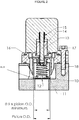
- the valve of Figures 1 and 2 can be constructed on an existing vehicle by removing some of the components of the original diverter valve, and by utilising the original factory-fitted solenoid coil 2.
- the factory-fitted valve mechanism once removed from the solenoid coil can be discarded.
- the factory-fitted solenoid return spring 15, and the mounting flange 3 which may be integrated into the turbocharger compressor cover, or may be remotely mounted and connected to the intake system via hoses, depending upon what is present on the original vehicle.
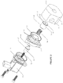
- the components described above are then assembled onto the mounting flange as illustrated in the exploded view of Figure 3 .
- the effective area of the piston 10 on which the pressure acts on the back or downstream side is approximately of preferably 27% (face seal surface area:OD surface area is 1:1.27) larger than the effective area of the piston on the upstream side, defined by the bonded silicone face seal 11.1 that closes the diversion aperture 4.1, there is an imbalanced or net force that pushes the piston 10 to close against the upper rim of the diversion aperture 4.1 on the mounting flange 3. Regardless of how high the boost pressure is or may be, the piston 10, due to this arrangement, will always be pushed closed by a force which is 27% greater than the force it would otherwise be pushed open with.
- the transfer aperture 12 in the closed end 10.1 of the piston 10 is smaller than the control aperture or hole 6 in the valve body wall 5 and the transfer passages 8, the pressure within the chamber 5.1 defined by the piston 10 and valve body or walls 5.2 will be sufficiently reduced to allow the imbalance of forces, or net force, to push the piston 10 open.
- recirculation of the pressurised air by means of the bypass path 9 can take place to prevent pressure spikes in the intake tract.
- the plunger 13 moves back under the bias of the spring 15 so as to close the control aperture 6 and once again seals the valve body chamber 5.1, allowing pressure to equalise on both sides of the piston 10. With equal pressure but un-equal areas exposed to the pressure, the piston 10 is then forced closed again.
- the valve utilises a return spring 18.
- a return spring 18 As illustrated in Figures 5 and 6 , there is another configuration of the apparatus that achieve different but desirable performance objectives.
- the valve When configured or assembled without the main return spring 18 as illustrated in Figures 5 and 6 , the valve most closely replicates the behaviour of the factory-fitted bypass valve, in that it operates only in two states, either open as in Figure 6 or closed Figure 5 . This configuration ensures the quietest possible operation, but still with the ability to open and close reliably even under higher boost pressure and temperature.
- the main return spring 18 influences the size of the opening created by the piston 10 in response to the boost pressure present in the intake tract and communicated by the diversion aperture 4.1. If boost pressure is low, the piston 10 only opens a small amount of bypass opening, with the key objective being to vent only enough air to prevent pressure spikes. As the boost pressure is reduced by the action of bypassing, the piston 10 closes the diversion aperture 4.1 or decreases the size of the bypass opening, until there is no more pressure and the piston 10 fully closes the diversion aperture 4.1, even when the ECU is energising the solenoid coil 2.
- boost pressure is high when the ECU energises the solenoid coil 2, the piston 10 will open further than when the pressure is lower, to allow more air to recirculate.
- the size of the bypass passage or opening can be described as variable or dependent upon the amount of boost pressure to be diverted, unlike some of the prior art systems where the amount of opening of the valve is the same at all pressures due to the length of stroke of the direct acting solenoid.
- the piston 10 is given a second means or parameter by which its opening stroke length is controlled.
- turbo lag By opening only enough to prevent pressure spikes when the throttle is closed, but not completely evacuating the intake tract, turbo lag can be minimised.
- the embodiment of Figures 1 to 4 may be preferable when better performance is required, but with it may come a slight increase in operational noise.
- diverter valve of the invention can be provided as an OEM diverter valve instead of the existing OEM diverter or bypass valves.
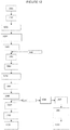
- Figure 12 illustrates a block diagram of the method of operation of the valve system of Figures 1 to 6 and 11 which will be described below.
- the items numbers represent the following block diagram steps:
- the piston transfer aperture 12 has a diameter of approximately 2mm, while the control aperture 6 has diameter of approximately 5mm, and there are four transfer passages 8 each of approximately 3mm in diameter.
- the cross-sectional area of the four transfer passages 8 is greater than that of the control aperture 6, thereby ensuring they create no additional downstream flow restriction or back pressure due to turbulence and/or the length of the transfer passages 8. Because the piston transfer aperture 12 is concentric to the control aperture 6, air passing through the piston transfer aperture 12 creates a jet that is directed into the control aperture 6, which entrains air from the surrounding chamber 5.1 which results in a slight vacuum in the chamber 5.1, thereby aiding the piston 10 moving to the open condition.
- the plunger 13 forms part of the path that air must take to evacuate the piston chamber 5.1, and therefore the retract distance of the plunger 13 also plays a role in determining the total flow capacity of the control aperture 6.
- the plunger 13 must retract sufficiently so as not to restrict flow through the control aperture 6. A preferred retract distance of 1mm to 2mm will satisfy this.
- the surface area that pressure gets to act upon on the upstream face of the piston is dictated by the diameter of the raised bead 11.1 of the moulded face seal 11.
- the raised bead 11.1 contacts the floor 9.1 (see figure 1 ) of the bypass path 9 which surrounds the upper rim of the diversion aperture 4.1, so the pressure only acts on the area enclosed by the bead 11.1.
- pressure on both sides (upstream and downstream of transfer aperture 12) of the piston is equalised, but on the back of the piston 10 the pressure acts on the entire area of the piston outer diameter, which therefore creates a resultant force pushing the piston 10 closed.
- the preferred bead diameter of 19.5mm can be utilised, while a piston outside diameter of 22mm is also utilised, resulting in a face surface area (upstream) to piston surface area (downstream) ratio of 1:1.27, when calculated with the surface area of the transfer aperture 12 removed from the available surface areas.
- a bead diameter of 21.5mm can be utilised with a piston outside diameter of 24mm, however, this will result in a face surface area (upstream) to piston surface area (downstream) ratio of 1:1.247, when calculated with the surface area of the transfer aperture 12 is removed from the available surface areas.
- Another parameter to be designed for is the speed at which the piston 10, will move from a closed to an open position. It is found that the parameters selected above will produce an appropriate speed of the piston 10 for effective opening of the diverter passage as a replacement for a factory solenoid diverter valve such as that manufactured by Pierburg for Volkswagen/Audi, where the valve of figure 7 has part number of 06F 145 710 G - commonly referred to by the Audi/VW community as the "Revision G" model. This valve is used on some Golf GTI, as well as other Audi/VW/Seat/Skoda models that share the same engine. BMW, Porsche, Peugeot and Mercedes also use a similar valve made by the same company.
- the standard direct actuating solenoid valve has a mounting flange 3, and in this is located the valve piston which is pushed shut by the return spring 15 of the solenoid.
- solenoid is energised by the ECU the direct coupled actuator rod opens the diversion path.
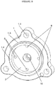
- FIGS 8 and 9 Illustrated in Figures 8 and 9 are perspective views of the valve body 1 of previous Figures, showing three mounting holes 1.1, which pass through the valve body, while on a lower face a circular O-ring channel 1.2 is provided so as to receive an O-ring to seal with the upper surface of the mounting flange 3.
- Figure 9 there is visible in the upper side the chamber 7 and the entrance location or apertures of the four transfer passages 8.
- a circular flange 1.3 to substitute for the material of the inserted chamber 9.3 of the factory valve of figure 7
- a cylindrical flange 1.4 to provide the cylindrical wall of the chamber 7.
- the valve body 1 can be manufactured from any appropriate material and any appropriate method of manufacture. While most preferred is machining the valve body 1 from aluminium, or other metals such as brass or stainless steel could be used or plastic; or it could be injection moulded in polymeric material, die cast or made from sintered metals. Metal deposition techniques could also be used and possibly 3D printing depending upon available polymers for such printing.
- the piston 10 can be made from any appropriate material including aluminium, stainless steel or appropriate polymeric materials or metals.
- Diverter valves as described above are commonly found in one of two locations, one is on a mounting flange that forms part of a supercharger or turbo compressor cover and includes a passage for incoming boost pressure, and one for the recirculation path.
- a second location used is a cast or machined mounting flange with the same inlet and outlet features but connected remotely to the intake via hoses.
- FIGURE 11 Illustrated in FIGURE 11 is another embodiment where the diverter valve system has a has two discrete body parts, so as to allow the location of the "upper" or first or actuator body part at one location in an engine bay and the "lower” or second or valve body part to be located on the turbocharger compressor or other component of the engine's intake tract at a second location in an engine bay.
- Like parts with the embodiment of Figures 1 to 6 have been like numbered.
- This embodiment of Figure 11 is particularly advantageous in instances where the engine bay is organised such that there is not much space above the turbocharger compressor or other component of the engine's intake tract on which the diverter valve may be mounted.
- the aperture 6 is effectively parted so that the aperture 6 is on the remote upper or first or actuator body 1.2, which connects to the port 6.1 on the lower or second or valve body 1, by means of tube 6.2.
- a single transfer passage 8 is split so that the lower or second or valve body 1 has a passage end 8.3 at the turbocharger compressor or other component of the engine's intake tract, while the remotely located body 1.2 has the other passage end 8.1 of the transfer passage 8, with ends 8.3 and 8.1 being connected by tube 8.2.
- the tubes 6.2 and 8.2 are a silicone rubber tubing which are capable of withstanding the boost pressure which may be present in the turbocharger system.
- Typical silicone vacuum hoses used for such purposes can readily withstand over 50 psi, but a hose's characteristics can be selected depending upon the conditions prevalent in a turbo charging system to which the embodiment is to be applied.
- a single transfer passage 8 is provided so as to minimise the number of tubes 8.2 that need to be connected, thus also minimising install time, length of tubing required and any additional clutter around the diverter valve system components.
Landscapes
- Engineering & Computer Science (AREA)
- General Engineering & Computer Science (AREA)
- Mechanical Engineering (AREA)
- Chemical & Material Sciences (AREA)
- Combustion & Propulsion (AREA)
- Magnetically Actuated Valves (AREA)
Claims (10)
- Système perfectionné de soupape de dérivation de voie d'admission turbocompressé ou suralimenté ayant un corps de soupape (1) pouvant s'adapter pour être monté de manière étanche sur ladite voie d'admission en amont d'un papillon des gaz associé à ladite voie d'admission, ledit corps (1) ayant des ouvertures de montage (1.1) à travers ce dernier, et comprenant un moyen de fermeture pour fermer, de manière opérationnelle, une ouverture de dérivation (4.1) dans ladite voie d'admission afin d'évacuer les gaz sous pression dans ladite voie d'admission vers une trajectoire de dérivation (9) ou l'atmosphère à des moments prédéterminés, ledit système comprenant un moyen d'actionnement pour permettre audit moyen de fermeture de s'ouvrir, moyennant quoi les gaz sous pression dans ladite voie d'admission passent à travers ladite ouverture de dérivation (4.1) dans ladite trajectoire de dérivation (9) ou l'atmosphère, ledit moyen de fermeture comprenant une chambre (5.1) associée audit corps de soupape (1) et un élément de soupape (10) qui coopère avec ladite chambre (5.1) pour fermer ladite ouverture de dérivation (4.1), ledit élément de soupape (10) comprenant au moins une ouverture de transfert (12) à travers ce dernier, ledit élément de soupape (10) est configuré de sorte qu'au moyen desdits gaz sous pression, ledit élément de soupape (10) a une force nette fournie à partir d'un différentiel de surface par rapport aux côtés en amont et en aval opposés dudit élément de soupape (10) afin de fermer ladite ouverture de dérivation (4.1) ou la maintenir fermée, lorsque la pression de gaz sur les côtés opposés dudit élément de soupape (10) est égale, et lorsqu'un différentiel de pression est créé de sorte qu'un côté en amont dudit élément de soupape (10) a une pression supérieure à un côté en aval, alors ledit élément de soupape (10) se déplace pour ouvrir ladite ouverture de dérivation (4.1), ledit système comprenant ledit moyen d'actionnement associé avec ladite chambre (5.1) ou ledit élément de soupape (10), ledit moyen d'actionnement ouvre une ouverture de commande (6) associée avec ladite chambre (1) pour créer ainsi ledit différentiel de pression sur l'élément de soupape (10) pour amener ainsi ce dernier à ouvrir ladite ouverture de dérivation (4.1), caractérisé en ce que ledit corps (1) a une partie tronconique (1.6), ladite chambre (5.1) étant généralement cylindrique et étant formée dans ladite partie tronconique (1.6), ledit corps de soupape (1) comprenant au moins un passage de transfert (8) à travers le corps (1) qui a un orifice formé dans la partie tronconique (1.6) au niveau d'une extrémité du au moins un passage (8).
- Système de soupape de dérivation selon la revendication 1, dans lequel ledit élément de soupape (10) est un piston généralement creux avec ladite ouverture de transfert (12) qui traverse une extrémité autrement fermée ou la face dudit piston.
- Système de soupape de dérivation selon l'une quelconque des revendications 1 ou 2, dans lequel le rapport de la surface transversale de ladite ouverture de transfert (12) par rapport à la surface transversale de ladite ouverture de commande (6) est inférieur ou égal à 1 :2 ou la surface transversale de l'ouverture de commande (6) représente au moins deux fois la grandeur de la surface transversale de l'ouverture de transfert (12) dans l'élément de soupape (1).
- Système de soupape de dérivation selon l'une quelconque des revendications 1 à 3, dans lequel la surface dudit élément de soupape (10) du côté en amont, qui est directement exposée audit gaz sous pression, est inférieure à la surface dudit élément de soupape (10) du côté en aval qui est exposée audit gaz sous pression via ladite ouverture de transfert (12).
- Système de soupape de dérivation selon la revendication 4, dans lequel ladite surface du côté en aval dudit élément de soupape (10) par rapport à ladite ouverture de transfert (12) correspond à une ou plusieurs propositions suivantes : au moins 10% plus grande que celle du côté en amont ; au moins 20% plus grande que celle du côté en amont ; au moins 30% plus grande que celle du côté en amont.
- Système de soupape de dérivation selon l'une quelconque des revendications précédentes, dans lequel ledit moyen d'actionnement comprend une ou plusieurs des propositions suivantes : actionné par une unité de commande de moteur ou ECU du véhicule ; comprend un solénoïde (2) ou un élément de soupape de commande (10) coopérant avec un solénoïde (2) pour ouvrir ou fermer ladite ouverture de commande ; positionné dans ledit corps de soupape (1) adjacent audit élément de soupape (10) ; est positionné dans un corps situé à distance dudit corps (1) ayant ledit élément de soupape ; est positionné dans un corps situé à distance dudit corps (1) ayant ledit élément de soupape (10) et ledit corps (1) ayant ledit élément de soupape (10), ont, entre des orifices respectifs, une interconnexion au moyen d'un tubage flexible.
- Système de soupape de dérivation selon l'une quelconque des revendications précédentes, dans lequel un ressort de rappel (18) est prévu entre une extrémité de ladite chambre (5.1) et ledit élément de soupape (10), de sorte que ledit élément de soupape (10) lorsqu'il est dans une condition fermée, a l'une des propositions suivantes : pas de force de précharge du ressort de rappel ; la force de précharge est dans la plage supérieure à zéro et allant jusqu'à 0,2 kg.
- Système de soupape de dérivation selon la revendication 7, dans lequel ledit ressort (18) propose une ou plusieurs des propositions suivantes : une force de précharge supérieure à zéro pour pousser l'élément de soupape (10) afin de fermer ladite ouverture de dérivation (4.1) à un différentiel de pression approprié; dote ledit élément de soupape (10) d'une longueur de course dépendant de la quantité de pression positionnée dans ladite voie d'admission.
- Système de soupape de dérivation selon l'une quelconque des revendications 7 à 8, dans lequel ladite ouverture de dérivation (4.1) reste complètement fermée si la pression dans ladite voie n'est pas suffisante pour ouvrir ledit élément de soupape (10) contre ledit ressort de rappel (18), même si l'unité de commande de moteur du véhicule alimente le moyen d'actionnement.
- Moteur d'automobile ou automobile ayant un système de soupape de dérivation de voie d'admission turbocompressé ou suralimenté selon l'une quelconque des revendications 1 à 9.
Applications Claiming Priority (2)
| Application Number | Priority Date | Filing Date | Title |
|---|---|---|---|
| AU2013902604A AU2013902604A0 (en) | 2013-07-15 | Improved Motor Vehicle Turbo Or Supercharger Diverter Valve | |
| PCT/AU2014/050123 WO2015006823A1 (fr) | 2013-07-15 | 2014-07-15 | Système perfectionné de soupape de dérivation turbocompressé ou suralimenté pour véhicule motorisé |
Publications (3)
| Publication Number | Publication Date |
|---|---|
| EP3022418A1 EP3022418A1 (fr) | 2016-05-25 |
| EP3022418A4 EP3022418A4 (fr) | 2017-04-05 |
| EP3022418B1 true EP3022418B1 (fr) | 2021-09-15 |
Family
ID=52345625
Family Applications (1)
| Application Number | Title | Priority Date | Filing Date |
|---|---|---|---|
| EP14825723.1A Active EP3022418B1 (fr) | 2013-07-15 | 2014-07-15 | Système perfectionné de soupape de dérivation turbocompressé ou suralimenté pour véhicule motorisé |
Country Status (5)
| Country | Link |
|---|---|
| US (5) | US10077709B2 (fr) |
| EP (1) | EP3022418B1 (fr) |
| CN (2) | CN206129406U (fr) |
| AU (5) | AU2014292820A1 (fr) |
| WO (1) | WO2015006823A1 (fr) |
Families Citing this family (26)
| Publication number | Priority date | Publication date | Assignee | Title |
|---|---|---|---|---|
| DE102014113540B3 (de) | 2014-09-19 | 2016-02-04 | Pierburg Gmbh | Schubumluftventil für einen Verdichter eines Verbrennungsmotors |
| DE102014113551B3 (de) * | 2014-09-19 | 2016-02-04 | Pierburg Gmbh | Schubumluftventil für einen Verdichter eines Verbrennungsmotors |
| DE102015205033A1 (de) * | 2015-03-19 | 2016-09-22 | Bayerische Motoren Werke Aktiengesellschaft | Abgasturbolader |
| DE102015212913A1 (de) * | 2015-07-09 | 2017-01-12 | Continental Automotive Gmbh | Schubumluftventil |
| JP6025006B1 (ja) * | 2015-11-20 | 2016-11-16 | 株式会社不二越 | エアバイパスバルブ |
| DE102016226075A1 (de) | 2016-12-22 | 2018-06-28 | Continental Automotive Gmbh | Ventil |
| US10520100B2 (en) * | 2016-12-28 | 2019-12-31 | Ge-Hitachi Nuclear Energy Americas Llc | Dual-alloy pyrotechnic-actuated valve assembly |
| JP6855837B2 (ja) * | 2017-02-27 | 2021-04-07 | いすゞ自動車株式会社 | リリーフバルブ制御装置およびリリーフバルブ制御方法 |
| US11548252B2 (en) * | 2017-06-09 | 2023-01-10 | Hamilton Sundstrand Corporation | Outer space waste compaction |
| CN108547982B (zh) * | 2018-03-20 | 2019-10-01 | 江苏大学 | 一种开度可控角型止回阀 |
| CN110741146B (zh) * | 2018-05-19 | 2022-03-22 | 帕德米尼Vna机电私人有限公司 | 具有改善的空气辅助的双弹簧排气阀 |
| USD904568S1 (en) * | 2018-09-21 | 2020-12-08 | Dürr Systems Ag | Valve |
| JP6938828B2 (ja) * | 2018-12-28 | 2021-09-22 | Smc株式会社 | 低騒音ゲートバルブ |
| CN110685654B (zh) * | 2019-10-29 | 2021-11-26 | 中国石油化工股份有限公司 | 一种小直径智能配注器及其使用方法 |
| KR102303037B1 (ko) * | 2020-02-18 | 2021-09-16 | 주식회사 남원터보원 | 블로우 오프 밸브 |
| US12259061B2 (en) * | 2020-04-24 | 2025-03-25 | Pierburg Gmbh | Blow-off valve |
| US11313290B2 (en) | 2020-07-16 | 2022-04-26 | Hyundai Motor Company | Turbo system control |
| WO2022109041A1 (fr) * | 2020-11-18 | 2022-05-27 | Tescom Corporation | Soupape à actionnement direct par pilote à haute pression |
| KR102908697B1 (ko) * | 2021-03-17 | 2026-01-06 | 현대자동차주식회사 | 연료전지 차량의 수소탱크용 밸브 |
| USD1060001S1 (en) * | 2022-06-29 | 2025-02-04 | Joseph Schwartz | Floating plate |
| CN115451177A (zh) * | 2022-09-22 | 2022-12-09 | 四川航天烽火伺服控制技术有限公司 | 一种气动高速开关阀 |
| US11933409B1 (en) | 2022-11-30 | 2024-03-19 | GE Precision Healthcare LLC | Integrated diverter valve with dual gas path for ventilator and anesthesia systems |
| CN116592006B (zh) * | 2023-01-28 | 2025-09-02 | 中通客车股份有限公司 | 气路集成分配装置、客车乘客门气路连接系统及控制方法 |
| US12492758B2 (en) * | 2023-08-04 | 2025-12-09 | Yuan Mei Corp. | Anti-blockage pipeline structure with valve |
| EP4625090A1 (fr) * | 2024-03-28 | 2025-10-01 | Pittway Sarl | Caractéristique de turbine dans une soupape de commande |
| CN119146226B (zh) * | 2024-11-15 | 2025-05-13 | 无锡出新液压成套设备有限公司 | 一种流体调节电磁阀 |
Family Cites Families (14)
| Publication number | Priority date | Publication date | Assignee | Title |
|---|---|---|---|---|
| USD268048S (en) * | 1979-10-31 | 1983-02-22 | Asahi Yukizai Kogyo Kabushiki Kaisha | Diaphragm valve |
| USD290640S (en) * | 1984-03-19 | 1987-06-30 | Frigoscandia Contracting Ab | Valve diaphragm |
| US6685164B1 (en) * | 2000-09-11 | 2004-02-03 | Hamai Industries Limited | Control valve and diaphragm for use in the control valve |
| US6382586B1 (en) * | 2000-12-14 | 2002-05-07 | Sloan Valve Company | Flush valve assembly with flex tube |
| USD470226S1 (en) * | 2002-06-19 | 2003-02-11 | Arichell Technologies, Inc. | Valve diaphragm |
| DE102005028141A1 (de) | 2005-06-17 | 2006-12-28 | Robert Bosch Gmbh | Bypassventil für Verbrennungskraftmaschinen |
| ATE460577T1 (de) | 2005-10-29 | 2010-03-15 | Pierburg Gmbh | Schubumluftventil für brennkraftmaschinen mit einem turbolader |
| JP4495120B2 (ja) | 2006-08-10 | 2010-06-30 | 三菱重工業株式会社 | 多段過給式排気ターボ過給機 |
| FR2921992B1 (fr) | 2007-10-04 | 2009-12-11 | Cartier Technologies G | Vanne a clapet a pression equilibree. |
| WO2009049360A1 (fr) * | 2007-10-16 | 2009-04-23 | Microflow International Pty Limited | Diaphragme de soupape |
| WO2009157474A1 (fr) * | 2008-06-27 | 2009-12-30 | 株式会社村田製作所 | Microsoupape et élément de siège de soupape |
| WO2011109502A1 (fr) * | 2010-03-04 | 2011-09-09 | Bio-Rad Laboratories, Inc. | Obturateur à diaphragme |
| DE102010024297B4 (de) * | 2010-06-18 | 2016-06-16 | Pierburg Gmbh | Regelvorrichtung für Verbrennungskraftmaschinen |
| JP5582250B2 (ja) * | 2011-04-12 | 2014-09-03 | 株式会社村田製作所 | 順止バルブ、燃料電池システム |
-
2014
- 2014-07-15 EP EP14825723.1A patent/EP3022418B1/fr active Active
- 2014-07-15 WO PCT/AU2014/050123 patent/WO2015006823A1/fr not_active Ceased
- 2014-07-15 US US14/905,166 patent/US10077709B2/en active Active
- 2014-07-15 AU AU2014292820A patent/AU2014292820A1/en not_active Abandoned
- 2014-07-15 CN CN201620848512.8U patent/CN206129406U/zh not_active Expired - Lifetime
- 2014-07-15 CN CN201490000966.9U patent/CN206054094U/zh not_active Expired - Lifetime
-
2016
- 2016-08-23 US US29/575,157 patent/USD871552S1/en active Active
-
2018
- 2018-03-16 AU AU2018100333A patent/AU2018100333A4/en not_active Expired
- 2018-03-16 AU AU2018201905A patent/AU2018201905B2/en active Active
- 2018-08-21 US US16/106,152 patent/US20180371983A1/en not_active Abandoned
-
2019
- 2019-11-28 AU AU2019271996A patent/AU2019271996A1/en not_active Abandoned
-
2020
- 2020-06-30 US US16/916,215 patent/US11434812B2/en active Active
-
2021
- 2021-11-09 AU AU2021266239A patent/AU2021266239C1/en active Active
-
2022
- 2022-07-29 US US17/816,054 patent/US11629635B2/en active Active
Also Published As
| Publication number | Publication date |
|---|---|
| US20180371983A1 (en) | 2018-12-27 |
| US10077709B2 (en) | 2018-09-18 |
| CN206129406U (zh) | 2017-04-26 |
| US20160153351A1 (en) | 2016-06-02 |
| AU2018100333A4 (en) | 2018-04-26 |
| US20220364500A1 (en) | 2022-11-17 |
| AU2014292820A1 (en) | 2016-02-25 |
| AU2021266239C1 (en) | 2023-12-14 |
| USD871552S1 (en) | 2019-12-31 |
| EP3022418A1 (fr) | 2016-05-25 |
| AU2019271996A1 (en) | 2019-12-19 |
| AU2021266239B2 (en) | 2023-09-07 |
| AU2021266239A1 (en) | 2021-12-02 |
| AU2018201905A1 (en) | 2018-04-12 |
| US11629635B2 (en) | 2023-04-18 |
| US20200332707A1 (en) | 2020-10-22 |
| AU2018201905B2 (en) | 2019-12-05 |
| EP3022418A4 (fr) | 2017-04-05 |
| US11434812B2 (en) | 2022-09-06 |
| WO2015006823A1 (fr) | 2015-01-22 |
| CN206054094U (zh) | 2017-03-29 |
Similar Documents
| Publication | Publication Date | Title |
|---|---|---|
| AU2021266239B2 (en) | Improved motor vehicle turbo or supercharger diverter valve system | |
| EP3392479B1 (fr) | Vehicule de route avec un moteur à combustion interne et avec un dispositif de transmission du bruit du gas d'échappement | |
| US8484970B2 (en) | Relief valve with double valve arrangment for releasing a booster pressure of a turbocharger | |
| KR20170034796A (ko) | 터보과급 시스템용 흡인식 릴리프 밸브 | |
| EP3569847B1 (fr) | Procédé permettant de commander un moteur à combustion interne et dispositif permettant de commander un moteur à combustion interne | |
| MX2014015032A (es) | Aspirador de valvula de control bidireccional para control de sobrecarga y generacion de vacio. | |
| US8534066B2 (en) | Two-stage turbocharged engine system | |
| EP2541016A1 (fr) | Dispositif de commande de moteur à combustion interne | |
| JP6518702B2 (ja) | タービンシステム | |
| US5199260A (en) | Wastegate actuator control valve for a turbocharger | |
| WO2015123009A1 (fr) | Super-aspirateur ayant une vanne d'arrêt à double flux intégré | |
| KR101294547B1 (ko) | 가솔린 터보 차저 엔진의 정압을 이용한 브레이크 부압형성장치 | |
| WO1997022788A1 (fr) | Soupape pour faire varier la contre-pression de sortie dans un moteur a combustion interne | |
| AU2018253619B2 (en) | Boost Device Diverter Valve System | |
| EP2003313A2 (fr) | Soupape de reglage de pression de gaz d'echappement | |
| GB2429262A (en) | Shut-off valve assembly with main and auxiliary valves | |
| JPH0343382Y2 (fr) | ||
| JP2008050959A (ja) | バルブ開閉制御装置 | |
| JP2010285872A (ja) | 過給機付きエンジンの排圧低減装置 | |
| KR20210037848A (ko) | 배기브레이크 시스템 및 그 제어 방법 |
Legal Events
| Date | Code | Title | Description |
|---|---|---|---|
| PUAI | Public reference made under article 153(3) epc to a published international application that has entered the european phase |
Free format text: ORIGINAL CODE: 0009012 |
|
| 17P | Request for examination filed |
Effective date: 20160212 |
|
| AK | Designated contracting states |
Kind code of ref document: A1 Designated state(s): AL AT BE BG CH CY CZ DE DK EE ES FI FR GB GR HR HU IE IS IT LI LT LU LV MC MK MT NL NO PL PT RO RS SE SI SK SM TR |
|
| AX | Request for extension of the european patent |
Extension state: BA ME |
|
| DAX | Request for extension of the european patent (deleted) | ||
| A4 | Supplementary search report drawn up and despatched |
Effective date: 20170307 |
|
| RIC1 | Information provided on ipc code assigned before grant |
Ipc: F02B 37/16 20060101AFI20170301BHEP Ipc: F16K 17/06 20060101ALI20170301BHEP Ipc: F16K 31/383 20060101ALI20170301BHEP Ipc: F16K 31/40 20060101ALI20170301BHEP Ipc: F16K 17/02 20060101ALI20170301BHEP Ipc: F02B 33/44 20060101ALI20170301BHEP Ipc: F16K 24/04 20060101ALI20170301BHEP Ipc: F02B 33/32 20060101ALI20170301BHEP |
|
| STAA | Information on the status of an ep patent application or granted ep patent |
Free format text: STATUS: EXAMINATION IS IN PROGRESS |
|
| 17Q | First examination report despatched |
Effective date: 20170420 |
|
| GRAP | Despatch of communication of intention to grant a patent |
Free format text: ORIGINAL CODE: EPIDOSNIGR1 |
|
| STAA | Information on the status of an ep patent application or granted ep patent |
Free format text: STATUS: GRANT OF PATENT IS INTENDED |
|
| INTG | Intention to grant announced |
Effective date: 20210429 |
|
| GRAS | Grant fee paid |
Free format text: ORIGINAL CODE: EPIDOSNIGR3 |
|
| GRAA | (expected) grant |
Free format text: ORIGINAL CODE: 0009210 |
|
| STAA | Information on the status of an ep patent application or granted ep patent |
Free format text: STATUS: THE PATENT HAS BEEN GRANTED |
|
| AK | Designated contracting states |
Kind code of ref document: B1 Designated state(s): AL AT BE BG CH CY CZ DE DK EE ES FI FR GB GR HR HU IE IS IT LI LT LU LV MC MK MT NL NO PL PT RO RS SE SI SK SM TR |
|
| REG | Reference to a national code |
Ref country code: CH Ref legal event code: EP Ref country code: GB Ref legal event code: FG4D |
|
| REG | Reference to a national code |
Ref country code: DE Ref legal event code: R096 Ref document number: 602014080158 Country of ref document: DE |
|
| REG | Reference to a national code |
Ref country code: IE Ref legal event code: FG4D |
|
| REG | Reference to a national code |
Ref country code: AT Ref legal event code: REF Ref document number: 1430686 Country of ref document: AT Kind code of ref document: T Effective date: 20211015 |
|
| REG | Reference to a national code |
Ref country code: LT Ref legal event code: MG9D |
|
| REG | Reference to a national code |
Ref country code: NL Ref legal event code: FP |
|
| PG25 | Lapsed in a contracting state [announced via postgrant information from national office to epo] |
Ref country code: NO Free format text: LAPSE BECAUSE OF FAILURE TO SUBMIT A TRANSLATION OF THE DESCRIPTION OR TO PAY THE FEE WITHIN THE PRESCRIBED TIME-LIMIT Effective date: 20211215 Ref country code: FI Free format text: LAPSE BECAUSE OF FAILURE TO SUBMIT A TRANSLATION OF THE DESCRIPTION OR TO PAY THE FEE WITHIN THE PRESCRIBED TIME-LIMIT Effective date: 20210915 Ref country code: BG Free format text: LAPSE BECAUSE OF FAILURE TO SUBMIT A TRANSLATION OF THE DESCRIPTION OR TO PAY THE FEE WITHIN THE PRESCRIBED TIME-LIMIT Effective date: 20211215 Ref country code: LT Free format text: LAPSE BECAUSE OF FAILURE TO SUBMIT A TRANSLATION OF THE DESCRIPTION OR TO PAY THE FEE WITHIN THE PRESCRIBED TIME-LIMIT Effective date: 20210915 Ref country code: RS Free format text: LAPSE BECAUSE OF FAILURE TO SUBMIT A TRANSLATION OF THE DESCRIPTION OR TO PAY THE FEE WITHIN THE PRESCRIBED TIME-LIMIT Effective date: 20210915 Ref country code: SE Free format text: LAPSE BECAUSE OF FAILURE TO SUBMIT A TRANSLATION OF THE DESCRIPTION OR TO PAY THE FEE WITHIN THE PRESCRIBED TIME-LIMIT Effective date: 20210915 Ref country code: HR Free format text: LAPSE BECAUSE OF FAILURE TO SUBMIT A TRANSLATION OF THE DESCRIPTION OR TO PAY THE FEE WITHIN THE PRESCRIBED TIME-LIMIT Effective date: 20210915 |
|
| REG | Reference to a national code |
Ref country code: AT Ref legal event code: MK05 Ref document number: 1430686 Country of ref document: AT Kind code of ref document: T Effective date: 20210915 |
|
| PG25 | Lapsed in a contracting state [announced via postgrant information from national office to epo] |
Ref country code: LV Free format text: LAPSE BECAUSE OF FAILURE TO SUBMIT A TRANSLATION OF THE DESCRIPTION OR TO PAY THE FEE WITHIN THE PRESCRIBED TIME-LIMIT Effective date: 20210915 Ref country code: GR Free format text: LAPSE BECAUSE OF FAILURE TO SUBMIT A TRANSLATION OF THE DESCRIPTION OR TO PAY THE FEE WITHIN THE PRESCRIBED TIME-LIMIT Effective date: 20211216 |
|
| PG25 | Lapsed in a contracting state [announced via postgrant information from national office to epo] |
Ref country code: AT Free format text: LAPSE BECAUSE OF FAILURE TO SUBMIT A TRANSLATION OF THE DESCRIPTION OR TO PAY THE FEE WITHIN THE PRESCRIBED TIME-LIMIT Effective date: 20210915 |
|
| PG25 | Lapsed in a contracting state [announced via postgrant information from national office to epo] |
Ref country code: IS Free format text: LAPSE BECAUSE OF FAILURE TO SUBMIT A TRANSLATION OF THE DESCRIPTION OR TO PAY THE FEE WITHIN THE PRESCRIBED TIME-LIMIT Effective date: 20220115 Ref country code: SM Free format text: LAPSE BECAUSE OF FAILURE TO SUBMIT A TRANSLATION OF THE DESCRIPTION OR TO PAY THE FEE WITHIN THE PRESCRIBED TIME-LIMIT Effective date: 20210915 Ref country code: SK Free format text: LAPSE BECAUSE OF FAILURE TO SUBMIT A TRANSLATION OF THE DESCRIPTION OR TO PAY THE FEE WITHIN THE PRESCRIBED TIME-LIMIT Effective date: 20210915 Ref country code: RO Free format text: LAPSE BECAUSE OF FAILURE TO SUBMIT A TRANSLATION OF THE DESCRIPTION OR TO PAY THE FEE WITHIN THE PRESCRIBED TIME-LIMIT Effective date: 20210915 Ref country code: PT Free format text: LAPSE BECAUSE OF FAILURE TO SUBMIT A TRANSLATION OF THE DESCRIPTION OR TO PAY THE FEE WITHIN THE PRESCRIBED TIME-LIMIT Effective date: 20220117 Ref country code: PL Free format text: LAPSE BECAUSE OF FAILURE TO SUBMIT A TRANSLATION OF THE DESCRIPTION OR TO PAY THE FEE WITHIN THE PRESCRIBED TIME-LIMIT Effective date: 20210915 Ref country code: ES Free format text: LAPSE BECAUSE OF FAILURE TO SUBMIT A TRANSLATION OF THE DESCRIPTION OR TO PAY THE FEE WITHIN THE PRESCRIBED TIME-LIMIT Effective date: 20210915 Ref country code: EE Free format text: LAPSE BECAUSE OF FAILURE TO SUBMIT A TRANSLATION OF THE DESCRIPTION OR TO PAY THE FEE WITHIN THE PRESCRIBED TIME-LIMIT Effective date: 20210915 Ref country code: CZ Free format text: LAPSE BECAUSE OF FAILURE TO SUBMIT A TRANSLATION OF THE DESCRIPTION OR TO PAY THE FEE WITHIN THE PRESCRIBED TIME-LIMIT Effective date: 20210915 Ref country code: AL Free format text: LAPSE BECAUSE OF FAILURE TO SUBMIT A TRANSLATION OF THE DESCRIPTION OR TO PAY THE FEE WITHIN THE PRESCRIBED TIME-LIMIT Effective date: 20210915 |
|
| REG | Reference to a national code |
Ref country code: DE Ref legal event code: R097 Ref document number: 602014080158 Country of ref document: DE |
|
| PLBE | No opposition filed within time limit |
Free format text: ORIGINAL CODE: 0009261 |
|
| STAA | Information on the status of an ep patent application or granted ep patent |
Free format text: STATUS: NO OPPOSITION FILED WITHIN TIME LIMIT |
|
| PG25 | Lapsed in a contracting state [announced via postgrant information from national office to epo] |
Ref country code: DK Free format text: LAPSE BECAUSE OF FAILURE TO SUBMIT A TRANSLATION OF THE DESCRIPTION OR TO PAY THE FEE WITHIN THE PRESCRIBED TIME-LIMIT Effective date: 20210915 |
|
| 26N | No opposition filed |
Effective date: 20220616 |
|
| PG25 | Lapsed in a contracting state [announced via postgrant information from national office to epo] |
Ref country code: SI Free format text: LAPSE BECAUSE OF FAILURE TO SUBMIT A TRANSLATION OF THE DESCRIPTION OR TO PAY THE FEE WITHIN THE PRESCRIBED TIME-LIMIT Effective date: 20210915 |
|
| PG25 | Lapsed in a contracting state [announced via postgrant information from national office to epo] |
Ref country code: IT Free format text: LAPSE BECAUSE OF FAILURE TO SUBMIT A TRANSLATION OF THE DESCRIPTION OR TO PAY THE FEE WITHIN THE PRESCRIBED TIME-LIMIT Effective date: 20210915 |
|
| PG25 | Lapsed in a contracting state [announced via postgrant information from national office to epo] |
Ref country code: MC Free format text: LAPSE BECAUSE OF FAILURE TO SUBMIT A TRANSLATION OF THE DESCRIPTION OR TO PAY THE FEE WITHIN THE PRESCRIBED TIME-LIMIT Effective date: 20210915 |
|
| REG | Reference to a national code |
Ref country code: CH Ref legal event code: PL |
|
| REG | Reference to a national code |
Ref country code: BE Ref legal event code: MM Effective date: 20220731 |
|
| PG25 | Lapsed in a contracting state [announced via postgrant information from national office to epo] |
Ref country code: LU Free format text: LAPSE BECAUSE OF NON-PAYMENT OF DUE FEES Effective date: 20220715 Ref country code: LI Free format text: LAPSE BECAUSE OF NON-PAYMENT OF DUE FEES Effective date: 20220731 Ref country code: CH Free format text: LAPSE BECAUSE OF NON-PAYMENT OF DUE FEES Effective date: 20220731 |
|
| PG25 | Lapsed in a contracting state [announced via postgrant information from national office to epo] |
Ref country code: BE Free format text: LAPSE BECAUSE OF NON-PAYMENT OF DUE FEES Effective date: 20220731 |
|
| PG25 | Lapsed in a contracting state [announced via postgrant information from national office to epo] |
Ref country code: IE Free format text: LAPSE BECAUSE OF NON-PAYMENT OF DUE FEES Effective date: 20220715 |
|
| PG25 | Lapsed in a contracting state [announced via postgrant information from national office to epo] |
Ref country code: HU Free format text: LAPSE BECAUSE OF FAILURE TO SUBMIT A TRANSLATION OF THE DESCRIPTION OR TO PAY THE FEE WITHIN THE PRESCRIBED TIME-LIMIT; INVALID AB INITIO Effective date: 20140715 |
|
| PG25 | Lapsed in a contracting state [announced via postgrant information from national office to epo] |
Ref country code: MK Free format text: LAPSE BECAUSE OF FAILURE TO SUBMIT A TRANSLATION OF THE DESCRIPTION OR TO PAY THE FEE WITHIN THE PRESCRIBED TIME-LIMIT Effective date: 20210915 Ref country code: CY Free format text: LAPSE BECAUSE OF FAILURE TO SUBMIT A TRANSLATION OF THE DESCRIPTION OR TO PAY THE FEE WITHIN THE PRESCRIBED TIME-LIMIT Effective date: 20210915 |
|
| PG25 | Lapsed in a contracting state [announced via postgrant information from national office to epo] |
Ref country code: MT Free format text: LAPSE BECAUSE OF FAILURE TO SUBMIT A TRANSLATION OF THE DESCRIPTION OR TO PAY THE FEE WITHIN THE PRESCRIBED TIME-LIMIT Effective date: 20210915 |
|
| PGFP | Annual fee paid to national office [announced via postgrant information from national office to epo] |
Ref country code: NL Payment date: 20250721 Year of fee payment: 12 |
|
| PGFP | Annual fee paid to national office [announced via postgrant information from national office to epo] |
Ref country code: DE Payment date: 20250722 Year of fee payment: 12 |
|
| PGFP | Annual fee paid to national office [announced via postgrant information from national office to epo] |
Ref country code: GB Payment date: 20250722 Year of fee payment: 12 |
|
| PGFP | Annual fee paid to national office [announced via postgrant information from national office to epo] |
Ref country code: FR Payment date: 20250725 Year of fee payment: 12 |
|
| PG25 | Lapsed in a contracting state [announced via postgrant information from national office to epo] |
Ref country code: TR Free format text: LAPSE BECAUSE OF FAILURE TO SUBMIT A TRANSLATION OF THE DESCRIPTION OR TO PAY THE FEE WITHIN THE PRESCRIBED TIME-LIMIT Effective date: 20210915 |