WO2012140968A1 - Clapet de non-retour et système de pile à combustible - Google Patents
Clapet de non-retour et système de pile à combustible Download PDFInfo
- Publication number
- WO2012140968A1 WO2012140968A1 PCT/JP2012/055180 JP2012055180W WO2012140968A1 WO 2012140968 A1 WO2012140968 A1 WO 2012140968A1 JP 2012055180 W JP2012055180 W JP 2012055180W WO 2012140968 A1 WO2012140968 A1 WO 2012140968A1
- Authority
- WO
- WIPO (PCT)
- Prior art keywords
- valve
- opening
- housing
- stop
- diaphragm
- Prior art date
- Legal status (The legal status is an assumption and is not a legal conclusion. Google has not performed a legal analysis and makes no representation as to the accuracy of the status listed.)
- Ceased
Links
Images






Classifications
-
- F—MECHANICAL ENGINEERING; LIGHTING; HEATING; WEAPONS; BLASTING
- F16—ENGINEERING ELEMENTS AND UNITS; GENERAL MEASURES FOR PRODUCING AND MAINTAINING EFFECTIVE FUNCTIONING OF MACHINES OR INSTALLATIONS; THERMAL INSULATION IN GENERAL
- F16K—VALVES; TAPS; COCKS; ACTUATING-FLOATS; DEVICES FOR VENTING OR AERATING
- F16K15/00—Check valves
- F16K15/02—Check valves with guided rigid valve members
-
- F—MECHANICAL ENGINEERING; LIGHTING; HEATING; WEAPONS; BLASTING
- F16—ENGINEERING ELEMENTS AND UNITS; GENERAL MEASURES FOR PRODUCING AND MAINTAINING EFFECTIVE FUNCTIONING OF MACHINES OR INSTALLATIONS; THERMAL INSULATION IN GENERAL
- F16K—VALVES; TAPS; COCKS; ACTUATING-FLOATS; DEVICES FOR VENTING OR AERATING
- F16K15/00—Check valves
- F16K15/18—Check valves with actuating mechanism; Combined check valves and actuated valves
-
- F—MECHANICAL ENGINEERING; LIGHTING; HEATING; WEAPONS; BLASTING
- F16—ENGINEERING ELEMENTS AND UNITS; GENERAL MEASURES FOR PRODUCING AND MAINTAINING EFFECTIVE FUNCTIONING OF MACHINES OR INSTALLATIONS; THERMAL INSULATION IN GENERAL
- F16K—VALVES; TAPS; COCKS; ACTUATING-FLOATS; DEVICES FOR VENTING OR AERATING
- F16K15/00—Check valves
- F16K15/14—Check valves with flexible valve members
- F16K15/144—Check valves with flexible valve members the closure elements being fixed along all or a part of their periphery
-
- H—ELECTRICITY
- H01—ELECTRIC ELEMENTS
- H01M—PROCESSES OR MEANS, e.g. BATTERIES, FOR THE DIRECT CONVERSION OF CHEMICAL ENERGY INTO ELECTRICAL ENERGY
- H01M8/00—Fuel cells; Manufacture thereof
- H01M8/04—Auxiliary arrangements, e.g. for control of pressure or for circulation of fluids
- H01M8/04082—Arrangements for control of reactant parameters, e.g. pressure or concentration
- H01M8/04186—Arrangements for control of reactant parameters, e.g. pressure or concentration of liquid-charged or electrolyte-charged reactants
-
- H—ELECTRICITY
- H01—ELECTRIC ELEMENTS
- H01M—PROCESSES OR MEANS, e.g. BATTERIES, FOR THE DIRECT CONVERSION OF CHEMICAL ENERGY INTO ELECTRICAL ENERGY
- H01M8/00—Fuel cells; Manufacture thereof
- H01M8/04—Auxiliary arrangements, e.g. for control of pressure or for circulation of fluids
- H01M8/04082—Arrangements for control of reactant parameters, e.g. pressure or concentration
- H01M8/04201—Reactant storage and supply, e.g. means for feeding, pipes
-
- H—ELECTRICITY
- H01—ELECTRIC ELEMENTS
- H01M—PROCESSES OR MEANS, e.g. BATTERIES, FOR THE DIRECT CONVERSION OF CHEMICAL ENERGY INTO ELECTRICAL ENERGY
- H01M8/00—Fuel cells; Manufacture thereof
- H01M8/10—Fuel cells with solid electrolytes
- H01M8/1009—Fuel cells with solid electrolytes with one of the reactants being liquid, solid or liquid-charged
- H01M8/1011—Direct alcohol fuel cells [DAFC], e.g. direct methanol fuel cells [DMFC]
-
- Y—GENERAL TAGGING OF NEW TECHNOLOGICAL DEVELOPMENTS; GENERAL TAGGING OF CROSS-SECTIONAL TECHNOLOGIES SPANNING OVER SEVERAL SECTIONS OF THE IPC; TECHNICAL SUBJECTS COVERED BY FORMER USPC CROSS-REFERENCE ART COLLECTIONS [XRACs] AND DIGESTS
- Y02—TECHNOLOGIES OR APPLICATIONS FOR MITIGATION OR ADAPTATION AGAINST CLIMATE CHANGE
- Y02E—REDUCTION OF GREENHOUSE GAS [GHG] EMISSIONS, RELATED TO ENERGY GENERATION, TRANSMISSION OR DISTRIBUTION
- Y02E60/00—Enabling technologies; Technologies with a potential or indirect contribution to GHG emissions mitigation
- Y02E60/30—Hydrogen technology
- Y02E60/50—Fuel cells
-
- Y—GENERAL TAGGING OF NEW TECHNOLOGICAL DEVELOPMENTS; GENERAL TAGGING OF CROSS-SECTIONAL TECHNOLOGIES SPANNING OVER SEVERAL SECTIONS OF THE IPC; TECHNICAL SUBJECTS COVERED BY FORMER USPC CROSS-REFERENCE ART COLLECTIONS [XRACs] AND DIGESTS
- Y10—TECHNICAL SUBJECTS COVERED BY FORMER USPC
- Y10T—TECHNICAL SUBJECTS COVERED BY FORMER US CLASSIFICATION
- Y10T137/00—Fluid handling
- Y10T137/7722—Line condition change responsive valves
- Y10T137/7781—With separate connected fluid reactor surface
- Y10T137/7793—With opening bias [e.g., pressure regulator]
Definitions
- the present invention relates to a stop valve for controlling the forward flow of a fluid, and a fuel cell system including the stop valve.
- Patent Document 1 discloses a passively driven pressure reducing valve used for a small fuel cell.
- the pressure reducing valve is configured to automatically open and close using a pressure difference when the fluid pressure reaches a set pressure.
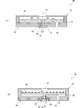
- FIG. 1A and 1B are sectional views of a pressure reducing valve disclosed in Patent Document 1.
- FIG. This pressure reducing valve includes a diaphragm 1 serving as a movable part, a piston 2 serving as a transmission mechanism, a valve housing 7, and a valve seat part 3, a valve body part 4, a support part 5 and a fixed part 6 forming a valve part. .
- the valve body portion 4 is supported around the support portion 5.
- the support part 5 is formed of an elastic beam.
- the fixing part 6 fixes the support part 5 to the valve housing 7.
- each of these members is composed of a plate-like member, and the pressure reducing valve is manufactured by joining the members.
- the upper pressure of the diaphragm (movable part) 1 is P0, the primary pressure upstream of the valve is P1, the pressure downstream of the valve is P2, the area of the valve body part 4 is S1, and the area of the diaphragm (movable part) 1 is S2. .
- the condition for opening the valve as shown in FIG. 1B is (P1-P2) S1 ⁇ (P0-P2) S2. If P2 is higher than the pressure in this condition, the valve is closed, and if P2 is lower, the valve is opened. Thereby, P2 can be kept constant.
- a direct methanol fuel cell has a pump for transporting fuel (methanol).
- a valve-type pump has a check function by a valve, but does not have a stop function (a function to stop a forward flow).
- a stop function a function to stop a forward flow.
- the fuel cartridge incorporated in the fuel cell system may become hot depending on the external environment, and high pressure fluid may be discharged. As a result, excessive fluid may be supplied to the fuel cell or the pump may be destroyed in some cases. Therefore, there is a need for a valve that stops forward flow (hereinafter referred to as a stop valve) when a high-pressure fluid is added.
- a stop valve a valve that stops forward flow
- Patent Document 1 since the pressure reducing valve of Patent Document 1 has a structure in which the support portion 5 is fixed to the valve housing 7 by the fixing portion 6, there is a problem that the valve body becomes taller by the thickness of the fixing portion 6.
- the valve portion has individual differences in each valve portion due to manufacturing variation or the like, in the structure of the pressure reducing valve of Patent Document 1, the pressure of the valve portion with respect to the valve seat is greatly different for each pressure reducing valve. That is, the pressing force required for the piston 2 of the diaphragm 1 to press the valve body portion 4 to open the valve is greatly different for each pressure reducing valve. Therefore, the structure of the pressure reducing valve of Patent Document 1 has a problem that sufficient reliability of fluid control cannot be obtained.
- a first object of the present invention is to provide a stop valve capable of easily aligning the valve and reducing the height of the valve body, and a fuel cell system including the stop valve. .
- a second object of the present invention is a stop valve that can reduce the variation in the pressure of the valve portion relative to the valve seat, even if there is an individual difference in each valve portion due to manufacturing variation of the valve portion, and the like.
- the object is to provide a fuel cell system including a stop valve.
- the stop valve of the present invention has the following configuration in order to solve the above problems.
- valve housing (1) a valve housing; A valve chamber is formed in the valve housing, and a diaphragm is displaced by the pressure of fluid in the valve chamber; A valve portion that blocks or opens the inflow of fluid into the valve chamber by displacement of the diaphragm, and The valve housing communicates with the inflow hole through which the fluid flows into the valve chamber, the outflow hole through which the pump is connected and the fluid flows out of the valve chamber by the suction pressure of the fluid by the pump, and the inflow hole.
- the valve section includes a valve body that contacts the valve seat when the valve section is housed in the opening, and the valve body that is movable in a direction in which the valve body approaches and separates from the valve seat. And a ring-shaped fixing portion that contacts the inner peripheral surface of the opening of the valve housing and fixes the supporting portion when the valve portion is housed in the opening. And The fixing portion has a shape having a plurality of projecting portions that project from a surface of the valve housing on the opening portion side when the valve portion is housed in the opening portion.
- valve portion is fitted into the opening of the valve housing, and is accommodated in the opening of the valve housing.
- the valve body abuts on the valve seat, and the fixing portion that fixes the support portion also abuts on the inner peripheral surface of the opening of the valve housing.
- the said support part supports a valve body movably as mentioned above.
- valve part can be easily replaced by removing it from the opening of the valve housing, improving the yield of the stop valve as a whole. Can also be planned.
- the stop valve in this configuration it is not necessary to precisely position, so that it can be easily aligned.
- the stop valve having this configuration has a structure in which the valve portion is housed in the opening of the valve housing. Therefore, the valve body has a low height corresponding to the thickness of the fixing portion compared to the structure of the pressure reducing valve of Patent Document 1.
- the fixing portion has a shape having a plurality of protruding portions, when the stop valve is aligned and fixed to the substrate (for example, the system housing), the fixing portion is compressed by the valve housing and the substrate. The At that time, only the protruding portion of the fixing portion is pressed against the substrate.
- the fixed portion is less than the case where the entire circumference of the fixed portion protrudes from the opening side surface of the valve housing (that is, the thickness of the fixed portion is longer than the depth of the opening).
- the area pressed by the substrate is reduced, and the volume by which the fixing portion is compressed by the valve housing and the substrate is reduced.
- the material of the protruding portion is preferably rubber.
- the fuel cell system of the present invention has the following configuration in order to solve the above problems.
- the valve can be easily aligned, and the height of the valve body can be reduced. Furthermore, even if there is an individual difference in each valve part due to manufacturing variation of the valve part, etc., it is possible to reduce the variation in the pressure of the valve part with respect to the valve seat.
- FIG. 5A is a top view of the cap part 110 provided in the stop valve 101 of FIG.
- FIG. 5B is a bottom view of the valve housing 130 provided in the stop valve 101 of FIG.
- FIG. 6 is a cross-sectional view taken along the line SS in FIG. It is an expanded sectional view of the valve part 150 shown in FIG.
- FIG. 7 is a cross-sectional view of the stop valve 101 fixed to the system casing 160 in a state where the valve section 150 shown in FIG. 6 is fitted in the opening 147 of the valve casing 130.
- the external perspective view of the valve portion 150 showing the range of the maximum drag that the fixed portion 154 receives from the system housing 160.
- FIG. It is a graph which shows the relationship between the protrusion length of the protrusion part 156 of the fixing
- FIG. 14 is an enlarged cross-sectional view of the valve housing 230 and the valve portion 250 taken along the line TT shown in FIG. 13.
- FIG. 2A is a schematic cross-sectional view of the stop valve 90 in a state where the valve is closed
- FIG. 2B is a schematic cross-sectional view of the stop valve 90 in a state where the valve is open.
- the stop valve 90 includes a diaphragm 20 serving as a movable portion, a valve housing 30 that forms a valve chamber 40 together with the diaphragm 20, a cap portion 10 joined to the valve housing 30, and a valve portion 50 having a valve body portion 51. Consists of.
- the valve housing 30 is formed with an inflow hole 43 through which the fluid flows into the valve chamber 40 and an outflow hole 49 through which the fluid flows out of the valve chamber 40 due to the suction pressure of the fluid by the pump.
- the diaphragm 20 has a pusher 23 that is a transmission mechanism, and is displaced by the pressure of the fluid in the valve chamber 40.
- the pusher 23 presses the valve body unit 51.
- the valve portion 50 has a ring-shaped valve protrusion 55 formed on the inflow hole 43 side of the valve body portion 51, and the valve protrusion 55 is disposed so as to abut on a valve seat 48 positioned at the periphery of the inflow hole 43.
- the valve body 51 abuts or separates from the valve seat 48 due to the displacement of the diaphragm 20 to block or open the inflow of fluid from the inflow hole 43 to the valve chamber 40.
- the cap part 10 is formed with a hole part 15 communicating with the outside air on the upper surface. As a result, atmospheric pressure is applied to the upper part of the diaphragm 20.
- the stop valve 90 is configured such that when the fluid pressure reaches a set pressure, the valve unit 50 automatically opens and closes using the pressure difference. More specifically, the pressure of the atmosphere above the diaphragm 20 is P0, the primary pressure upstream of the valve is P1, and the pressure downstream of the valve is P2, and the area of the valve body 51 (here, the valve body 51 includes a ring-shaped valve). S1 is the area determined by the diameter of the region surrounded by the valve protrusion 55 because the protrusion 55 is formed, S2 is the area of the diaphragm 20, and Fs is the force that the valve body 51 is biased upward. At this time, from the balance of pressure, the condition for opening the valve unit 50 as shown in FIG.
- FIG. 3 is a system configuration diagram of the fuel cell system 100 including the stop valve 101 according to the first embodiment of the present invention.
- the fuel cell system 100 includes a fuel cartridge 102 that stores methanol as a fuel, a stop valve 101, a pump 103 that transports methanol, and a power generation cell 104 that receives the supply of methanol from the pump 103 and generates power. .
- a direct methanol fuel cell includes a pump 103 that transports methanol as a fuel.
- the valve-type pump 103 has a check function by a valve, but does not have a stop function.
- the upstream pressure forward pressure
- the methanol flows even when the pump 103 is not operated.
- a stop valve 101 that is used in combination with the pump 103 and opens and closes the valve using the pump pressure.
- the stop valve 101 includes a valve housing 130 that constitutes a valve chamber 140 together with the diaphragm 120.
- the valve housing 130 is formed with an inflow hole 143 to which the fuel cartridge 102 is connected via the inflow path 163 and an outflow hole 149 to which the pump 103 is connected via the outflow path 165.
- the stop valve 101 is mounted on the surface of a system housing 160 made of polyphenylene sulfide (PPS) resin, in which an inflow path 163 and an outflow path 165 are formed, via O-rings 161 and 162 that prevent leakage.
- PPS polyphenylene sulfide
- methanol flows from the fuel cartridge 102 into the valve chamber 140 through the inflow path 163 and the inflow hole 143. Then, methanol flows out from the valve chamber 140 to the pump 103 through the outflow passage 165 and the outflow hole 149 by the suction pressure of methanol by the pump 103. Then, methanol is supplied to the power generation cell 104 by the pump 103.
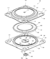
- FIG. 4 is an exploded perspective view of the stop valve 101 according to the first embodiment.
- FIG. 5A is a top view of the cap part 110 provided in the stop valve 101 of FIG.
- FIG. 5B is a bottom view of the valve housing 130 provided in the stop valve 101 of FIG.
- FIG. 6 is a cross-sectional view taken along the line SS in FIG.
- the stop valve 101 includes a cap part 110, a diaphragm 120 serving as a movable part, a valve housing 130, and a valve part 150, as shown in an exploded perspective view in FIG. 4.
- the valve housing 130 has a substantially square plate shape.
- the valve housing 130 is formed with an inflow hole 143 through which the fluid flows into the valve chamber 140 and an outflow hole 149 through which the fluid flows out from the valve chamber 140 due to the suction pressure of the fluid by the pump 103. ing.
- valve casing 130 has a cap section 110 and a screw fixing hole 131 for fixing the valve casing 130 to the system casing 160 and a mounting section 134 on which the peripheral edge 121 of the diaphragm 120 is mounted. And are formed.
- the valve housing 130 has a protruding portion 144 with which the diaphragm 120 abuts when the valve portion 150 releases the inflow of methanol from the inflow hole 143 into the valve chamber 140.
- a flow path 145 that allows methanol to pass from the inside to the outside of the protruding portion 144 is formed around the inflow hole 143 on the bottom surface 141 of the valve chamber 140 that faces the diaphragm 120.
- valve housing 130 is fitted with an opening 147 for accommodating the valve portion 150 by fitting the valve portion 150 from the mounting surface 146 side of the valve housing 130.
- a valve seat 148 located at the periphery of the inflow hole 143 is formed.
- the materials 134, 141, 144, 145, and 148 that contact the methanol of the valve housing 130 are made of a resin having high methanol resistance, such as PPS (Polyphenylene sulfide) resin.
- the material of the edge 132 that does not contact the methanol of the housing 130 is made of metal.
- the valve housing 130 is formed by an insert mold in which an edge 132 of a metal part is inserted into a mold and is injection-molded.
- the diaphragm 120 has a pusher 123 as a transmission mechanism at the center, and the peripheral portion 121 is formed in a disk shape that is thicker than the central portion 122.
- the material of the diaphragm 120 is a rubber having high methanol resistance, such as ethylene propylene rubber or silicone rubber.
- Diaphragm 120 constitutes valve chamber 140 together with valve casing 130 with peripheral edge 121 placed on valve casing 130.
- the central part 122 inside the peripheral part 121 is displaced by the pressure of the fluid in the valve chamber 140.
- the pusher 123 presses the valve body portion 151.
- the liquid When the liquid is used as the fluid for the stop valve 101, the liquid has a large surface tension, so that a larger fluid flow path is required than when the gas is used as the fluid for the stop valve 101.
- the stop valve 101 of this embodiment since the material of the diaphragm 120 is rubber, the movable range of the diaphragm 120 is larger than when the diaphragm 120 is formed of silicon or metal. Therefore, the stop valve 101 of this embodiment can secure a sufficient methanol flow path.
- the valve unit 150 has a substantially circular shape. As will be described in detail later, the valve body 151 abuts or separates from the valve seat 148 due to the displacement of the diaphragm 120 to block or open the flow of fluid from the inflow hole 143 to the valve chamber 140.
- the cap part 110 has a substantially square plate shape, and is formed by punching and drawing a stainless steel plate with a mold.
- the cap part 110 is formed with a screw hole 111 for fixing the cap part 110 and the valve casing 130 to the system casing 160.
- the edge 116 of the metal cap part 110 is joined to the metal edge 132 of the valve housing 130 by welding in a state where the diaphragm 120 is placed on the placing part 134.
- the peripheral part 114 of the cap part 110 is joined, the peripheral part 121 of the diaphragm 120 is pressed to hold the peripheral part 121 together with the mounting part 134.
- a hole 115 communicating with outside air is formed in the central portion 113 of the cap portion 110.
- atmospheric pressure is applied to the upper part of the diaphragm 120.
- a stainless steel pressure receiving plate 125 made of a circular metal that receives a differential pressure between the atmospheric pressure and the internal pressure of the valve chamber 140 is joined to the diaphragm 120.
- the stop valve 101 is configured to automatically open and close the valve unit 150 using the pressure difference when the fluid pressure reaches the set pressure. ing.
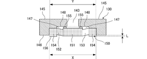
- FIG. 7 is an enlarged cross-sectional view of the valve portion 150 shown in FIG.
- FIG. 8 is an external perspective view of the valve portion 150 shown in FIG.
- FIG. 8A is a view of the valve portion 150 as viewed from the front surface side
- FIG. 8B is a view of the valve portion 150 as viewed from the back surface side.
- the valve unit 150 has a substantially disk shape and is made of rubber having high methanol resistance, such as silicone rubber.
- the valve unit 150 contacts or separates from the valve seat 148 due to the displacement of the diaphragm 120, and a valve body unit 151 that blocks or releases the inflow of fluid (methanol) from the inflow hole 143 to the valve chamber 140.
- a support portion 152 that supports the valve body portion 151 movably in a direction toward and / or away from the valve seat 148; a hole portion 153 that allows methanol to pass through; and a valve portion 150 that is an opening portion.
- an annular fixing portion 154 that contacts the inner peripheral surface of the opening 147 of the valve housing 130 and fixes the support portion 152 when housed in the valve housing 147.
- valve body portion 151 is formed with a ring-shaped valve projection 155 on the inflow hole 43 side, but the valve projection 155 is not necessarily formed.
- valve protrusion 155 of the valve body 151 comes into contact with the valve seat 148 when the valve 150 is housed in the opening 147, and the valve body 151 flows from the inlet hole 143 to the valve chamber 140.
- valve seat 148 is pressurized in a direction to block the inflow of the valve.
- the valve body 151 is separated from the valve seat 148 when the diaphragm 120 is lowered and pushed down by the diaphragm 120, and the inflow hole 143 and the hole 153 communicate with each other to release the inflow of methanol into the valve chamber 140.
- the annular fixing portion 154 protrudes from the mounting surface 146 on the opening 147 side of the valve housing 130 when the valve portion 150 is accommodated in the opening 147.
- the six projecting portions 156 have 360 ° as one round of the annular fixing portion 154, and connect the central angle of the fan-shaped projecting portion 156 (the both ends of the protruding portion 156 and the center of the fixing portion 154).
- the fixing portion 154 is formed so as to satisfy the relationship 1/20 ⁇ C ⁇ ⁇ / 360 ° ⁇ 1/2.
- the outer diameter X of the fixing portion 154 is equal to or larger than the inner diameter Y of the opening 147.
- FIG. 9 is a cross-sectional view of the stop valve 101 fixed to the system casing 160 in a state where the valve section 150 shown in FIG. 6 is fitted in the opening 147 of the valve casing 130.
- FIG. 10 is a valve portion showing a range of the maximum drag that the fixing portion 154 receives from the system housing 160 when the fixing portion 154 of the valve portion 150 shown in FIG. 9 is compressed by the valve housing 130 and the system housing 160.
- FEM Finite Element Method
- the cap part 110 is accommodated in the opening part 147 of the valve casing 130 joined by the above-described welding.
- valve portion 150 when the valve portion 150 is accommodated in the opening 147 of the valve housing 130, the valve body portion 151 comes into contact with the valve seat 148 and the fixing portion 154 for fixing the support portion 152 is also provided as shown in FIG. It contacts the inner peripheral surface of the opening 147 of the valve housing 130. And the said support part 152 supports the valve body part 151 movably as mentioned above.
- the stop valve 101 of this embodiment it is only necessary to fit the valve portion 150 into the opening portion 147. That is, when the stop valve 101 of this embodiment is manufactured, the valve body 151 comes into contact with or separates from the valve seat 148 according to the displacement of the diaphragm 120 as in the pressure reducing valve of Patent Document 1 shown in FIG. Therefore, it is not necessary to fix the support portion 152 to the valve housing 130 in such a manner. Therefore, in the structure of the stop valve 101 of this embodiment, this precise alignment is unnecessary.
- the valve portion 150 opens the opening portion of the valve housing 130 when the stop valve 101 is aligned and fixed to the system housing 160. 147 can be prevented from falling. Therefore, in this embodiment, mounting work when mounting the stop valve 101 to the system housing 160 is facilitated.
- the inner diameter Y of the opening 147 and the outer diameter X of the fixing portion 154 satisfy the relationship of 1 ⁇ Y / X ⁇ 1.2.
- the valve unit 150 may fall from the valve housing 130.
- 1.2 ⁇ Y / X it is difficult to insert the valve unit 150 into the valve housing 130.
- valve portion 150 when there is an abnormality in the valve portion 150 when manufacturing the stop valve 101 of this embodiment, the valve portion 150 can be easily replaced by being removed from the opening 147 of the valve housing 130. The yield of the entire 101 can also be improved.
- the stop valve 101 in this embodiment since the stop valve 101 of this embodiment has a structure in which the valve portion 150 is housed in the opening 147 of the valve housing 130, the thickness of the fixed portion 154 is smaller than that of the pressure reducing valve structure of Patent Document 1. Can reduce the height of the valve body.
- the annular fixing portion 154 is formed when the valve portion 150 is accommodated in the opening portion 147 as shown in FIGS. 7 and 8B.
- the material of the protruding portion 156 is rubber.
- the stop valve 101 of this embodiment compared to the case where the entire circumference of the fixed portion 154 protrudes from the mounting surface 146 of the valve housing 130 (that is, the thickness of the fixed portion 154 is longer than the depth of the opening 147).
- the area where the fixing portion 154 is pressed from the system housing 160 is reduced, and the volume of the fixing portion 154 compressed by the valve housing 130 and the system housing 160 is reduced.
- FIG. 11 is a graph showing the relationship between the protruding length L of the protruding portion 156 of the fixed portion 154 of the valve portion 150 and the pressurization of the valve portion 150 against the valve seat 148 shown in FIG.
- the graph shown in FIG. 11 shows the result calculated by FEM.
- the plurality of projecting portions 156 has a circumference of the annular fixed portion 154 of 360 °, and the central angle of the fan-shaped projecting portion 156 (the both ends of the projecting portion 156 and the center of the fixing portion 154). Is formed so as to satisfy a relationship of 1/20 ⁇ C ⁇ ⁇ / 360 ° ⁇ 1/2.
- the projecting length L of the projecting part 156 of each valve unit 150 is set to the projecting length L due to manufacturing variation of the valve unit 150 or the like. Even if there is an individual difference, it is possible to reduce variations in the pressure of the valve portion 150 with respect to the valve seat 148.
- the stop valve 101 in this embodiment it is possible to reduce variations in pressing force required for the pusher 123 of the diaphragm 120 to press the valve body portion 151 and open the valve portion 150. Therefore, the reliability of the valve body can be improved.
- the parts 134, 141, 144, 145 and 148 in contact with methanol of the valve housing 130 are all made of resin, and the material of the diaphragm 120 and the valve part 150 is also rubber, so that metal ions It does not elute in methanol (see FIG. 9). Therefore, in the stop valve 101 of this embodiment, the DMFC characteristic does not deteriorate due to elution of metal ions.
- the fuel cell system 100 including the stop valve 101 has the same effect.
- FIG. 12 is an external perspective view of the valve portion 250 provided in the stop valve 201 according to the second embodiment of the present invention.
- 12A is a view of the valve portion 250 as viewed from the front surface side
- FIG. 12B is a view of the valve portion 250 as viewed from the back surface side.
- FIG. 13 is an enlarged perspective view around the inflow hole 143 of the valve housing 230 in the stop valve 201 according to the second embodiment of the present invention.
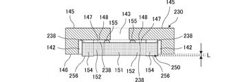
- FIG. 14 is an enlarged cross-sectional view of the valve housing 230 and the valve portion 250 taken along the line TT shown in FIG.
- FIG. 13 is a perspective view showing the state in which the valve portion 250 is housed in the opening 147 of the valve housing 230.
- the difference between the stop valve 201 according to this embodiment and the stop valve 101 according to the first embodiment is a valve portion 250 and a valve housing 230. Other configurations are the same.
- the valve portion 250 is different from the valve portion 150 in that the hole portion 153 is not formed as shown in FIG.
- the annular fixing portion 154 has a mounting surface 146 on the opening 147 side of the valve housing 230 when the valve portion 250 is housed in the opening 147 of the valve housing 230.
- the stop valve 201 is fixed to the system casing 160 and the fixing section 154 is compressed by the valve casing 230 and the system casing 160 in the fixing section 154.
- a fan-shaped plate 257 that stabilizes the posture of the valve portion 250 is formed around each protruding portion 256.
- valve housing 230 is configured such that the valve housing 250 is housed in the opening 147 and the stop valve 201 is fixed to the system housing 160.
- the valve housing 130 is different from the valve housing 130 in that a flow channel 142 communicating with the inflow passage 163 and a housing protrusion 235 that contacts the valve portion 250 and forms the flow channel 238 together with the valve portion 250 are formed.
- valve portion 250 is fitted into the opening portion 147 from the mounting surface 146 side of the valve housing 230, and is stored in the opening portion 147 of the valve housing 230 to which the cap portion 110 is joined.
- the inflow hole 143 of the stop valve 201 and the inflow path 163 of the system housing 160 and the outflow hole 149 of the stop valve 201 and the system housing are fitted with the valve portion 250 fitted in the opening 147 of the valve housing 230.
- the outflow channel 165 of the body 160 is aligned.
- the fluid flowing in from the inflow passage 163 of the system housing 160 flows between the flow path 142, the valve protrusion 155, and the housing protrusion 235. It passes through the enclosed flow path 238 and flows into the valve chamber 140.
- valve part 250 it is not necessary to form the hole portion 153 through which the fluid passes in the valve portion 250. Therefore, according to this embodiment, since the valve part 250 can be made into a simple structure without the hole part 153, the manufacturing cost of the valve part 250 can be reduced significantly.
- methanol is used as a highly active fluid, but the fluid may be any of gas, liquid, gas-liquid mixed flow, solid-liquid mixed flow, solid-gas mixed flow, and the like.
- Valve housing 10 Cap part 15 Hole part 20 Diaphragm 23 Pusher 30 Valve housing 40 Valve chamber 43 Inflow hole 48 Valve seat 49 Outlet hole 50 Valve Part 51 Valve body part 55 Valve protrusion 90 Stop valve 100 Fuel cell system 101, 201 Stop valve 102 Fuel cartridge 103 Pump 104 Power generation cell 110 Cap part 111 Hole 113 Center part 114 Edge part 115 Hole part 116 Edge 120 Diaphragm 121 Edge Portion portion 122 Central portion 123 Pusher 125 Pressure receiving plate 130, 230 Valve housing 131 Hole 132 Edge 134 Placement portion 140 Valve chamber 141 Bottom surface 142 Channel 143 Inflow hole 144 Projection portion 145 Channel 147 Opening portion 148 Valve seat 149 Outflow hole 50, 250 valve 151 valve body 152 supporting portion 153 hole portion 154 fixed portion 155 valve boss 156,256 projecting portion 160 System housing 161 ring
Landscapes
- Engineering & Computer Science (AREA)
- General Engineering & Computer Science (AREA)
- Mechanical Engineering (AREA)
- Sustainable Energy (AREA)
- Manufacturing & Machinery (AREA)
- Sustainable Development (AREA)
- Life Sciences & Earth Sciences (AREA)
- Chemical & Material Sciences (AREA)
- Chemical Kinetics & Catalysis (AREA)
- Electrochemistry (AREA)
- General Chemical & Material Sciences (AREA)
- Check Valves (AREA)
- Safety Valves (AREA)
- Fuel Cell (AREA)
- Fluid-Driven Valves (AREA)
Abstract
L'invention porte sur un clapet de non-retour grâce auquel il est possible d'aligner facilement un clapet, et dont le corps principal de clapet est réduit en hauteur, et sur un système de pile à combustible. Une unité de clapet (150) comprend : une partie corps de clapet (151) qui entre en contact avec une base de clapet (148) lorsque l'unité de clapet (150) est encastrée dans une ouverture (147) ; une unité support (152) qui supporte la partie corps de clapet (151) de telle sorte que la partie corps de clapet (151) peut se rapprocher et s'éloigner de la base de clapet (148) ; un trou (153) ; et une unité de fixation (154) qui entre en contact avec la surface de périmètre intérieur de l'ouverture (147) d'un boîtier de clapet (130) lorsque l'unité de clapet (150) est encastrée dans l'ouverture (147), et qui fixe l'unité support (152). L'unité de fixation (154) présente une partie saillante (156) qui fait saillie sur une surface de montage (146) du boîtier de clapet (130) lorsque l'unité de clapet (150) est encastrée dans l'ouverture (147). En montant l'unité de clapet (150) dans l'ouverture (147), l'unité de clapet (150) est encastrée dans l'ouverture (147) du boîtier de clapet (130).
Priority Applications (3)
| Application Number | Priority Date | Filing Date | Title |
|---|---|---|---|
| JP2013509824A JP5582250B2 (ja) | 2011-04-12 | 2012-03-01 | 順止バルブ、燃料電池システム |
| CN201280015483.1A CN103443516B (zh) | 2011-04-12 | 2012-03-01 | 止进阀、燃料电池系统 |
| US14/049,252 US9593780B2 (en) | 2011-04-12 | 2013-10-09 | Forward check valve and fuel cell system |
Applications Claiming Priority (2)
| Application Number | Priority Date | Filing Date | Title |
|---|---|---|---|
| JP2011088083 | 2011-04-12 | ||
| JP2011-088083 | 2011-04-12 |
Related Child Applications (1)
| Application Number | Title | Priority Date | Filing Date |
|---|---|---|---|
| US14/049,252 Continuation US9593780B2 (en) | 2011-04-12 | 2013-10-09 | Forward check valve and fuel cell system |
Publications (1)
| Publication Number | Publication Date |
|---|---|
| WO2012140968A1 true WO2012140968A1 (fr) | 2012-10-18 |
Family
ID=47009150
Family Applications (1)
| Application Number | Title | Priority Date | Filing Date |
|---|---|---|---|
| PCT/JP2012/055180 Ceased WO2012140968A1 (fr) | 2011-04-12 | 2012-03-01 | Clapet de non-retour et système de pile à combustible |
Country Status (4)
| Country | Link |
|---|---|
| US (1) | US9593780B2 (fr) |
| JP (1) | JP5582250B2 (fr) |
| CN (1) | CN103443516B (fr) |
| WO (1) | WO2012140968A1 (fr) |
Cited By (1)
| Publication number | Priority date | Publication date | Assignee | Title |
|---|---|---|---|---|
| JPWO2016153004A1 (ja) * | 2015-03-25 | 2017-12-07 | 株式会社タクミナ | 逆止弁および弁体 |
Families Citing this family (4)
| Publication number | Priority date | Publication date | Assignee | Title |
|---|---|---|---|---|
| EP3022418B1 (fr) * | 2013-07-15 | 2021-09-15 | Accurate Repetition Pty Limited | Système perfectionné de soupape de dérivation turbocompressé ou suralimenté pour véhicule motorisé |
| EP2883566B1 (fr) | 2013-12-11 | 2017-05-24 | Gambro Lundia AB | Système de traitement sanguin extracorporel et unité de soupape pour pré/post-infusion |
| USD862656S1 (en) * | 2016-10-31 | 2019-10-08 | Juan Antonio Urtuza Guerra | Valve diaphragm |
| FR3090792B1 (fr) * | 2018-12-21 | 2021-01-22 | Commissariat Energie Atomique | Dispositif de vanne fluidique anti-retour |
Citations (2)
| Publication number | Priority date | Publication date | Assignee | Title |
|---|---|---|---|---|
| JP2008082543A (ja) * | 2006-08-29 | 2008-04-10 | Canon Inc | 流体配管の接続機構とその製造方法、及び流体配管の接続機構を備えた燃料電池システム |
| WO2009157474A1 (fr) * | 2008-06-27 | 2009-12-30 | 株式会社村田製作所 | Microsoupape et élément de siège de soupape |
Family Cites Families (12)
| Publication number | Priority date | Publication date | Assignee | Title |
|---|---|---|---|---|
| US6280867B1 (en) * | 1997-12-05 | 2001-08-28 | Griff Consulting, Inc. | Apparatus for pumping a fluid in a fuel cell system |
| US7874498B2 (en) * | 2000-10-25 | 2011-01-25 | Grundfos Pumps Corporation | Water control fixture having thermostatically controlled bypass valve |
| JP2004293777A (ja) * | 2003-03-11 | 2004-10-21 | Tokico Ltd | 緊急離脱カプラ |
| US7524573B2 (en) * | 2004-02-23 | 2009-04-28 | Kabushiki Kaisha Toshiba | Fuel cell having inner and outer periphery seal members |
| JP2007040322A (ja) * | 2005-07-29 | 2007-02-15 | Canon Inc | リリーフバルブ、その製造方法および燃料電池 |
| JP2007210299A (ja) * | 2006-02-13 | 2007-08-23 | Seiko Epson Corp | 弁装置及び液体噴射装置 |
| CN101375093B (zh) * | 2006-08-29 | 2010-06-02 | 佳能株式会社 | 流体管道的连接机构及其制造方法和包括其的燃料电池系统 |
| JP5121188B2 (ja) * | 2006-08-29 | 2013-01-16 | キヤノン株式会社 | 圧力制御弁、圧力制御弁の製造方法、及び圧力制御弁を搭載した燃料電池システム |
| JP2009021050A (ja) * | 2007-07-10 | 2009-01-29 | Seiko Instruments Inc | 燃料電池 |
| JP2009127704A (ja) * | 2007-11-21 | 2009-06-11 | Alps Electric Co Ltd | バルブ装置及び多層化基板 |
| US8196581B2 (en) * | 2008-04-14 | 2012-06-12 | Jeffrey Evan Bozanic | Mouthpiece supply valve |
| US8323247B2 (en) * | 2009-05-08 | 2012-12-04 | The Alfred E. Mann Foundation For Scientific Research | Fluid transfer devices with fluid bypass and ambulatory infusion devices including same |
-
2012
- 2012-03-01 WO PCT/JP2012/055180 patent/WO2012140968A1/fr not_active Ceased
- 2012-03-01 CN CN201280015483.1A patent/CN103443516B/zh active Active
- 2012-03-01 JP JP2013509824A patent/JP5582250B2/ja active Active
-
2013
- 2013-10-09 US US14/049,252 patent/US9593780B2/en active Active
Patent Citations (2)
| Publication number | Priority date | Publication date | Assignee | Title |
|---|---|---|---|---|
| JP2008082543A (ja) * | 2006-08-29 | 2008-04-10 | Canon Inc | 流体配管の接続機構とその製造方法、及び流体配管の接続機構を備えた燃料電池システム |
| WO2009157474A1 (fr) * | 2008-06-27 | 2009-12-30 | 株式会社村田製作所 | Microsoupape et élément de siège de soupape |
Cited By (2)
| Publication number | Priority date | Publication date | Assignee | Title |
|---|---|---|---|---|
| JPWO2016153004A1 (ja) * | 2015-03-25 | 2017-12-07 | 株式会社タクミナ | 逆止弁および弁体 |
| US10473224B2 (en) | 2015-03-25 | 2019-11-12 | Tacmina Corporation | Check valve and valve body |
Also Published As
| Publication number | Publication date |
|---|---|
| JPWO2012140968A1 (ja) | 2014-07-28 |
| CN103443516B (zh) | 2015-06-10 |
| US9593780B2 (en) | 2017-03-14 |
| JP5582250B2 (ja) | 2014-09-03 |
| US20140038083A1 (en) | 2014-02-06 |
| CN103443516A (zh) | 2013-12-11 |
Similar Documents
| Publication | Publication Date | Title |
|---|---|---|
| JP5582250B2 (ja) | 順止バルブ、燃料電池システム | |
| US9574674B2 (en) | Valve, fluidic apparatus, and fluid-supplying apparatus | |
| JP5425831B2 (ja) | 締切り機構付き減圧弁 | |
| CN101405527B (zh) | 一体化双膜隔膜阀 | |
| JP5790786B2 (ja) | バルブ、燃料電池システム | |
| JP5527101B2 (ja) | 順止バルブ、燃料電池システム | |
| JP5565464B2 (ja) | 順止バルブ、燃料電池システム | |
| JP5510551B2 (ja) | 順止バルブ、燃料電池システム | |
| JP5510142B2 (ja) | 高圧遮断バルブ、燃料カートリッジ、及び燃料電池システム | |
| US5107885A (en) | Check valve | |
| JP5780304B2 (ja) | バルブ、燃料電池システム | |
| JP5817314B2 (ja) | 順止バルブ、燃料電池システム | |
| JPH11182706A (ja) | 逆止機能付定流量弁 | |
| JP5664014B2 (ja) | 順止バルブ、燃料電池システム | |
| JP2001153244A (ja) | チェック弁内蔵バルブ | |
| CN215861760U (zh) | 一种易装配的燃气比例阀阀芯组件及燃气比例阀 | |
| CN111457148A (zh) | 先导式电磁阀 | |
| JP2005293127A (ja) | 整圧器 |
Legal Events
| Date | Code | Title | Description |
|---|---|---|---|
| 121 | Ep: the epo has been informed by wipo that ep was designated in this application |
Ref document number: 12771766 Country of ref document: EP Kind code of ref document: A1 |
|
| ENP | Entry into the national phase |
Ref document number: 2013509824 Country of ref document: JP Kind code of ref document: A |
|
| NENP | Non-entry into the national phase |
Ref country code: DE |
|
| 122 | Ep: pct application non-entry in european phase |
Ref document number: 12771766 Country of ref document: EP Kind code of ref document: A1 |