EP3022430B1 - Tube de support, élément filtre et système de filtration pourvu d'un tube de support, ainsi que procédé et dispositif permettant de produire le tube support - Google Patents
Tube de support, élément filtre et système de filtration pourvu d'un tube de support, ainsi que procédé et dispositif permettant de produire le tube support Download PDFInfo
- Publication number
- EP3022430B1 EP3022430B1 EP14725472.6A EP14725472A EP3022430B1 EP 3022430 B1 EP3022430 B1 EP 3022430B1 EP 14725472 A EP14725472 A EP 14725472A EP 3022430 B1 EP3022430 B1 EP 3022430B1
- Authority
- EP
- European Patent Office
- Prior art keywords
- support tube
- mandrel
- longitudinal
- webs
- longitudinal webs
- Prior art date
- Legal status (The legal status is an assumption and is not a legal conclusion. Google has not performed a legal analysis and makes no representation as to the accuracy of the status listed.)
- Active
Links
Images


Classifications
-
- B—PERFORMING OPERATIONS; TRANSPORTING
- B01—PHYSICAL OR CHEMICAL PROCESSES OR APPARATUS IN GENERAL
- B01D—SEPARATION
- B01D46/00—Filters or filtering processes specially modified for separating dispersed particles from gases or vapours
- B01D46/0002—Casings; Housings; Frame constructions
- B01D46/0005—Mounting of filtering elements within casings, housings or frames
-
- B—PERFORMING OPERATIONS; TRANSPORTING
- B29—WORKING OF PLASTICS; WORKING OF SUBSTANCES IN A PLASTIC STATE IN GENERAL
- B29C—SHAPING OR JOINING OF PLASTICS; SHAPING OF MATERIAL IN A PLASTIC STATE, NOT OTHERWISE PROVIDED FOR; AFTER-TREATMENT OF THE SHAPED PRODUCTS, e.g. REPAIRING
- B29C45/00—Injection moulding, i.e. forcing the required volume of moulding material through a nozzle into a closed mould; Apparatus therefor
- B29C45/17—Component parts, details or accessories; Auxiliary operations
- B29C45/26—Moulds
- B29C45/261—Moulds having tubular mould cavities
-
- B—PERFORMING OPERATIONS; TRANSPORTING
- B01—PHYSICAL OR CHEMICAL PROCESSES OR APPARATUS IN GENERAL
- B01D—SEPARATION
- B01D46/00—Filters or filtering processes specially modified for separating dispersed particles from gases or vapours
- B01D46/0001—Making filtering elements
-
- B—PERFORMING OPERATIONS; TRANSPORTING
- B01—PHYSICAL OR CHEMICAL PROCESSES OR APPARATUS IN GENERAL
- B01D—SEPARATION
- B01D46/00—Filters or filtering processes specially modified for separating dispersed particles from gases or vapours
- B01D46/24—Particle separators, e.g. dust precipitators, using rigid hollow filter bodies
- B01D46/2403—Particle separators, e.g. dust precipitators, using rigid hollow filter bodies characterised by the physical shape or structure of the filtering element
- B01D46/2411—Filter cartridges
-
- B—PERFORMING OPERATIONS; TRANSPORTING
- B29—WORKING OF PLASTICS; WORKING OF SUBSTANCES IN A PLASTIC STATE IN GENERAL
- B29C—SHAPING OR JOINING OF PLASTICS; SHAPING OF MATERIAL IN A PLASTIC STATE, NOT OTHERWISE PROVIDED FOR; AFTER-TREATMENT OF THE SHAPED PRODUCTS, e.g. REPAIRING
- B29C45/00—Injection moulding, i.e. forcing the required volume of moulding material through a nozzle into a closed mould; Apparatus therefor
- B29C45/17—Component parts, details or accessories; Auxiliary operations
- B29C45/26—Moulds
- B29C45/33—Moulds having transversely, e.g. radially, movable mould parts
-
- B—PERFORMING OPERATIONS; TRANSPORTING
- B29—WORKING OF PLASTICS; WORKING OF SUBSTANCES IN A PLASTIC STATE IN GENERAL
- B29C—SHAPING OR JOINING OF PLASTICS; SHAPING OF MATERIAL IN A PLASTIC STATE, NOT OTHERWISE PROVIDED FOR; AFTER-TREATMENT OF THE SHAPED PRODUCTS, e.g. REPAIRING
- B29C45/00—Injection moulding, i.e. forcing the required volume of moulding material through a nozzle into a closed mould; Apparatus therefor
- B29C45/17—Component parts, details or accessories; Auxiliary operations
- B29C45/26—Moulds
- B29C45/37—Mould cavity walls, i.e. the inner surface forming the mould cavity, e.g. linings
-
- F—MECHANICAL ENGINEERING; LIGHTING; HEATING; WEAPONS; BLASTING
- F02—COMBUSTION ENGINES; HOT-GAS OR COMBUSTION-PRODUCT ENGINE PLANTS
- F02M—SUPPLYING COMBUSTION ENGINES IN GENERAL WITH COMBUSTIBLE MIXTURES OR CONSTITUENTS THEREOF
- F02M35/00—Combustion-air cleaners, air intakes, intake silencers, or induction systems specially adapted for, or arranged on, internal-combustion engines
- F02M35/02—Air cleaners
- F02M35/0201—Housings; Casings; Frame constructions; Lids; Manufacturing or assembling thereof
- F02M35/0202—Manufacturing or assembling; Materials for air cleaner housings
-
- F—MECHANICAL ENGINEERING; LIGHTING; HEATING; WEAPONS; BLASTING
- F02—COMBUSTION ENGINES; HOT-GAS OR COMBUSTION-PRODUCT ENGINE PLANTS
- F02M—SUPPLYING COMBUSTION ENGINES IN GENERAL WITH COMBUSTIBLE MIXTURES OR CONSTITUENTS THEREOF
- F02M35/00—Combustion-air cleaners, air intakes, intake silencers, or induction systems specially adapted for, or arranged on, internal-combustion engines
- F02M35/02—Air cleaners
- F02M35/024—Air cleaners using filters, e.g. moistened
- F02M35/02475—Air cleaners using filters, e.g. moistened characterised by the shape of the filter element
- F02M35/02483—Cylindrical, conical, oval, spherical or the like filter elements; wounded filter elements
-
- B—PERFORMING OPERATIONS; TRANSPORTING
- B01—PHYSICAL OR CHEMICAL PROCESSES OR APPARATUS IN GENERAL
- B01D—SEPARATION
- B01D2265/00—Casings, housings or mounting for filters specially adapted for separating dispersed particles from gases or vapours
- B01D2265/06—Details of supporting structures for filtering material, e.g. cores
-
- B—PERFORMING OPERATIONS; TRANSPORTING
- B29—WORKING OF PLASTICS; WORKING OF SUBSTANCES IN A PLASTIC STATE IN GENERAL
- B29L—INDEXING SCHEME ASSOCIATED WITH SUBCLASS B29C, RELATING TO PARTICULAR ARTICLES
- B29L2023/00—Tubular articles
- B29L2023/003—Tubular articles having irregular or rough surfaces
-
- B—PERFORMING OPERATIONS; TRANSPORTING
- B29—WORKING OF PLASTICS; WORKING OF SUBSTANCES IN A PLASTIC STATE IN GENERAL
- B29L—INDEXING SCHEME ASSOCIATED WITH SUBCLASS B29C, RELATING TO PARTICULAR ARTICLES
- B29L2023/00—Tubular articles
- B29L2023/22—Tubes or pipes, i.e. rigid
-
- F—MECHANICAL ENGINEERING; LIGHTING; HEATING; WEAPONS; BLASTING
- F02—COMBUSTION ENGINES; HOT-GAS OR COMBUSTION-PRODUCT ENGINE PLANTS
- F02M—SUPPLYING COMBUSTION ENGINES IN GENERAL WITH COMBUSTIBLE MIXTURES OR CONSTITUENTS THEREOF
- F02M35/00—Combustion-air cleaners, air intakes, intake silencers, or induction systems specially adapted for, or arranged on, internal-combustion engines
- F02M35/02—Air cleaners
- F02M35/0201—Housings; Casings; Frame constructions; Lids; Manufacturing or assembling thereof
- F02M35/0205—Details, e.g. sensors or measuring devices
- F02M35/0207—Details, e.g. sensors or measuring devices on the clean air side
Definitions
- the invention relates to a support tube made of plastic for a filter element, with a plurality of passage recesses, wherein the support tube is integrally formed and the passage recesses are limited by more than four, in cross-section polygonal, at least partially formed in the longitudinal direction of the support tube longitudinal webs.
- the invention further relates to a filter element and a filter system with such a support tube and a method and an apparatus for its production.
- support tubes made of plastic in filter elements, in particular in filter elements for motor vehicles.
- Such support tubes are also referred to as so-called center tubes and are for example from the DE 10 2011 018 366 A1 known.
- the support tubes serve to support or support a filter medium and are at least partially flowed through by the fluid to be filtered or by the filtered fluid, in particular by air.
- the support tubes on passages, which are separated by longitudinal webs.
- a support tube with a plurality of longitudinal webs and passages is from the EP 1 481 715 A1 known.
- the known support tube consists of several, basket-shaped, stacked support tube elements. To provide such a plurality of support tube elements, however, is relatively complex and therefore expensive to manufacture and assembly. It should be remembered in terms of production costs, that the support tubes in question is a mass-produced article, in which even minor improvements in the manufacture of a single support tube significantly affect the total cost of production.
- Such a one-piece support tube is in the DE 10 2005 040 623 A1 disclosed.
- the longitudinal webs of this known support tube are round in cross-section.
- the support tube can be made even easier and thus cheaper if the longitudinal webs have a polygonal cross-section.
- Further support tubes are for example off GB 1 345 155 A or DE 10 2010 042 424 A1 known.
- Such support tubes are already manufactured by the applicant.
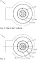
- Fig. 2 - which will be explained below - shows such a known support tube in cross section.
- the support tube is produced by plastic injection molding and has due to the mold used for the preparation of the support tube and a facilitated formation of the support tube longitudinal webs with different shape and different cross section.
- Filter elements with such support tubes are used in filter systems, for example in air filter systems in trucks or construction vehicles, and can usually be used with a freely selectable or randomly resulting rotational position about its longitudinal axis in the housing of the filter system.
- the filter systems often include a fluid sensor for determining the filtered fluid flow.
- the invention is therefore based on the object to provide a support tube, which allows both a reproducible fluid flow and also can be easily and inexpensively manufactured.
- a support tube made of plastic for a filter system wherein the support tube has a plurality of transverse webs and longitudinal webs limited fürgangsausEnglishept and is integrally formed and the fürgangsausEnglishept by more than four, in cross-section polygonal, at least in sections in the longitudinal direction of the support tube formed longitudinal webs are limited, wherein the longitudinal webs are each formed symmetrically to its running in the longitudinal direction of the support tube, the central longitudinal axis of the support tube intersecting center plane.
- the longitudinal webs are thus symmetrical in cross-section or at least with respect to their opposite side edges to the center of the support tube.
- the fluid flow can thereby flow around the longitudinal webs uniformly.
- the polygonal design of the longitudinal webs enables cost-effective production.
- the stability of the support tube is ensured by the number of longitudinal webs.
- all of the longitudinal webs are symmetrical with respect to their center plane.
- the support tube may have any shape in cross section.
- the support tube may have a substantially oval or polygonal cross-section.
- a particularly uniform flow through the support tube and thus a particularly precise measurement of the fluid flow, however, can be achieved in that the support tube has a round cross-section, that is, is formed radially symmetrically to its central longitudinal axis.
- the longitudinal webs are rotationally symmetrical to the central longitudinal axis of the support tube, in order to allow a uniform flow against the support tube from all outer sides.
- all longitudinal webs on the same cross-section are identical, whereby different deflections of the fluid flow depending on the rotational position of the support tube can be reduced or avoided.
- a structurally particularly simple production of the support tube can be achieved in that at least one longitudinal web, in particular all longitudinal webs, have a quadrangular cross-section. At least one longitudinal web, in particular all longitudinal webs, can have a rectangular or trapezoidal cross-section. A trapezoidal cross-section is then particularly preferred when imaginary extensions of the side edges of the longitudinal web outside of the support tube intersect - the center plane intersecting the central longitudinal axis of the support tube. In other words, at least one longitudinal web, preferably all longitudinal webs, may be formed with side flanks which become narrower towards the outside. As a result, the support tube during the injection molding process can be removed much easier.
- the object of the invention is further achieved by a filter element with a support tube described above and with a, preferably annular, filter medium which bears against the longitudinal webs of the support tube on the outside and is supported in the radial direction.
- the filter medium can - in order to provide a large surface available - several times folded against the outside of the support tube. It is understood that the filter element can be provided in a known manner with two-sided end plates.
- a filter system having a housing in which a previously described filter element is arranged, wherein the housing has a fluid inlet, which is fluidically connected to the outside of the filter medium and the housing has a fluid outlet, which fluidly with the inside the support tube is connected, wherein between the support tube and the fluid outlet, a fluid sensor, in particular a fluid mass sensor, is arranged for measuring the fluid flow from the housing.
- a fluid sensor in particular a fluid mass sensor
- a fluid sensor In front of the fluid outlet, a fluid sensor can be arranged which measures at least a portion of the fluid quantity which flows out of the fluid outlet per unit of time. Based on this measurement, the amount of fluid flowing out of the fluid outlet per time can then be determined or extrapolated directly.
- the respective rotational position of the filter element or of the support tube installed in the filter element has a less distorting effect on the fluid flow measurement relative to the fluid inlet than is the case with conventional filter systems.
- the filter element and filter system according to the invention is a filter element or filter system which serves to filter intake air of an internal combustion engine of a motor vehicle.
- the object of the invention is further achieved by a device for injection molding of a support tube described above, wherein the device has a, in particular cylindrical, mandrel whose outer side bounds the inside of the support tube during its manufacture, wherein the device at least three outer elements can be arranged around the mandrel (also Molded parts called) and a, in particular thermoplastic, plastic in the formation of the longitudinal webs of the support tube provided voids of the device between the mandrel and the outer elements can be introduced, wherein the voids symmetrical to its running in the longitudinal direction of the mandrel, the central longitudinal axis of the mandrel intersecting center plane are formed.
- the device has a, in particular cylindrical, mandrel whose outer side bounds the inside of the support tube during its manufacture, wherein the device at least three outer elements can be arranged around the mandrel (also Molded parts called) and a, in particular thermoplastic, plastic in the formation of the longitudinal webs of the support tube provided voids of the
- the device according to the invention for producing the support tube thus comprises at least four elements: a mandrel, which can also be designed in several parts and bounds the inside of the support tube and at least three outer elements which bound the outside of the support tube.
- Mandrel and outer elements touch in the area in which the passages of the support tube are formed.
- voids or cavities are provided, into which plastic is injectable to form the longitudinal webs of the support tube, wherein the longitudinal webs have the shape of the voids.
- the voids are formed such that the longitudinal webs are each formed symmetrically to their running in the longitudinal direction of the support tube, the central longitudinal axis of the support tube intersecting center plane.
- the outer elements can be particularly easily removed from the support tube after the curing of the plastic in the device, if in at least one area between two outer elements and the mandrel, in particular in all areas between two outer elements and the mandrel, a void for a longitudinal ridge is provided.
- the outer elements can thereby be lifted from both sides of the longitudinal webs.
- the device can be structurally particularly simple. The high number of voids and the resulting high number of longitudinal webs enables the production of a mechanically stable support tube.
- the voids are preferably polygonal in order to enable cost-effective production.
- the voids are trapezoidal in cross-section, wherein the side edges of the void away from the mandrel run towards each other, that is, the cross-section of the voids are formed narrowing towards the outside.
- Such voids are both easy to manufacture and easily separable from the resulting support tube.
- the mandrel may have any shape in cross section.
- the mandrel may have a substantially oval or polygonal cross section.
- the voids are rotationally symmetrical to the central longitudinal axis of the mandrel formed to allow a uniform flow against the longitudinal webs of the support tube from all its outer sides and a slight demolding of the support tube from the device.
- all empty spaces have the same cross-section.
- the flow resistance of all longitudinal webs formed in the voids is identical, whereby rotational position-dependent deflections of the fluid can be effectively avoided.
- a structurally particularly simple production of the support tube can be achieved in that at least one empty space, in particular all empty spaces, have a quadrangular cross section.
- the method described is preferably used using the device described above for producing the support tube described above.
- the outer elements are moved radially away from the center of the mandrel after curing of the plastic, in order to avoid damage to the newly formed support tube.
- Method step e) can be carried out in a particularly reproducible and error-free manner if an empty space for a longitudinal web is provided in at least one region between two outer elements and the mandrel, in particular in all regions between two outer elements and the mandrel.
- the method can furthermore be carried out in a very cost-effective manner if the voids are polygonal in cross-section, in particular narrower in cross-section into a trapezoidal shape towards the outside.
- a mandrel used in cross-section of any shape can be used in cross-section of any shape.
- a mandrel having a substantially oval or polygonal cross section may be used.
- a particularly uniform flow through the manufactured support tube can be achieved in that a mandrel is used which has a round cross section, that is, is formed radially symmetrical to its central longitudinal axis.
- voids are used, which are rotationally symmetrical to the central longitudinal axis of the mandrel, to allow a uniform flow against the longitudinal webs of the support tube from all its outer sides and a slight demolding of the support tube from the device.
- all empty spaces used have the same cross-section.
- the flow resistance of all longitudinal webs formed in the voids is identical, whereby rotational position-dependent deflections of the fluid can be effectively avoided.
- a support tube produced in the manner described above and a suitable filter medium for the respective application, for example, via two end plates is connected to each other.
- Fig. 1 shows a filter system 1 according to the invention, here an air filter system, with a filter element 6.
- the filter element 6 has a first end plate 8 and a second end plate 10 and is arranged in a housing 12 having a fluid inlet 14 and a fluid outlet 16.
- the fluid to be cleaned (not shown), here the air to be cleaned, flows in the direction of a first arrow 18 on a filter medium 20 of the filter element 6, which surrounds a central or support tube 22 of the filter element 6 folded several times.
- the filter medium 20 lies directly against the outside of the support tube 22.
- the support tube 22 is integrally formed of plastic and has a plurality of transverse webs and longitudinal webs defining a plurality of through-holes. For reasons of clarity, only a first transverse strut 24, a second transverse strut 26, a first longitudinal strut 28 and a second longitudinal strut 30 are provided with a reference numeral.
- the transverse webs 24, 26 define, together with the longitudinal webs 28, 30, a first through-passage 32.
- the fluid cleaned by the filter medium 20 flows from the outside through the through-passages, for example the first through-hole 32 into the support tube 22, from where the fluid in the direction of a second arrow 34 axially from the support tube 22 and further in the direction of a third arrow 36 flows out of the housing 12.
- the fluid sensor 38 measures a portion of the fluid flow. From this, the total per unit time the filter system 1 and the filter element 6 leaving fluid quantity can be determined. However, the measurement of the fluid sensor 38 only takes place with sufficient precision if there is no or only little vortex formation in the fluid flow. Such vortex formation or other irregularities in the fluid flow occur particularly when the filter element 6 is arranged in different rotated position in the housing 12.
- the inventors have now found that the extent of vortex formation or the homogeneity of the fluid flow is significantly dependent on the shape of the longitudinal webs, for example the longitudinal webs 28, 30.
- Fig. 2 shows a sectional plan view of a filter system 1a according to the prior art, which essentially like the filter system 1 according to Fig. 1 is constructed, but has a disadvantageous support tube 22a.
- the support tube 22a has a plurality of longitudinal webs, of which, for reasons of clarity, only a first longitudinal web 28a and a second longitudinal web 30a are provided with a reference numeral.
- the longitudinal webs 28a and 30a have a different cross section.
- the longitudinal webs 28a, 30a differ in terms of their shape and thereby their flow resistance. This can lead to a different radial inflow of the fluid (not shown) into the center of the support tube 22a.
- Fig. 3 shows a contrast plan view of the filter system 1 according to the invention according to Fig. 1 , Out Fig. 3 It will be seen that all the longitudinal webs, for example the longitudinal webs 28, 30, have the same quadrangular cross-section. Furthermore, all longitudinal webs to the center 40 of the support tube 22 are aligned. The longitudinal webs are arranged rotationally symmetrical to the center 40.
- All longitudinal webs for example, the longitudinal webs 28, 30, are symmetrical to their longitudinal direction of the support tube 22 extending, the central longitudinal axis of the support tube 22 intersecting center plane formed.
- Fig. 3 only a first center plane 42 of the first longitudinal web 28 and a second center plane 44 of the second longitudinal web 30 provided with a reference numeral.
- the arrangement of the longitudinal webs according to the invention produces an equally high resistance during the radial inflow of the fluid (not shown) into the support tube 22.
- Fig. 4 shows a sectional view of a device 46a according to the prior art for injection molding of the support tube 22a Fig. 2 ,
- the device 46a comprises a one-piece, circular cross-sectional mandrel 48a, on the radial outer side of a first outer member 50a and a second outer member 52a are pressed.
- the outer elements 50a, 52a have recesses, of which, for reasons of clarity, only a first recess 58a and a second recess 60a are provided with a reference numeral.
- voids are formed between the mandrel 48a and the outer members 50a, 52a, of which a first empty space 62a and a second empty space 64a are provided with a reference numeral.
- plastic not shown
- the first outer element 50a is separated in the direction of a fourth arrow 66a and the second outer element 52a in the direction of a fifth arrow 68a from the mandrel 48a.
- the empty spaces for example the voids 62a, 64a, are designed such that the recesses, for example the recesses 58a, 60a, have no rear grip, so that the outer elements 50a, 52a can be moved away from the mandrel 48a in the direction of the arrows 66a, 68a without the newly manufactured support tube 22a (see Fig. 2 ) to destroy.
- Fig. 5 shows a device 46 according to the invention for the production of the support tube 22 according to the invention according to Fig. 3 .
- the device 46 has a one-piece, cylindrical, that is, in cross-section circular mandrel 48, on the radial outer side of a first outer member 50, a second outer member 52, a third outer member 54 and a fourth outer member 56 is pressed.
- the outer elements 50, 52, 54, 56 have recesses, of which, for reasons of clarity, only a first recess 58 and a second recess 60 are provided with a reference numeral.
- the recesses 58, 60 between the mandrel 48 and the outer elements 50, 52, 54, 56 spaces are formed, of which a first empty space 62 and a second empty space 64 are provided with a reference numeral.
- plastic (not shown) is injected and cured to the support tube 22 (see Fig. 3 ) with its longitudinal webs, for example, the longitudinal webs 28, 30 (see Fig. 3 ).
- the recesses for example the recesses 58, 60, may be formed on the mandrel 48 as an alternative or in addition to their formation on the outer elements 50, 52, 54, 56.
- the first outer member 50 in the direction of a sixth arrow 66, the second outer member 52 in the direction of a seventh arrow 68, the third outer member 54 in the direction of an eighth arrow 70 and the fourth outer member 56 in the direction of a ninth arrow 72 radially moved away from the center 74 of the mandrel 48.
- the voids for example the voids 62, 64, are symmetrical to their longitudinal direction of the mandrel 48 extending, the central longitudinal axis of the mandrel 48 intersecting center plane formed.
- a first center plane 76 of the first void 62 and a second midplane 78 of the second void 64 are shown.
- the voids for example the voids 62, 64, are arranged rotationally symmetrical to the center 74 of the mandrel 48 and all have the same quadrangular cross-section.
- the device 46 can be formed with a minimum number of exterior elements, without the support tube 22 (see FIG Fig. 3 ) to destroy during molding.
- the invention thus relates to a device for producing a support tube made of plastic for a filter element of a filter system.
- the longitudinal webs the support tube are formed symmetrically to the center of the support tube and preferably have the same, in particular quadrangular, cross-section.
- the support tube is preferably formed overall substantially cylindrical.
- the support tube can be produced by performing a method according to the invention in a device according to the invention by injection molding, which has a, in particular cylindrical, mandrel can be pressed against the outer elements with bulges. Between the mandrel and the outer elements voids are provided for the longitudinal webs. The voids are aligned symmetrically to the center of the mandrel.
- the outer elements are arranged around the mandrel such that they can be removed from the mandrel without being gripped behind the empty spaces, so that the support tube produced by the device is not damaged during demolding.
Landscapes
- Engineering & Computer Science (AREA)
- Manufacturing & Machinery (AREA)
- Mechanical Engineering (AREA)
- Chemical & Material Sciences (AREA)
- Combustion & Propulsion (AREA)
- General Engineering & Computer Science (AREA)
- Chemical Kinetics & Catalysis (AREA)
- Physics & Mathematics (AREA)
- Geometry (AREA)
- Filtering Materials (AREA)
- Moulds For Moulding Plastics Or The Like (AREA)
- Casting Or Compression Moulding Of Plastics Or The Like (AREA)
Claims (10)
- Tube de support (22) en matière plastique pour un élément filtrant (6), avec plusieurs évidements traversants (32) limités par une pluralité de nervures transversales et de nervures longitudinales, dans lequel le tube de support (22) est réalisé en un seul bloc et les évidements traversants (32) étant limités, au moins sur certaines sections dans le sens longitudinal du tube de support (22), par plus de quatre nervures longitudinales (28, 30) à sections polygonales, caractérisé en ce que les nervures longitudinales (28, 30) sont réalisées respectivement symétriquement à leur plan central (76, 78) s'étendant en sens longitudinal du tube de support (22) et coupant l'axe longitudinal central du tube de support (22).
- Tube de support selon la revendication 1, caractérisé en ce que le tube de support (22) est réalisé à symétrie radiale à son axe longitudinal central.
- Tube de support selon la revendication 1 ou 2, caractérisé en ce que les nervures longitudinales (28, 30) sont réalisées à symétrie de révolution à l'axe longitudinal central du tube de support (22).
- Tube de support selon l'une des revendications précédentes, caractérisé en ce que toutes les nervures longitudinales (28, 30) présentent la même section, notamment quadrangulaire.
- Élément filtrant (6) avec un tube de support (22) selon l'une des revendications précédentes et avec un milieu filtrant (20), de préférence annulaire, qui contacte les nervures longitudinales (28, 30) du tube de support (22) à l'extérieur et qui est supporté en direction radiale.
- Système de filtre (1) comprenant un boîtier (12) et un élément filtrant disposé dans le boîtier (12) selon la revendication 5, dans lequel le boîtier (12) présente une entrée de fluide (14) reliée fluidiquement avec la face externe du milieu filtrant (20), dans lequel le boîtier (12) présente une sortie de fluide (16) reliée fluidiquement avec la face interne du tube de support (22) et dans lequel un détecteur de fluide (38) est disposé entre le tube de support (22) et la sortie de fluide (16), notamment un détecteur de la masse de fluide, pour mesurer le flux de fluides sortant du boîtier (12).
- Dispositif (46) pour le moulage par injection d'un tube de support en un seul bloc (22) en matière plastique selon l'une des revendications 1 à 4, dans lequel le dispositif (46) présente une broche (48) notamment essentiellement cylindrique, dont la face externe limite la face interne du tube de support (22) lors de sa fabrication, caractérisé en ce que le dispositif (46) présente au moins trois éléments externes (50, 52, 54, 56) pouvant être disposés autour de la broche (48) et que de la matière plastique peut être introduite dans des cavités (62, 64) du dispositif (46) entre la broche (48) et les éléments externes (50, 52, 54, 56) prévues pour former les nervures longitudinales (28, 30) du tube de support (22), dans lequel les cavités (62, 64) sont réalisées symétriquement à leur plan central (76, 78) s'étendant en sens longitudinal de la broche (48) et coupant l'axe longitudinal central de la broche (48).
- Dispositif selon la revendication 7, caractérisé en ce que dans au moins une zone entre deux éléments externes (50, 52, 54, 56) et la broche (48), notamment dans toutes les zones entre deux éléments externes (50, 52, 54, 56) et la broche (48), une cavité (62, 64) est prévue pour une nervure longitudinale (28, 30).
- Dispositif selon la revendication 8, caractérisé en ce que le dispositif (46) est réalisé avec plus de quatre cavités (62, 64) pour former un tube de support (22), dans lequel pour s nervures longitudinales (28, 30) a=s/2 éléments externes (50, 52, 54, 56) sont prévus sur le dispositif (46) et que a est un nombre entier arrondi vers le haut.
- Procédé pour le moulage par injection d'un tube de support en un seul bloc (22) en matière plastique selon l'une des revendications 1 à 4, présentant les étapes suivantes :a) Mise à disposition d'une broche (48);b) Pressage d'au moins trois éléments externes (50, 52, 54, 56) contre la face externe de la broche (48),
dans lequel au moins sur certaines sections des cavités (62, 64) s'étendant dans le sens longitudinal de la broche (48) sont formées entre les éléments externes (50, 52, 54, 56) et la broche (48) qui sont réalisées respectivement symétriquement à leur plan central (76, 78) s'étendant en sens longitudinal de la broche (48) et coupant l'axe longitudinal central de la broche (48);c) Introduction d'une matière plastique dans les cavités (62, 64) ;d) Durcissement de la matière plastique;e) Espacement des éléments externes (50, 52, 54, 56) de la broche (48) le long des plans centraux (76, 78) des cavités (62, 64) coupant l'axe longitudinal centrale de la broche (48).
Applications Claiming Priority (2)
| Application Number | Priority Date | Filing Date | Title |
|---|---|---|---|
| DE102013012013.6A DE102013012013A1 (de) | 2013-07-18 | 2013-07-18 | Stützrohr, Filterelement und Filtersystem mit einem Stützrohr sowie Verfahren und Vorrichtung zur Herstellung des Stützrohrs |
| PCT/EP2014/060506 WO2015007421A1 (fr) | 2013-07-18 | 2014-05-22 | Tube de support, élément filtre et système de filtration pourvu d'un tube de support, ainsi que procédé et dispositif permettant de produire le tube support |
Publications (2)
| Publication Number | Publication Date |
|---|---|
| EP3022430A1 EP3022430A1 (fr) | 2016-05-25 |
| EP3022430B1 true EP3022430B1 (fr) | 2018-01-10 |
Family
ID=50771289
Family Applications (1)
| Application Number | Title | Priority Date | Filing Date |
|---|---|---|---|
| EP14725472.6A Active EP3022430B1 (fr) | 2013-07-18 | 2014-05-22 | Tube de support, élément filtre et système de filtration pourvu d'un tube de support, ainsi que procédé et dispositif permettant de produire le tube support |
Country Status (5)
| Country | Link |
|---|---|
| US (1) | US10150072B2 (fr) |
| EP (1) | EP3022430B1 (fr) |
| CN (1) | CN105378260B (fr) |
| DE (1) | DE102013012013A1 (fr) |
| WO (1) | WO2015007421A1 (fr) |
Families Citing this family (5)
| Publication number | Priority date | Publication date | Assignee | Title |
|---|---|---|---|---|
| US10646806B2 (en) * | 2016-03-31 | 2020-05-12 | Lg Electronics Inc. | Cleaner |
| FR3065889B1 (fr) * | 2017-05-04 | 2021-12-17 | Aptar France Sas | Tete de distribution de produit fluide et ensemble de moulage d'une telle tete |
| WO2019152305A1 (fr) | 2018-01-31 | 2019-08-08 | Cummins Filtration Ip, Inc. | Systèmes et procédés de fixation d'un élément d'étanchéité sur un ensemble filtre |
| CN109702962A (zh) * | 2018-09-29 | 2019-05-03 | 高建鑫 | 一种过滤盖及其制造方法 |
| FR3135759A1 (fr) * | 2022-05-20 | 2023-11-24 | Sogefi Filtration | Filtre à air moteur pourvu d’un dispositif à capteur et méthode de connexion du dispositif à capteur en sortie du filtre |
Citations (3)
| Publication number | Priority date | Publication date | Assignee | Title |
|---|---|---|---|---|
| GB1345155A (en) * | 1971-06-21 | 1974-01-30 | Domnick Hunter Holdings | Filter |
| DE4416577A1 (de) * | 1993-05-11 | 1994-11-17 | Hengst Walter Gmbh & Co Kg | Filtereinsatz für ein Filter zur Filterung von flüssigen oder gasförmigen Medien |
| DE102010042424A1 (de) * | 2010-10-13 | 2012-04-19 | Mahle International Gmbh | Adsorberelement, Ringfilterelement |
Family Cites Families (11)
| Publication number | Priority date | Publication date | Assignee | Title |
|---|---|---|---|---|
| US4052316A (en) * | 1975-07-07 | 1977-10-04 | Finite Filter Company | Composite coalescing filter tube |
| FR2401007A1 (fr) * | 1977-08-23 | 1979-03-23 | Damois Daniel | Procede pour la realisation d'elements monoblocs en forme de manchon et en matiere moulee |
| FR2756509B1 (fr) | 1996-12-04 | 1999-01-08 | Oreal | Moulage par soufflage d'un recipient en matiere thermoplastique |
| US7108139B2 (en) * | 2003-03-06 | 2006-09-19 | Purolator Filters Na Llc | Plastic extruded center tube profile and method of manufacture |
| US6962256B2 (en) | 2003-05-27 | 2005-11-08 | Arvin Technologies, Inc. | Plastic molded center tube assembly |
| US7413588B2 (en) | 2004-11-24 | 2008-08-19 | Fleetguard, Inc. | High efficiency, low restriction, cost effective filter |
| JP5219679B2 (ja) * | 2008-08-01 | 2013-06-26 | 株式会社小松製作所 | エアクリーナ、及びエンジン制御システム |
| US7972403B2 (en) * | 2008-08-12 | 2011-07-05 | Mann + Hummel Gmbh | Rotate-once outlet fitting for a filter housing |
| CH701890A2 (de) | 2009-09-30 | 2011-03-31 | Beck Automation Ag | Labeltransfervorrichtung für ein IML-Verfahren. |
| DE102011018366B4 (de) | 2011-04-20 | 2016-08-18 | Mann + Hummel Gmbh | Filterelement zur Filtrierung von Ansaugluft einer Brennkraftmaschine |
| DE102011106502A1 (de) | 2011-06-15 | 2012-12-20 | Mann + Hummel Gmbh | Filterelement und Gehäuse für ein Filterelement |
-
2013
- 2013-07-18 DE DE102013012013.6A patent/DE102013012013A1/de not_active Ceased
-
2014
- 2014-05-22 EP EP14725472.6A patent/EP3022430B1/fr active Active
- 2014-05-22 WO PCT/EP2014/060506 patent/WO2015007421A1/fr not_active Ceased
- 2014-05-22 CN CN201480040804.2A patent/CN105378260B/zh active Active
-
2016
- 2016-01-18 US US14/997,724 patent/US10150072B2/en active Active
Patent Citations (3)
| Publication number | Priority date | Publication date | Assignee | Title |
|---|---|---|---|---|
| GB1345155A (en) * | 1971-06-21 | 1974-01-30 | Domnick Hunter Holdings | Filter |
| DE4416577A1 (de) * | 1993-05-11 | 1994-11-17 | Hengst Walter Gmbh & Co Kg | Filtereinsatz für ein Filter zur Filterung von flüssigen oder gasförmigen Medien |
| DE102010042424A1 (de) * | 2010-10-13 | 2012-04-19 | Mahle International Gmbh | Adsorberelement, Ringfilterelement |
Also Published As
| Publication number | Publication date |
|---|---|
| EP3022430A1 (fr) | 2016-05-25 |
| CN105378260A (zh) | 2016-03-02 |
| US10150072B2 (en) | 2018-12-11 |
| CN105378260B (zh) | 2018-05-15 |
| US20160193557A1 (en) | 2016-07-07 |
| WO2015007421A1 (fr) | 2015-01-22 |
| DE102013012013A1 (de) | 2015-01-22 |
Similar Documents
| Publication | Publication Date | Title |
|---|---|---|
| EP3022430B1 (fr) | Tube de support, élément filtre et système de filtration pourvu d'un tube de support, ainsi que procédé et dispositif permettant de produire le tube support | |
| WO2013045285A1 (fr) | Elément filtrant | |
| DE102019211630A1 (de) | Radnabenlagermodul für einen Aufhängungsträger oder -achsschenkel | |
| DE102013220746A1 (de) | Vorrichtung und Verfahren zum Kühlen von Kunststoffprofilen | |
| DE102014015870B4 (de) | Fahrwerksbauteil für ein Kraftfahrzeug aus einem kurzfaserverstärkten Kunststoff | |
| WO2011061021A1 (fr) | Appareil de mesure | |
| DE102019134083A1 (de) | Zahnrad | |
| EP3093058A1 (fr) | Élement filtrant pour un dispositif de filtre | |
| EP0450017B1 (fr) | Procede pour fabriquer une cage de roulement avec des elements elastiques conformes, et cage de roulement ainsi obtenue | |
| DE102014106860A1 (de) | Verfahren zur Herstellung eines Dämpferrohres aus einem Faserverbundwerkstoff für einen Schwingungsdämpfer | |
| EP1914060A3 (fr) | Dispositif destiné à extruder des tiges creuses | |
| DE102012224388A1 (de) | Zweiteiliger Partikelfilter und Verfahren zu seiner Herstellung | |
| EP2875231B1 (fr) | Système d'injection de carburant | |
| DE102009053683A1 (de) | Filterelement mit Mittelrohr | |
| DE212015000257U1 (de) | Rad | |
| AT527113B1 (de) | Verfahren zur Herstellung eines Durchflusssensors, Durchflusssensor und Zentrifugalmessvorrichtung | |
| EP2257747B1 (fr) | Pied de sonde | |
| DE102012211126A1 (de) | Sensoranordnung zur Bestimmung wenigstens einer Strömungseigenschaft eines mit einer Hauptströmungsrichtung strömenden fluiden Mediums | |
| DE102023133505A1 (de) | Verbinder und Verfahren zur Verbindung stab- oder rohrförmiger Elemente | |
| DE102018111471B4 (de) | Verfahren und Kunststoffformteil zur Ausbildung eines gekrümmten Rohrs | |
| EP3404249A1 (fr) | Dispositif de raccordement pour conduits fluidiques | |
| DE102020131461A1 (de) | Abgasrohrblende und Kraftfahrzeug | |
| DE102021104710A1 (de) | Verbindungselement, system mit einem solchen verbindungselement und verfahren zum verbinden einer ein fluid führenden leitung mit einem anschluss eines verbindungselements | |
| EP4553484A1 (fr) | Procédé de mesure de la viscosité en ligne, utilisation et dispositif de mesure de la viscosité en ligne associé | |
| EP2917676B1 (fr) | Procédé de production d'un collecteur sur une natte de tubes capillaires |
Legal Events
| Date | Code | Title | Description |
|---|---|---|---|
| PUAI | Public reference made under article 153(3) epc to a published international application that has entered the european phase |
Free format text: ORIGINAL CODE: 0009012 |
|
| 17P | Request for examination filed |
Effective date: 20151214 |
|
| AK | Designated contracting states |
Kind code of ref document: A1 Designated state(s): AL AT BE BG CH CY CZ DE DK EE ES FI FR GB GR HR HU IE IS IT LI LT LU LV MC MK MT NL NO PL PT RO RS SE SI SK SM TR |
|
| AX | Request for extension of the european patent |
Extension state: BA ME |
|
| DAX | Request for extension of the european patent (deleted) | ||
| 17Q | First examination report despatched |
Effective date: 20161031 |
|
| REG | Reference to a national code |
Ref country code: DE Ref legal event code: R079 Ref document number: 502014006941 Country of ref document: DE Free format text: PREVIOUS MAIN CLASS: F02M0035020000 Ipc: B01D0046000000 |
|
| RIC1 | Information provided on ipc code assigned before grant |
Ipc: B29C 45/26 20060101ALI20170628BHEP Ipc: F02M 35/02 20060101ALI20170628BHEP Ipc: B29C 45/37 20060101ALI20170628BHEP Ipc: B29C 45/33 20060101ALI20170628BHEP Ipc: F02M 35/024 20060101ALI20170628BHEP Ipc: B01D 46/24 20060101ALI20170628BHEP Ipc: B01D 46/00 20060101AFI20170628BHEP Ipc: B29L 23/00 20060101ALI20170628BHEP |
|
| GRAP | Despatch of communication of intention to grant a patent |
Free format text: ORIGINAL CODE: EPIDOSNIGR1 |
|
| INTG | Intention to grant announced |
Effective date: 20170829 |
|
| GRAS | Grant fee paid |
Free format text: ORIGINAL CODE: EPIDOSNIGR3 |
|
| GRAA | (expected) grant |
Free format text: ORIGINAL CODE: 0009210 |
|
| RAP1 | Party data changed (applicant data changed or rights of an application transferred) |
Owner name: MANN+HUMMEL GMBH |
|
| RIN1 | Information on inventor provided before grant (corrected) |
Inventor name: NEEF, PASCAL Inventor name: HEIM, MICHAEL Inventor name: BECK, ANDREAS Inventor name: POLJAK, IVANKA Inventor name: SLUGECIC, MANUEL |
|
| AK | Designated contracting states |
Kind code of ref document: B1 Designated state(s): AL AT BE BG CH CY CZ DE DK EE ES FI FR GB GR HR HU IE IS IT LI LT LU LV MC MK MT NL NO PL PT RO RS SE SI SK SM TR |
|
| REG | Reference to a national code |
Ref country code: CH Ref legal event code: EP Ref country code: AT Ref legal event code: REF Ref document number: 961779 Country of ref document: AT Kind code of ref document: T Effective date: 20180115 |
|
| REG | Reference to a national code |
Ref country code: IE Ref legal event code: FG4D Free format text: LANGUAGE OF EP DOCUMENT: GERMAN |
|
| REG | Reference to a national code |
Ref country code: DE Ref legal event code: R096 Ref document number: 502014006941 Country of ref document: DE |
|
| REG | Reference to a national code |
Ref country code: NL Ref legal event code: MP Effective date: 20180110 |
|
| PG25 | Lapsed in a contracting state [announced via postgrant information from national office to epo] |
Ref country code: NL Free format text: LAPSE BECAUSE OF FAILURE TO SUBMIT A TRANSLATION OF THE DESCRIPTION OR TO PAY THE FEE WITHIN THE PRESCRIBED TIME-LIMIT Effective date: 20180110 |
|
| REG | Reference to a national code |
Ref country code: DE Ref legal event code: R081 Ref document number: 502014006941 Country of ref document: DE Owner name: MANN+HUMMEL GMBH, DE Free format text: FORMER OWNER: MANN + HUMMEL GMBH, 71638 LUDWIGSBURG, DE |
|
| PG25 | Lapsed in a contracting state [announced via postgrant information from national office to epo] |
Ref country code: LT Free format text: LAPSE BECAUSE OF FAILURE TO SUBMIT A TRANSLATION OF THE DESCRIPTION OR TO PAY THE FEE WITHIN THE PRESCRIBED TIME-LIMIT Effective date: 20180110 Ref country code: CY Free format text: LAPSE BECAUSE OF FAILURE TO SUBMIT A TRANSLATION OF THE DESCRIPTION OR TO PAY THE FEE WITHIN THE PRESCRIBED TIME-LIMIT Effective date: 20180110 Ref country code: ES Free format text: LAPSE BECAUSE OF FAILURE TO SUBMIT A TRANSLATION OF THE DESCRIPTION OR TO PAY THE FEE WITHIN THE PRESCRIBED TIME-LIMIT Effective date: 20180110 Ref country code: HR Free format text: LAPSE BECAUSE OF FAILURE TO SUBMIT A TRANSLATION OF THE DESCRIPTION OR TO PAY THE FEE WITHIN THE PRESCRIBED TIME-LIMIT Effective date: 20180110 Ref country code: FI Free format text: LAPSE BECAUSE OF FAILURE TO SUBMIT A TRANSLATION OF THE DESCRIPTION OR TO PAY THE FEE WITHIN THE PRESCRIBED TIME-LIMIT Effective date: 20180110 Ref country code: NO Free format text: LAPSE BECAUSE OF FAILURE TO SUBMIT A TRANSLATION OF THE DESCRIPTION OR TO PAY THE FEE WITHIN THE PRESCRIBED TIME-LIMIT Effective date: 20180410 |
|
| PG25 | Lapsed in a contracting state [announced via postgrant information from national office to epo] |
Ref country code: GR Free format text: LAPSE BECAUSE OF FAILURE TO SUBMIT A TRANSLATION OF THE DESCRIPTION OR TO PAY THE FEE WITHIN THE PRESCRIBED TIME-LIMIT Effective date: 20180411 Ref country code: PL Free format text: LAPSE BECAUSE OF FAILURE TO SUBMIT A TRANSLATION OF THE DESCRIPTION OR TO PAY THE FEE WITHIN THE PRESCRIBED TIME-LIMIT Effective date: 20180110 Ref country code: RS Free format text: LAPSE BECAUSE OF FAILURE TO SUBMIT A TRANSLATION OF THE DESCRIPTION OR TO PAY THE FEE WITHIN THE PRESCRIBED TIME-LIMIT Effective date: 20180110 Ref country code: SE Free format text: LAPSE BECAUSE OF FAILURE TO SUBMIT A TRANSLATION OF THE DESCRIPTION OR TO PAY THE FEE WITHIN THE PRESCRIBED TIME-LIMIT Effective date: 20180110 Ref country code: IS Free format text: LAPSE BECAUSE OF FAILURE TO SUBMIT A TRANSLATION OF THE DESCRIPTION OR TO PAY THE FEE WITHIN THE PRESCRIBED TIME-LIMIT Effective date: 20180510 Ref country code: LV Free format text: LAPSE BECAUSE OF FAILURE TO SUBMIT A TRANSLATION OF THE DESCRIPTION OR TO PAY THE FEE WITHIN THE PRESCRIBED TIME-LIMIT Effective date: 20180110 |
|
| PG25 | Lapsed in a contracting state [announced via postgrant information from national office to epo] |
Ref country code: MT Free format text: LAPSE BECAUSE OF FAILURE TO SUBMIT A TRANSLATION OF THE DESCRIPTION OR TO PAY THE FEE WITHIN THE PRESCRIBED TIME-LIMIT Effective date: 20180110 |
|
| REG | Reference to a national code |
Ref country code: DE Ref legal event code: R097 Ref document number: 502014006941 Country of ref document: DE |
|
| PG25 | Lapsed in a contracting state [announced via postgrant information from national office to epo] |
Ref country code: EE Free format text: LAPSE BECAUSE OF FAILURE TO SUBMIT A TRANSLATION OF THE DESCRIPTION OR TO PAY THE FEE WITHIN THE PRESCRIBED TIME-LIMIT Effective date: 20180110 Ref country code: AL Free format text: LAPSE BECAUSE OF FAILURE TO SUBMIT A TRANSLATION OF THE DESCRIPTION OR TO PAY THE FEE WITHIN THE PRESCRIBED TIME-LIMIT Effective date: 20180110 Ref country code: RO Free format text: LAPSE BECAUSE OF FAILURE TO SUBMIT A TRANSLATION OF THE DESCRIPTION OR TO PAY THE FEE WITHIN THE PRESCRIBED TIME-LIMIT Effective date: 20180110 Ref country code: IT Free format text: LAPSE BECAUSE OF FAILURE TO SUBMIT A TRANSLATION OF THE DESCRIPTION OR TO PAY THE FEE WITHIN THE PRESCRIBED TIME-LIMIT Effective date: 20180110 |
|
| PLBE | No opposition filed within time limit |
Free format text: ORIGINAL CODE: 0009261 |
|
| STAA | Information on the status of an ep patent application or granted ep patent |
Free format text: STATUS: NO OPPOSITION FILED WITHIN TIME LIMIT |
|
| PG25 | Lapsed in a contracting state [announced via postgrant information from national office to epo] |
Ref country code: CZ Free format text: LAPSE BECAUSE OF FAILURE TO SUBMIT A TRANSLATION OF THE DESCRIPTION OR TO PAY THE FEE WITHIN THE PRESCRIBED TIME-LIMIT Effective date: 20180110 Ref country code: DK Free format text: LAPSE BECAUSE OF FAILURE TO SUBMIT A TRANSLATION OF THE DESCRIPTION OR TO PAY THE FEE WITHIN THE PRESCRIBED TIME-LIMIT Effective date: 20180110 Ref country code: SM Free format text: LAPSE BECAUSE OF FAILURE TO SUBMIT A TRANSLATION OF THE DESCRIPTION OR TO PAY THE FEE WITHIN THE PRESCRIBED TIME-LIMIT Effective date: 20180110 Ref country code: SK Free format text: LAPSE BECAUSE OF FAILURE TO SUBMIT A TRANSLATION OF THE DESCRIPTION OR TO PAY THE FEE WITHIN THE PRESCRIBED TIME-LIMIT Effective date: 20180110 |
|
| REG | Reference to a national code |
Ref country code: CH Ref legal event code: PL |
|
| 26N | No opposition filed |
Effective date: 20181011 |
|
| GBPC | Gb: european patent ceased through non-payment of renewal fee |
Effective date: 20180522 |
|
| REG | Reference to a national code |
Ref country code: BE Ref legal event code: MM Effective date: 20180531 |
|
| PG25 | Lapsed in a contracting state [announced via postgrant information from national office to epo] |
Ref country code: MC Free format text: LAPSE BECAUSE OF FAILURE TO SUBMIT A TRANSLATION OF THE DESCRIPTION OR TO PAY THE FEE WITHIN THE PRESCRIBED TIME-LIMIT Effective date: 20180110 |
|
| REG | Reference to a national code |
Ref country code: IE Ref legal event code: MM4A |
|
| PG25 | Lapsed in a contracting state [announced via postgrant information from national office to epo] |
Ref country code: CH Free format text: LAPSE BECAUSE OF NON-PAYMENT OF DUE FEES Effective date: 20180531 Ref country code: LI Free format text: LAPSE BECAUSE OF NON-PAYMENT OF DUE FEES Effective date: 20180531 Ref country code: SI Free format text: LAPSE BECAUSE OF FAILURE TO SUBMIT A TRANSLATION OF THE DESCRIPTION OR TO PAY THE FEE WITHIN THE PRESCRIBED TIME-LIMIT Effective date: 20180110 |
|
| PG25 | Lapsed in a contracting state [announced via postgrant information from national office to epo] |
Ref country code: LU Free format text: LAPSE BECAUSE OF NON-PAYMENT OF DUE FEES Effective date: 20180522 |
|
| PG25 | Lapsed in a contracting state [announced via postgrant information from national office to epo] |
Ref country code: IE Free format text: LAPSE BECAUSE OF NON-PAYMENT OF DUE FEES Effective date: 20180522 Ref country code: GB Free format text: LAPSE BECAUSE OF NON-PAYMENT OF DUE FEES Effective date: 20180522 Ref country code: FR Free format text: LAPSE BECAUSE OF NON-PAYMENT OF DUE FEES Effective date: 20180531 |
|
| PG25 | Lapsed in a contracting state [announced via postgrant information from national office to epo] |
Ref country code: BE Free format text: LAPSE BECAUSE OF NON-PAYMENT OF DUE FEES Effective date: 20180531 |
|
| PG25 | Lapsed in a contracting state [announced via postgrant information from national office to epo] |
Ref country code: PT Free format text: LAPSE BECAUSE OF FAILURE TO SUBMIT A TRANSLATION OF THE DESCRIPTION OR TO PAY THE FEE WITHIN THE PRESCRIBED TIME-LIMIT Effective date: 20180110 |
|
| PG25 | Lapsed in a contracting state [announced via postgrant information from national office to epo] |
Ref country code: HU Free format text: LAPSE BECAUSE OF FAILURE TO SUBMIT A TRANSLATION OF THE DESCRIPTION OR TO PAY THE FEE WITHIN THE PRESCRIBED TIME-LIMIT; INVALID AB INITIO Effective date: 20140522 Ref country code: MK Free format text: LAPSE BECAUSE OF NON-PAYMENT OF DUE FEES Effective date: 20180110 |
|
| REG | Reference to a national code |
Ref country code: AT Ref legal event code: MM01 Ref document number: 961779 Country of ref document: AT Kind code of ref document: T Effective date: 20190522 |
|
| PG25 | Lapsed in a contracting state [announced via postgrant information from national office to epo] |
Ref country code: AT Free format text: LAPSE BECAUSE OF NON-PAYMENT OF DUE FEES Effective date: 20190522 |
|
| P01 | Opt-out of the competence of the unified patent court (upc) registered |
Effective date: 20230627 |
|
| PGFP | Annual fee paid to national office [announced via postgrant information from national office to epo] |
Ref country code: DE Payment date: 20250521 Year of fee payment: 12 |
|
| PGFP | Annual fee paid to national office [announced via postgrant information from national office to epo] |
Ref country code: BG Payment date: 20250521 Year of fee payment: 12 |
|
| PGFP | Annual fee paid to national office [announced via postgrant information from national office to epo] |
Ref country code: TR Payment date: 20250513 Year of fee payment: 12 |