EP3404249A1 - Dispositif de raccordement pour conduits fluidiques - Google Patents
Dispositif de raccordement pour conduits fluidiques Download PDFInfo
- Publication number
- EP3404249A1 EP3404249A1 EP18157530.9A EP18157530A EP3404249A1 EP 3404249 A1 EP3404249 A1 EP 3404249A1 EP 18157530 A EP18157530 A EP 18157530A EP 3404249 A1 EP3404249 A1 EP 3404249A1
- Authority
- EP
- European Patent Office
- Prior art keywords
- support ribs
- flow
- fluid
- ribs
- support
- Prior art date
- Legal status (The legal status is an assumption and is not a legal conclusion. Google has not performed a legal analysis and makes no representation as to the accuracy of the status listed.)
- Withdrawn
Links
Images


Classifications
-
- F—MECHANICAL ENGINEERING; LIGHTING; HEATING; WEAPONS; BLASTING
- F16—ENGINEERING ELEMENTS AND UNITS; GENERAL MEASURES FOR PRODUCING AND MAINTAINING EFFECTIVE FUNCTIONING OF MACHINES OR INSTALLATIONS; THERMAL INSULATION IN GENERAL
- F16L—PIPES; JOINTS OR FITTINGS FOR PIPES; SUPPORTS FOR PIPES, CABLES OR PROTECTIVE TUBING; MEANS FOR THERMAL INSULATION IN GENERAL
- F16L33/00—Arrangements for connecting hoses to rigid members; Rigid hose-connectors, i.e. single members engaging both hoses
-
- F—MECHANICAL ENGINEERING; LIGHTING; HEATING; WEAPONS; BLASTING
- F02—COMBUSTION ENGINES; HOT-GAS OR COMBUSTION-PRODUCT ENGINE PLANTS
- F02B—INTERNAL-COMBUSTION PISTON ENGINES; COMBUSTION ENGINES IN GENERAL
- F02B31/00—Modifying induction systems for imparting a rotation to the charge in the cylinder
- F02B31/04—Modifying induction systems for imparting a rotation to the charge in the cylinder by means within the induction channel, e.g. deflectors
-
- F—MECHANICAL ENGINEERING; LIGHTING; HEATING; WEAPONS; BLASTING
- F02—COMBUSTION ENGINES; HOT-GAS OR COMBUSTION-PRODUCT ENGINE PLANTS
- F02M—SUPPLYING COMBUSTION ENGINES IN GENERAL WITH COMBUSTIBLE MIXTURES OR CONSTITUENTS THEREOF
- F02M35/00—Combustion-air cleaners, air intakes, intake silencers, or induction systems specially adapted for, or arranged on, internal-combustion engines
- F02M35/10—Air intakes; Induction systems
- F02M35/10091—Air intakes; Induction systems characterised by details of intake ducts: shapes; connections; arrangements
- F02M35/10144—Connections of intake ducts to each other or to another device
-
- F—MECHANICAL ENGINEERING; LIGHTING; HEATING; WEAPONS; BLASTING
- F02—COMBUSTION ENGINES; HOT-GAS OR COMBUSTION-PRODUCT ENGINE PLANTS
- F02M—SUPPLYING COMBUSTION ENGINES IN GENERAL WITH COMBUSTIBLE MIXTURES OR CONSTITUENTS THEREOF
- F02M35/00—Combustion-air cleaners, air intakes, intake silencers, or induction systems specially adapted for, or arranged on, internal-combustion engines
- F02M35/10—Air intakes; Induction systems
- F02M35/1015—Air intakes; Induction systems characterised by the engine type
- F02M35/10157—Supercharged engines
-
- F—MECHANICAL ENGINEERING; LIGHTING; HEATING; WEAPONS; BLASTING
- F02—COMBUSTION ENGINES; HOT-GAS OR COMBUSTION-PRODUCT ENGINE PLANTS
- F02M—SUPPLYING COMBUSTION ENGINES IN GENERAL WITH COMBUSTIBLE MIXTURES OR CONSTITUENTS THEREOF
- F02M35/00—Combustion-air cleaners, air intakes, intake silencers, or induction systems specially adapted for, or arranged on, internal-combustion engines
- F02M35/10—Air intakes; Induction systems
- F02M35/10242—Devices or means connected to or integrated into air intakes; Air intakes combined with other engine or vehicle parts
- F02M35/10262—Flow guides, obstructions, deflectors or the like
-
- F—MECHANICAL ENGINEERING; LIGHTING; HEATING; WEAPONS; BLASTING
- F02—COMBUSTION ENGINES; HOT-GAS OR COMBUSTION-PRODUCT ENGINE PLANTS
- F02M—SUPPLYING COMBUSTION ENGINES IN GENERAL WITH COMBUSTIBLE MIXTURES OR CONSTITUENTS THEREOF
- F02M35/00—Combustion-air cleaners, air intakes, intake silencers, or induction systems specially adapted for, or arranged on, internal-combustion engines
- F02M35/10—Air intakes; Induction systems
- F02M35/10314—Materials for intake systems
- F02M35/10321—Plastics; Composites; Rubbers
-
- Y—GENERAL TAGGING OF NEW TECHNOLOGICAL DEVELOPMENTS; GENERAL TAGGING OF CROSS-SECTIONAL TECHNOLOGIES SPANNING OVER SEVERAL SECTIONS OF THE IPC; TECHNICAL SUBJECTS COVERED BY FORMER USPC CROSS-REFERENCE ART COLLECTIONS [XRACs] AND DIGESTS
- Y02—TECHNOLOGIES OR APPLICATIONS FOR MITIGATION OR ADAPTATION AGAINST CLIMATE CHANGE
- Y02T—CLIMATE CHANGE MITIGATION TECHNOLOGIES RELATED TO TRANSPORTATION
- Y02T10/00—Road transport of goods or passengers
- Y02T10/10—Internal combustion engine [ICE] based vehicles
- Y02T10/12—Improving ICE efficiencies
Definitions
- the invention relates to a connection arrangement for fluid lines, comprising a connecting piece, support ribs and a charge air pipe.
- the end pieces are therefore usually reinforced with a metallic support sleeve. This sometimes causes considerable effort, since the tail of the charge air pipe must be loaded to a defined level in order to press the metal sleeve into the interior of the tube can. Since the thermal behavior of the plastics of the charge air tube and of the metal of the support sleeve are different, the sleeve must also be secured against falling out of the tube end. For this purpose, for example, the plastic can be melted again at the end of the pipe and pressed inwards. This creates a fall-out barrier.
- the support sleeve In addition to the high production costs, the support sleeve is also relatively heavy and expensive.
- a separate component at the relevant end of the blow-molded fluid line, which is firmly and tightly connected to the fluid line.
- a component can be designed, for example, as a plastic injection-molded sleeve with inner support ribs, which.
- the support ribs serve the radial reinforcement of the sleeve and lie in the media flow, so that an influence on the flow of the fluid flowing through the fluid conduit is unavoidable. For example, by friction welding with the fluid line is connectable.
- the invention has for its object to design the support ribs such that the flow of a fluid flowing through the fluid conduit can be influenced in a predetermined manner.
- This object is achieved in that the support ribs in their axial extent relative to the flow direction of a flowing fluid have an angle of attack, which is between 135 ° and 45 °.
- the support ribs have an angle of incidence which has different values over the radial extent of the support ribs.
- the support ribs have a cross-section which changes in the flow direction.
- the support ribs are curved in the flow direction.
- This embodiment is similar to a propeller. This rotation can be generated or influenced in the flowing fluid.
- the support ribs are distributed unevenly in the circumferential direction.
- the connecting piece is produced by plastic injection molding.
- Plastic injection molding is a cheaper and safer manufacturing process that allows for a variety of shapes and ensures high dimensional accuracy.
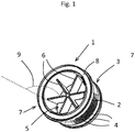
- the connecting piece once has a cylindrical base body 2, which has a plurality of grooves 4 on its outer circumferential surface 3.
- the grooves 4 serve to make the attachment of further, not shown here, fluid lines on the connecting piece safer.
- In its inner passage opening 5 has connecting piece 1 radially outwardly facing, quasi star-shaped support ribs 6.
- the support ribs 6 serve to stiffen the base body 2.
- At its first axial end 7, the connection piece 1 has a weld-on surface 8, which is arranged circumferentially around the first end 7 and is aligned axially flat.
- the support ribs 6 have an angle of attack 9 of 90 °.
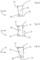
- Fig. 2a shows a support rib 10 as a schematic representation, which has in the flow direction 11 of a fluid flow, not shown, a flow angle 9a, which is greater than 90 °.
- the fluid flow or the flow direction of the fluid flow is symbolized here by the arrow 11, of the support sleeve 1 itself is here only a section shown in principle.
- the angle of incidence 9a is constant from an imaginary central axis 12 of the not shown flow to the radial end 13 of the support rib 10.
- a support rib 14 which has different flow angles 9b and 9c over the radial extent of the rib 14.
- the first angle of attack 9b is greater than 90 °, up to a predetermined radial distance 15 from the imaginary central axis 12 of the flow, not shown, the second angle of attack 9c is less than 90 °.
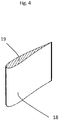
- a support rib 18 is shown in a partial longitudinal section.
- the support rib 18 has a wing-like contour 19, with which it is possible to influence the flow velocity of the flowing fluid to the support ribs 18 targeted.
- a support sleeve 1 is shown in principle in cross section, the support ribs 20 are distributed unevenly over the circumference of the flow cross section 21 of the support sleeve 1.
- the flow conditions in the support sleeve 1 can be influenced differently via their flow cross-section 21.
Landscapes
- Engineering & Computer Science (AREA)
- General Engineering & Computer Science (AREA)
- Mechanical Engineering (AREA)
- Chemical & Material Sciences (AREA)
- Combustion & Propulsion (AREA)
- Injection Moulding Of Plastics Or The Like (AREA)
Applications Claiming Priority (1)
| Application Number | Priority Date | Filing Date | Title |
|---|---|---|---|
| DE102017208439.1A DE102017208439A1 (de) | 2017-05-18 | 2017-05-18 | Verbindungsanordnung für Fluidleitungen |
Publications (1)
| Publication Number | Publication Date |
|---|---|
| EP3404249A1 true EP3404249A1 (fr) | 2018-11-21 |
Family
ID=61249536
Family Applications (1)
| Application Number | Title | Priority Date | Filing Date |
|---|---|---|---|
| EP18157530.9A Withdrawn EP3404249A1 (fr) | 2017-05-18 | 2018-02-20 | Dispositif de raccordement pour conduits fluidiques |
Country Status (2)
| Country | Link |
|---|---|
| EP (1) | EP3404249A1 (fr) |
| DE (1) | DE102017208439A1 (fr) |
Cited By (1)
| Publication number | Priority date | Publication date | Assignee | Title |
|---|---|---|---|---|
| EP3770416A1 (fr) * | 2019-07-24 | 2021-01-27 | ContiTech MGW GmbH | Dispositif de raccordement pour conduites fluidiques |
Citations (6)
| Publication number | Priority date | Publication date | Assignee | Title |
|---|---|---|---|---|
| EP0212883A2 (fr) * | 1985-08-02 | 1987-03-04 | John Derek Guest | Raccords de tubes |
| EP0333949A1 (fr) * | 1988-03-25 | 1989-09-27 | John Derek Guest | Raccord de tuyaux |
| US5685345A (en) * | 1995-12-21 | 1997-11-11 | Donaldson Company, Inc. | Reinforcing structure for conduit; and method |
| DE10305263A1 (de) * | 2002-02-07 | 2003-08-28 | Visteon Global Tech Inc | Lufteinlasssysteme und insbesondere auf ein Zurückhaltemittel bzw. eine Falle für Kohlenwasserstoffe |
| US20060278192A1 (en) * | 2005-05-23 | 2006-12-14 | Leo Now | Air horn for efficient fluid intake |
| DE102006050479B3 (de) * | 2006-10-20 | 2008-03-06 | Huang, Ching-Tung, Sinying | Anordnung zur Leistungserhöhung eines Kraftwagens in einer Luftleitung zwischen einem Leerlaufdrehzahlmotor und einer Drossel / einem Luftfilter |
-
2017
- 2017-05-18 DE DE102017208439.1A patent/DE102017208439A1/de not_active Withdrawn
-
2018
- 2018-02-20 EP EP18157530.9A patent/EP3404249A1/fr not_active Withdrawn
Patent Citations (6)
| Publication number | Priority date | Publication date | Assignee | Title |
|---|---|---|---|---|
| EP0212883A2 (fr) * | 1985-08-02 | 1987-03-04 | John Derek Guest | Raccords de tubes |
| EP0333949A1 (fr) * | 1988-03-25 | 1989-09-27 | John Derek Guest | Raccord de tuyaux |
| US5685345A (en) * | 1995-12-21 | 1997-11-11 | Donaldson Company, Inc. | Reinforcing structure for conduit; and method |
| DE10305263A1 (de) * | 2002-02-07 | 2003-08-28 | Visteon Global Tech Inc | Lufteinlasssysteme und insbesondere auf ein Zurückhaltemittel bzw. eine Falle für Kohlenwasserstoffe |
| US20060278192A1 (en) * | 2005-05-23 | 2006-12-14 | Leo Now | Air horn for efficient fluid intake |
| DE102006050479B3 (de) * | 2006-10-20 | 2008-03-06 | Huang, Ching-Tung, Sinying | Anordnung zur Leistungserhöhung eines Kraftwagens in einer Luftleitung zwischen einem Leerlaufdrehzahlmotor und einer Drossel / einem Luftfilter |
Cited By (1)
| Publication number | Priority date | Publication date | Assignee | Title |
|---|---|---|---|---|
| EP3770416A1 (fr) * | 2019-07-24 | 2021-01-27 | ContiTech MGW GmbH | Dispositif de raccordement pour conduites fluidiques |
Also Published As
| Publication number | Publication date |
|---|---|
| DE102017208439A1 (de) | 2018-11-22 |
Similar Documents
| Publication | Publication Date | Title |
|---|---|---|
| AT401417B (de) | Schiebehülsen-verbindung für kunststoffrohre | |
| EP2616658B2 (fr) | Conduite de fluide présentant un résonateur | |
| EP1835144A2 (fr) | Branchement pour élément d'arrivée d'air en forme de tuyau sur une turbocompresseur | |
| EP2330326B1 (fr) | Composant tubulaire | |
| DE2025416A1 (de) | Rohrkupplung | |
| DE3443943A1 (de) | Rohrverbindung | |
| DE102007045043A1 (de) | Dichtring | |
| EP3022430B1 (fr) | Tube de support, élément filtre et système de filtration pourvu d'un tube de support, ainsi que procédé et dispositif permettant de produire le tube support | |
| EP3404305A1 (fr) | Dispositif de raccordement pour conduits fluidiques | |
| EP3404249A1 (fr) | Dispositif de raccordement pour conduits fluidiques | |
| EP2083191B1 (fr) | Palier | |
| DE19814650A1 (de) | Verfahren zur Herstellung einer Drosselstelle | |
| EP2304305B1 (fr) | Raccord réducteur de tube en un matériau plastique | |
| EP3404304A1 (fr) | Dispositif de raccordement pour conduits fluidiques | |
| DE102012112852A1 (de) | Rohrbogen zur Abgasführung in Heizungsanlagen und Anordnung mit einem Rohrbogen | |
| DE102020119002B3 (de) | Rohrmuffe | |
| DE102017119201A1 (de) | Steckverbinder und Rohrverbindung mit einem Steckverbinder | |
| DE2223417A1 (de) | Schraubverbindung mit dichtungsring | |
| DE19536300C1 (de) | Wärmetauscher | |
| EP3130709B1 (fr) | Corps de base de cage en plastique pour une cage de revision ou d'inspection | |
| EP3770416B1 (fr) | Dispositif de raccordement pour conduites fluidiques | |
| DE112018007857T5 (de) | Filtersatz, Montagesystem des Filtersatzes und Baugruppe der Flüssigkeitszuleitung | |
| EP4071393B1 (fr) | Agencement de conduite | |
| DE202008006653U1 (de) | Steckbare Rohrverbindung | |
| DE102018125199B4 (de) | Mehrteiliges Buchsenlager |
Legal Events
| Date | Code | Title | Description |
|---|---|---|---|
| PUAI | Public reference made under article 153(3) epc to a published international application that has entered the european phase |
Free format text: ORIGINAL CODE: 0009012 |
|
| AK | Designated contracting states |
Kind code of ref document: A1 Designated state(s): AL AT BE BG CH CY CZ DE DK EE ES FI FR GB GR HR HU IE IS IT LI LT LU LV MC MK MT NL NO PL PT RO RS SE SI SK SM TR |
|
| AX | Request for extension of the european patent |
Extension state: BA ME |
|
| 17P | Request for examination filed |
Effective date: 20190521 |
|
| RBV | Designated contracting states (corrected) |
Designated state(s): AL AT BE BG CH CY CZ DE DK EE ES FI FR GB GR HR HU IE IS IT LI LT LU LV MC MK MT NL NO PL PT RO RS SE SI SK SM TR |
|
| 17Q | First examination report despatched |
Effective date: 20200224 |
|
| STAA | Information on the status of an ep patent application or granted ep patent |
Free format text: STATUS: THE APPLICATION IS DEEMED TO BE WITHDRAWN |
|
| 18D | Application deemed to be withdrawn |
Effective date: 20200707 |