EP3022836B1 - Protection contre les surtensions pour redresseurs actifs en cas de délestage brusque - Google Patents
Protection contre les surtensions pour redresseurs actifs en cas de délestage brusque Download PDFInfo
- Publication number
- EP3022836B1 EP3022836B1 EP14732204.4A EP14732204A EP3022836B1 EP 3022836 B1 EP3022836 B1 EP 3022836B1 EP 14732204 A EP14732204 A EP 14732204A EP 3022836 B1 EP3022836 B1 EP 3022836B1
- Authority
- EP
- European Patent Office
- Prior art keywords
- threshold value
- voltage
- output voltage
- bridge rectifier
- upper threshold
- Prior art date
- Legal status (The legal status is an assumption and is not a legal conclusion. Google has not performed a legal analysis and makes no representation as to the accuracy of the status listed.)
- Not-in-force
Links
- 238000000034 method Methods 0.000 claims description 8
- 230000000694 effects Effects 0.000 claims description 7
- 230000008859 change Effects 0.000 claims description 5
- 230000007423 decrease Effects 0.000 claims description 5
- 238000004590 computer program Methods 0.000 claims description 2
- 238000010586 diagram Methods 0.000 description 6
- 238000011017 operating method Methods 0.000 description 5
- 238000001514 detection method Methods 0.000 description 4
- 238000011156 evaluation Methods 0.000 description 4
- 230000006399 behavior Effects 0.000 description 3
- 230000006378 damage Effects 0.000 description 3
- 238000004804 winding Methods 0.000 description 3
- 230000004913 activation Effects 0.000 description 2
- 239000003990 capacitor Substances 0.000 description 2
- 230000005669 field effect Effects 0.000 description 2
- 230000006870 function Effects 0.000 description 2
- 230000000977 initiatory effect Effects 0.000 description 2
- WNEODWDFDXWOLU-QHCPKHFHSA-N 3-[3-(hydroxymethyl)-4-[1-methyl-5-[[5-[(2s)-2-methyl-4-(oxetan-3-yl)piperazin-1-yl]pyridin-2-yl]amino]-6-oxopyridin-3-yl]pyridin-2-yl]-7,7-dimethyl-1,2,6,8-tetrahydrocyclopenta[3,4]pyrrolo[3,5-b]pyrazin-4-one Chemical compound C([C@@H](N(CC1)C=2C=NC(NC=3C(N(C)C=C(C=3)C=3C(=C(N4C(C5=CC=6CC(C)(C)CC=6N5CC4)=O)N=CC=3)CO)=O)=CC=2)C)N1C1COC1 WNEODWDFDXWOLU-QHCPKHFHSA-N 0.000 description 1
- 230000033228 biological regulation Effects 0.000 description 1
- 239000000969 carrier Substances 0.000 description 1
- 230000003247 decreasing effect Effects 0.000 description 1
- 230000005611 electricity Effects 0.000 description 1
- 230000005284 excitation Effects 0.000 description 1
- 238000002955 isolation Methods 0.000 description 1
- 230000015654 memory Effects 0.000 description 1
- 230000008569 process Effects 0.000 description 1
- 230000007704 transition Effects 0.000 description 1
Images


Classifications
-
- H—ELECTRICITY
- H02—GENERATION; CONVERSION OR DISTRIBUTION OF ELECTRIC POWER
- H02H—EMERGENCY PROTECTIVE CIRCUIT ARRANGEMENTS
- H02H7/00—Emergency protective circuit arrangements specially adapted for specific types of electric machines or apparatus or for sectionalised protection of cable or line systems, and effecting automatic switching in the event of an undesired change from normal working conditions
- H02H7/10—Emergency protective circuit arrangements specially adapted for specific types of electric machines or apparatus or for sectionalised protection of cable or line systems, and effecting automatic switching in the event of an undesired change from normal working conditions for converters; for rectifiers
- H02H7/12—Emergency protective circuit arrangements specially adapted for specific types of electric machines or apparatus or for sectionalised protection of cable or line systems, and effecting automatic switching in the event of an undesired change from normal working conditions for converters; for rectifiers for static converters or rectifiers
- H02H7/125—Emergency protective circuit arrangements specially adapted for specific types of electric machines or apparatus or for sectionalised protection of cable or line systems, and effecting automatic switching in the event of an undesired change from normal working conditions for converters; for rectifiers for static converters or rectifiers for rectifiers
- H02H7/1252—Emergency protective circuit arrangements specially adapted for specific types of electric machines or apparatus or for sectionalised protection of cable or line systems, and effecting automatic switching in the event of an undesired change from normal working conditions for converters; for rectifiers for static converters or rectifiers for rectifiers responsive to overvoltage in input or output, e.g. by load dump
-
- B—PERFORMING OPERATIONS; TRANSPORTING
- B60—VEHICLES IN GENERAL
- B60L—PROPULSION OF ELECTRICALLY-PROPELLED VEHICLES; SUPPLYING ELECTRIC POWER FOR AUXILIARY EQUIPMENT OF ELECTRICALLY-PROPELLED VEHICLES; ELECTRODYNAMIC BRAKE SYSTEMS FOR VEHICLES IN GENERAL; MAGNETIC SUSPENSION OR LEVITATION FOR VEHICLES; MONITORING OPERATING VARIABLES OF ELECTRICALLY-PROPELLED VEHICLES; ELECTRIC SAFETY DEVICES FOR ELECTRICALLY-PROPELLED VEHICLES
- B60L50/00—Electric propulsion with power supplied within the vehicle
- B60L50/10—Electric propulsion with power supplied within the vehicle using propulsion power supplied by engine-driven generators, e.g. generators driven by combustion engines
-
- H—ELECTRICITY
- H02—GENERATION; CONVERSION OR DISTRIBUTION OF ELECTRIC POWER
- H02M—APPARATUS FOR CONVERSION BETWEEN AC AND AC, BETWEEN AC AND DC, OR BETWEEN DC AND DC, AND FOR USE WITH MAINS OR SIMILAR POWER SUPPLY SYSTEMS; CONVERSION OF DC OR AC INPUT POWER INTO SURGE OUTPUT POWER; CONTROL OR REGULATION THEREOF
- H02M1/00—Details of apparatus for conversion
- H02M1/32—Means for protecting converters other than automatic disconnection
-
- H—ELECTRICITY
- H02—GENERATION; CONVERSION OR DISTRIBUTION OF ELECTRIC POWER
- H02M—APPARATUS FOR CONVERSION BETWEEN AC AND AC, BETWEEN AC AND DC, OR BETWEEN DC AND DC, AND FOR USE WITH MAINS OR SIMILAR POWER SUPPLY SYSTEMS; CONVERSION OF DC OR AC INPUT POWER INTO SURGE OUTPUT POWER; CONTROL OR REGULATION THEREOF
- H02M7/00—Conversion of AC power input into DC power output; Conversion of DC power input into AC power output
- H02M7/02—Conversion of AC power input into DC power output without possibility of reversal
- H02M7/04—Conversion of AC power input into DC power output without possibility of reversal by static converters
- H02M7/12—Conversion of AC power input into DC power output without possibility of reversal by static converters using discharge tubes with control electrode or semiconductor devices with control electrode
- H02M7/21—Conversion of AC power input into DC power output without possibility of reversal by static converters using discharge tubes with control electrode or semiconductor devices with control electrode using devices of a triode or transistor type requiring continuous application of a control signal
- H02M7/217—Conversion of AC power input into DC power output without possibility of reversal by static converters using discharge tubes with control electrode or semiconductor devices with control electrode using devices of a triode or transistor type requiring continuous application of a control signal using semiconductor devices only
- H02M7/219—Conversion of AC power input into DC power output without possibility of reversal by static converters using discharge tubes with control electrode or semiconductor devices with control electrode using devices of a triode or transistor type requiring continuous application of a control signal using semiconductor devices only in a bridge configuration
-
- Y—GENERAL TAGGING OF NEW TECHNOLOGICAL DEVELOPMENTS; GENERAL TAGGING OF CROSS-SECTIONAL TECHNOLOGIES SPANNING OVER SEVERAL SECTIONS OF THE IPC; TECHNICAL SUBJECTS COVERED BY FORMER USPC CROSS-REFERENCE ART COLLECTIONS [XRACs] AND DIGESTS
- Y02—TECHNOLOGIES OR APPLICATIONS FOR MITIGATION OR ADAPTATION AGAINST CLIMATE CHANGE
- Y02B—CLIMATE CHANGE MITIGATION TECHNOLOGIES RELATED TO BUILDINGS, e.g. HOUSING, HOUSE APPLIANCES OR RELATED END-USER APPLICATIONS
- Y02B70/00—Technologies for an efficient end-user side electric power management and consumption
- Y02B70/10—Technologies improving the efficiency by using switched-mode power supplies [SMPS], i.e. efficient power electronics conversion e.g. power factor correction or reduction of losses in power supplies or efficient standby modes
Definitions
- the present invention relates to an active bridge rectifier with means for protection against overvoltage during load shedding, a motor vehicle electrical system with such a bridge rectifier, an associated operating method and means for implementing this operating method.
- rectifiers of different types can be used.
- bridge rectifiers in a six-pulse design are frequently used in correspondence with the three-phase generators usually installed there.
- the invention is equally applicable to bridge rectifiers for other phase numbers, e.g. for five-phase generators.
- a critical fault with bridge rectifiers is load dumping. This occurs when the load on the generator or the associated bridge rectifier (eg by switching off consumers) abruptly decreases when the generator is highly energized and the output current is high, and this is not caused by capacitive elements in the direct voltage network (eg the battery in the Motor vehicle electrical system) can be intercepted. In this case could be supplied by the generator or the associated bridge rectifier in extreme cases, up to a duration of about 300 to 500 ms more energy into the vehicle electrical system. This must be able to be intercepted in the bridge rectifier to protect electrical components in the motor vehicle electrical system from overvoltage damage. This is done at passive bridge rectifiers usually by the built-there rectifier diodes, in which the excess energy can be converted into heat.
- the generator phases can be briefly short-circuited by Leitendvul all switching elements of the upper or lower rectifier branch, such as in the DE 198 35 316 A1 revealed and in the DE 10 2009 046 955 A1 discussed. This is done in particular on the basis of an evaluation of the voltage applied to the DC voltage terminals of the active bridge rectifier output voltage. If this exceeds a predetermined upper threshold value, a corresponding short circuit is initiated and the output voltage drops. If the output voltage falls below a predetermined lower threshold, the short circuit is canceled again. The output voltage rises again. This is a typical hysteresis behavior. The output voltage therefore essentially shifts between the upper and lower threshold values during load shedding until the voltage regulation has adapted to the new situation and the excitation field of the generator has been correspondingly reduced.
- the present invention proposes an active bridge rectifier with means for protection against overloads during load shedding, a motor vehicle electrical system with such a bridge rectifier, an associated operating method and means for implementing this method of operation with the features of the independent claims.
- the present invention relates to the operation of an active bridge rectifier during load shedding.
- an operation may include, the generator phases or the corresponding AC voltage terminals of the active bridge rectifier when an upper threshold is exceeded by simultaneously driving (and thus simultaneous Leitend terminate) all controllable or active switching elements of a rectifier branch conductively connected to each other (short-circuit) and corresponding short circuits fall below a lower threshold simultaneously cancel.
- decentralized active bridge rectifiers in which the individual half bridges each have independent drive circuits, each individually detect the voltage applied to the DC voltage terminals of the active bridge rectifier output voltage, such operation is sought, in the prior art, however, due to the above-explained tolerances not always achieved in the voltage detection and / or downstream elements of the drive circuits.
- the measures according to the invention make such operation possible in a particularly advantageous manner.
- the threshold values for example due to deviations between the comparison circuits, are different.
- the case is particularly critical when the lower thresholds are different. Because the drive circuits of all other half bridges resume normal operation before the drive circuit with the effectively lowest lower threshold, the output voltage rises again. It may therefore happen that the drive circuit with the effectively lowest lower threshold never detects an output voltage below this effectively lowest lower threshold.
- the correspondingly controlled switching element thus remains permanently conductive.
- An active bridge rectifier has, as is generally known, half-bridges which define with their respective switching elements an upper and a lower or highside and low side rectifier branch.
- the switching elements arranged in the upper or high-side rectifier branch in each case a connection of one or more AC voltage connections to a positive DC voltage connection and a connection of one or more AC voltage connections to a negative DC voltage connection can be established by means of the switching elements arranged in the lower or Lowside rectifier branch.
- Each half-bridge therefore has two switching elements which are connected in series and can be driven in series between the two direct-voltage terminals and between which one of the alternating-voltage terminals is connected in each case.
- the active bridge rectifier is connected to a corresponding number of generator phases, and the DC voltage connections supply a DC electrical system.
- the negative DC voltage connection can in particular be grounded.
- the rectifying operation of the active bridge rectifier an output voltage, which can correspond to the vehicle electrical system voltage of a connected electrical system.
- corresponding active bridge rectifiers can also be operated in an alternating manner, for example in hybrid vehicles for commutating an electric motor. Such operating phases are not considered here. However, it is understood that if in the context of this application of a generator is mentioned, this can also be a both generator and motor operable electric machine. The same applies to the active rectifier, which can also be operated in an alternating manner in corresponding operating phases for commutation.
- each half-bridge comprises a drive circuit which is set up to detect an output voltage applied between the two DC voltage terminals.
- This is further configured to switch a first switching element of the two switching elements of the respective half-bridge by triggering with a first drive signal until the output voltage falls below a lower threshold after it has previously exceeded an upper threshold, and this by driving with a second drive signal clocked to drive until the output voltage exceeds the upper threshold after it has previously fallen below the lower threshold.
- the first switching element is the switching element which is provided for the initiation or cancellation of a corresponding phase short circuit.
- the respective other switching element is referred to as a second switching element in the context of this application.
- the invention will be described below mainly with reference to the activation of a first switching element in the lower or low-side rectifier branch described with the first drive signal, but can be used in the same way for driving a corresponding first switching element in an upper or high-side rectifier branch.
- the first drive signal is thus used when a load shedding is detected. This detection is performed by a threshold value comparison in the drive circuit.
- the first drive signal is preferably a continuous signal which causes the first switching element to be permanently put into a conductive state, ie produces a conductive connection between the respective AC voltage connection connected to the half bridge and one of the two DC voltage connections, as long as a corresponding one first drive signal is present.
- the second drive signal is, in particular, a drive signal which is used to drive a corresponding bridge rectifier in normal rectifier operation.
- This drive signal is thus clocked by pulse width modulation.
- it can also be provided by a superordinated control unit, with the respective control circuit being set up to forward the control signal provided by the superordinate control unit to the respective first switching element.
- each drive circuit is provided with threshold means adapted to effect a change of the lower and / or upper threshold after the output voltage has previously exceeded or exceeded the upper threshold.
- the threshold means may be configured as analog or digital threshold means.
- the invention makes it possible to effect a change in the lower and / or upper threshold value in such cases.
- the lower threshold successively (ie, for example, gradually or continuously) to raise. This can be done, for example, by means of a circuit as described below with reference to FIGS FIG. 7 is explained done.
- this upper threshold value can be set higher. If a crossing of the upper threshold value is detected again within a predetermined time window (filter time), it can be increased again, for example by an increment, and otherwise reduced accordingly. In the steady state, the upper thresholds increase and decrease alternately. The respective switching elements are thus alternately turned on and not turned on.
- the effective upper threshold values are therefore in a narrow range in all phases, which is predetermined, for example, by the size of the incremental value for the upper threshold value.
- the measures just explained also relate to measures relating to the lower threshold value, which can be increased or decreased in particular synchronously with the upper threshold value.
- a particularly advantageous embodiment of the method according to the invention comprises the use of dead times in the phase-specific drive circuits.
- a dead time causes the respective drive circuit does not immediately output the drive signal to the switching element provided for this purpose, if it detects a corresponding event, but only after elapse of a predetermined time window.
- a corresponding dead time can thereby be implemented both on detection of exceeding the upper threshold and falling below the lower threshold. If, for example, the output voltage increases, the drive circuit with the (effectively) lowest upper threshold value first detects that this threshold value is exceeded. However, it switches the switching element provided for this purpose not immediately conductive, but "waits" initially the lapse of the dead time.
- the output voltage therefore continues to rise during the dead time until the switching elements with the (effectively) higher upper threshold values (in which a corresponding dead time is likewise implemented) also detect a threshold value overshoot.
- a wiring of all switching elements is ensured.
- the switching element with the (effectively) highest lower threshold value recognizes this first when the output voltage drops. Again, it does not control the switching element provided for this purpose immediately, but "waits" first, the lapse of the dead time.
- the output voltage therefore continues to drop during the dead time until the switching elements with the (effectively) lower lower threshold values (in which a corresponding dead time is likewise implemented) also detect a threshold undershoot.
- the dead time can be implemented by circuitry, for example by means of an RC element at the output of a comparator used or by means of a digital counter. It should be chosen such that the individual differences (tolerances) in the phase-specific drive circuits are reliably compensated, but the output voltage does not assume critically high or low values.
- An arithmetic unit according to the invention for example a control unit of a motor vehicle or a rectifier control, is, in particular programmatically, configured to carry out a method according to the invention.
- Suitable data carriers for providing the computer program are, in particular, floppy disks, hard disks, flash memories, EEPROMs, CD-ROMs, DVDs and the like. It is also possible to download a program via computer networks (Internet, intranet, etc.).
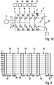
- FIGS. 1A to 1C show arrangements with active bridge rectifiers and their function in a schematic representation.
- FIG 1A an arrangement with an active bridge rectifier 1 and a generator 2 is shown schematically using the example of a three-phase system.
- the active bridge rectifier 1 is in Figure 1A shown as a six-pulse active bridge rectifier 1, which is set up to rectify a three-phase current of a three-phase generator 2.
- a four-, five-, six- or seven-phase generator 2 and a correspondingly adapted active bridge rectifier 1 can be used.
- the Figures 1B and 1C For example, show an arrangement with a five-phase generator 2 and a corresponding active bridge rectifier. 1
- the active bridge rectifier 1 has three half bridges U, V and W, which are connected via AC voltage terminals u, v and w of the active bridge rectifier 1 with corresponding outputs of the generator 2, and thus with the respective generator windings.
- the half bridges U, V and W are the output side, ie via corresponding DC voltage terminals B + and B- of the active bridge rectifier 1, for example, to a positive battery terminal (B +) and a negative battery terminal (B-) and / or corresponding supply lines of a DC network connected.
- the DC voltage connection B- can be connected to ground.
- the half-bridges U, V and W each have controllable or active switching elements S1 to S6, which are each bound into an upper branch H (highside) and a lower branch L (low-side) of the respective half-bridges U, V, and W.
- One of the AC voltage terminals u, v and w can be connected to B + and / or B according to a corresponding wiring of the switching elements S1 to S6, wherein a simultaneous control of both switching elements of a half-bridge U, V and W (ie S1 / S4, S2 / S5 and S3 / S6) in control mode to avoid so-called hot paths between the two DC voltage terminals B + and B-.
- a control unit 3 may be provided for controlling the active bridge rectifier 1, a control unit 3 may be provided.
- individual drive circuits designated here by 4U to 4W, take on at least part of the required switching tasks of the respective half bridges U, V and W.
- the switching elements S1 to S6 can have their respective gate terminals G via dotted lines g are applied by means of the individual drive circuits 4U to 4W according to a drive pattern with a drive signal.
- the control pattern can be predefined by the control unit 3, for example.
- the switching elements of a half-bridge U, V and W are controlled in normal operation of the illustrated arrangement such that a voltage applied to a corresponding AC voltage terminal u, v and w current signal of a generator winding connected thereto Generator 2 alternately to one of the two DC voltage terminals B + and B-controlled by.
- This is usually done in such a way that when a positive half-wave is applied to the AC voltage terminals u, v and w, the respective signal to the DC voltage terminal B +, while applying a negative half-wave, the signal to the DC voltage terminal B-controlled becomes.
- the setting of an output voltage at the DC voltage terminal B + can also be done by a corresponding timing.
- a load shedding can be done in an in Figure 1A shown arrangement based on a voltage applied between the DC voltage terminals B + and B- voltage can be detected.
- the individual driving circuits 4U to 4W are arranged as described below with reference to FIGS FIG. 4A illustrated.
- the individual drive circuits 4U to 4W are connected via lines b to at least one DC-side output of the active bridge rectifier 1, in this case to the output connected to B +. If a defined threshold value of the voltage applied to this DC side output of the active bridge rectifier 1 voltage is exceeded, a load shedding can be detected.
- the individual drive circuits 4U to 4W for voltage detection can furthermore be connected to a reference potential, for example the other DC voltage connection or ground.
- the activation of the active bridge rectifier 1 in the case of a detected load shedding can be effected in such a way that the phase windings of the generator 2, which are each connected to the half bridges U, V and W of the active bridge rectifier 1 via one of the alternating voltage terminals u, v and w, are short-circuited in a time-defined manner become.
- the current fed into the electrical system drops to zero.
- a corresponding short circuit can be produced by a simultaneous driving and thus Leitendvul the switching elements S1 to S3 or S4 to S6 each of a rectifier branch H and L respectively. If the short circuit is released, the current increases again.
- This process can be used in a transition phase to control the output voltage of the generator 2 until the normal control via the generator controller takes effect again. As mentioned, however, this does not occur reliably when using the individual evaluation circuits 4U to 4W according to the prior art. The resulting negative effects are described below with reference to FIGS Figures 3 and 5 illustrated. A solution according to an embodiment of the invention in the form of a customized individual evaluation circuit 4U is described below with reference to FIGS FIG. 7 illustrated.
- FIGS 1B and 1C In each case arrangements are shown with a five-phase generator 2 and an active bridge rectifier 1 with five half-bridges.
- the inputs are labeled u to y, the half bridges corresponding to U to Y and the individual drive circuits 4U to 4X.
- On a representation of the lines b and g has been omitted for clarity.
- the half bridges U to Y each have switching elements S1 to S10.
- the switching elements S1 to S10 are illustrated as switches with parallel-connected diode, but in reality, for example, as MOS field-effect transistors as in Figure 1A educated. For the rest, the arrangements correspond to Figures 1B and 1C those of Figure 1A ,
- a vehicle electrical system capacitance C1 and a resistive load R1 are arranged in a downstream vehicle electrical system 4.
- the resistive load corresponds, for example, to a consumer in the electrical system 4.
- the lines in the vehicle electrical system 4 result in a line inductance L1.
- FIG. 1B is an instantaneous state of normal operation of the corresponding arrangement shown. It is assumed here that, at this time, a current flows from the generator into the active bridge rectifier through the AC voltage terminals u and v, while a current flows from the active bridge rectifier into the generator through the AC voltage terminals w, x, and y.
- the switching elements S1 and S2 establish by a corresponding control a conductive connection of the AC voltage terminals u and v with the DC voltage terminal B + forth.
- the switching elements S8, S9 and S10 make a conductive connection of the AC voltage terminals w, x and y to the DC voltage terminal B- forth.
- a vehicle electrical system capacitance C1 is provided in the present case, a part of the current, for example 130 A, flows into this and charges it. The remaining portion, here 20 A, flows into the actual vehicle electrical system 4 or the resistive load R1.
- a switching state can be set periodically, as in Figure 1C is shown.
- all switching elements S6 to S10 of the lower rectifier branch L are turned on.
- the AC voltage connections u to y and thus the corresponding generator phases are thereby conductively connected to one another (short-circuited).
- the electrical system 4 is fed in this switching state exclusively from the electrical system capacity C1.
- the switching state of Figure 1C is adjusted until a voltage between the DC voltage terminals B + and B- is again below a permissible value.
- the switching state of the FIG. 1B adjusted until the voltage between the DC voltage terminals B + and B- again exceeds the allowable value, etc.
- FIG. 2 is a generator current waveform in such a control of an active bridge rectifier 1 during load shedding according to the prior art shown.
- the generator current waveform is plotted as current I in A on the y-axis against a time t in ms on the x-axis.
- the switching elements S1 to S3 or S4 to S6 (or the switching elements S1 to S5 or S6 to S10 according to FIGS Figures 1B and 1C ) in each case a rectifier branch H or L during certain periods 21 simultaneously driven, and the AC voltage terminals thus short-circuited.
- no electricity is delivered to the electrical system 4.
- the short circuit is released and a current as in regular rectifier operation in the electrical system 4 delivered.
- FIG. 3 is a voltage waveform at the positive DC voltage terminal B + in a three-phase active bridge rectifier according to the prior art illustrated, the half-bridges, as with reference to the Figure 1A illustrated having individual drive circuits.
- the individual drive circuits or corresponding evaluation circuits react slightly differently in each phase, which results in correspondingly different threshold values for the phases U, V and W.
- these explanations also apply to a five-phase active bridge rectifier, as in the Figures 1B and 1C is illustrated.
- FIG. 3 are respectively upper threshold values of the individual drive circuits of the half bridges U to W (see drive circuits 4U to 4W of FIG Figure 1A ) of a corresponding rectifier is designated 30U to 30W, the lower thresholds corresponding to 31U to 31W. It can be seen that the upper and the lower threshold of the drive circuit of the half-bridge W, 30W and 31W, is well above the thresholds of the drive circuit of the half-bridge V, 30V and 31V, which in turn above the thresholds of the drive circuits of the half-bridge U, 30U and 31U, lies.
- a voltage curve 301 as applied, for example, to a DC voltage connection of such an active bridge rectifier, for example the DC voltage terminal B +, is plotted as the voltage value U in V on the ordinate with respect to a time t in s on the abscissa.
- the voltage value of the voltage curve 301 lies in a range which is normal for rectification and corresponds, for example, to a setpoint voltage for an electrical system, for example 12 V.
- the corresponding active bridge rectifier is therefore in regular rectifier operation.
- a time tLD is a load shedding, for example by switching off a consumer in the electrical system.
- the voltage value of the voltage curve 301 increases abruptly.
- the voltage value of the voltage curve 301 reaches the upper threshold value 30U of the drive circuit of the half-bridge U.
- the switching element of this half-bridge V provided for this purpose (see switching element S5 in FIG FIG. 1 ) is turned on.
- the voltage value of the voltage curve 310 decreases.
- the upper threshold value 30W of the drive circuit of the half bridge W, 30W is thus no longer reached, so that the corresponding switching element of this half bridge W (see switching element S6 in FIG. 1 ) in the regular control, eg a clocked control, which it also experiences between the times t0 and tLD remains.
- the voltage value of the voltage waveform 301 reaches the lower threshold value 31V of the drive circuit of the half-bridge V.
- the drive circuit of the half-bridge V now releases the permanently conductive state of the corresponding switching element and returns to regular driving, e.g. a clocked control, which also takes place between the times t0 and tLD, back, so that only the driven by the drive circuit of the half-bridge U switching element remains in the permanently conductive state.
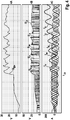
- FIG. 4 The resulting effects on the current and voltage characteristics of a corresponding active five-phase rectifier according to the prior art are in FIG. 4 illustrated.
- a voltage curve UB + at a DC side output of an active bridge rectifier, here B +, in V in a partial diagram 4B curves of the phase voltages Uu to Uy in V and in a partial diagram 4C corresponding to the phase currents lu to ly in A on the ordinate with respect to a common time axis t in s on the abscissa.
- the switching element actuated by the drive circuit of the half-bridge U can also return to the regular drive.
- FIG. The effects are shown in FIG. The representation corresponds to the FIG. 4 , None of the phase currents lu to ly reaches a critical value here, the switching elements are spared.
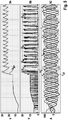
- FIG. 6 shows a drive circuit according to the prior art in a schematic representation.
- the drive circuit is designated as a whole with 4U 'and is used for example in an active bridge rectifier 1, as in the FIGS. 1A to 1C is shown.
- a corresponding drive circuit can be constructed identically for all phases U to W or Y.
- a hysteresis circuit A1 is connected to its inputs (+ and -) to the DC voltage terminals B + and B- (and ground) of the active bridge rectifier 1, respectively.
- the hysteresis circuit A1 can thus evaluate a voltage present between the DC voltage terminals B + and B- (or ground). If this exceeds an upper threshold value (corresponding to point 311 of the FIG. 3 ), is applied to the output of the hysteresis A1, a signal via which the active switching element S2 is set in the conducting state via a diode D1.
- the active switching element S2 is now controlled only by a signal of the control unit 3.
- the control unit 3 further has lines for evaluating the voltage applied between the DC voltage terminals B + and B- (or ground) and the phase voltage and a further drive line for driving the active switching element S1. In a normal rectifier operation, the control unit 3 controls the switching elements S1 and S2 in a clocked manner via the corresponding lines.
- FIG. 7 shows a drive circuit according to an embodiment of the invention in a schematic representation. This is denoted by 4U and has the essential components of the drive circuit 4U '(see. FIG. 6 ). Again, a corresponding drive circuit for all phases U to W or Y can be constructed identical.
- a hysteresis circuit A2 deviating from the drive circuit 4U 'is which has an RC element comprising a resistor R2 and a capacitor C2. If a signal is present at the output of the hysteresis circuit A2, the capacitor C2 is charged via the resistor R2.
- the hysteresis circuit A2 is set up by means of a line a for shifting its threshold values upward by applying a voltage to this line. This is done successively by the RC element from the point in time at which the upper threshold value at the hysteresis circuit A2 is exceeded. As a result, the lower threshold value of the hysteresis circuit A2 is continuously increased.
Landscapes
- Engineering & Computer Science (AREA)
- Power Engineering (AREA)
- Transportation (AREA)
- Mechanical Engineering (AREA)
- Rectifiers (AREA)
- Control Of Eletrric Generators (AREA)
Claims (11)
- Redresseur en pont (1), lequel possède une pluralité de bornes de tension alternative (u - y), deux bornes de tension continue (B+, B-) ainsi qu'une pluralité de demi-ponts (U - Y) correspondant à la pluralité de bornes de tension alternative (u - y),* chaque demi-pont (U - Y) possédant deux éléments de commutation (S1 - S10) branchés en série entre les deux bornes de tension continue (B+, B-) et commandables, entre lesquels est respectivement raccordée l'une des bornes de tension alternative (u - y), et* chaque demi-pont (U - Y) comprenant un circuit d'excitation (4U - 4Y) qui est conçu pour détecter une tension de sortie (301) appliquée entre les deux bornes de tension continue (B+, B-) et pour commuter un premier élément de commutation (S1 - S10) des deux éléments de commutation du demi-pont (U - Y) respectifcaractérisé en ce que- par excitation avec un premier signal d'excitation pour le rendre passant jusqu'à ce que la tension de sortie (301) devienne inférieure à une valeur de seuil basse (31U - 31W) après que celle-ci soit préalablement devenue supérieure à une valeur de seuil haute (30U - 30W), et- de manière cyclique par excitation avec un deuxième signal d'excitation jusqu'à ce que la tension de sortie (301) devienne supérieure à la valeur de seuil haute (30U - 30W) après que celle-ci soit préalablement devenue inférieure à la valeur de seuil basse (31U - 31W),
chaque circuit d'excitation (4U - 4Y) possède des moyens de valeur de seuil (A2) qui sont conçus pour provoquer une modification de la valeur de seuil basse et/ou haute (30U - 30W, 31U - 31W) de telle sorte que la tension de sortie peut atteindre la valeur de seuil après que la tension de sortie (301) soit préalablement devenue supérieure à la valeur de seuil haute (30U - 30W) . - Redresseur en pont (1) selon la revendication 1, les moyens de valeur de seuil (A2) étant conçus pour augmenter successivement la valeur de seuil basse (31U - 31W) à partir d'un instant auquel la tension de sortie (301) est devenue supérieure à la valeur de seuil haute (30U - 30W).
- Redresseur en pont (1) selon la revendication 2, les moyens de valeur de seuil (A2) comprenant un comparateur réalisé sous la forme d'un circuit à hystérésis, lequel possède une entrée de valeur de seuil qui est reliée à un réseau RC connecté à une sortie du comparateur.
- Redresseur en pont (1) selon la revendication 1, les moyens de valeur de seuil (A2) étant conçus pour toujours augmenter au moins la valeur de seuil haute (30U - 30W) lorsque la tension de sortie (301) devient supérieure à la valeur de seuil haute (30U - 30W) au moins deux fois au cours d'un créneau temporel prédéfini, et pour toujours la diminuer lorsque la tension de sortie (301) ne devient qu'une seule fois supérieure à la valeur de seuil haute (30U - 30W) au cours du créneau temporel prédéfini.
- Redresseur en pont (1) selon la revendication 4, les moyens de valeur de seuil (A2) étant conçus pour augmenter ou diminuer au moins la valeur de seuil haute (30U - 30W) d'un incrément prédéfini.
- Redresseur en pont (1) selon l'une des revendications précédentes, lequel comprend une unité de commande (3) qui est conçue pour délivrer le deuxième signal d'excitation au circuit d'excitation (4U - 4Y) et/ou aux éléments de commutation (S1 - S10) commandables.
- Réseau de bord de véhicule automobile (4) comprenant un redresseur en pont (1) selon l'une des revendications précédentes, les bornes de tension alternative (u - y) étant reliées à des bornes de phase d'un alternateur (2) et les deux bornes de tension continue (B+, B-) étant conçues pour alimenter au moins un consommateur (R1) dans le réseau de bord (4).
- Réseau de bord de véhicule automobile (4) selon la revendication 7, lequel possède en plus au moins un condensateur (C1) et/ou une inductance (L1) de réseau de bord.
- Procédé pour faire fonctionner un redresseur en pont (1) selon l'une des revendications 1 à 6 et/ou un réseau de bord de véhicule automobile (4) selon la revendication 7 ou 8, qui comprend, lors d'un délestage de charge, la commutation à l'état passant respectivement d'un premier élément de commutation (S1 - S10) des deux éléments de commutation (S1-S10) d'au moins deux demi-ponts (U - Y) par excitation au moyen d'un premier signal d'excitation jusqu'à ce que la tension de sortie (301) devienne inférieure à une valeur de seuil basse (31U - 31W) après que celle-ci soit préalablement devenue supérieure à une valeur de seuil haute (30U - 30W) et, l'excitation cyclique de celui-ci par excitation au moyen d'un deuxième signal d'excitation jusqu'à ce que la tension de sortie (301) devienne supérieure à la valeur de seuil haute (30U - 30W) après que celle-ci soit préalablement devenue inférieure à une valeur de seuil basse (31U - 31W), et une modification de la valeur de seuil basse et/ou haute (30U - 30W, 31U - 31W) du circuit d'excitation (4U - 4Y) correspondant étant respectivement effectuée après que la tension de sortie (301) soit préalablement devenue supérieure à la valeur de seuil haute (30U - 30W).
- Unité de commande (3) pour un redresseur en pont (1) selon l'une des revendications 1 à 6 ou un réseau de bord de véhicule automobile selon la revendication 7 ou 8, laquelle est conçue pour mettre en oeuvre un procédé selon la revendication 9.
- Programme informatique qui amène une unité de calcul, notamment une unité de commande (3) selon la revendication 10, à mettre en oeuvre un procédé selon la revendication 9 lorsqu'il est exécuté sur l'unité de calcul.
Applications Claiming Priority (2)
| Application Number | Priority Date | Filing Date | Title |
|---|---|---|---|
| DE102013213802.4A DE102013213802A1 (de) | 2013-07-15 | 2013-07-15 | Überspannungsschutz für aktive Gleichrichter bei Lastabwurf |
| PCT/EP2014/063230 WO2015007467A1 (fr) | 2013-07-15 | 2014-06-24 | Protection contre les surtensions pour redresseurs actifs en cas de délestage brusque |
Publications (2)
| Publication Number | Publication Date |
|---|---|
| EP3022836A1 EP3022836A1 (fr) | 2016-05-25 |
| EP3022836B1 true EP3022836B1 (fr) | 2017-06-07 |
Family
ID=50981530
Family Applications (1)
| Application Number | Title | Priority Date | Filing Date |
|---|---|---|---|
| EP14732204.4A Not-in-force EP3022836B1 (fr) | 2013-07-15 | 2014-06-24 | Protection contre les surtensions pour redresseurs actifs en cas de délestage brusque |
Country Status (6)
| Country | Link |
|---|---|
| US (1) | US9950626B2 (fr) |
| EP (1) | EP3022836B1 (fr) |
| JP (1) | JP6197110B2 (fr) |
| CN (1) | CN105359396B (fr) |
| DE (1) | DE102013213802A1 (fr) |
| WO (1) | WO2015007467A1 (fr) |
Families Citing this family (14)
| Publication number | Priority date | Publication date | Assignee | Title |
|---|---|---|---|---|
| DE102013208968B4 (de) * | 2013-05-15 | 2026-03-26 | Seg Automotive Germany Gmbh | Kraftfahrzeugbordnetz mit aktivem Brückengleichrichter und Überspannungsschutz bei Lastabwurf, Gleichrichteranordnung, zugehöriges Betriebsverfahren und Mittel zu dessen Implementierung |
| DE102013224106A1 (de) * | 2013-11-26 | 2015-05-28 | Robert Bosch Gmbh | Überspannungsschutz für Kraftfahrzeugbordnetz bei Lastabwurf |
| DE102014200503A1 (de) * | 2014-01-09 | 2015-07-09 | Robert Bosch Gmbh | Verfahren zum Betreiben eines aktiven Gleichrichters, Schaltungsanordnung und Computerprogramm |
| DE102015202437A1 (de) * | 2015-02-11 | 2016-08-11 | Robert Bosch Gmbh | Verfahren zum Betreiben eines an eine elektrische Maschine angeschlossenen aktiven Umrichters und Mittel zu dessen Implementierung |
| DE102015202440A1 (de) * | 2015-02-11 | 2016-08-11 | Robert Bosch Gmbh | Verfahren zum Betreiben eines an eine elektrische Maschine angeschlossenen aktiven Umrichters und Mittel zu dessen Implementierung |
| DE102017204159A1 (de) * | 2017-03-14 | 2018-09-20 | Robert Bosch Gmbh | Verfahren zum Erkennen eines Betriebsmodus eines Gleichrichters |
| DE102018202661A1 (de) | 2018-02-22 | 2019-08-22 | Zf Friedrichshafen Ag | Verfahren und Vorrichtung zum Entladen eines Zwischenkreiskondensators |
| DE102018203579A1 (de) | 2018-03-09 | 2019-09-12 | Zf Friedrichshafen Ag | Verfahren und Vorrichtung zum Betreiben eines Antriebssystems und Antriebssystem für ein Fahrzeug |
| CN110912426B (zh) * | 2018-09-18 | 2023-04-07 | 上海峰飞航空科技有限公司 | 整流电路和直流功率生成电路 |
| DE102018219398A1 (de) | 2018-11-14 | 2020-05-14 | Zf Friedrichshafen Ag | Verfahren und Vorrichtung zum Reduzieren einer Überspannung in einem mit einer Asynchronmaschine verbundenen Zwischenkreis bei einem Lastabwurf |
| DE102019124214A1 (de) * | 2019-09-10 | 2021-03-11 | Audi Ag | Verfahren zum Betrieb eines Kraftfahrzeugs mit einer permanenterregten Synchronmaschine und Kraftfahrzeug |
| US11929698B2 (en) * | 2021-03-23 | 2024-03-12 | Snap-On Incorporated | Short circuit protection for a BLDC motor |
| CN119160114B (zh) * | 2024-11-21 | 2025-06-06 | 南通康比电子有限公司 | 一种用于汽车整流器的电流预测控制方法 |
| TWI911002B (zh) * | 2025-01-03 | 2026-01-01 | 祥碩科技股份有限公司 | 整流電路及其操作方法 |
Family Cites Families (12)
| Publication number | Priority date | Publication date | Assignee | Title |
|---|---|---|---|---|
| DE3876953D1 (de) | 1987-11-20 | 1993-02-04 | Siemens Ag | Steuergeraet zur steuerung von funktionen eines kraftfahrzeuges bei einem load-dump. |
| JPH04178170A (ja) | 1990-11-08 | 1992-06-25 | Mitsubishi Electric Corp | 力率改善形整流装置 |
| JP3491797B2 (ja) | 1995-12-05 | 2004-01-26 | 株式会社デンソー | 車両用発電装置 |
| JPH10127062A (ja) | 1996-10-16 | 1998-05-15 | Hitachi Ltd | 電気車用インバータの保護回路 |
| DE19835316A1 (de) | 1998-08-05 | 2000-02-10 | Bosch Gmbh Robert | Gesteuerte Gleichrichterbrücke mit Überspannungsschutz |
| DE102009046952A1 (de) * | 2009-11-23 | 2011-05-26 | Robert Bosch Gmbh | Verfahren zur Regelung der Spannung in einem Bordnetz eines Kraftfahrzeugs |
| DE102009046955A1 (de) | 2009-11-23 | 2011-05-26 | Robert Bosch Gmbh | Vermeidung von Lastabwurf-Überspannungen bei Synchrongleichrichtern |
| DE102009055055A1 (de) | 2009-12-21 | 2011-06-22 | Robert Bosch GmbH, 70469 | Verfahren zur Fehlererkennung bei einer durch einen Wechselrichter angesteuerten elektrischen Maschine in einem Kraftfahrzeug und Vorrichtung zur Überwachung eines Betriebs der elektrischen Maschine |
| FR2962606B1 (fr) * | 2010-07-09 | 2020-09-25 | Denso Corp | Machine électrique tournante améliorée pour assurer une protection contre les coupures d'alimentation électrique |
| JP5408060B2 (ja) | 2010-07-09 | 2014-02-05 | 株式会社デンソー | 車両用発電機 |
| US8975886B2 (en) * | 2011-11-08 | 2015-03-10 | Texas Instruments Incorporated | Charging and distribution control |
| DE102011088973B4 (de) * | 2011-12-19 | 2024-08-08 | Seg Automotive Germany Gmbh | Verfahren und Vorrichtung zum Anpassen einer Spannungsgrenze in einem Bordnetz |
-
2013
- 2013-07-15 DE DE102013213802.4A patent/DE102013213802A1/de not_active Withdrawn
-
2014
- 2014-06-24 WO PCT/EP2014/063230 patent/WO2015007467A1/fr not_active Ceased
- 2014-06-24 EP EP14732204.4A patent/EP3022836B1/fr not_active Not-in-force
- 2014-06-24 JP JP2016520534A patent/JP6197110B2/ja not_active Expired - Fee Related
- 2014-06-24 US US14/905,244 patent/US9950626B2/en not_active Expired - Fee Related
- 2014-06-24 CN CN201480040100.5A patent/CN105359396B/zh not_active Expired - Fee Related
Also Published As
| Publication number | Publication date |
|---|---|
| JP6197110B2 (ja) | 2017-09-13 |
| WO2015007467A1 (fr) | 2015-01-22 |
| CN105359396A (zh) | 2016-02-24 |
| US9950626B2 (en) | 2018-04-24 |
| CN105359396B (zh) | 2018-07-10 |
| EP3022836A1 (fr) | 2016-05-25 |
| JP2016521963A (ja) | 2016-07-25 |
| US20160144724A1 (en) | 2016-05-26 |
| DE102013213802A1 (de) | 2015-01-15 |
Similar Documents
| Publication | Publication Date | Title |
|---|---|---|
| EP3022836B1 (fr) | Protection contre les surtensions pour redresseurs actifs en cas de délestage brusque | |
| DE102013106854B4 (de) | Schaltung zur Einschaltstrombegrenzung | |
| DE102013208968B4 (de) | Kraftfahrzeugbordnetz mit aktivem Brückengleichrichter und Überspannungsschutz bei Lastabwurf, Gleichrichteranordnung, zugehöriges Betriebsverfahren und Mittel zu dessen Implementierung | |
| EP3039761B1 (fr) | Protection contre la surtension pour redresseurs actifs en cas de suppression de charge | |
| EP2596980B1 (fr) | Convertisseur de courant à plusieurs points avec hacheur de freinage | |
| DE102015205633A1 (de) | Energieversorgungsgerät | |
| EP3075048B1 (fr) | Protection contre les surtensions pour réseau de bord de véhicule automobile en cas de délestage | |
| DE112017003632T5 (de) | Dc/dc-umrichter | |
| DE102013016960A1 (de) | Abschalten einer Wechselrichtereinheit und Betriebsverfahren | |
| EP2523334A1 (fr) | Convertisseur de fréquence et procédé de fonctionnement de celui-ci | |
| EP1508962B1 (fr) | Convertisseur avec liaison intermédiaire en tension | |
| EP3251194B1 (fr) | Ensemble d'accumulation d'énergie | |
| EP2893603B1 (fr) | Procédé de commande d'un redresseur en pont actif lors d'un délestage, système redresseur et produit logiciel informatique | |
| DE102019008340A1 (de) | Stromversorgung | |
| EP2784931A1 (fr) | Procédé et circuit de commande destinés à la commande d'un moteur électrique sans brosse | |
| EP3172827B1 (fr) | Procédé permettant de faire fonctionner un moteur électrique pouvant au moins fonctionner au moyen d'un générateur et moyens permettant la mise en oeuvre dudit procédé | |
| EP2648328B1 (fr) | Protection d'un convertisseur de courant avec circuit intermédiaire contre les dommages causés par la contre-tension d'une machine synchrone | |
| DE102022131772B4 (de) | Ansteueranordnung und Verfahren zum Betreiben einer elektrischen Maschine | |
| DE102017221635B4 (de) | Ermitteln einer Netzsystemart einer Energiequelle zum Aufladen eines elektrischen Energiespeichers | |
| EP3061186B1 (fr) | Demi-pont pour redresseur actif | |
| DE102015202912B3 (de) | Verfahren und Vorrichtung zum Ansteuern eines aktiven Brückengleichrichters bei Aufhebung eines Phasenkurzschlusses | |
| DE102016202169A1 (de) | Betreiben einer Anordnung aus generatorisch betriebener elektrischer Maschine und aktivem Brückengleichrichter | |
| EP3089340B1 (fr) | Élement d'un reseau de distribution destine a alimenter un convertisseur | |
| EP3172831A1 (fr) | Procédé de commande d'au moins une machine électrique pouvant fonctionner en générateur et moyen pour mettre en oeuvre celui-ci | |
| DE102012020578A1 (de) | Antriebsanordnung mit Energiespeicher |
Legal Events
| Date | Code | Title | Description |
|---|---|---|---|
| PUAI | Public reference made under article 153(3) epc to a published international application that has entered the european phase |
Free format text: ORIGINAL CODE: 0009012 |
|
| 17P | Request for examination filed |
Effective date: 20160215 |
|
| AK | Designated contracting states |
Kind code of ref document: A1 Designated state(s): AL AT BE BG CH CY CZ DE DK EE ES FI FR GB GR HR HU IE IS IT LI LT LU LV MC MK MT NL NO PL PT RO RS SE SI SK SM TR |
|
| AX | Request for extension of the european patent |
Extension state: BA ME |
|
| DAX | Request for extension of the european patent (deleted) | ||
| RIC1 | Information provided on ipc code assigned before grant |
Ipc: H02M 7/219 20060101ALI20161114BHEP Ipc: H02M 1/32 20070101AFI20161114BHEP Ipc: H02H 7/125 20060101ALI20161114BHEP |
|
| GRAP | Despatch of communication of intention to grant a patent |
Free format text: ORIGINAL CODE: EPIDOSNIGR1 |
|
| INTG | Intention to grant announced |
Effective date: 20170303 |
|
| GRAS | Grant fee paid |
Free format text: ORIGINAL CODE: EPIDOSNIGR3 |
|
| AK | Designated contracting states |
Kind code of ref document: B1 Designated state(s): AL AT BE BG CH CY CZ DE DK EE ES FI FR GB GR HR HU IE IS IT LI LT LU LV MC MK MT NL NO PL PT RO RS SE SI SK SM TR |
|
| REG | Reference to a national code |
Ref country code: GB Ref legal event code: FG4D Free format text: NOT ENGLISH |
|
| GRAA | (expected) grant |
Free format text: ORIGINAL CODE: 0009210 |
|
| REG | Reference to a national code |
Ref country code: CH Ref legal event code: EP Ref country code: AT Ref legal event code: REF Ref document number: 899899 Country of ref document: AT Kind code of ref document: T Effective date: 20170615 |
|
| REG | Reference to a national code |
Ref country code: IE Ref legal event code: FG4D Free format text: LANGUAGE OF EP DOCUMENT: GERMAN |
|
| REG | Reference to a national code |
Ref country code: DE Ref legal event code: R096 Ref document number: 502014004120 Country of ref document: DE |
|
| REG | Reference to a national code |
Ref country code: FR Ref legal event code: PLFP Year of fee payment: 4 |
|
| REG | Reference to a national code |
Ref country code: NL Ref legal event code: MP Effective date: 20170607 |
|
| REG | Reference to a national code |
Ref country code: LT Ref legal event code: MG4D |
|
| PG25 | Lapsed in a contracting state [announced via postgrant information from national office to epo] |
Ref country code: HR Free format text: LAPSE BECAUSE OF FAILURE TO SUBMIT A TRANSLATION OF THE DESCRIPTION OR TO PAY THE FEE WITHIN THE PRESCRIBED TIME-LIMIT Effective date: 20170607 Ref country code: FI Free format text: LAPSE BECAUSE OF FAILURE TO SUBMIT A TRANSLATION OF THE DESCRIPTION OR TO PAY THE FEE WITHIN THE PRESCRIBED TIME-LIMIT Effective date: 20170607 Ref country code: NO Free format text: LAPSE BECAUSE OF FAILURE TO SUBMIT A TRANSLATION OF THE DESCRIPTION OR TO PAY THE FEE WITHIN THE PRESCRIBED TIME-LIMIT Effective date: 20170907 Ref country code: LT Free format text: LAPSE BECAUSE OF FAILURE TO SUBMIT A TRANSLATION OF THE DESCRIPTION OR TO PAY THE FEE WITHIN THE PRESCRIBED TIME-LIMIT Effective date: 20170607 Ref country code: ES Free format text: LAPSE BECAUSE OF FAILURE TO SUBMIT A TRANSLATION OF THE DESCRIPTION OR TO PAY THE FEE WITHIN THE PRESCRIBED TIME-LIMIT Effective date: 20170607 Ref country code: GR Free format text: LAPSE BECAUSE OF FAILURE TO SUBMIT A TRANSLATION OF THE DESCRIPTION OR TO PAY THE FEE WITHIN THE PRESCRIBED TIME-LIMIT Effective date: 20170908 |
|
| REG | Reference to a national code |
Ref country code: DE Ref legal event code: R081 Ref document number: 502014004120 Country of ref document: DE Owner name: SEG AUTOMOTIVE GERMANY GMBH, DE Free format text: FORMER OWNER: ROBERT BOSCH GMBH, 70469 STUTTGART, DE |
|
| PG25 | Lapsed in a contracting state [announced via postgrant information from national office to epo] |
Ref country code: NL Free format text: LAPSE BECAUSE OF FAILURE TO SUBMIT A TRANSLATION OF THE DESCRIPTION OR TO PAY THE FEE WITHIN THE PRESCRIBED TIME-LIMIT Effective date: 20170607 Ref country code: SE Free format text: LAPSE BECAUSE OF FAILURE TO SUBMIT A TRANSLATION OF THE DESCRIPTION OR TO PAY THE FEE WITHIN THE PRESCRIBED TIME-LIMIT Effective date: 20170607 Ref country code: LV Free format text: LAPSE BECAUSE OF FAILURE TO SUBMIT A TRANSLATION OF THE DESCRIPTION OR TO PAY THE FEE WITHIN THE PRESCRIBED TIME-LIMIT Effective date: 20170607 Ref country code: BG Free format text: LAPSE BECAUSE OF FAILURE TO SUBMIT A TRANSLATION OF THE DESCRIPTION OR TO PAY THE FEE WITHIN THE PRESCRIBED TIME-LIMIT Effective date: 20170907 Ref country code: RS Free format text: LAPSE BECAUSE OF FAILURE TO SUBMIT A TRANSLATION OF THE DESCRIPTION OR TO PAY THE FEE WITHIN THE PRESCRIBED TIME-LIMIT Effective date: 20170607 |
|
| PG25 | Lapsed in a contracting state [announced via postgrant information from national office to epo] |
Ref country code: RO Free format text: LAPSE BECAUSE OF FAILURE TO SUBMIT A TRANSLATION OF THE DESCRIPTION OR TO PAY THE FEE WITHIN THE PRESCRIBED TIME-LIMIT Effective date: 20170607 Ref country code: EE Free format text: LAPSE BECAUSE OF FAILURE TO SUBMIT A TRANSLATION OF THE DESCRIPTION OR TO PAY THE FEE WITHIN THE PRESCRIBED TIME-LIMIT Effective date: 20170607 Ref country code: SK Free format text: LAPSE BECAUSE OF FAILURE TO SUBMIT A TRANSLATION OF THE DESCRIPTION OR TO PAY THE FEE WITHIN THE PRESCRIBED TIME-LIMIT Effective date: 20170607 Ref country code: CZ Free format text: LAPSE BECAUSE OF FAILURE TO SUBMIT A TRANSLATION OF THE DESCRIPTION OR TO PAY THE FEE WITHIN THE PRESCRIBED TIME-LIMIT Effective date: 20170607 |
|
| REG | Reference to a national code |
Ref country code: CH Ref legal event code: PL |
|
| PG25 | Lapsed in a contracting state [announced via postgrant information from national office to epo] |
Ref country code: IT Free format text: LAPSE BECAUSE OF FAILURE TO SUBMIT A TRANSLATION OF THE DESCRIPTION OR TO PAY THE FEE WITHIN THE PRESCRIBED TIME-LIMIT Effective date: 20170607 Ref country code: PL Free format text: LAPSE BECAUSE OF FAILURE TO SUBMIT A TRANSLATION OF THE DESCRIPTION OR TO PAY THE FEE WITHIN THE PRESCRIBED TIME-LIMIT Effective date: 20170607 Ref country code: IS Free format text: LAPSE BECAUSE OF FAILURE TO SUBMIT A TRANSLATION OF THE DESCRIPTION OR TO PAY THE FEE WITHIN THE PRESCRIBED TIME-LIMIT Effective date: 20171007 Ref country code: SM Free format text: LAPSE BECAUSE OF FAILURE TO SUBMIT A TRANSLATION OF THE DESCRIPTION OR TO PAY THE FEE WITHIN THE PRESCRIBED TIME-LIMIT Effective date: 20170607 |
|
| REG | Reference to a national code |
Ref country code: DE Ref legal event code: R097 Ref document number: 502014004120 Country of ref document: DE |
|
| REG | Reference to a national code |
Ref country code: IE Ref legal event code: MM4A |
|
| PG25 | Lapsed in a contracting state [announced via postgrant information from national office to epo] |
Ref country code: MC Free format text: LAPSE BECAUSE OF FAILURE TO SUBMIT A TRANSLATION OF THE DESCRIPTION OR TO PAY THE FEE WITHIN THE PRESCRIBED TIME-LIMIT Effective date: 20170607 |
|
| PLBE | No opposition filed within time limit |
Free format text: ORIGINAL CODE: 0009261 |
|
| STAA | Information on the status of an ep patent application or granted ep patent |
Free format text: STATUS: NO OPPOSITION FILED WITHIN TIME LIMIT |
|
| REG | Reference to a national code |
Ref country code: FR Ref legal event code: TP Owner name: SEG AUTOMOTIVE GERMANY GMBH, DE Effective date: 20180315 |
|
| PG25 | Lapsed in a contracting state [announced via postgrant information from national office to epo] |
Ref country code: DK Free format text: LAPSE BECAUSE OF FAILURE TO SUBMIT A TRANSLATION OF THE DESCRIPTION OR TO PAY THE FEE WITHIN THE PRESCRIBED TIME-LIMIT Effective date: 20170607 Ref country code: LI Free format text: LAPSE BECAUSE OF NON-PAYMENT OF DUE FEES Effective date: 20170630 Ref country code: LU Free format text: LAPSE BECAUSE OF NON-PAYMENT OF DUE FEES Effective date: 20170624 Ref country code: IE Free format text: LAPSE BECAUSE OF NON-PAYMENT OF DUE FEES Effective date: 20170624 Ref country code: CH Free format text: LAPSE BECAUSE OF NON-PAYMENT OF DUE FEES Effective date: 20170630 |
|
| REG | Reference to a national code |
Ref country code: BE Ref legal event code: MM Effective date: 20170630 |
|
| 26N | No opposition filed |
Effective date: 20180308 |
|
| PG25 | Lapsed in a contracting state [announced via postgrant information from national office to epo] |
Ref country code: SI Free format text: LAPSE BECAUSE OF FAILURE TO SUBMIT A TRANSLATION OF THE DESCRIPTION OR TO PAY THE FEE WITHIN THE PRESCRIBED TIME-LIMIT Effective date: 20170607 |
|
| REG | Reference to a national code |
Ref country code: FR Ref legal event code: PLFP Year of fee payment: 5 |
|
| PG25 | Lapsed in a contracting state [announced via postgrant information from national office to epo] |
Ref country code: BE Free format text: LAPSE BECAUSE OF NON-PAYMENT OF DUE FEES Effective date: 20170630 |
|
| PG25 | Lapsed in a contracting state [announced via postgrant information from national office to epo] |
Ref country code: MT Free format text: LAPSE BECAUSE OF FAILURE TO SUBMIT A TRANSLATION OF THE DESCRIPTION OR TO PAY THE FEE WITHIN THE PRESCRIBED TIME-LIMIT Effective date: 20170607 |
|
| GBPC | Gb: european patent ceased through non-payment of renewal fee |
Effective date: 20180624 |
|
| PG25 | Lapsed in a contracting state [announced via postgrant information from national office to epo] |
Ref country code: GB Free format text: LAPSE BECAUSE OF NON-PAYMENT OF DUE FEES Effective date: 20180624 |
|
| PG25 | Lapsed in a contracting state [announced via postgrant information from national office to epo] |
Ref country code: HU Free format text: LAPSE BECAUSE OF FAILURE TO SUBMIT A TRANSLATION OF THE DESCRIPTION OR TO PAY THE FEE WITHIN THE PRESCRIBED TIME-LIMIT; INVALID AB INITIO Effective date: 20140624 |
|
| PGFP | Annual fee paid to national office [announced via postgrant information from national office to epo] |
Ref country code: FR Payment date: 20190618 Year of fee payment: 6 |
|
| PG25 | Lapsed in a contracting state [announced via postgrant information from national office to epo] |
Ref country code: CY Free format text: LAPSE BECAUSE OF FAILURE TO SUBMIT A TRANSLATION OF THE DESCRIPTION OR TO PAY THE FEE WITHIN THE PRESCRIBED TIME-LIMIT Effective date: 20170607 |
|
| PGFP | Annual fee paid to national office [announced via postgrant information from national office to epo] |
Ref country code: DE Payment date: 20190626 Year of fee payment: 6 |
|
| PG25 | Lapsed in a contracting state [announced via postgrant information from national office to epo] |
Ref country code: MK Free format text: LAPSE BECAUSE OF FAILURE TO SUBMIT A TRANSLATION OF THE DESCRIPTION OR TO PAY THE FEE WITHIN THE PRESCRIBED TIME-LIMIT Effective date: 20170607 |
|
| PG25 | Lapsed in a contracting state [announced via postgrant information from national office to epo] |
Ref country code: TR Free format text: LAPSE BECAUSE OF FAILURE TO SUBMIT A TRANSLATION OF THE DESCRIPTION OR TO PAY THE FEE WITHIN THE PRESCRIBED TIME-LIMIT Effective date: 20170607 |
|
| PG25 | Lapsed in a contracting state [announced via postgrant information from national office to epo] |
Ref country code: PT Free format text: LAPSE BECAUSE OF FAILURE TO SUBMIT A TRANSLATION OF THE DESCRIPTION OR TO PAY THE FEE WITHIN THE PRESCRIBED TIME-LIMIT Effective date: 20170607 |
|
| PG25 | Lapsed in a contracting state [announced via postgrant information from national office to epo] |
Ref country code: AL Free format text: LAPSE BECAUSE OF FAILURE TO SUBMIT A TRANSLATION OF THE DESCRIPTION OR TO PAY THE FEE WITHIN THE PRESCRIBED TIME-LIMIT Effective date: 20170607 |
|
| REG | Reference to a national code |
Ref country code: AT Ref legal event code: MM01 Ref document number: 899899 Country of ref document: AT Kind code of ref document: T Effective date: 20190624 |
|
| PG25 | Lapsed in a contracting state [announced via postgrant information from national office to epo] |
Ref country code: AT Free format text: LAPSE BECAUSE OF NON-PAYMENT OF DUE FEES Effective date: 20190624 |
|
| REG | Reference to a national code |
Ref country code: DE Ref legal event code: R119 Ref document number: 502014004120 Country of ref document: DE |
|
| PG25 | Lapsed in a contracting state [announced via postgrant information from national office to epo] |
Ref country code: FR Free format text: LAPSE BECAUSE OF NON-PAYMENT OF DUE FEES Effective date: 20200630 |
|
| PG25 | Lapsed in a contracting state [announced via postgrant information from national office to epo] |
Ref country code: DE Free format text: LAPSE BECAUSE OF NON-PAYMENT OF DUE FEES Effective date: 20210101 |