EP3023040A2 - Accessoire de cuisson pour un recipient pouvant etre chauffe d'un robot menager - Google Patents
Accessoire de cuisson pour un recipient pouvant etre chauffe d'un robot menager Download PDFInfo
- Publication number
- EP3023040A2 EP3023040A2 EP15189261.9A EP15189261A EP3023040A2 EP 3023040 A2 EP3023040 A2 EP 3023040A2 EP 15189261 A EP15189261 A EP 15189261A EP 3023040 A2 EP3023040 A2 EP 3023040A2
- Authority
- EP
- European Patent Office
- Prior art keywords
- cooking attachment
- vessel
- condensate
- cooking
- opening
- Prior art date
- Legal status (The legal status is an assumption and is not a legal conclusion. Google has not performed a legal analysis and makes no representation as to the accuracy of the status listed.)
- Granted
Links
- 238000010411 cooking Methods 0.000 title claims abstract description 228
- 125000006850 spacer group Chemical group 0.000 claims abstract description 66
- 235000013305 food Nutrition 0.000 claims abstract description 45
- 230000002093 peripheral effect Effects 0.000 claims description 6
- 210000004209 hair Anatomy 0.000 claims description 4
- 230000010355 oscillation Effects 0.000 claims description 3
- 238000002360 preparation method Methods 0.000 abstract description 25
- 230000000694 effects Effects 0.000 description 6
- 238000000034 method Methods 0.000 description 5
- 230000000630 rising effect Effects 0.000 description 5
- 239000000463 material Substances 0.000 description 4
- XLYOFNOQVPJJNP-UHFFFAOYSA-N water Substances O XLYOFNOQVPJJNP-UHFFFAOYSA-N 0.000 description 4
- 230000015572 biosynthetic process Effects 0.000 description 3
- 238000010438 heat treatment Methods 0.000 description 3
- 239000007788 liquid Substances 0.000 description 3
- 239000002689 soil Substances 0.000 description 3
- 241000251468 Actinopterygii Species 0.000 description 1
- 240000002853 Nelumbo nucifera Species 0.000 description 1
- 235000006508 Nelumbo nucifera Nutrition 0.000 description 1
- 235000006510 Nelumbo pentapetala Nutrition 0.000 description 1
- 230000001174 ascending effect Effects 0.000 description 1
- 238000009833 condensation Methods 0.000 description 1
- 230000005494 condensation Effects 0.000 description 1
- 238000001816 cooling Methods 0.000 description 1
- 230000001747 exhibiting effect Effects 0.000 description 1
- 230000005484 gravity Effects 0.000 description 1
- 230000003993 interaction Effects 0.000 description 1
- 244000052769 pathogen Species 0.000 description 1
- 230000001717 pathogenic effect Effects 0.000 description 1
- 238000003303 reheating Methods 0.000 description 1
- 238000000926 separation method Methods 0.000 description 1
- 235000013311 vegetables Nutrition 0.000 description 1
Images


Classifications
-
- A—HUMAN NECESSITIES
- A47—FURNITURE; DOMESTIC ARTICLES OR APPLIANCES; COFFEE MILLS; SPICE MILLS; SUCTION CLEANERS IN GENERAL
- A47J—KITCHEN EQUIPMENT; COFFEE MILLS; SPICE MILLS; APPARATUS FOR MAKING BEVERAGES
- A47J27/00—Cooking-vessels
- A47J27/04—Cooking-vessels for cooking food in steam; Devices for extracting fruit juice by means of steam ; Vacuum cooking vessels
-
- A—HUMAN NECESSITIES
- A47—FURNITURE; DOMESTIC ARTICLES OR APPLIANCES; COFFEE MILLS; SPICE MILLS; SUCTION CLEANERS IN GENERAL
- A47J—KITCHEN EQUIPMENT; COFFEE MILLS; SPICE MILLS; APPARATUS FOR MAKING BEVERAGES
- A47J36/00—Parts, details or accessories of cooking-vessels
- A47J36/06—Lids or covers for cooking-vessels
-
- A—HUMAN NECESSITIES
- A47—FURNITURE; DOMESTIC ARTICLES OR APPLIANCES; COFFEE MILLS; SPICE MILLS; SUCTION CLEANERS IN GENERAL
- A47J—KITCHEN EQUIPMENT; COFFEE MILLS; SPICE MILLS; APPARATUS FOR MAKING BEVERAGES
- A47J36/00—Parts, details or accessories of cooking-vessels
- A47J36/16—Inserts
- A47J36/20—Perforated bases or perforated containers to be placed inside a cooking utensil ; Draining baskets, inserts with separation wall
-
- A—HUMAN NECESSITIES
- A47—FURNITURE; DOMESTIC ARTICLES OR APPLIANCES; COFFEE MILLS; SPICE MILLS; SUCTION CLEANERS IN GENERAL
- A47J—KITCHEN EQUIPMENT; COFFEE MILLS; SPICE MILLS; APPARATUS FOR MAKING BEVERAGES
- A47J27/00—Cooking-vessels
- A47J27/04—Cooking-vessels for cooking food in steam; Devices for extracting fruit juice by means of steam ; Vacuum cooking vessels
- A47J2027/043—Cooking-vessels for cooking food in steam; Devices for extracting fruit juice by means of steam ; Vacuum cooking vessels for cooking food in steam
-
- A—HUMAN NECESSITIES
- A47—FURNITURE; DOMESTIC ARTICLES OR APPLIANCES; COFFEE MILLS; SPICE MILLS; SUCTION CLEANERS IN GENERAL
- A47J—KITCHEN EQUIPMENT; COFFEE MILLS; SPICE MILLS; APPARATUS FOR MAKING BEVERAGES
- A47J43/00—Implements for preparing or holding food, not provided for in other groups of this subclass
- A47J43/04—Machines for domestic use not covered elsewhere, e.g. for grinding, mixing, stirring, kneading, emulsifying, whipping or beating foodstuffs, e.g. power-driven
- A47J43/07—Parts or details, e.g. mixing tools, whipping tools
- A47J43/0716—Parts or details, e.g. mixing tools, whipping tools for machines with tools driven from the lower side
Definitions
- the invention relates to a cooking attachment for a heatable vessel of a food processor, which cooking attachment has a bottom with at least one bottom opening through which steam exiting the vessel can enter the cooking attachment and / or enter the vessel from the cooking attachment.
- Cooking attachments of this type are known in the art.
- the publication WO 1995/029615 A1 discloses a food processor with such a cooking attachment.
- the steam rising from the vessel is used to heat or to cook foodstuffs contained in the cooking attachment.
- the cooking attachment is placed on the vessel of the food processor, so that the steam rising upwards from the vessel can pass through the bottom openings of the cooking attachment into the interior of the cooking attachment.
- the bottom of the cooking attachment for example, has a perforation which includes a plurality of bottom openings. Through the bottom openings enters both the rising steam from the vessel, as well as the condensate formed in the cooking attachment, which flows into the vessel of the food processor.
- the cooking attachment is to be further developed with respect to a more homogeneous and faster cooking of the preparation goods contained in the cooking attachment. It is also desirable to carry out the cooking process energy-saving and to use a smaller amount of water for cooking.
- the bottom of the cooking attachment on the facing towards the interior of the cooking attachment a plurality of protruding from the bottom spacers for spacing a preparation contained in the cooking attachment from the bottom opening, wherein the bottom opening is circumferentially at least partially surrounded by the spacers.
- the cooking product contained in the cooking attachment is kept away from the bottom of the cooking attachment by means of the spacers.
- the preparation material is no longer directly adjacent to the bottom openings and closes them in the worst case, but it creates a space between a bottom opening and the preparation material, in which emerging from the vessel steam can enter and through which formed in the cooking attachment condensate in the direction of the vessel of the food processor can emerge. Due to the fact that the preparation goods no longer lie directly on the bottom openings, the flow resistance for the condensate or vapor streams flowing through the bottom opening is reduced. As a result, a faster preparation of the preparation material is possible without having to increase the heating power of the vessel of the food processor.
- the condensate formed in the cooking attachment can flow faster into the vessel of the food processor, so that it is available for reheating and thus less total water is needed for the steam cycle. Due to the lower amount of liquid required at the same time also the heating phase is reduced to vapor formation within the vessel.
- the bottom opening is surrounded in the circumferential direction by a plurality of spacers.
- the spacers should surround the bottom opening at least in an angular range of 90 °. However, preferred is an embodiment in which the bottom opening completely, d. H. in an angular range of 360 °, is surrounded by spacers, for example, equidistantly arranged along the circumference spacers.
- the bottom of the cooking attachment has an arrangement of a plurality of bottom openings and an arrangement of a plurality of spacers, wherein the arrangement of the spacers superimposed on the arrangement of the bottom openings so that a bottom opening in the circumferential direction is surrounded by a plurality of spacers, and that Spacer of several bottom openings is surrounded.
- the bottom of the cooking attachment has a combination of bottom openings and spacers so that each bottom opening is associated with a plurality of spacers and each spacer with a plurality of bottom openings. This results in a design of the soil, which allows the simplified exchange of steam or condensate between the cooking attachment and the vessel of the food processor in the area of any large area.
- a bottom opening which is arranged in the center of this surface, be surrounded along its entire circumference of both spacers and other bottom openings, while a bottom opening, which is part of the edge region of this surface, only incompletely surrounded by spacers or bottom openings is.
- the overlapping arrangements of bottom openings and spacers can be formed regularly or irregularly, so that each bottom opening is assigned an essentially equal number or a different number of spacers.
- the arrangement of the bottom openings and the arrangement of the spacers form a regular, at least two-dimensional structure, in which between successive with respect to a first direction spacers extending in a deviating from the first direction second direction, successive bottom openings exhibiting flow channel for steam and / or condensate is formed.
- Due to the inventive regular structure of the bottom openings formed in the bottom and arranged on the bottom spacers can be selectively designed flow channels for a low-resistance flow of steam and / or condensate.
- the spacers form at least locally limited wall sections of a flow channel, so that the steam or the condensate remains to a large extent within the flow channel, which has a flow connection to the bottom openings.
- each flow channel is associated with a plurality of bottom openings, a particularly rapid removal of the condensate from the cooking attachment is made possible in the vessel of the food processor.
- the Condensate is thus not at a single bottom opening, but can be distributed to a plurality of successively arranged bottom openings, so that, for example, a blockage of a single bottom opening does not lead to a significant reduction of the condensate flow.
- steam rising from the vessel into the cooking attachment can also pass through a multiplicity of bottom openings into the cooking attachment, the vapor components flowing through different bottom openings being collected in the respective associated flow channels and flowing from there to a subregion of the bottom of the cooking attachment, which one lowest temperature.
- the steam can condense, for example, on a wall of the cooking attachment or on the preparation goods contained in the cooking attachment and transmit the heat energy for the cooking process accordingly. Subsequently, the resulting condensate passes through the flow channels back to the bottom openings and thus into the vessel of the food processor, where it is available for a new steam cycle.
- the spacers have pinnacles, cams, cylinders, ribs, tips, pyramids, filaments and / or corrugations. In principle, however, other forms are also suitable for forming spacers. It is important that the spacers allow the spacing of the preparations from the bottom of the cooking attachment so that the bottom openings are kept clear. The concrete arrangement of the spacers and their shape should thus allow condensate to flow under any type of preparation goods in the direction of the bottom openings. Likewise, the bottom openings should also be kept free for the flow of steam from the vessel into the cooking attachment.
- the spacers are, for example, ribs, filaments or corrugations with a non-negligible longitudinal extent, they should have interruptions in the direction of their longitudinal extent so that the vapor and / or the condensate can also flow transversely to the longitudinal extent of the spacers and thus out can flow out of the respective flow channel.
- a cooking attachment for a heatable vessel of a food processor which cooking attachment has a bottom with bottom openings through which steam emerging from the vessel can enter into the cooking attachment and / or escape into the vessel from the cooking attachment, wherein the bottom openings have at least one steam opening and at least one condensate opening formed separately from the steam opening, wherein the steam opening tapers in a steam flow direction from the vessel into the interior of the cooking top while the condensate opening tapers in a condensate flow direction from the interior of the cooking top into the vessel ,
- the cooking attachment according to this second embodiment variant may in particular also have the features of the cooking attachment according to the first embodiment variant.
- the bottom openings are divided into steam openings for the passage of steam from the vessel into the cooking attachment and condensate openings for the passage of condensate from the cooking attachment into the vessel of the food processor.
- the deviations with respect to their flow directions can be optimized, in particular a faster flow of the condensate in the direction of the bottom opening and a low-resistance passage of the steam or condensate through the bottom openings is possible.
- the steam flowing upwards from the vessel is not hindered by the condensate flowing out of the cooking attachment.
- the distinction of the bottom openings in the steam openings and condensate openings is made by their design.
- the tapering of the bottom openings in one of the flow directions results in an enlarged opening cross section on one side of the bottom opening, while a reduced opening cross section results on the opposite side of the bottom.
- the medium flowing along one side of the bottom that is to say either the vapor or the condensate, preferably passes through those bottom openings which provide the larger opening cross-section.
- the bottom openings are now formed so that some of the bottom openings in Direction of the vessel and other bottom openings are tapered in the direction of the cooking attachment. In this respect, preferably the condensate or the steam flows through the bottom openings.
- the simultaneous flow through the same bottom opening by both steam and condensate is considerably reduced, so that the flow resistance is significantly reduced and thus a faster flow rate can be achieved, which in turn leads to a faster preparation of the cooking product contained in the cooking attachment.
- the tapering of the bottom opening creates a funnel-shaped opening which, however, does not have to be round with respect to a cross-section, but may also be oval, square, polygonal or similar.
- the slope of the taper can also be variable. For example, the slope may have an angle of 45 ° to the surface normal of the opening plane.
- the bottom opening is assigned on the facing in the direction of the cooking attachment side and / or on the side facing in the direction of the vessel a protruding from the bottom collar element.
- the collar element can continue the tapering of the opening cross-section of the bottom opening in the direction of the vessel or the cooking attachment.
- only the collar element has a taper, but not the bottom opening.
- the collar element may, for example, be a collar element that is at a certain angle to the vertical of the opening plane.
- the collar element may be formed integrally with the bottom of the cooking attachment or as a separate collar element.
- the collar element Due to the tapering design, according to which the collar element essentially has the shape of a funnel, a larger amount of the flow medium can be directed in the direction of the bottom opening on the side of the bottom having the larger opening cross section than on the opposite side of the bottom opening which provides the collar member only a small opening cross-section.
- the collar element have different shapes.
- the collar element may expand steadily or alternatively stepwise.
- This collar element then has a taper in relation to the other two collar elements with respect to the same side of the bottom on which the collar elements of the two other bottom openings are widened.
- this structure is recommended, for example, in collar elements which have a rectangular cross-section.
- the bottom of the cooking attachment thus has a multiplicity of bottom openings whose collar elements are alternately tapered or widened with respect to different flow directions, so that steam openings for the low-resistance passage of steam, on the one hand, and condensate openings for a low-resistance passage of condensate on the other hand are formed.
- the condensate flow and the steam flow are separated from each other, so that, for example, the condensate flowing into the vessel does not hinder the upwardly flowing vapor.
- the condensate flows over the inclined surfaces of the collar elements, which also serve as spacers for the preparation goods contained in the cooking vessel, in the direction of the bottom openings and finally along the taper of the collar elements in the direction of the vessel.
- those collar elements whose tapered opening cross-section points in the direction of the interior of the cooking vessel shield the bottom opening with respect to a passage of condensate, so that they remain free for the upwardly directed vapor flow.
- the collar elements may have differently shaped opening cross-sections, for example conceivable are round, polygonal or angular cross-sections.
- the opening cross sections of the bottom openings or collar elements provided for the passage of steam should advantageously be larger than a corresponding opening cross section for a Steam flow.
- a vapor to water opening area ratio of about 10: 1 has been found advantageous, that is, the area provided for vapor flow should be about ten times the area provided for condensate passage.
- a cooking attachment for a heatable vessel of a food processor which cooking attachment has a bottom with at least one bottom opening through which steam exiting the vessel enters the cooking attachment and / or condensate leaving the cooking attachment Can enter the vessel, wherein the bottom is inclined relative to a horizontal plane of standing on a horizontal work surface food processor at least partially in the direction of the vessel, wherein the bottom opening, in particular a condensate opening for the escape of condensate from the cooking attachment into the vessel, with respect to a vertical direction is disposed in a lowermost portion of the inclined bottom.
- This third embodiment of the invention can be combined with the features of the previously described first and second embodiments.
- the inventive slope of the soil relative to a horizontal plane of the drainage of condensate from the cooking attachment via the bottom opening is facilitated in the vessel of the food processor.
- the bottom opening is advantageously arranged in a lowermost portion of the inclined bottom, particularly advantageously at a lowest point.
- the measures provided for the passage of a vapor stream bottom openings, that is, steam openings are arranged correspondingly in a higher lying portion of the inclined bottom, which lies above the lowest portion.
- the lowest portion of the inclined bottom is formed in a central region of the bottom or in an edge region of the bottom.
- the bottom is funnel-shaped as a whole, with condensate advantageously flowing radially from all sides onto the condensate opening arranged in the lowermost subregion.
- the condensate opening is formed in an edge region of the bottom.
- the edge area of the floor - in relation to a vertical direction of the food processor - is lower than a central area. The resulting in the cooking attachment condensate is thus guided into the edge region of the soil, where it can eventually pass through the condensate opening in the vessel of the food processor.
- the edge region of the bottom can be formed as an annular region, along whose circumferential direction a plurality of condensate openings is arranged side by side.
- At least one partial area of the floor arranged above the lowest subarea of the inclined floor has at least one steam opening for the entry of steam emerging from the vessel into the cooking top, at least one peripheral section of the steam opening facing away from the lowermost partial area being one of having the floor projecting collar element.
- the collar member protects the vapor opening from passage of the condensate streams flowing in the direction of the vessel. It is recommended that at least that peripheral portion of the steam opening has a collar element which faces away from the lowermost portion of the bottom, that is, points away from the condensate opening. This is at the same time the direction which precludes the flow direction of the condensate flow.
- the collar element is particularly advantageously arranged annularly along the entire circumference of the bottom opening, so that the bottom opening is protected against flow of condensate from all sides. In contrast, however, continue to rise from the vessel of the food processor rising steam in the cooking attachment, in particular without interaction with the condensate flow.
- a cooking attachment for a heatable vessel of a food processor which cooking attachment has a bottom with bottom openings through which steam exiting the vessel can enter the cooking attachment and / or condensate escaping from the cooking attachment can enter the vessel, wherein the bottom openings have at least one steam opening and at least one condensate opening formed separately from the steam opening, the condensate opening having a capillary with a first end region and a second end region, wherein the first end region is arranged in the region of the bottom on the side facing the interior of the cooking attachment and wherein the second end region is guided out of the cooking attachment on the side of the cooking attachment facing the vessel of the cooking appliance so that condensate located at the first end region can flow into the vessel via the capillary.
- the capillary effect is used to guide condensate collected in the cooking attachment into the vessel of the food processor without influencing the countervailing steam flow, where it is then available again for a renewed steam cycle.
- the cooking attachment has a capillary, which is in contact with the condensate collected in the cooking attachment at a certain filling level. As soon as such an amount of condensate is formed in the cooking attachment that the first portion of the capillary dips into the condensate volume, the condensate is conducted from the cooking attachment into the vessel due to the capillary effect via the capillary.
- the height of the minimum required level can be particularly easily varied by the distance of the first end portion of the bottom of the cooking attachment.
- the capillary effect only starts when the minimum filling level is reached within the cooking attachment.
- the capillary can be designed in different ways. For example, this may be a hose, pipe or the like with a diameter of preferably only a few microns. The smaller the diameter, the greater the capillary pressure and the distance traveled by the liquid within the capillary.
- a wall of the capillary can be formed by a collar element of the bottom of the cooking attachment, which surrounds a vapor opening. This collar element protrudes from the ground and forms a collection area for condensate formed in the cooking attachment.
- this collar element It is proposed to cover this collar element with a ring curved in a U-shape perpendicular to the circumferential direction, which engages with a first end region of the U-shape in the condensate collecting region and with a second end region of the U-shape into the vapor opening.
- a U-shaped capillary is formed between the collar member and the U-shaped ring, the diameter of which can be adjusted in the radial direction, for example by spacers.
- individual partial capillaries may be formed, for example by ribs arranged on the ring and / or on the collar element.
- the capillary effect works as known in the art so that the standing at the first end of the capillary condensate can rise due to the surface tension in the capillary. By disturbing the surface tension in the region of the second end region, the liquid can emerge from the capillary again.
- This disorder can be effected, for example, by a wick protruding into the capillary or the like.
- the invention proposes a cooking attachment for a heatable vessel of a food processor, which cooking attachment has a bottom with at least one bottom opening, which enter from the vessel exiting steam in the cooking attachment and / or emerging from the cooking attachment condensate enter the vessel can, wherein the cooking attachment and / or a lid closing the cooking attachment a vibration actuator for generating a forced vibration of the cooking attachment and / or the lid is assigned, the vibration is adapted to dissolve condensate from the cooking attachment and / or the lid, so that this can flow in the direction of the vessel.
- this embodiment of the invention can also be combined with features of the previously explained embodiments.
- the invention according to this embodiment is based on the finding that adhering to a wall of the cooking attachment and / or the lid condensate can be solved by vibrations of the wall of the wall and thus flows immediately after the condensation in the direction of the bottom opening.
- the forced oscillation of the cooking attachment and / or the lid is to be interpreted in such a way that its frequency and amplitude are suitable for releasing the condensate droplets from the wall.
- the vibration actuator may be a pathogen arranged separately on the cooking attachment and / or the cover, such as a piezo shaker.
- the vibration actuator may also be an electric motor of the food processor.
- Particularly suitable for this purpose is a reluctance motor whose coils are driven in such a way that a vibration suitable for releasing the condensate from the wall is generated.
- the invention proposes additional measures for the rapid removal of the condensate from the cooking attachment in the direction of the vessel of the food processor.
- the features shown below can be combined in combination with each of the previously described embodiments.
- the cooking attachment has a lid whose side facing the interior of the cooking attachment is inclined at least partially in the direction of the bottom of the cooking attachment with respect to a horizontal plane of the cooking attachment.
- the cooking attachment may also have a lid whose side facing the interior of the cooking attachment has at least partially a structure comprising pinnacles, cams, cylinders, ribs, tips, pyramids, hairs, filaments and / or corrugations.
- the lid of the cooking attachment is in each case formed so that a dripping of the condensate formed is facilitated.
- the condensate drops are prevented by the proposed training from adhering to the wall of the lid.
- the proposed inclination and / or structure of the inside of the lid may be located localized or affect the entire inner wall of the lid.
- the structuring serves to increase the surface of the top wall in order to condense as much steam as possible on the top wall and allow it to drain quickly, so that the water flows as quickly as possible into the vessel of the food processor and is available for another steam cycle.
- the structure can - be designed so that form flow channels for the condensate - similar to the structure of the inside of the cooking attachment.
- the invention proposes in addition to the cooking attachment previously shown also a food processor with such a cooking attachment.
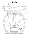
- FIG. 1 shows a food processor 1 according to the invention with a vessel 3 inserted therein and arranged on the vessel 3 cooking attachment 2.
- the food processor 1 is here for example designed as an electric motor driven agitator, which has a vessel 3 associated agitator, a vessel heater and similar facilities.
- the agitator, the heater and the like are controlled by means of a touch display or switches.
- the cooking attachment 2 has a bottom 4 with one or more bottom openings 5, through which steam emerging from the vessel 3 can enter into the cooking attachment in order to cook preparation goods contained in the cooking attachment 2. Likewise, condensate formed in the cooking attachment 2 can flow through the bottom openings 5 into the vessel in order to be available there for a renewed steam cycle.
- the cooking products 7 contained in the cooking attachment 2 can be, for example, vegetables, fish or the like.
- the cooking attachment 2 is advantageously closed by means of a lid 12, so that preferably a large part of the steam generated in the vessel 3 remains in the cooking attachment 2 and is not removed to the surroundings of the food processor 1.
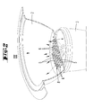
- FIG. 2 shows a vertical section through a arranged on a vessel 3 cooking attachment 2 according to a first embodiment.
- the bottom 4 of the cooking attachment 2 has a plurality of bottom openings 5, which are separated by a plurality of spacers 6.
- the bottom openings 5 and the spacers 6 are arranged in rows, wherein flow channels 8 for steam flows and condensate flows remain between successive spacers 6.
- the arrangement of the spacers 6 and the arrangement of the bottom openings 5 are superimposed so that a bottom opening 5 each in the circumferential direction is surrounded by a plurality of spacers 6, and conversely that a spacer 6 is surrounded by a plurality of bottom openings 5.
- bottom openings 5 or spacers 6 arranged in a central region of the structure.
- the arranged in an edge region bottom openings 5 and spacers 6 are correspondingly surrounded only over a certain peripheral portion of spacers 6 and bottom openings 5.
- the spacers 6 are formed as ribs, which are arranged parallel to adjacent ribs. Between the ribs are bottom openings 5, which are arranged in the region of the flow channels 8.
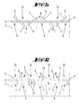
- FIG. 3 shows an enlarged plan view of a portion of the bottom 4 according to FIG. 2 ,
- the regular structure can be seen, which has a plurality of bottom openings 5 and a plurality of spacers 6.
- the bottom openings 5 are arranged in a plurality of mutually parallel rows.
- the spacers 6 are aligned in rows arranged parallel to one another, with a row of bottom openings 5 each alternating with a row of spacers 6.
- a spacer 6 is regularly surrounded by six bottom openings 5.
- Each bottom opening 5, on the other hand is surrounded either by two bottom openings 5 and two spacers 6 or by four spacers 6 and four bottom openings 5, depending on their position within the structure.
- the assignment is made by the ratio between the number of bottom openings 5 and the number of spacers 6, which is approximately 2: 1 here.
- FIG. 4 shows a cross section through adjacently arranged rows of bottom openings 5 and spacers 6.
- the rows of bottom openings 5 simultaneously form flow channels 8 for the flow of steam and / or condensate.
- the invention functions such that the preparation goods 7 contained in the cooking attachment 2 are spaced from the bottom openings 5 by means of the spacers 6, so that the bottom openings 5 are not closed by the preparation goods 7.
- the flow channels 8 remain open between the bottom openings 5 and the preparation goods 7.
- the bottom openings 5 are at the same time steam openings 9 for the flow through the bottom opening 5 with steam and condensate openings 10 for the flow through the bottom openings 5 with condensate.
- the ascending from the vessel 3 of the food processor 1 steam can flow through the bottom openings 5 in the cooking attachment 2 and are distributed there within the flow channels 8 on the bottom 4 of the cooking attachment 2.
- the hot steam preferably flows to those locations within the cooking attachment 2, which have the lowest temperature.
- FIGS. 5 and 6 show different embodiments of advantageous embodiments of the bottom openings 5.
- the bottom openings 5 are designed so that there are separate steam openings 9 for the flow of steam and condensate openings 10 for the flow of condensate. This is achieved in that the bottom openings 5 are surrounded by collar elements 11 whose opening cross-section tapers either in the direction of the cooking attachment 2 or in the direction of the vessel 3.
- the second opening bottom 5 shown on the left is, for example, a condensate opening 10.
- This has a collar element 11 which tapers in a direction from the interior of the cooking attachment 2 to the vessel 3.
- the projecting from the bottom 4 collar elements 11 at the same time form spacers 6 for spacing a arranged in the cooking attachment 2 preparation material 7 from the bottom openings. 5
- a partial region of the collar element 11 of the condensate opening 10 also forms a partial region of a collar element 11 of an adjacent (in the figure to the left) steam opening 9.
- This steam opening 9 has an opening cross-section which extends in a direction from the vessel 3 into the interior of the cooking attachment 2 tapered, that is, the taper extends in the direction opposite to the taper of the condensate opening 10 direction.
- the collar elements 11 have a polygonal, for example square, cross-sectional shape in a plan view, so that a partial region of a collar element 11 of a first bottom opening 5 can be formed by a partial region of a collar element 11 of an adjacent bottom opening 5.
- a collar element 11 completely surrounds a bottom opening 5 in the circumferential direction.
- the collar member 11 may be formed of spaced apart individual sections, so that further flow channels 8 remain on the bottom 4 of the cooking attachment 2.
- the collar elements 11 may be substantially perpendicular to the bottom 4 of the cooking attachment 2.
- the collar element 11 can be tapered stepwise, so that, for example, the side facing the vessel 3 provides a larger opening cross-section than the side facing the interior of the cooking attachment 2.
- steam openings 9 and condensate openings 10 can again be formed next to one another, the taper running in opposite directions.
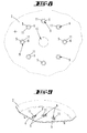
- FIG. 7 shows a third embodiment of the invention, according to which the bottom 4 of the cooking attachment 2 is inclined in the direction of the vessel 3 of the food processor 1.
- the lowest part of the inclined bottom 4 is located centrally in the middle of the bottom 4, so that in the cooking attachment 2 collected condensate can flow along the entire circumference of the bottom opening 5 to the bottom opening 5.
- the bottom 4 also has a plurality of bottom openings 5, which are formed as a steam opening 9.
- the vapor openings 9 are located with respect to the lowermost portion of the inclined bottom at a portion arranged above it, so that the condensate flows past the vapor openings 9 on its way in the direction of the condensate opening 10.
- the steam openings 9 have collar elements 11, which on the one hand serve as spacers 6 for the preparation items 7 arranged in the cooking attachment 2, and on the other hand for the protection of the vapor openings 9 against a flow through the condensate. In this way, the flows of steam and condensate, which regularly take place in opposite directions, are optimally separated from each other.
- FIG. 8 shows a plan view of a portion of the bottom 4 according to FIG. 7 , It can be seen that the condensate opening 10 in the circumferential direction of several, namely eight, steam openings 9 is surrounded. Each vapor opening 9 in this case has a collar element 11 which completely surrounds the bottom opening 5 in the circumferential direction.
- FIG. 9 shows an embodiment in which the vapor openings 9 are surrounded only in a certain peripheral portion of collar members 11.
- These collar elements 11 are advantageously located on that side of the bottom opening 5, which is first passed by a condensate flowing down the inclined bottom 4.
- the peripheral portion of the bottom opening 5, which is not protected by a collar element 11, is regularly not overflowed by condensate, since it lies deeper than the bottom opening 5.
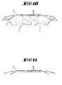
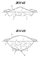
- FIGS. 10 to 13 show inventive embodiments of a lid 12 of the cooking attachment 2, with the aid of the adhesion of condensate on the inner side of the lid 12 can be prevented.
- the FIGS. 10 and 11 show, for example, structures which are called peaks ( FIG. 10 ) or as ribs ( FIG. 11 ) are configured. These structures provide an increased surface area for condensing vapor on the lid 12.
- the FIGS. 12 and 13 show an inclined formation of the lid 12, so that formed on the inner side of the lid 12 condensate flows in the direction of the cooking attachment 2 due to gravity.
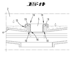
- FIG. 14 shows a fourth embodiment of the invention, in which a capillary 14 is formed on the cooking attachment 2.
- the capillary 14 is formed between a collar opening 11 delimiting a vapor opening 9 and a delimiting element 19 extending in a U-shaped manner over the collar element 11.
- the limiting element 19 is formed substantially annular and folded in the radial direction of the ring U-shaped.
- the capillary 14 advantageously has a diameter of a few ⁇ m in the radial direction of the bottom opening 5.
- the capillary 14 can be separated by walls (not shown) into individual partial capillaries.
- the capillary 14 has a first end region 15, which projects into the condensate collected on the bottom 4 of the cooking attachment 2.
- a second end region 16 of the capillary 14 is guided through the bottom opening 5 to the outside in the direction of the vessel 3. As soon as the condensate on the bottom 4 of the cooking attachment 2 comes into contact with the first end region 15, this can ascend into the capillary 14 due to the capillary effect and be conveyed in the direction of the vessel 3.
- FIGS. 15 and 16 show embodiments of a arranged on the inside of a cooking attachment 2 structure 18.
- the structure 8 according to FIG. 15 consists of mutually parallel ribs, which assign radially substantially to a bottom opening 5.
- the condensate formed in the cooking attachment 2 can between inflow adjacent ribs on the bottom opening 5.
- FIG. 16 In contrast, an embodiment is shown in which both the inside of the cooking attachment 2 and the inside of the lid 12 have different lengths of hairs.
- This structure 18 favors a solution of the condensate from the inner wall of the cooking attachment 2 or the lid 12, so that the condensate can be passed into the vessel 3 very quickly, where it is finally reheated and evaporated, to the preparation goods 7 in a new To heat cycle.
- FIG. 17 Finally shows a fifth embodiment of the invention, in which 12 vibration actuators 17 are arranged both on the cooking attachment 2 and on the lid.
- the vibration actuators 17 are here, for example, piezo-shakers, which are acted upon by means of a controller 13 so that they perform forced oscillations, which in turn are transmitted to the walls of the cooking attachment 2 and der Deckels 12. Due to the vibrations of the cooking attachment 2 or the cover 12, condensate adhering to the wall is released, so that it can quickly be returned to the vessel of the food processor 1 and is again available for heating the preparation goods 7.
Landscapes
- Engineering & Computer Science (AREA)
- Food Science & Technology (AREA)
- Cookers (AREA)
Priority Applications (9)
| Application Number | Priority Date | Filing Date | Title |
|---|---|---|---|
| EP17172483.4A EP3245918B1 (fr) | 2014-10-28 | 2015-10-12 | Accessoire de cuisson pour un récipient pouvant être chauffé d'un robot ménager |
| PL17170775T PL3241467T3 (pl) | 2014-10-28 | 2015-10-12 | Wkład do gotowania na parze do podgrzewanego naczynia urządzenia kuchennego |
| EP17172746.4A EP3245919B1 (fr) | 2014-10-28 | 2015-10-12 | Accessoire de cuisson pour un récipient pouvant être chauffé d'un robot ménager |
| PL17172751T PL3245920T3 (pl) | 2014-10-28 | 2015-10-12 | Wkład do gotowania na parze do podgrzewanego naczynia urządzenia kuchennego |
| PL15189261T PL3023040T3 (pl) | 2014-10-28 | 2015-10-12 | Robot kuchenny z ogrzewaną misą i umieszczoną na misie nasadką do gotowania |
| PL17172483T PL3245918T3 (pl) | 2014-10-28 | 2015-10-12 | Wkład do gotowania na parze do podgrzewanego naczynia urządzenia kuchennego |
| PL17172746T PL3245919T3 (pl) | 2014-10-28 | 2015-10-12 | Wkład do gotowania na parze podgrzewanego naczynia urządzenia kuchennego |
| EP17172751.4A EP3245920B1 (fr) | 2014-10-28 | 2015-10-12 | Accessoire de cuisson pour un récipient pouvant être chauffé d'un robot ménager |
| EP17170775.5A EP3241467B9 (fr) | 2014-10-28 | 2015-10-12 | Accessoire de cuisson pour un récipient pouvant être chauffé d'un robot ménager |
Applications Claiming Priority (1)
| Application Number | Priority Date | Filing Date | Title |
|---|---|---|---|
| DE102014115649.8A DE102014115649A1 (de) | 2014-10-28 | 2014-10-28 | Garaufsatz für ein aufheizbares Gefäß einer Küchenmaschine |
Related Child Applications (8)
| Application Number | Title | Priority Date | Filing Date |
|---|---|---|---|
| EP17172751.4A Division-Into EP3245920B1 (fr) | 2014-10-28 | 2015-10-12 | Accessoire de cuisson pour un récipient pouvant être chauffé d'un robot ménager |
| EP17172751.4A Division EP3245920B1 (fr) | 2014-10-28 | 2015-10-12 | Accessoire de cuisson pour un récipient pouvant être chauffé d'un robot ménager |
| EP17172746.4A Division-Into EP3245919B1 (fr) | 2014-10-28 | 2015-10-12 | Accessoire de cuisson pour un récipient pouvant être chauffé d'un robot ménager |
| EP17172746.4A Division EP3245919B1 (fr) | 2014-10-28 | 2015-10-12 | Accessoire de cuisson pour un récipient pouvant être chauffé d'un robot ménager |
| EP17172483.4A Division-Into EP3245918B1 (fr) | 2014-10-28 | 2015-10-12 | Accessoire de cuisson pour un récipient pouvant être chauffé d'un robot ménager |
| EP17172483.4A Division EP3245918B1 (fr) | 2014-10-28 | 2015-10-12 | Accessoire de cuisson pour un récipient pouvant être chauffé d'un robot ménager |
| EP17170775.5A Division-Into EP3241467B9 (fr) | 2014-10-28 | 2015-10-12 | Accessoire de cuisson pour un récipient pouvant être chauffé d'un robot ménager |
| EP17170775.5A Division EP3241467B9 (fr) | 2014-10-28 | 2015-10-12 | Accessoire de cuisson pour un récipient pouvant être chauffé d'un robot ménager |
Publications (3)
| Publication Number | Publication Date |
|---|---|
| EP3023040A2 true EP3023040A2 (fr) | 2016-05-25 |
| EP3023040A3 EP3023040A3 (fr) | 2016-08-17 |
| EP3023040B1 EP3023040B1 (fr) | 2018-04-04 |
Family
ID=54330605
Family Applications (5)
| Application Number | Title | Priority Date | Filing Date |
|---|---|---|---|
| EP15189261.9A Not-in-force EP3023040B1 (fr) | 2014-10-28 | 2015-10-12 | Accessoire de cuisson pour un recipient pouvant etre chauffe d'un robot menager |
| EP17172751.4A Active EP3245920B1 (fr) | 2014-10-28 | 2015-10-12 | Accessoire de cuisson pour un récipient pouvant être chauffé d'un robot ménager |
| EP17172483.4A Active EP3245918B1 (fr) | 2014-10-28 | 2015-10-12 | Accessoire de cuisson pour un récipient pouvant être chauffé d'un robot ménager |
| EP17172746.4A Active EP3245919B1 (fr) | 2014-10-28 | 2015-10-12 | Accessoire de cuisson pour un récipient pouvant être chauffé d'un robot ménager |
| EP17170775.5A Active EP3241467B9 (fr) | 2014-10-28 | 2015-10-12 | Accessoire de cuisson pour un récipient pouvant être chauffé d'un robot ménager |
Family Applications After (4)
| Application Number | Title | Priority Date | Filing Date |
|---|---|---|---|
| EP17172751.4A Active EP3245920B1 (fr) | 2014-10-28 | 2015-10-12 | Accessoire de cuisson pour un récipient pouvant être chauffé d'un robot ménager |
| EP17172483.4A Active EP3245918B1 (fr) | 2014-10-28 | 2015-10-12 | Accessoire de cuisson pour un récipient pouvant être chauffé d'un robot ménager |
| EP17172746.4A Active EP3245919B1 (fr) | 2014-10-28 | 2015-10-12 | Accessoire de cuisson pour un récipient pouvant être chauffé d'un robot ménager |
| EP17170775.5A Active EP3241467B9 (fr) | 2014-10-28 | 2015-10-12 | Accessoire de cuisson pour un récipient pouvant être chauffé d'un robot ménager |
Country Status (7)
| Country | Link |
|---|---|
| US (1) | US10285530B2 (fr) |
| EP (5) | EP3023040B1 (fr) |
| CN (1) | CN105534323B (fr) |
| DE (1) | DE102014115649A1 (fr) |
| ES (5) | ES2666825T3 (fr) |
| PL (5) | PL3245919T3 (fr) |
| PT (5) | PT3245919T (fr) |
Cited By (1)
| Publication number | Priority date | Publication date | Assignee | Title |
|---|---|---|---|---|
| WO2019077309A1 (fr) * | 2017-10-16 | 2019-04-25 | Wilkinson China Limited | Support résistant à la chaleur pour la préparation d'aliments et procédé |
Families Citing this family (7)
| Publication number | Priority date | Publication date | Assignee | Title |
|---|---|---|---|---|
| CN107232996A (zh) * | 2017-08-07 | 2017-10-10 | 杨玄星 | 快熟蒸菜盘 |
| DE202018006410U1 (de) | 2017-08-09 | 2020-04-23 | Sharkninja Operating Llc | Kochgerät und Komponenten davon |
| CN109349920B (zh) * | 2018-11-08 | 2024-04-30 | 珠海格力电器股份有限公司 | 一种烹饪设备 |
| WO2020176477A1 (fr) | 2019-02-25 | 2020-09-03 | Sharkninja Operating Llc | Système de cuisson avec protection |
| US20190254476A1 (en) | 2019-02-25 | 2019-08-22 | Sharkninja Operating Llc | Cooking device and components thereof |
| US11647861B2 (en) | 2020-03-30 | 2023-05-16 | Sharkninja Operating Llc | Cooking device and components thereof |
| CN112137398B (zh) * | 2020-10-26 | 2024-09-06 | 天津宝轩号餐饮有限公司 | 一种食材加热锅具 |
Citations (1)
| Publication number | Priority date | Publication date | Assignee | Title |
|---|---|---|---|---|
| WO1995029615A1 (fr) | 1994-04-28 | 1995-11-09 | Vorwerk & Co. Interholding Gmbh | Robot menager comportant un bac a agitation et un mecanisme d'entrainement de l'agitateur du bac |
Family Cites Families (17)
| Publication number | Priority date | Publication date | Assignee | Title |
|---|---|---|---|---|
| US1922419A (en) | 1932-02-17 | 1933-08-15 | Earl V Coulston | Accessory for cooking vessels |
| US4650968A (en) * | 1984-10-03 | 1987-03-17 | Williams James T | Steamer cooking device |
| EP0326105A1 (fr) | 1988-01-25 | 1989-08-02 | Henning Morgan Henderson | Appareil de cuisson à vapeur |
| US4920251A (en) * | 1989-02-28 | 1990-04-24 | Acry Industries, Incorporated | Compact, efficient, easy-to-clean food steamer for home use, with safety features and versatile modular food compartment |
| US5391262A (en) * | 1990-04-23 | 1995-02-21 | Wilkerson, Jr.; William | Solar still vibrator |
| US5097753B1 (en) * | 1991-06-10 | 1997-03-18 | Black & Decker Inc | Steam cooking utensil |
| NZ247900A (en) | 1992-11-04 | 1995-04-27 | Takahashi Kazuo | Reduced pressure fryer machine - food container has perforated bottom wall |
| US5275094A (en) * | 1993-05-17 | 1994-01-04 | Black & Decker Inc. | Divider basket for steam cooking utensil |
| CN2246475Y (zh) * | 1995-01-24 | 1997-02-05 | 杜春涯 | 防泡箅子 |
| JP2847484B2 (ja) | 1995-10-31 | 1999-01-20 | 健司 佐久間 | フライ食品の製造装置 |
| AT409582B (de) * | 2000-08-09 | 2002-09-25 | Holl Josef | Heissluftdeckel |
| JP3958601B2 (ja) * | 2001-03-13 | 2007-08-15 | 三星電子株式会社 | 調理容器 |
| EP2042060A1 (fr) * | 2007-09-25 | 2009-04-01 | Proprieta' Industriali S.r.l. | Appareil électroménager de préparation culinaire, avec un groupe de cuisson à vapeur |
| KR101255960B1 (ko) * | 2011-11-29 | 2013-04-23 | 삼성전기주식회사 | 스위치드 릴럭턴스 모터 |
| RU2624353C2 (ru) * | 2012-07-19 | 2017-07-03 | Конинклейке Филипс Н.В. | Устройство для варки пищевого продукта на пару |
| CN202775923U (zh) * | 2012-08-30 | 2013-03-13 | 韩景敏 | 导水式箅子及导水式笼屉 |
| EP2832273A1 (fr) | 2013-08-02 | 2015-02-04 | Compania Espanola de Electromenaje, SA | Dispositif de préparation d'aliments à la vapeur et récipient à vapeur |
-
2014
- 2014-10-28 DE DE102014115649.8A patent/DE102014115649A1/de not_active Withdrawn
-
2015
- 2015-10-12 PT PT171727464T patent/PT3245919T/pt unknown
- 2015-10-12 PT PT171724834T patent/PT3245918T/pt unknown
- 2015-10-12 ES ES15189261.9T patent/ES2666825T3/es active Active
- 2015-10-12 EP EP15189261.9A patent/EP3023040B1/fr not_active Not-in-force
- 2015-10-12 PL PL17172746T patent/PL3245919T3/pl unknown
- 2015-10-12 PL PL17172751T patent/PL3245920T3/pl unknown
- 2015-10-12 PL PL17170775T patent/PL3241467T3/pl unknown
- 2015-10-12 EP EP17172751.4A patent/EP3245920B1/fr active Active
- 2015-10-12 EP EP17172483.4A patent/EP3245918B1/fr active Active
- 2015-10-12 PT PT151892619T patent/PT3023040T/pt unknown
- 2015-10-12 PT PT171707755T patent/PT3241467T/pt unknown
- 2015-10-12 EP EP17172746.4A patent/EP3245919B1/fr active Active
- 2015-10-12 PL PL15189261T patent/PL3023040T3/pl unknown
- 2015-10-12 ES ES17172483T patent/ES2767360T3/es active Active
- 2015-10-12 ES ES17170775T patent/ES2791067T3/es active Active
- 2015-10-12 PL PL17172483T patent/PL3245918T3/pl unknown
- 2015-10-12 ES ES17172746T patent/ES2762112T3/es active Active
- 2015-10-12 ES ES17172751T patent/ES2773986T3/es active Active
- 2015-10-12 EP EP17170775.5A patent/EP3241467B9/fr active Active
- 2015-10-12 PT PT171727514T patent/PT3245920T/pt unknown
- 2015-10-27 US US14/923,601 patent/US10285530B2/en active Active
- 2015-10-28 CN CN201511022637.1A patent/CN105534323B/zh not_active Expired - Fee Related
Patent Citations (1)
| Publication number | Priority date | Publication date | Assignee | Title |
|---|---|---|---|---|
| WO1995029615A1 (fr) | 1994-04-28 | 1995-11-09 | Vorwerk & Co. Interholding Gmbh | Robot menager comportant un bac a agitation et un mecanisme d'entrainement de l'agitateur du bac |
Cited By (1)
| Publication number | Priority date | Publication date | Assignee | Title |
|---|---|---|---|---|
| WO2019077309A1 (fr) * | 2017-10-16 | 2019-04-25 | Wilkinson China Limited | Support résistant à la chaleur pour la préparation d'aliments et procédé |
Also Published As
| Publication number | Publication date |
|---|---|
| PL3245920T3 (pl) | 2020-06-01 |
| EP3023040A3 (fr) | 2016-08-17 |
| EP3023040B1 (fr) | 2018-04-04 |
| CN105534323A (zh) | 2016-05-04 |
| EP3245918B1 (fr) | 2019-12-11 |
| CN105534323B (zh) | 2020-08-18 |
| PL3245919T3 (pl) | 2020-05-18 |
| PL3023040T3 (pl) | 2019-01-31 |
| EP3245919A1 (fr) | 2017-11-22 |
| EP3245920A1 (fr) | 2017-11-22 |
| ES2773986T3 (es) | 2020-07-16 |
| PL3241467T3 (pl) | 2020-06-29 |
| PT3245919T (pt) | 2019-12-11 |
| ES2666825T3 (es) | 2018-05-08 |
| EP3241467B9 (fr) | 2020-06-10 |
| EP3245919B1 (fr) | 2019-11-27 |
| ES2791067T3 (es) | 2020-10-30 |
| EP3241467A1 (fr) | 2017-11-08 |
| ES2767360T3 (es) | 2020-06-17 |
| EP3241467B1 (fr) | 2020-02-12 |
| PT3245918T (pt) | 2020-01-29 |
| EP3245920B1 (fr) | 2019-12-11 |
| ES2762112T3 (es) | 2020-05-22 |
| US10285530B2 (en) | 2019-05-14 |
| US20160113432A1 (en) | 2016-04-28 |
| PL3245918T3 (pl) | 2020-06-01 |
| PT3023040T (pt) | 2018-05-02 |
| PT3245920T (pt) | 2020-01-21 |
| EP3245918A1 (fr) | 2017-11-22 |
| PT3241467T (pt) | 2020-03-04 |
| DE102014115649A1 (de) | 2016-04-28 |
Similar Documents
| Publication | Publication Date | Title |
|---|---|---|
| EP3245920B1 (fr) | Accessoire de cuisson pour un récipient pouvant être chauffé d'un robot ménager | |
| DE60317166T2 (de) | Vorrichtung und verfahren zur behandlung von flüssigkeiten | |
| EP3265195A1 (fr) | Collecteur de support pour colonne à garnissage | |
| EP2941309B1 (fr) | Plateau d'échange de matière | |
| DE2950194A1 (de) | Verfahren und vorrichtung zum sammeln einer fluessigkeit an einem ort und zum foerdern der fluessigkeit zur verwendung an einem zweiten ort | |
| EP2468376A1 (fr) | Distributeur de liquide pour colonne avec garnissage | |
| WO2017157535A1 (fr) | Dispositif de séparation pour échangeurs de chaleur enroulés permettant de séparer une phase gazeuse d'une phase liquide d'un milieu biphasique guidé côté enveloppe | |
| DE102017210276A1 (de) | Wärmetauscher, insbesondere Abgaswärmetauscher, für ein Kraftfahrzeug | |
| EP2927632A1 (fr) | Échangeur thermique | |
| DE1942433C3 (de) | Brennelement für Kernreaktoren | |
| EP2047020B1 (fr) | Dispositif pour la fabrication de non-tissés ajourés | |
| DE102017130546A1 (de) | Kühlkanal mit Damm und Trichter | |
| EP1876391A1 (fr) | Échangeur de chaleur et méthode pour sa fabrication | |
| EP3239641A1 (fr) | Tube plat pour un caloporteur | |
| EP2975350A1 (fr) | Échangeur thermique | |
| EP1486126B1 (fr) | Procédé et appareil pour un traitement thermique de masses de sucre | |
| DE102004012607A1 (de) | Vorrichtung und Verfahren zur thermischen Behandlung einer Süßwarenmasse | |
| DE102012222148A1 (de) | Gargutträger mit Löchern in einem Auflagebereich sowie Dampfgargerät mit einem derartigen Gargutsträger | |
| DD275619B5 (de) | Fluessigkeitsverteilereinrichtung mit dampfabfuehrungssektion fuer gegenstromfallfilterverdampfer | |
| EP3250860B1 (fr) | Chaudière de chauffage | |
| EP1834693A1 (fr) | Corps de remplissage en tissu | |
| DE102006026726A1 (de) | Stoffaustauschkolonne mit Kaminhalsglocken-Böden | |
| DE102014009332A1 (de) | Schleuderkorb | |
| DE2657486B2 (de) | Saunaofen | |
| DE102006036669A1 (de) | Heizkammer eines Kristallisationsverdampfers |
Legal Events
| Date | Code | Title | Description |
|---|---|---|---|
| AK | Designated contracting states |
Kind code of ref document: A2 Designated state(s): AL AT BE BG CH CY CZ DE DK EE ES FI FR GB GR HR HU IE IS IT LI LT LU LV MC MK MT NL NO PL PT RO RS SE SI SK SM TR |
|
| AX | Request for extension of the european patent |
Extension state: BA ME |
|
| PUAI | Public reference made under article 153(3) epc to a published international application that has entered the european phase |
Free format text: ORIGINAL CODE: 0009012 |
|
| PUAL | Search report despatched |
Free format text: ORIGINAL CODE: 0009013 |
|
| AK | Designated contracting states |
Kind code of ref document: A3 Designated state(s): AL AT BE BG CH CY CZ DE DK EE ES FI FR GB GR HR HU IE IS IT LI LT LU LV MC MK MT NL NO PL PT RO RS SE SI SK SM TR |
|
| AX | Request for extension of the european patent |
Extension state: BA ME |
|
| RIC1 | Information provided on ipc code assigned before grant |
Ipc: A47J 43/07 20060101ALN20160714BHEP Ipc: A47J 27/04 20060101ALI20160714BHEP Ipc: A47J 36/20 20060101AFI20160714BHEP |
|
| 17P | Request for examination filed |
Effective date: 20170214 |
|
| RBV | Designated contracting states (corrected) |
Designated state(s): AL AT BE BG CH CY CZ DE DK EE ES FI FR GB GR HR HU IE IS IT LI LT LU LV MC MK MT NL NO PL PT RO RS SE SI SK SM TR |
|
| GRAP | Despatch of communication of intention to grant a patent |
Free format text: ORIGINAL CODE: EPIDOSNIGR1 |
|
| RIC1 | Information provided on ipc code assigned before grant |
Ipc: A47J 36/20 20060101AFI20171005BHEP Ipc: A47J 43/07 20060101ALN20171005BHEP Ipc: A47J 27/04 20060101ALI20171005BHEP |
|
| INTG | Intention to grant announced |
Effective date: 20171103 |
|
| RIN1 | Information on inventor provided before grant (corrected) |
Inventor name: CORNELISSEN, MARKUS |
|
| GRAS | Grant fee paid |
Free format text: ORIGINAL CODE: EPIDOSNIGR3 |
|
| GRAA | (expected) grant |
Free format text: ORIGINAL CODE: 0009210 |
|
| AK | Designated contracting states |
Kind code of ref document: B1 Designated state(s): AL AT BE BG CH CY CZ DE DK EE ES FI FR GB GR HR HU IE IS IT LI LT LU LV MC MK MT NL NO PL PT RO RS SE SI SK SM TR |
|
| REG | Reference to a national code |
Ref country code: GB Ref legal event code: FG4D Free format text: NOT ENGLISH |
|
| REG | Reference to a national code |
Ref country code: CH Ref legal event code: EP |
|
| REG | Reference to a national code |
Ref country code: AT Ref legal event code: REF Ref document number: 984646 Country of ref document: AT Kind code of ref document: T Effective date: 20180415 |
|
| REG | Reference to a national code |
Ref country code: IE Ref legal event code: FG4D Free format text: LANGUAGE OF EP DOCUMENT: GERMAN Ref country code: PT Ref legal event code: SC4A Ref document number: 3023040 Country of ref document: PT Date of ref document: 20180502 Kind code of ref document: T Free format text: AVAILABILITY OF NATIONAL TRANSLATION Effective date: 20180423 |
|
| REG | Reference to a national code |
Ref country code: DE Ref legal event code: R096 Ref document number: 502015003710 Country of ref document: DE |
|
| REG | Reference to a national code |
Ref country code: ES Ref legal event code: FG2A Ref document number: 2666825 Country of ref document: ES Kind code of ref document: T3 Effective date: 20180508 |
|
| REG | Reference to a national code |
Ref country code: NL Ref legal event code: MP Effective date: 20180404 |
|
| REG | Reference to a national code |
Ref country code: LT Ref legal event code: MG4D |
|
| PG25 | Lapsed in a contracting state [announced via postgrant information from national office to epo] |
Ref country code: NL Free format text: LAPSE BECAUSE OF FAILURE TO SUBMIT A TRANSLATION OF THE DESCRIPTION OR TO PAY THE FEE WITHIN THE PRESCRIBED TIME-LIMIT Effective date: 20180404 |
|
| REG | Reference to a national code |
Ref country code: FR Ref legal event code: PLFP Year of fee payment: 4 |
|
| PG25 | Lapsed in a contracting state [announced via postgrant information from national office to epo] |
Ref country code: BG Free format text: LAPSE BECAUSE OF FAILURE TO SUBMIT A TRANSLATION OF THE DESCRIPTION OR TO PAY THE FEE WITHIN THE PRESCRIBED TIME-LIMIT Effective date: 20180704 Ref country code: FI Free format text: LAPSE BECAUSE OF FAILURE TO SUBMIT A TRANSLATION OF THE DESCRIPTION OR TO PAY THE FEE WITHIN THE PRESCRIBED TIME-LIMIT Effective date: 20180404 Ref country code: AL Free format text: LAPSE BECAUSE OF FAILURE TO SUBMIT A TRANSLATION OF THE DESCRIPTION OR TO PAY THE FEE WITHIN THE PRESCRIBED TIME-LIMIT Effective date: 20180404 Ref country code: SE Free format text: LAPSE BECAUSE OF FAILURE TO SUBMIT A TRANSLATION OF THE DESCRIPTION OR TO PAY THE FEE WITHIN THE PRESCRIBED TIME-LIMIT Effective date: 20180404 Ref country code: NO Free format text: LAPSE BECAUSE OF FAILURE TO SUBMIT A TRANSLATION OF THE DESCRIPTION OR TO PAY THE FEE WITHIN THE PRESCRIBED TIME-LIMIT Effective date: 20180704 Ref country code: LT Free format text: LAPSE BECAUSE OF FAILURE TO SUBMIT A TRANSLATION OF THE DESCRIPTION OR TO PAY THE FEE WITHIN THE PRESCRIBED TIME-LIMIT Effective date: 20180404 |
|
| PG25 | Lapsed in a contracting state [announced via postgrant information from national office to epo] |
Ref country code: HR Free format text: LAPSE BECAUSE OF FAILURE TO SUBMIT A TRANSLATION OF THE DESCRIPTION OR TO PAY THE FEE WITHIN THE PRESCRIBED TIME-LIMIT Effective date: 20180404 Ref country code: RS Free format text: LAPSE BECAUSE OF FAILURE TO SUBMIT A TRANSLATION OF THE DESCRIPTION OR TO PAY THE FEE WITHIN THE PRESCRIBED TIME-LIMIT Effective date: 20180404 Ref country code: GR Free format text: LAPSE BECAUSE OF FAILURE TO SUBMIT A TRANSLATION OF THE DESCRIPTION OR TO PAY THE FEE WITHIN THE PRESCRIBED TIME-LIMIT Effective date: 20180705 Ref country code: LV Free format text: LAPSE BECAUSE OF FAILURE TO SUBMIT A TRANSLATION OF THE DESCRIPTION OR TO PAY THE FEE WITHIN THE PRESCRIBED TIME-LIMIT Effective date: 20180404 |
|
| REG | Reference to a national code |
Ref country code: DE Ref legal event code: R097 Ref document number: 502015003710 Country of ref document: DE |
|
| PG25 | Lapsed in a contracting state [announced via postgrant information from national office to epo] |
Ref country code: CZ Free format text: LAPSE BECAUSE OF FAILURE TO SUBMIT A TRANSLATION OF THE DESCRIPTION OR TO PAY THE FEE WITHIN THE PRESCRIBED TIME-LIMIT Effective date: 20180404 Ref country code: SK Free format text: LAPSE BECAUSE OF FAILURE TO SUBMIT A TRANSLATION OF THE DESCRIPTION OR TO PAY THE FEE WITHIN THE PRESCRIBED TIME-LIMIT Effective date: 20180404 Ref country code: RO Free format text: LAPSE BECAUSE OF FAILURE TO SUBMIT A TRANSLATION OF THE DESCRIPTION OR TO PAY THE FEE WITHIN THE PRESCRIBED TIME-LIMIT Effective date: 20180404 Ref country code: EE Free format text: LAPSE BECAUSE OF FAILURE TO SUBMIT A TRANSLATION OF THE DESCRIPTION OR TO PAY THE FEE WITHIN THE PRESCRIBED TIME-LIMIT Effective date: 20180404 Ref country code: DK Free format text: LAPSE BECAUSE OF FAILURE TO SUBMIT A TRANSLATION OF THE DESCRIPTION OR TO PAY THE FEE WITHIN THE PRESCRIBED TIME-LIMIT Effective date: 20180404 |
|
| PLBE | No opposition filed within time limit |
Free format text: ORIGINAL CODE: 0009261 |
|
| STAA | Information on the status of an ep patent application or granted ep patent |
Free format text: STATUS: NO OPPOSITION FILED WITHIN TIME LIMIT |
|
| PG25 | Lapsed in a contracting state [announced via postgrant information from national office to epo] |
Ref country code: SM Free format text: LAPSE BECAUSE OF FAILURE TO SUBMIT A TRANSLATION OF THE DESCRIPTION OR TO PAY THE FEE WITHIN THE PRESCRIBED TIME-LIMIT Effective date: 20180404 |
|
| 26N | No opposition filed |
Effective date: 20190107 |
|
| PG25 | Lapsed in a contracting state [announced via postgrant information from national office to epo] |
Ref country code: SI Free format text: LAPSE BECAUSE OF FAILURE TO SUBMIT A TRANSLATION OF THE DESCRIPTION OR TO PAY THE FEE WITHIN THE PRESCRIBED TIME-LIMIT Effective date: 20180404 |
|
| REG | Reference to a national code |
Ref country code: CH Ref legal event code: PL |
|
| REG | Reference to a national code |
Ref country code: BE Ref legal event code: MM Effective date: 20181031 |
|
| PG25 | Lapsed in a contracting state [announced via postgrant information from national office to epo] |
Ref country code: MC Free format text: LAPSE BECAUSE OF FAILURE TO SUBMIT A TRANSLATION OF THE DESCRIPTION OR TO PAY THE FEE WITHIN THE PRESCRIBED TIME-LIMIT Effective date: 20180404 Ref country code: LU Free format text: LAPSE BECAUSE OF NON-PAYMENT OF DUE FEES Effective date: 20181012 |
|
| REG | Reference to a national code |
Ref country code: IE Ref legal event code: MM4A |
|
| PG25 | Lapsed in a contracting state [announced via postgrant information from national office to epo] |
Ref country code: CH Free format text: LAPSE BECAUSE OF NON-PAYMENT OF DUE FEES Effective date: 20181031 Ref country code: LI Free format text: LAPSE BECAUSE OF NON-PAYMENT OF DUE FEES Effective date: 20181031 Ref country code: BE Free format text: LAPSE BECAUSE OF NON-PAYMENT OF DUE FEES Effective date: 20181031 |
|
| PG25 | Lapsed in a contracting state [announced via postgrant information from national office to epo] |
Ref country code: IE Free format text: LAPSE BECAUSE OF NON-PAYMENT OF DUE FEES Effective date: 20181012 |
|
| PG25 | Lapsed in a contracting state [announced via postgrant information from national office to epo] |
Ref country code: MT Free format text: LAPSE BECAUSE OF FAILURE TO SUBMIT A TRANSLATION OF THE DESCRIPTION OR TO PAY THE FEE WITHIN THE PRESCRIBED TIME-LIMIT Effective date: 20180404 |
|
| PGFP | Annual fee paid to national office [announced via postgrant information from national office to epo] |
Ref country code: TR Payment date: 20191010 Year of fee payment: 5 |
|
| PG25 | Lapsed in a contracting state [announced via postgrant information from national office to epo] |
Ref country code: MK Free format text: LAPSE BECAUSE OF NON-PAYMENT OF DUE FEES Effective date: 20180404 Ref country code: CY Free format text: LAPSE BECAUSE OF FAILURE TO SUBMIT A TRANSLATION OF THE DESCRIPTION OR TO PAY THE FEE WITHIN THE PRESCRIBED TIME-LIMIT Effective date: 20180404 Ref country code: HU Free format text: LAPSE BECAUSE OF FAILURE TO SUBMIT A TRANSLATION OF THE DESCRIPTION OR TO PAY THE FEE WITHIN THE PRESCRIBED TIME-LIMIT; INVALID AB INITIO Effective date: 20151012 |
|
| PG25 | Lapsed in a contracting state [announced via postgrant information from national office to epo] |
Ref country code: IS Free format text: LAPSE BECAUSE OF FAILURE TO SUBMIT A TRANSLATION OF THE DESCRIPTION OR TO PAY THE FEE WITHIN THE PRESCRIBED TIME-LIMIT Effective date: 20180804 |
|
| REG | Reference to a national code |
Ref country code: AT Ref legal event code: MM01 Ref document number: 984646 Country of ref document: AT Kind code of ref document: T Effective date: 20201012 |
|
| PG25 | Lapsed in a contracting state [announced via postgrant information from national office to epo] |
Ref country code: AT Free format text: LAPSE BECAUSE OF NON-PAYMENT OF DUE FEES Effective date: 20201012 |
|
| PG25 | Lapsed in a contracting state [announced via postgrant information from national office to epo] |
Ref country code: TR Free format text: LAPSE BECAUSE OF NON-PAYMENT OF DUE FEES Effective date: 20201012 |
|
| PGFP | Annual fee paid to national office [announced via postgrant information from national office to epo] |
Ref country code: FR Payment date: 20221020 Year of fee payment: 8 |
|
| PGFP | Annual fee paid to national office [announced via postgrant information from national office to epo] |
Ref country code: PT Payment date: 20221011 Year of fee payment: 8 Ref country code: IT Payment date: 20221031 Year of fee payment: 8 Ref country code: GB Payment date: 20221024 Year of fee payment: 8 Ref country code: ES Payment date: 20221118 Year of fee payment: 8 Ref country code: DE Payment date: 20221020 Year of fee payment: 8 |
|
| PGFP | Annual fee paid to national office [announced via postgrant information from national office to epo] |
Ref country code: PL Payment date: 20220930 Year of fee payment: 8 |
|
| P01 | Opt-out of the competence of the unified patent court (upc) registered |
Effective date: 20230517 |
|
| REG | Reference to a national code |
Ref country code: DE Ref legal event code: R119 Ref document number: 502015003710 Country of ref document: DE |
|
| GBPC | Gb: european patent ceased through non-payment of renewal fee |
Effective date: 20231012 |
|
| PG25 | Lapsed in a contracting state [announced via postgrant information from national office to epo] |
Ref country code: GB Free format text: LAPSE BECAUSE OF NON-PAYMENT OF DUE FEES Effective date: 20231012 |
|
| PG25 | Lapsed in a contracting state [announced via postgrant information from national office to epo] |
Ref country code: GB Free format text: LAPSE BECAUSE OF NON-PAYMENT OF DUE FEES Effective date: 20231012 Ref country code: FR Free format text: LAPSE BECAUSE OF NON-PAYMENT OF DUE FEES Effective date: 20231031 Ref country code: DE Free format text: LAPSE BECAUSE OF NON-PAYMENT OF DUE FEES Effective date: 20240501 |
|
| PG25 | Lapsed in a contracting state [announced via postgrant information from national office to epo] |
Ref country code: PT Free format text: LAPSE BECAUSE OF NON-PAYMENT OF DUE FEES Effective date: 20240412 |
|
| PG25 | Lapsed in a contracting state [announced via postgrant information from national office to epo] |
Ref country code: PT Free format text: LAPSE BECAUSE OF NON-PAYMENT OF DUE FEES Effective date: 20240412 |
|
| REG | Reference to a national code |
Ref country code: ES Ref legal event code: FD2A Effective date: 20241202 |
|
| PG25 | Lapsed in a contracting state [announced via postgrant information from national office to epo] |
Ref country code: IT Free format text: LAPSE BECAUSE OF NON-PAYMENT OF DUE FEES Effective date: 20231012 |
|
| PG25 | Lapsed in a contracting state [announced via postgrant information from national office to epo] |
Ref country code: IT Free format text: LAPSE BECAUSE OF NON-PAYMENT OF DUE FEES Effective date: 20231012 |
|
| PG25 | Lapsed in a contracting state [announced via postgrant information from national office to epo] |
Ref country code: ES Free format text: LAPSE BECAUSE OF NON-PAYMENT OF DUE FEES Effective date: 20231013 |
|
| PG25 | Lapsed in a contracting state [announced via postgrant information from national office to epo] |
Ref country code: ES Free format text: LAPSE BECAUSE OF NON-PAYMENT OF DUE FEES Effective date: 20231013 |
|
| PG25 | Lapsed in a contracting state [announced via postgrant information from national office to epo] |
Ref country code: PL Free format text: LAPSE BECAUSE OF NON-PAYMENT OF DUE FEES Effective date: 20231012 |