EP3023325A1 - Composant de vélo comprenant une butée et butée - Google Patents
Composant de vélo comprenant une butée et butée Download PDFInfo
- Publication number
- EP3023325A1 EP3023325A1 EP15196001.0A EP15196001A EP3023325A1 EP 3023325 A1 EP3023325 A1 EP 3023325A1 EP 15196001 A EP15196001 A EP 15196001A EP 3023325 A1 EP3023325 A1 EP 3023325A1
- Authority
- EP
- European Patent Office
- Prior art keywords
- stop
- component
- bicycle
- flange
- ring
- Prior art date
- Legal status (The legal status is an assumption and is not a legal conclusion. Google has not performed a legal analysis and makes no representation as to the accuracy of the status listed.)
- Granted
Links
Images

Classifications
-
- B—PERFORMING OPERATIONS; TRANSPORTING
- B60—VEHICLES IN GENERAL
- B60B—VEHICLE WHEELS; CASTORS; AXLES FOR WHEELS OR CASTORS; INCREASING WHEEL ADHESION
- B60B27/00—Hubs
- B60B27/02—Hubs adapted to be rotatably arranged on axle
- B60B27/023—Hubs adapted to be rotatably arranged on axle specially adapted for bicycles
- B60B27/026—Hubs adapted to be rotatably arranged on axle specially adapted for bicycles comprising quick release devices
-
- B—PERFORMING OPERATIONS; TRANSPORTING
- B60—VEHICLES IN GENERAL
- B60B—VEHICLE WHEELS; CASTORS; AXLES FOR WHEELS OR CASTORS; INCREASING WHEEL ADHESION
- B60B27/00—Hubs
- B60B27/0047—Hubs characterised by functional integration of other elements
- B60B27/0052—Hubs characterised by functional integration of other elements the element being a brake disc
-
- B—PERFORMING OPERATIONS; TRANSPORTING
- B60—VEHICLES IN GENERAL
- B60B—VEHICLE WHEELS; CASTORS; AXLES FOR WHEELS OR CASTORS; INCREASING WHEEL ADHESION
- B60B27/00—Hubs
- B60B27/0073—Hubs characterised by sealing means
-
- B—PERFORMING OPERATIONS; TRANSPORTING
- B60—VEHICLES IN GENERAL
- B60B—VEHICLE WHEELS; CASTORS; AXLES FOR WHEELS OR CASTORS; INCREASING WHEEL ADHESION
- B60B27/00—Hubs
- B60B27/02—Hubs adapted to be rotatably arranged on axle
- B60B27/023—Hubs adapted to be rotatably arranged on axle specially adapted for bicycles
-
- B—PERFORMING OPERATIONS; TRANSPORTING
- B62—LAND VEHICLES FOR TRAVELLING OTHERWISE THAN ON RAILS
- B62K—CYCLES; CYCLE FRAMES; CYCLE STEERING DEVICES; RIDER-OPERATED TERMINAL CONTROLS SPECIALLY ADAPTED FOR CYCLES; CYCLE AXLE SUSPENSIONS; CYCLE SIDECARS, FORECARS, OR THE LIKE
- B62K19/00—Cycle frames
- B62K19/30—Frame parts shaped to receive other cycle parts or accessories
- B62K19/38—Frame parts shaped to receive other cycle parts or accessories for attaching brake members
-
- B—PERFORMING OPERATIONS; TRANSPORTING
- B62—LAND VEHICLES FOR TRAVELLING OTHERWISE THAN ON RAILS
- B62K—CYCLES; CYCLE FRAMES; CYCLE STEERING DEVICES; RIDER-OPERATED TERMINAL CONTROLS SPECIALLY ADAPTED FOR CYCLES; CYCLE AXLE SUSPENSIONS; CYCLE SIDECARS, FORECARS, OR THE LIKE
- B62K25/00—Axle suspensions
- B62K25/02—Axle suspensions for mounting axles rigidly on cycle frame or fork, e.g. adjustably
-
- B—PERFORMING OPERATIONS; TRANSPORTING
- B60—VEHICLES IN GENERAL
- B60B—VEHICLE WHEELS; CASTORS; AXLES FOR WHEELS OR CASTORS; INCREASING WHEEL ADHESION
- B60B27/00—Hubs
- B60B27/0005—Hubs with ball bearings
-
- B—PERFORMING OPERATIONS; TRANSPORTING
- B60—VEHICLES IN GENERAL
- B60B—VEHICLE WHEELS; CASTORS; AXLES FOR WHEELS OR CASTORS; INCREASING WHEEL ADHESION
- B60B27/00—Hubs
- B60B27/0015—Hubs for driven wheels
-
- B—PERFORMING OPERATIONS; TRANSPORTING
- B60—VEHICLES IN GENERAL
- B60B—VEHICLE WHEELS; CASTORS; AXLES FOR WHEELS OR CASTORS; INCREASING WHEEL ADHESION
- B60B27/00—Hubs
- B60B27/0078—Hubs characterised by the fixation of bearings
-
- B—PERFORMING OPERATIONS; TRANSPORTING
- B60—VEHICLES IN GENERAL
- B60Y—INDEXING SCHEME RELATING TO ASPECTS CROSS-CUTTING VEHICLE TECHNOLOGY
- B60Y2200/00—Type of vehicle
- B60Y2200/10—Road Vehicles
- B60Y2200/13—Bicycles; Tricycles
-
- B—PERFORMING OPERATIONS; TRANSPORTING
- B62—LAND VEHICLES FOR TRAVELLING OTHERWISE THAN ON RAILS
- B62K—CYCLES; CYCLE FRAMES; CYCLE STEERING DEVICES; RIDER-OPERATED TERMINAL CONTROLS SPECIALLY ADAPTED FOR CYCLES; CYCLE AXLE SUSPENSIONS; CYCLE SIDECARS, FORECARS, OR THE LIKE
- B62K19/00—Cycle frames
- B62K19/30—Frame parts shaped to receive other cycle parts or accessories
- B62K19/34—Bottom brackets
Definitions
- the present invention relates to a bicycle component comprising a hub shell for an impeller of an at least partially muscle-powered bicycle and an end stop for a hub of an at least partially muscle-powered bicycle and a bicycle with a frame, a fork and an at least partially human-powered drive.
- the bicycle component and the bicycle at least one end stop to fix the wheel of a two-wheeler to the dropouts.
- Hubs for thru-axle systems have been increasingly used for some years, with the thru-axle having a thread at one end, with which it is threaded into an internal thread on the dropout the fork or the frame is screwed.
- Such thru axles allow a higher rigidity of the system.
- the abutment surface of the axle or end stop has been increased at the dropout of a frame.
- the maximum diameter of the end stop must be smaller than the free inner diameter of such a fixing ring.
- a bicycle component according to the invention has a hub shell for an impeller of an at least partially muscle-operated bicycle.
- the hub shell is rotatably supported via at least one bearing device.
- At least one end of the hub shell an end stop is arranged.
- the end stop has an inner stop with an inner stop surface for transferring a clamping force to the bearing device and an outer at least a part of the clamping force transmitted stop with an outer stop surface.
- the end stop comprises a first and at least one second stop component transmitting the clamping force.
- the end stop consists of a first and at least one second stop component transmitting the clamping force.
- the outer stop has a larger stop surface and / or a larger outer diameter than the inner stop.
- the bicycle component according to the invention has many advantages.
- a significant advantage of the bicycle component according to the invention is that the stop consists of two at least a part of the clamping force transmitted stop components. This allows the end stop to be divided into two separate parts, each transmitting power and, for example, have different outer dimensions. This makes it possible to pre-assemble the bicycle component - in particular a hub - in the factory of the hub manufacturer.
- the bicycle manufacturer in turn can z. B. remove only the outer stop component of the end stop to mount a brake disc or the like. Or the bicycle manufacturer assembles the outer stop component only after mounting the brake disc. As a result, in both cases, the interior of the hub remains unaffected by the mounting of such a disc brake. Assembly is faster and fewer errors can occur.
- the end stop can be made more flexible in its outer dimensions than it was in the prior art.
- the inner stop here is the axially inner stop and the outer stop is understood to be the axially outer stop.
- the outer stop is designed to receive at least part of the clamping force of a dropout or a frame component.
- the bicycle component can be designed for receiving a thru axle or for fastening by means of a quick release.
- it is preferred that the inner axial end or the inner stop is immersed in a first end of the hub shell.
- the outer stop at the outer axial end preferably projects outwardly from the hub shell.
- the end stop according to the invention has the inner stop with the inner stop surface.
- the inner stop surface is suitable for transferring the clamping force to the bearing device. This means that the inner stop transmits the clamping force completely or partially indirectly and / or completely or partially directly to the bearing device.
- a force-transmitting component between the bearing device and the inner stop.
- Such a force-transmitting component can be designed to transmit the clamping force completely or partially to the bearing device.
- the inner stop abuts directly against the bearing device.
- the end stop can also be referred to as an adapter unit.
- the abutment surfaces of the outer stop and the inner stop can be decoupled from each other. As a result, greater design freedom is available, allowing a stiffer connection of the bicycle component with the frame or the fork of the bicycle.
- the outer stop has a larger outer diameter than a maximum outer diameter of the bearing device.
- the outer stop has a larger outer diameter than a maximum inner diameter of the hub shell.
- the inner stop is formed on the first stop component with the inner stop surface and / or it is formed on the second stop component of the outer stop with the outer stop surface. It is possible that at least one stop surface, namely the inner stop surface and / or the outer stop surface, are partially provided by the first stop component and partially by the second stop component. This is for example possible if one of the two stop components radially surrounds the other stop component, so that at one or both ends of the stop the inner or outer stop are respectively formed by surfaces of the first and / or second stop component.
- At least one stop is at least one stop (inner and / or outer stop) by only one of each Stop components formed.
- the axially inner stop is formed only and / or completely by the first stop component.
- the axially outer stop is formed only and / or completely by the second stop component.
- a brake disc receptacle and in particular a standard brake disc receptacle is formed with a particular non-round outer contour.
- a fixing receptacle with an internal thread is formed on the hub shell in an axial region of the brake disc receptacle.
- a fixing ring for fixing a brake disc can be attached to the fixing receptacle. In simple cases, this is done by providing an external thread on the fixing ring, which is screwed into an internal thread on the fixing receptacle. But it is also possible that the fixing ring is mounted laterally on the hub shell via one or more separate screws or the like.
- a recorded on the brake disc holder brake disc is fixed in the axial direction by the fixing ring, while a rotationally fixed recording is ensured by the non-circular outer contour of the hub shell.
- a simple and very functional assembly of a brake disc can be done.
- the fixing ring may be provided for a standard brake disc. It is also possible that the fixing ring comprises an adapter in one piece or that an additional adapter ring is provided, can be mounted on the other disc rotatably mounted on the disc holder.
- the bicycle component is delivered with a fixing ring and / or a brake disc. It is also possible that such a fixing ring and / or adapter ring and optionally a brake disc are purchased separately as purchased parts. These components can from the manufacturer of Bicycle component or other manufacturers are purchased as additional parts.
- typical fixing rings reduce the free inner diameter of the hub shell at the end to which the fixing ring is attached or attached. Due to the at least two-part construction of the end stop, the dimensions of the end stop and its force transmitting parts are decoupled from the free dimensions of the hub shell. As a result, particularly stiff connections can be made possible.
- a fixing ring for axially fixing a brake disk is arranged on a fixing receptacle.
- a fixation ring may be a standard centerlock lock ring or a fixation ring with a similar or equivalent function.
- the outer diameter of the outer stop is greater than a free inner diameter of a fixing ring and in particular a standard fixing ring.
- the fixing ring is designed as a screw-in part and has at least one outwardly projecting fixing element for axially fixing a brake disk.
- the outwardly projecting fixing element may be formed, for example, as a circumferential flange or may comprise one or more radially outwardly projecting fingers or the like in order to fix a brake disc in the axial direction.
- the screw has an external thread for screwing with an internal thread of the hub shell.
- the first stop component is supported directly against the bearing device.
- the first stop component is supported against an inner bearing ring of the bearing device.
- the first stop component is supported directly against the bearing device.
- an intermediate disc or an intermediate ring or the like between the stopper component and the bearing device or the inner bearing ring of the bearing device may be provided.
- the second stop component radially surrounds the first stop component via at least one overlap section.
- the difference in diameter between the two stop components is preferably small, to ensure accurate guidance.
- a difference between the inner diameter of the surrounding stopper component and the outer diameter of the received stopper component is smaller than 1/100 of the inner diameter of the surrounding stopper component, and preferably smaller than 1/250.
- the difference between the inner diameter of the surrounding abutment component and the outer diameter of the recorded abutment component is less than 1/500 and in particular even less than 1/1000 and preferably less than 1/2000 or 1/4000 of the inner diameter of the surrounding abutment component.
- first and the second stop component have at least two stepped diameter sections in the overlapping section. It is also possible that the first and the second stop component overlap at two separate overlapping sections, wherein the overlapping sections may have the same diameter or different diameters.
- At least one friction element is arranged between the first and the second stop component.
- a friction element is designed in particular as a friction ring, rubber ring or O-ring.
- a friction element such as an O-ring, it is possible to take the second stopper component captive on the first stop component. It is also possible in these cases, deduct the second stop component of the first stop component without tools, for example, by hand.
- the friction element is arranged in a groove in the second stop component. It is possible then, for example, that the overlapping portion on the second stopper component is for defined receiving and guiding the first stopper component, while the force in the overlapping portion is dissipated substantially within the first stopper component.
- the friction element in a groove of the first stop component.
- the groove can be arranged in a radially larger diameter section of the first stop component in order to provide sufficient wall thicknesses for the force transmission along the force transmission path.
- the first stop component has a tubular portion.
- at least one radial flange is provided on the first stop component and / or on the second stop component in a region on the inner stop.
- a single flange or it can be provided a double flange or a Mehrfachflansch, wherein between the two flanges of a double flange a small distance is provided with a circumferential groove.
- a flange formed at least as a double flange provides reliable protection against ingress of dirt and moisture, since a small radial gap of 2 mm, 1 mm or less is provided by a double flange in connection with the circumferential wall of the hub shell, so that Dirt and water remain outside the interior of the hub shell.
- the radial flange is provided on the first stop component and adjacent to - but spaced from - the inner stop.
- the first stop component is secured by a separate retaining ring on the hub shell.
- the retaining ring is designed in particular as a separate component and can be inserted, pressed or screwed into the hub shell. It is also possible that the retaining ring has a friction element such as a friction ring or an O-ring, whereby the retaining ring is reliably fixed in the hub shell.
- the retaining ring ensures, in particular, that when the second stop component is removed with the outer stop, the first stop component remains within the hub shell as desired.
- the brake disc can be mounted and the fixing ring are attached before the second stopper component is plugged on the first stop component again from the outside.
- the retaining ring preferably comprises at least one radially inwardly projecting flange. It is also possible that the retaining ring has a double flange or the like which projects radially inwards from the outside.
- the retaining ring may have a total of a C- or U-shaped cross-section.
- the radially inwardly projecting flange of the retaining ring preferably forms together with the radial flange of the first stop component at least part of a sealing device for sealing the interior of the hub shell. It is possible that even more sealing elements are provided.
- the sealing device is formed only by the flange on the retaining ring or by the radial flange on the first stop component. It is also possible that the sealing device comprises at least one flange on the retaining ring and at least one flange on the first stop component, which together form the sealing device as a whole.
- the outer diameter of the outer stop is at least 26 mm and preferably at least 27 mm and in particular 28 mm or more.
- the bicycle component may be provided or formed for receiving a through axle and / or a continuous axle and / or comprise such.
- the attachment to a frame of a bicycle or the like can also be done via a quick release.
- front wheel hubs as bicycle components according to the invention. It is also possible to design bicycle components that are configured as or include a rear hub.
- a rear hub preferably comprises a hub shell with, in particular, spoke flanges formed thereon for fastening spokes.
- a disc brake receptacle is formed or attached to the first end of the hub shell.
- a rotor is preferably provided for receiving at least one pinion or at least one sprocket set.
- the rotor is rotatably mounted in particular via two axially spaced storage facilities.
- a freewheel is preferably provided, which is preferably designed as a toothed disc freewheel.
- the freewheel comprises in particular two toothed disks, which are preloaded via one or two spring devices from the outside into the engagement position.
- the first stop component may each comprise a simple flange or a double flange.
- the first stop component can be held on at least one friction element on an axle.
- a mounting ring or a mounting unit for attaching a sprocket set and preferably standard sprocket pack can be attached.
- the mounting ring can z. B. in an internal thread on the outer Be screwed in at the end of the rotor. Then there is also a reduced free - ie accessible - inner diameter available. There, too, a two-part end stop allows a significantly enlarged outer stop surface on the rotor side of the hub.
- the outer diameter of the outer stop surface can then be selected to be larger than the remaining inner diameter of the mounting ring.
- the outer diameter can also be selected to be larger than the inner diameter of the internal thread of the rotor for screwing in the fastening ring
- the end stop for a hub of an at least partially muscle-operated bicycle comprises a first stop component with an inner stop and an inner stop surface at least partially disposed thereon and a second stop component with an outer stop and an outer stop surface at least partially disposed thereon.
- the first abutment component is substantially tubular.
- the second stop component is also substantially tubular and has an outwardly projecting flange. The outwardly projecting flange forms the outer stop.
- the second stop component and the first stop component surround each other in sections or at least over a portion radially.
- the first stop component and the second stop component are held together captive by a friction element.
- a friction element can, for example, as an O-ring of z. B. be formed an elastic material.
- the end stop according to the invention has considerable advantages, since it allows flexible dimensioning and design.
- the first stopper component has at least one outwardly projecting flange.
- the flange on the first stop component is preferably located adjacent to and spaced from the inner stop.
- An axial distance of the flange from the inner stop is preferably smaller as half the axial extent of the first stop component.
- the distance is less than 3 mm and in particular less than 1 mm.
- an outwardly projecting double flange is formed on the first stop component.
- the flange or the double flange are dimensioned so that a small radial gap to the inner peripheral surface of the hub shell in the region of the flange or the double flange remains.
- the radial gap is in particular less than 2 mm and preferably less than 1 mm.
- the flange on the second stop component forms in particular the outer stop with the outer stop surface.
- the first stop component has two diameter sections.
- the outer stop surface has a larger outer diameter than the flange on the first stop component.
- the outer stop surface of the outer stopper is preferably formed as a flat surface.
- the outer stop surface may be round or oval or otherwise formed. A deviating from the round shape shape is particularly preferred when the outer stop is secured against rotation on a frame component of a two-wheeled vehicle.
- the bicycle according to the invention comprises a frame and a fork and dropouts on the frame and the fork. It is an at least partially powered muscle drive provided.
- the bicycle has two wheels, namely a front wheel and a rear wheel, each wheel having a hub and an associated axle unit.
- At least one impeller has a brake disc, which is fixed axially via a screwed into the hub fixing ring.
- the hubs are clamped to the dropouts via end stops.
- At least one end stop consists of a first stop component and at least one second stopper component at least partially transmitting the clamping force.
- the bicycle according to the invention has many advantages, as it allows a rigid construction.
- the first stopper component has an inner stop inside a hub shell of the hub and the second stopper component has an outer stopper with an outer diameter that is larger than an inner diameter of the fixing ring.
- the end stop is designed as a preassembled or preassembled module or adapter unit.
- FIG. 1 shows a schematic representation of a mountain bike as a bicycle or bicycle 100.
- the bicycle has a front wheel 101, a rear wheel 102, a frame 103, a fork 104, a Schuraddämpfer 105, a handlebar 106 and a saddle 107 on.
- As drive 112 pedals and here a derailleur are provided.
- the front wheel 101 and the rear wheel 102 are respectively attached to dropouts 113 on the fork 104 and the frame 103, respectively.
- FIG. 2 shows a highly schematic side view of a road bike or touring bike as a two-wheeler 100, the bicycle again has a front wheel 101 and a rear wheel 102 as wheels.
- the wheels are attached to the dropouts 113 on the fork 104 and the frame 103, respectively.
- the front wheel and the rear wheel 101, 102 have spokes 109 and a rim 110, respectively.
- Each of the wheels 101, 102 has a brake disk 111.
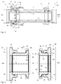
- FIG. 3 shows a schematic cross section of a bicycle component 1, which is designed here as a hub 108 and has a hub shell 2.
- the hub 108 is designed for receiving a thru axle, as for example in FIG. 5 is shown.
- a brake disk receptacle 7 is formed with a non-circular outer contour 7a.
- a Mounted adapter ring 15 can be mounted on the different brake discs.
- the adapter ring 15 is rotatably held on the non-circular outer contour 7a of the hub shell 2. In the axial direction, the adapter ring 15 is held by a corresponding stop on the hub shell and by a fixing ring 9, which is screwed with an external thread into an internal thread 8a on the fixing receptacle 8 of the hub shell.
- Both the fixing ring 9 and the adapter ring 15 may, but need not be, part of a sold hub 108. It is also possible and preferred to apply a standard brake disc directly to the brake disc holder 7, which is then firmly held in the axial direction by a fixing ring 9. In particular, the brake disk holder 7 is designed to receive a brake disk according to the "Centerlock" standard.
- Two bearing devices 3 and 4 are accommodated on the hub shell in order to rotatably support the hub shell 2 with respect to the thru-axle 91 still to be inserted.
- the outer rings of the bearing devices 3 and 4 are fixed axially inwardly at corresponding paragraphs in the hub shell 2.
- a spacer 16 is arranged, which here has the task to keep the storage facilities 3 and 4 to each other at a defined distance and further passes the clamping force occurring in the clamping of the hub.
- a radial movement of the spacer 16 is reduced by the O-rings 17 on the spacer 16 to a small degree, so that the thru axle 91 from FIG. 5 can be easily inserted into the interior of the bicycle component 1.
- an end stop 10 is provided which is formed in two parts and comprises a first stop component 20 and a second stop component 30.
- the end stop 10 serves to transfer the clamping forces from the outer stop 13 to the second stop component 30 here directly on the inner bearing ring 3b of the bearing device 3 via the inner stop 11 on the first stop component.
- the clamping forces are then transmitted further from the inner bearing ring 3b via the spacer 16 to the inner bearing ring of the bearing device 4, from where they are transferred to the end stop 60.
- the end stop 60 in turn consists of two stop components, namely a first stop component 70 and a second stop component 80, on which in turn an inner stop 62 and an outer stop 63 are formed.
- a force transmission component 18 is arranged between an end stop 10, 60 and the corresponding bearing means 3 and 4. It is also possible that between the two end stops 10, 60 and the corresponding storage facilities 3 and 4, a force transfer component 18 is arranged, as shown in dashed lines in Fig. 4 is shown. Then, an indirect force transfer from the corresponding end stop 10, 60 takes place on the bearing means 3, 4. In particularly preferred embodiments, only one force transfer component 18 or no force transfer component 18 is provided.
- FIG. 3 Marked in FIG. 3 is a free inner diameter 9a of the fixing ring 9. From the screw 9b extends as a fixing element 9c, an annular flange radially outwardly, whereby a brake disc or an adapter ring 15 are fixed.
- the free inner diameter 9a of the fixing ring 9 is smaller here than the outer diameter 3a of the bearing device 3 or 4.
- the largest inner diameter at the hub is found in the axial region 7b on the internal thread 8a of the Fixierfact.
- the outer diameter 14a of the outer stop surface 14 of the outer stop 13 is greater than the maximum inner diameter here 2a of the hub shell, which here is equal to the diameter of the internal thread 8a.
- the outer diameter 14a is thus larger than the free inner diameter 9a of the fixing ring 9 and also larger than the outer diameter 3a of the bearing means 3 and 4. This is possible because the end stops 10 and 60 are each formed in two parts, wherein the first stop component and the second stop component are releasably connected to each other by a friction element such as an O-ring 31 by hand.
- the second stop component 30 is axially withdrawn for replacement or, if appropriate, for mounting a brake disk, before the brake disk is mounted and fixed via a fixing ring 9. Following this, the second end stop 30 can simply be pushed onto the first end stop 20. A complete disassembly of the hub is not necessary.
- FIG. 4 shows enlarged representations of the end stops 10 and 60.
- Both end stops 10 and 60 each consist of a first stop component 20 and 70 and a second stop component 30 and 80.
- the second stop components 30 and 80 are identical, so that in total only three different Parts result.
- a radial flange 26 Disposed on the inner stop 11 of the first stop component 20 is a radial flange 26 which extends radially outward slightly spaced from the axially inner end of the first stop component 20 to reliably effect frictional contact with the bearing means 3 or 4 or other components avoid. Otherwise, the first stop component essentially has a tubular portion 25.
- the second stopper component 30 also includes a tubular portion. At the outer end of the second stop component 30, the outer stop 13 extends radially outward with the outer stop surface 14. Overall, this results in an annular outer stop surface 14 with an outer diameter 14a, which is considerably larger than that Outer diameter at the radial flange 26 of the first stopper component 20th
- the first stopper component 20 and the second stopper component 30 overlap in an overlapping portion 21 in which a friction member 31 is disposed like an O-ring.
- the O-ring is arranged in a groove 34 in the second stop component 30.
- the force transmission in the clamping takes place here from the outer stop 13 on the frontal end of the tubular portion 25 through the first stop component 20 through to the inner stop 11, from where the clamping forces on the inner bearing ring 3b and the spacer 16 on the inner bearing ring Bearing device 4 are derived. From there, the clamping forces on the other end stop 60 are finally derived in the dropout.
- the sealing device 50 is formed here by the retaining ring 40 and the radial flange 26 of the first stopper component 20.
- the retaining ring 40 is inserted axially from the outside into the hub shell 2 and screwed in there or held by friction forces.
- a radially inwardly extending flange 41 is provided at the end facing the second stop component 30. Between the flanges 41 and 26 results in a thin gap, which provides a sealing gap of the sealing device 50 is available. The sealing gap is deflected several times, so that there is practically a labyrinth seal through the flanges 41 of the retaining ring 40 and the flange 26 of the first stop component 20.
- first flange 26 In the region 26a of the first flange 26 may also be provided a double flange, with which the sealing effect can be enhanced. In addition, if necessary, the weight of the first stopper component can be reduced somewhat.
- the end stop 60 is constructed accordingly, but here has a smaller axial length.
- the end stop 60 is provided at the second end 6 of the hub shell 2, where no brake disk 7 is present.
- the end stop 60 has a first stopper component 70 and a second stopper component 80, which is here identical to the second stop component 30 of the end stop 10.
- the two stop components 70 and 80 are held together captive via an O-ring 31.
- the first stop component 70 of the end stop 60 is held, like the first stop component 20 of the end stop 10, by the retaining ring 40 in the interior of the hub shell 2. Therefore, even when removing the second stopper component 30, 80, the respective first stopper component 20, 70 is retained within the hub shell 2.
- the second stopper component 80 includes a tubular portion. At the outer end, the second stop component 80 on the outer stop 63 with the radially outwardly projecting stop surface 64.
- the annular outer stop surface 64 with an outer diameter 64a is larger than the outer diameter at the radial flange 76 or optionally at a double flange of the first stop component 70th
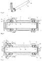
- FIG. 5 shows a schematic representation of an Achs worn 90, which is designed here as a plug-in axis 91 and at one end a thread 94 and at the other end comprises a clamping lever 93.
- FIG. 6 shows a variant of a bicycle component 1, which is constructed similar to the bicycle component according to FIG. 3 , Also the bicycle component 1 after FIG. 6 is designed to receive a thru-axle 91.
- the storage facilities 3 and 4 mounted on an axle 95, which is provided with two outwardly projecting radial paragraphs 97.
- the paragraphs 97 form a spacer 16.
- the end stop 10 in turn consists of two stop components 20 and 30.
- the first stop component 20 here a double flange 27, whereby a sufficient sealing effect can be achieved.
- the first stopper components 20 are held here on friction elements such as O-rings on the axle 95, whereby the retaining rings 40 can be dispensed with. It is also possible to attach an additional retaining ring 40 so as to provide a total of three adjacent flanges as a sealing device 50.
- the end stop 60 here consists of a single component, in which the stopper component 70 and 80 are integrated. At the end stop a double flange 27 is also provided here. The end stop 60 is also held on the axle part 95 via a friction element 31, such as an O-ring.
- end stops 10 and 60 can also be formed in two parts.
- FIG. 7 shows a further embodiment, which is intended for use with a quick release.
- the end stops 10 and 60 have axially outwardly each a stub axle 96 which serves for insertion into a dropout of a bicycle frame or a fork. Subsequently, a quick release can be carried out and the hub can be fixed to the frame via a quick release.
- an axle 95 is again provided, which can extend over the entire length of the hub shell 2 and on which the first stop components 20 and 70 are pushed. It is possible to use O-rings for frictional engagement with the axle 95. It is also possible to use retaining rings 40, which have a radially inwardly projecting flange 41 and thus reliably retain the first stop components 20 and 70.
- the spacer 16 between the bearings 3 and 4 may be integral the axle part or separately formed as indicated by the dashed line.
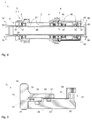
- FIG. 8 shows a variant of a running as a rear hub or a rear hub comprehensive bicycle component 1.
- the illustrated in section bicycle component 1 after FIG. 8 basically has similar or identical components as the bicycle component 1 after FIG. 6 ,
- the bicycle component 1 after FIG. 8 is for the inclusion of a thru axle 91 (see. Fig. 5 ), but may also be provided with adapted end stops 10 and 60 for use with conventional quick releases.
- adapted end stops 10 and 60 can with Achsstummeln 96 analogous to the end stops after Fig. 7 be equipped and optionally also have double flanges.
- the illustrated rear hub has a hub shell 2 with spoke flanges formed or provided thereon for attachment of spokes.
- a disc brake receiver 7 is formed or fixed to the first end 5 of the hub shell 2.
- At the second end 6 of the rotor 45 is provided for receiving a sprocket assembly, not shown.
- the rotor 45 is rotatably supported by two axially spaced bearings 46 on the axle 95. Between the bearings 46, a sleeve-shaped spacer is located. The sleeve-shaped spacer holds the inner bearing rings of the bearing 46 at a defined distance from each other and transmits the axial force.
- designed as a toothed disk freewheel 47 is provided.
- the freewheel comprises two toothed disks, which are preloaded from one side to the other via one or two spring devices, so that the axial toothings of the two toothed disks of the freewheel 47 intermesh in the ground state.
- the axle part 95 has two radially outwardly projecting shoulders 97, against which the inner bearing shells of the bearings 3 and 4 rest axially inwards.
- the end stops 10 and 60 of in FIG. 8 shown bicycle component 1 each consist in turn of two stop components.
- the first stop components 20 and 70 may each have a double flange 27, whereby a sufficient sealing effect can be achieved.
- the first stop components 20 and 70 are held on the axle part 95 via friction elements 31, such as O-rings, whereby retaining rings 40 can be dispensed with.
- the first stop component 20 at the first end 5 is formed here practically only by the double flange 27 and the O-ring 31. It is also possible here to install an additional retaining ring 40 so as to provide a total of three adjacent flanges as a sealing device 50.
- a cross-hatched fastening ring 42 is shown here in the lower right-hand part, which serves to fasten a (standard) sprocket set (not shown here).
- the fastening ring 42 may, for. B. are screwed into an internal thread at the outer end of the rotor. Then there is not the full inside diameter of the rotor available.
- a two-piece end stop 60 with the stopper components 70 and 80 allows a significant enlarged outer stop surface 64 also on the rotor side of the hub, without having to completely dismantle the end stop during assembly of the rotor.
- the outer diameter of the outer stop surface 64 may be selected to be greater than the remaining inner diameter 48 of the mounting ring 42 and may also be larger than the inner diameter of the internal thread of the rotor for screwing the mounting ring 42, as in FIG. 8 you can see.
- the mounting ring 42 may have an inwardly projecting flange (indicated diagonally hatched) for even further seal, if provided for a corresponding mounting and dismounting possibility of the mounting ring 42.
- the further details are in accordance with the embodiments according to FIG. 6 or FIG. 3 essentially coincide.
- FIG. 9 shows a schematic enlarged cross section of an end stop 10 in different embodiments.
- the first stop component 20 has a tubular portion 26 with two stepped diameter portions 22 and 23 and here a double flange 27 in the vicinity of the inner stopper 11th
- the retaining ring 40 Shown is also the retaining ring 40 with the radially inwardly projecting flange 41.
- the retaining ring 40 has an external thread, with which it is screwed into the hub shell 2.
- the friction element 31 for the captive connection of the abutment components 20 and 30 in the second diameter section 23 is preferable to provide the friction element 31 for the captive connection of the abutment components 20 and 30 in the second diameter section 23 with a larger outer diameter.
- the available wall thickness for transmitting the clamping forces in the diameter section 22 is not reduced.
- the friction ring 31 in the first diameter section 32 of the second stop component 30, as it is likewise shown by dashed lines.
- first diameter section 32 there is a greater wall thickness than in the second diameter section 33.
- the outer stop 13 with the outer stop surface 14 has a larger outer diameter than the first stop component 20th
- the invention provides an advantageous bicycle component 1 with end stops 10 and 60, with which a bicycle 100 can be produced with advantageous properties.
Landscapes
- Engineering & Computer Science (AREA)
- Mechanical Engineering (AREA)
- Axle Suspensions And Sidecars For Cycles (AREA)
- Mounting Of Bearings Or Others (AREA)
Applications Claiming Priority (1)
| Application Number | Priority Date | Filing Date | Title |
|---|---|---|---|
| DE102014117145.4A DE102014117145A1 (de) | 2014-11-24 | 2014-11-24 | Fahrradkomponente mit einem Endanschlag und Endanschlag |
Publications (2)
| Publication Number | Publication Date |
|---|---|
| EP3023325A1 true EP3023325A1 (fr) | 2016-05-25 |
| EP3023325B1 EP3023325B1 (fr) | 2020-01-01 |
Family
ID=54705401
Family Applications (1)
| Application Number | Title | Priority Date | Filing Date |
|---|---|---|---|
| EP15196001.0A Active EP3023325B1 (fr) | 2014-11-24 | 2015-11-24 | Composant de vélo comprenant une butée et butée |
Country Status (3)
| Country | Link |
|---|---|
| US (2) | US10065452B2 (fr) |
| EP (1) | EP3023325B1 (fr) |
| DE (1) | DE102014117145A1 (fr) |
Cited By (1)
| Publication number | Priority date | Publication date | Assignee | Title |
|---|---|---|---|---|
| US12138958B2 (en) | 2021-12-22 | 2024-11-12 | Giant Manufacturing Co., Ltd. | Hub structure and hub for a bicycle |
Families Citing this family (9)
| Publication number | Priority date | Publication date | Assignee | Title |
|---|---|---|---|---|
| US20160039491A1 (en) * | 2014-08-06 | 2016-02-11 | Angelo Morelli | Bicycle with disc brakes removable from the relative wheel |
| DE102016003725A1 (de) * | 2016-03-24 | 2017-09-28 | MG Components GmbH & Co. KG | Hinterradnabe mit Stirnradverzahnung für ein Fahrrad |
| US10933691B2 (en) | 2017-07-26 | 2021-03-02 | Dt Swiss Inc. | Hub, in particular for bicycles |
| US10442245B2 (en) * | 2016-07-26 | 2019-10-15 | Dt Swiss Inc. | Hub, in particular for bicycles |
| DE102017116948A1 (de) | 2016-07-26 | 2018-02-01 | Dt Swiss Ag | Nabe insbesondere für Fahrräder |
| US10625540B2 (en) | 2017-07-26 | 2020-04-21 | Dt Swiss Inc. | Hub, in particular for bicycles |
| US10995806B2 (en) | 2017-07-26 | 2021-05-04 | Dt Swiss Inc. | Hub, in particular for bicycles |
| US11919333B2 (en) * | 2021-03-01 | 2024-03-05 | Shimano Inc. | Hub for human-powered vehicle |
| US12151780B2 (en) * | 2021-06-28 | 2024-11-26 | Fox Factory, Inc. | Seal structures |
Citations (2)
| Publication number | Priority date | Publication date | Assignee | Title |
|---|---|---|---|---|
| DE4120209A1 (de) * | 1989-12-21 | 1992-12-24 | Hubert Coenen | Zweirad fuer den saalradsport unter verwendung einer al. nabe mit grossem huelsendurchmesser |
| US7581795B1 (en) * | 2007-05-16 | 2009-09-01 | Chosen Co., Ltd. | Bicycle frame whose bearings will not be pressed |
Family Cites Families (16)
| Publication number | Priority date | Publication date | Assignee | Title |
|---|---|---|---|---|
| US5499875A (en) * | 1994-12-23 | 1996-03-19 | Fu; Chueh-Kuo | Bicycle hub assembly |
| US6533364B2 (en) * | 2001-04-16 | 2003-03-18 | Paul Lew | Wheel hub |
| US7059686B2 (en) * | 2003-01-22 | 2006-06-13 | Shimano Inc. | Bicycle hub |
| US6854569B2 (en) * | 2003-03-18 | 2005-02-15 | Kun Teng Industry Co., Ltd. | Brakable wheel hub device |
| JP2005308059A (ja) * | 2004-04-20 | 2005-11-04 | Shimano Inc | 自転車用ディスクブレーキロータ組立体 |
| DE602004011217T2 (de) * | 2004-08-26 | 2009-01-08 | Chin Haur Industry Co., Ltd., Ta-Liao Hsiang | Hinterradnabenanordnung für ein Fahrrad |
| JP4610532B2 (ja) * | 2006-02-17 | 2011-01-12 | 株式会社シマノ | 自転車用ディスクブレーキハブ |
| US20070241608A1 (en) * | 2006-04-13 | 2007-10-18 | Kun Teng Industry Co., Ltd. | Bicycle hub and assembly of bicycle hub and spokes |
| TWM298526U (en) * | 2006-04-28 | 2006-10-01 | Chosen Co Ltd | Improved coupling device of hub and transmission sprocket |
| US7562755B2 (en) * | 2006-07-07 | 2009-07-21 | Dt Swiss, Inc. | Rear wheel hub, in particular for bicycles |
| DE102008013938A1 (de) * | 2008-03-12 | 2009-09-17 | Dt Swiss Ag | Fahrradkomponente |
| DE102008021803A1 (de) | 2008-04-30 | 2009-11-05 | Dt Swiss Ag | Nabe, insbesondere für Fahrräder |
| DE102010024474A1 (de) * | 2010-06-21 | 2011-12-22 | Dt Swiss Ag | Achssystem für ein Zweirad |
| DE102011013536A1 (de) * | 2011-03-10 | 2012-09-13 | Dt Swiss Ag | Nabe für ein Fahrrad |
| DE102011110496A1 (de) * | 2011-08-17 | 2013-02-21 | Dt Swiss Ag | Fahrradkomponente und Verfahren zur Montage einer Fahrradkomponente |
| US9174487B2 (en) * | 2012-07-10 | 2015-11-03 | Joy Industrial Co., Ltd. | Bicycle rear wheel hub assembly |
-
2014
- 2014-11-24 DE DE102014117145.4A patent/DE102014117145A1/de not_active Withdrawn
-
2015
- 2015-11-24 US US14/950,090 patent/US10065452B2/en active Active
- 2015-11-24 EP EP15196001.0A patent/EP3023325B1/fr active Active
-
2018
- 2018-08-03 US US16/054,186 patent/US10882355B2/en active Active
Patent Citations (2)
| Publication number | Priority date | Publication date | Assignee | Title |
|---|---|---|---|---|
| DE4120209A1 (de) * | 1989-12-21 | 1992-12-24 | Hubert Coenen | Zweirad fuer den saalradsport unter verwendung einer al. nabe mit grossem huelsendurchmesser |
| US7581795B1 (en) * | 2007-05-16 | 2009-09-01 | Chosen Co., Ltd. | Bicycle frame whose bearings will not be pressed |
Cited By (1)
| Publication number | Priority date | Publication date | Assignee | Title |
|---|---|---|---|---|
| US12138958B2 (en) | 2021-12-22 | 2024-11-12 | Giant Manufacturing Co., Ltd. | Hub structure and hub for a bicycle |
Also Published As
| Publication number | Publication date |
|---|---|
| US20160144661A1 (en) | 2016-05-26 |
| EP3023325B1 (fr) | 2020-01-01 |
| US20180339551A1 (en) | 2018-11-29 |
| US10065452B2 (en) | 2018-09-04 |
| DE102014117145A1 (de) | 2016-05-25 |
| US10882355B2 (en) | 2021-01-05 |
Similar Documents
| Publication | Publication Date | Title |
|---|---|---|
| EP3023325B1 (fr) | Composant de vélo comprenant une butée et butée | |
| DE102012017115B4 (de) | Fahrradvorderradnabe mit Torsionsrohr | |
| EP3275692B1 (fr) | Moyeu, en particulier pour vélos | |
| EP2497652B1 (fr) | Moyeu pour un vélo | |
| EP3590815B1 (fr) | Composant de bicyclette pour une bicyclette entraînée au moins partiellement par la puissance musculaire | |
| EP2100806B1 (fr) | Composant de bicyclette | |
| DE102012016608B4 (de) | Antriebsnabe | |
| EP2559567A2 (fr) | Composant de vélo et procédé de montage d'un composant de vélo | |
| EP1897701B1 (fr) | Roue système de fixation de rayons, en particulier pour vélos | |
| DE3922858C2 (fr) | ||
| EP1084045B1 (fr) | Moyeu destine a des bicyclettes | |
| EP2221191A1 (fr) | Composant de moyeu de vélo doté d'un axe creux en matériau composite renforcé en fibres et doté d'un rotor comportant une dentelure frontale | |
| EP2987713A2 (fr) | Dispositif de serrage rapide | |
| EP3862194B1 (fr) | Moyeu, en particulier pour bicyclettes | |
| EP3517316A1 (fr) | Moyeu | |
| EP3275694B1 (fr) | Moyeu, en particulier pour vélos | |
| DE102010024473A1 (de) | Achssystem für ein Zweirad | |
| DE102010024474A1 (de) | Achssystem für ein Zweirad | |
| DE102010033454B4 (de) | Radnabe | |
| DE102011111487A1 (de) | Nabe | |
| DE102007026821B4 (de) | Nabe, insbesondere für Fahrräder und dergleichen | |
| WO2018001726A1 (fr) | Ensemble d'extrémité d'axe comprenant une unité moyeu de roue et un frein de roue | |
| DE102007057226B4 (de) | Radkopf für eine Achse eines Kraftwagens | |
| DE102019002629A1 (de) | Fahrzeugbremse | |
| DE102022129554A1 (de) | Nabe insbesondere für Fahrräder |
Legal Events
| Date | Code | Title | Description |
|---|---|---|---|
| AK | Designated contracting states |
Kind code of ref document: A1 Designated state(s): AL AT BE BG CH CY CZ DE DK EE ES FI FR GB GR HR HU IE IS IT LI LT LU LV MC MK MT NL NO PL PT RO RS SE SI SK SM TR |
|
| AX | Request for extension of the european patent |
Extension state: BA ME |
|
| PUAI | Public reference made under article 153(3) epc to a published international application that has entered the european phase |
Free format text: ORIGINAL CODE: 0009012 |
|
| STAA | Information on the status of an ep patent application or granted ep patent |
Free format text: STATUS: REQUEST FOR EXAMINATION WAS MADE |
|
| 17P | Request for examination filed |
Effective date: 20161027 |
|
| RBV | Designated contracting states (corrected) |
Designated state(s): AL AT BE BG CH CY CZ DE DK EE ES FI FR GB GR HR HU IE IS IT LI LT LU LV MC MK MT NL NO PL PT RO RS SE SI SK SM TR |
|
| STAA | Information on the status of an ep patent application or granted ep patent |
Free format text: STATUS: EXAMINATION IS IN PROGRESS |
|
| 17Q | First examination report despatched |
Effective date: 20171121 |
|
| GRAP | Despatch of communication of intention to grant a patent |
Free format text: ORIGINAL CODE: EPIDOSNIGR1 |
|
| STAA | Information on the status of an ep patent application or granted ep patent |
Free format text: STATUS: GRANT OF PATENT IS INTENDED |
|
| INTG | Intention to grant announced |
Effective date: 20190711 |
|
| GRAS | Grant fee paid |
Free format text: ORIGINAL CODE: EPIDOSNIGR3 |
|
| GRAA | (expected) grant |
Free format text: ORIGINAL CODE: 0009210 |
|
| STAA | Information on the status of an ep patent application or granted ep patent |
Free format text: STATUS: THE PATENT HAS BEEN GRANTED |
|
| AK | Designated contracting states |
Kind code of ref document: B1 Designated state(s): AL AT BE BG CH CY CZ DE DK EE ES FI FR GB GR HR HU IE IS IT LI LT LU LV MC MK MT NL NO PL PT RO RS SE SI SK SM TR |
|
| REG | Reference to a national code |
Ref country code: GB Ref legal event code: FG4D Free format text: NOT ENGLISH |
|
| REG | Reference to a national code |
Ref country code: CH Ref legal event code: EP Ref country code: AT Ref legal event code: REF Ref document number: 1219468 Country of ref document: AT Kind code of ref document: T Effective date: 20200115 |
|
| REG | Reference to a national code |
Ref country code: DE Ref legal event code: R096 Ref document number: 502015011380 Country of ref document: DE |
|
| REG | Reference to a national code |
Ref country code: IE Ref legal event code: FG4D Free format text: LANGUAGE OF EP DOCUMENT: GERMAN |
|
| REG | Reference to a national code |
Ref country code: NL Ref legal event code: MP Effective date: 20200101 |
|
| REG | Reference to a national code |
Ref country code: LT Ref legal event code: MG4D |
|
| PG25 | Lapsed in a contracting state [announced via postgrant information from national office to epo] |
Ref country code: LT Free format text: LAPSE BECAUSE OF FAILURE TO SUBMIT A TRANSLATION OF THE DESCRIPTION OR TO PAY THE FEE WITHIN THE PRESCRIBED TIME-LIMIT Effective date: 20200101 Ref country code: NO Free format text: LAPSE BECAUSE OF FAILURE TO SUBMIT A TRANSLATION OF THE DESCRIPTION OR TO PAY THE FEE WITHIN THE PRESCRIBED TIME-LIMIT Effective date: 20200401 Ref country code: FI Free format text: LAPSE BECAUSE OF FAILURE TO SUBMIT A TRANSLATION OF THE DESCRIPTION OR TO PAY THE FEE WITHIN THE PRESCRIBED TIME-LIMIT Effective date: 20200101 Ref country code: RS Free format text: LAPSE BECAUSE OF FAILURE TO SUBMIT A TRANSLATION OF THE DESCRIPTION OR TO PAY THE FEE WITHIN THE PRESCRIBED TIME-LIMIT Effective date: 20200101 Ref country code: CZ Free format text: LAPSE BECAUSE OF FAILURE TO SUBMIT A TRANSLATION OF THE DESCRIPTION OR TO PAY THE FEE WITHIN THE PRESCRIBED TIME-LIMIT Effective date: 20200101 Ref country code: PT Free format text: LAPSE BECAUSE OF FAILURE TO SUBMIT A TRANSLATION OF THE DESCRIPTION OR TO PAY THE FEE WITHIN THE PRESCRIBED TIME-LIMIT Effective date: 20200527 Ref country code: NL Free format text: LAPSE BECAUSE OF FAILURE TO SUBMIT A TRANSLATION OF THE DESCRIPTION OR TO PAY THE FEE WITHIN THE PRESCRIBED TIME-LIMIT Effective date: 20200101 |
|
| PG25 | Lapsed in a contracting state [announced via postgrant information from national office to epo] |
Ref country code: HR Free format text: LAPSE BECAUSE OF FAILURE TO SUBMIT A TRANSLATION OF THE DESCRIPTION OR TO PAY THE FEE WITHIN THE PRESCRIBED TIME-LIMIT Effective date: 20200101 Ref country code: LV Free format text: LAPSE BECAUSE OF FAILURE TO SUBMIT A TRANSLATION OF THE DESCRIPTION OR TO PAY THE FEE WITHIN THE PRESCRIBED TIME-LIMIT Effective date: 20200101 Ref country code: SE Free format text: LAPSE BECAUSE OF FAILURE TO SUBMIT A TRANSLATION OF THE DESCRIPTION OR TO PAY THE FEE WITHIN THE PRESCRIBED TIME-LIMIT Effective date: 20200101 Ref country code: BG Free format text: LAPSE BECAUSE OF FAILURE TO SUBMIT A TRANSLATION OF THE DESCRIPTION OR TO PAY THE FEE WITHIN THE PRESCRIBED TIME-LIMIT Effective date: 20200401 Ref country code: IS Free format text: LAPSE BECAUSE OF FAILURE TO SUBMIT A TRANSLATION OF THE DESCRIPTION OR TO PAY THE FEE WITHIN THE PRESCRIBED TIME-LIMIT Effective date: 20200501 Ref country code: GR Free format text: LAPSE BECAUSE OF FAILURE TO SUBMIT A TRANSLATION OF THE DESCRIPTION OR TO PAY THE FEE WITHIN THE PRESCRIBED TIME-LIMIT Effective date: 20200402 |
|
| REG | Reference to a national code |
Ref country code: DE Ref legal event code: R097 Ref document number: 502015011380 Country of ref document: DE |
|
| PG25 | Lapsed in a contracting state [announced via postgrant information from national office to epo] |
Ref country code: SK Free format text: LAPSE BECAUSE OF FAILURE TO SUBMIT A TRANSLATION OF THE DESCRIPTION OR TO PAY THE FEE WITHIN THE PRESCRIBED TIME-LIMIT Effective date: 20200101 Ref country code: DK Free format text: LAPSE BECAUSE OF FAILURE TO SUBMIT A TRANSLATION OF THE DESCRIPTION OR TO PAY THE FEE WITHIN THE PRESCRIBED TIME-LIMIT Effective date: 20200101 Ref country code: SM Free format text: LAPSE BECAUSE OF FAILURE TO SUBMIT A TRANSLATION OF THE DESCRIPTION OR TO PAY THE FEE WITHIN THE PRESCRIBED TIME-LIMIT Effective date: 20200101 Ref country code: ES Free format text: LAPSE BECAUSE OF FAILURE TO SUBMIT A TRANSLATION OF THE DESCRIPTION OR TO PAY THE FEE WITHIN THE PRESCRIBED TIME-LIMIT Effective date: 20200101 Ref country code: EE Free format text: LAPSE BECAUSE OF FAILURE TO SUBMIT A TRANSLATION OF THE DESCRIPTION OR TO PAY THE FEE WITHIN THE PRESCRIBED TIME-LIMIT Effective date: 20200101 Ref country code: RO Free format text: LAPSE BECAUSE OF FAILURE TO SUBMIT A TRANSLATION OF THE DESCRIPTION OR TO PAY THE FEE WITHIN THE PRESCRIBED TIME-LIMIT Effective date: 20200101 |
|
| PLBE | No opposition filed within time limit |
Free format text: ORIGINAL CODE: 0009261 |
|
| STAA | Information on the status of an ep patent application or granted ep patent |
Free format text: STATUS: NO OPPOSITION FILED WITHIN TIME LIMIT |
|
| 26N | No opposition filed |
Effective date: 20201002 |
|
| PG25 | Lapsed in a contracting state [announced via postgrant information from national office to epo] |
Ref country code: IT Free format text: LAPSE BECAUSE OF FAILURE TO SUBMIT A TRANSLATION OF THE DESCRIPTION OR TO PAY THE FEE WITHIN THE PRESCRIBED TIME-LIMIT Effective date: 20200101 |
|
| PG25 | Lapsed in a contracting state [announced via postgrant information from national office to epo] |
Ref country code: PL Free format text: LAPSE BECAUSE OF FAILURE TO SUBMIT A TRANSLATION OF THE DESCRIPTION OR TO PAY THE FEE WITHIN THE PRESCRIBED TIME-LIMIT Effective date: 20200101 Ref country code: SI Free format text: LAPSE BECAUSE OF FAILURE TO SUBMIT A TRANSLATION OF THE DESCRIPTION OR TO PAY THE FEE WITHIN THE PRESCRIBED TIME-LIMIT Effective date: 20200101 |
|
| PG25 | Lapsed in a contracting state [announced via postgrant information from national office to epo] |
Ref country code: MC Free format text: LAPSE BECAUSE OF FAILURE TO SUBMIT A TRANSLATION OF THE DESCRIPTION OR TO PAY THE FEE WITHIN THE PRESCRIBED TIME-LIMIT Effective date: 20200101 |
|
| REG | Reference to a national code |
Ref country code: CH Ref legal event code: PL |
|
| GBPC | Gb: european patent ceased through non-payment of renewal fee |
Effective date: 20201124 |
|
| PG25 | Lapsed in a contracting state [announced via postgrant information from national office to epo] |
Ref country code: LU Free format text: LAPSE BECAUSE OF NON-PAYMENT OF DUE FEES Effective date: 20201124 |
|
| REG | Reference to a national code |
Ref country code: BE Ref legal event code: MM Effective date: 20201130 |
|
| PG25 | Lapsed in a contracting state [announced via postgrant information from national office to epo] |
Ref country code: CH Free format text: LAPSE BECAUSE OF NON-PAYMENT OF DUE FEES Effective date: 20201130 Ref country code: LI Free format text: LAPSE BECAUSE OF NON-PAYMENT OF DUE FEES Effective date: 20201130 |
|
| PG25 | Lapsed in a contracting state [announced via postgrant information from national office to epo] |
Ref country code: IE Free format text: LAPSE BECAUSE OF NON-PAYMENT OF DUE FEES Effective date: 20201124 Ref country code: FR Free format text: LAPSE BECAUSE OF NON-PAYMENT OF DUE FEES Effective date: 20201130 |
|
| PG25 | Lapsed in a contracting state [announced via postgrant information from national office to epo] |
Ref country code: GB Free format text: LAPSE BECAUSE OF NON-PAYMENT OF DUE FEES Effective date: 20201124 |
|
| REG | Reference to a national code |
Ref country code: AT Ref legal event code: MM01 Ref document number: 1219468 Country of ref document: AT Kind code of ref document: T Effective date: 20201124 |
|
| PG25 | Lapsed in a contracting state [announced via postgrant information from national office to epo] |
Ref country code: AT Free format text: LAPSE BECAUSE OF NON-PAYMENT OF DUE FEES Effective date: 20201124 |
|
| PG25 | Lapsed in a contracting state [announced via postgrant information from national office to epo] |
Ref country code: TR Free format text: LAPSE BECAUSE OF FAILURE TO SUBMIT A TRANSLATION OF THE DESCRIPTION OR TO PAY THE FEE WITHIN THE PRESCRIBED TIME-LIMIT Effective date: 20200101 Ref country code: MT Free format text: LAPSE BECAUSE OF FAILURE TO SUBMIT A TRANSLATION OF THE DESCRIPTION OR TO PAY THE FEE WITHIN THE PRESCRIBED TIME-LIMIT Effective date: 20200101 Ref country code: CY Free format text: LAPSE BECAUSE OF FAILURE TO SUBMIT A TRANSLATION OF THE DESCRIPTION OR TO PAY THE FEE WITHIN THE PRESCRIBED TIME-LIMIT Effective date: 20200101 |
|
| PG25 | Lapsed in a contracting state [announced via postgrant information from national office to epo] |
Ref country code: MK Free format text: LAPSE BECAUSE OF FAILURE TO SUBMIT A TRANSLATION OF THE DESCRIPTION OR TO PAY THE FEE WITHIN THE PRESCRIBED TIME-LIMIT Effective date: 20200101 Ref country code: AL Free format text: LAPSE BECAUSE OF FAILURE TO SUBMIT A TRANSLATION OF THE DESCRIPTION OR TO PAY THE FEE WITHIN THE PRESCRIBED TIME-LIMIT Effective date: 20200101 |
|
| PG25 | Lapsed in a contracting state [announced via postgrant information from national office to epo] |
Ref country code: BE Free format text: LAPSE BECAUSE OF NON-PAYMENT OF DUE FEES Effective date: 20201130 |
|
| P01 | Opt-out of the competence of the unified patent court (upc) registered |
Effective date: 20230517 |
|
| PGFP | Annual fee paid to national office [announced via postgrant information from national office to epo] |
Ref country code: DE Payment date: 20251222 Year of fee payment: 11 |