EP3023599B1 - Verzweigte gleitdichtung - Google Patents
Verzweigte gleitdichtung Download PDFInfo
- Publication number
- EP3023599B1 EP3023599B1 EP15190414.1A EP15190414A EP3023599B1 EP 3023599 B1 EP3023599 B1 EP 3023599B1 EP 15190414 A EP15190414 A EP 15190414A EP 3023599 B1 EP3023599 B1 EP 3023599B1
- Authority
- EP
- European Patent Office
- Prior art keywords
- seal
- section
- seal section
- component
- contact
- Prior art date
- Legal status (The legal status is an assumption and is not a legal conclusion. Google has not performed a legal analysis and makes no representation as to the accuracy of the status listed.)
- Active
Links
Images




Classifications
-
- F—MECHANICAL ENGINEERING; LIGHTING; HEATING; WEAPONS; BLASTING
- F01—MACHINES OR ENGINES IN GENERAL; ENGINE PLANTS IN GENERAL; STEAM ENGINES
- F01D—NON-POSITIVE DISPLACEMENT MACHINES OR ENGINES, e.g. STEAM TURBINES
- F01D11/00—Preventing or minimising internal leakage of working-fluid, e.g. between stages
- F01D11/005—Sealing means between non relatively rotating elements
-
- F—MECHANICAL ENGINEERING; LIGHTING; HEATING; WEAPONS; BLASTING
- F01—MACHINES OR ENGINES IN GENERAL; ENGINE PLANTS IN GENERAL; STEAM ENGINES
- F01D—NON-POSITIVE DISPLACEMENT MACHINES OR ENGINES, e.g. STEAM TURBINES
- F01D11/00—Preventing or minimising internal leakage of working-fluid, e.g. between stages
- F01D11/003—Preventing or minimising internal leakage of working-fluid, e.g. between stages by packing rings; Mechanical seals
-
- F—MECHANICAL ENGINEERING; LIGHTING; HEATING; WEAPONS; BLASTING
- F02—COMBUSTION ENGINES; HOT-GAS OR COMBUSTION-PRODUCT ENGINE PLANTS
- F02C—GAS-TURBINE PLANTS; AIR INTAKES FOR JET-PROPULSION PLANTS; CONTROLLING FUEL SUPPLY IN AIR-BREATHING JET-PROPULSION PLANTS
- F02C7/00—Features, components parts, details or accessories, not provided for in, or of interest apart form groups F02C1/00 - F02C6/00; Air intakes for jet-propulsion plants
- F02C7/28—Arrangement of seals
-
- F—MECHANICAL ENGINEERING; LIGHTING; HEATING; WEAPONS; BLASTING
- F16—ENGINEERING ELEMENTS AND UNITS; GENERAL MEASURES FOR PRODUCING AND MAINTAINING EFFECTIVE FUNCTIONING OF MACHINES OR INSTALLATIONS; THERMAL INSULATION IN GENERAL
- F16J—PISTONS; CYLINDERS; SEALINGS
- F16J15/00—Sealings
- F16J15/02—Sealings between relatively-stationary surfaces
- F16J15/06—Sealings between relatively-stationary surfaces with solid packing compressed between sealing surfaces
- F16J15/08—Sealings between relatively-stationary surfaces with solid packing compressed between sealing surfaces with exclusively metal packing
- F16J15/0806—Sealings between relatively-stationary surfaces with solid packing compressed between sealing surfaces with exclusively metal packing characterised by material or surface treatment
-
- F—MECHANICAL ENGINEERING; LIGHTING; HEATING; WEAPONS; BLASTING
- F16—ENGINEERING ELEMENTS AND UNITS; GENERAL MEASURES FOR PRODUCING AND MAINTAINING EFFECTIVE FUNCTIONING OF MACHINES OR INSTALLATIONS; THERMAL INSULATION IN GENERAL
- F16J—PISTONS; CYLINDERS; SEALINGS
- F16J15/00—Sealings
- F16J15/02—Sealings between relatively-stationary surfaces
- F16J15/06—Sealings between relatively-stationary surfaces with solid packing compressed between sealing surfaces
- F16J15/08—Sealings between relatively-stationary surfaces with solid packing compressed between sealing surfaces with exclusively metal packing
- F16J15/0887—Sealings between relatively-stationary surfaces with solid packing compressed between sealing surfaces with exclusively metal packing the sealing effect being obtained by elastic deformation of the packing
-
- F—MECHANICAL ENGINEERING; LIGHTING; HEATING; WEAPONS; BLASTING
- F05—INDEXING SCHEMES RELATING TO ENGINES OR PUMPS IN VARIOUS SUBCLASSES OF CLASSES F01-F04
- F05D—INDEXING SCHEME FOR ASPECTS RELATING TO NON-POSITIVE-DISPLACEMENT MACHINES OR ENGINES, GAS-TURBINES OR JET-PROPULSION PLANTS
- F05D2220/00—Application
- F05D2220/30—Application in turbines
- F05D2220/32—Application in turbines in gas turbines
-
- F—MECHANICAL ENGINEERING; LIGHTING; HEATING; WEAPONS; BLASTING
- F05—INDEXING SCHEMES RELATING TO ENGINES OR PUMPS IN VARIOUS SUBCLASSES OF CLASSES F01-F04
- F05D—INDEXING SCHEME FOR ASPECTS RELATING TO NON-POSITIVE-DISPLACEMENT MACHINES OR ENGINES, GAS-TURBINES OR JET-PROPULSION PLANTS
- F05D2220/00—Application
- F05D2220/30—Application in turbines
- F05D2220/32—Application in turbines in gas turbines
- F05D2220/323—Application in turbines in gas turbines for aircraft propulsion, e.g. jet engines
-
- F—MECHANICAL ENGINEERING; LIGHTING; HEATING; WEAPONS; BLASTING
- F05—INDEXING SCHEMES RELATING TO ENGINES OR PUMPS IN VARIOUS SUBCLASSES OF CLASSES F01-F04
- F05D—INDEXING SCHEME FOR ASPECTS RELATING TO NON-POSITIVE-DISPLACEMENT MACHINES OR ENGINES, GAS-TURBINES OR JET-PROPULSION PLANTS
- F05D2240/00—Components
- F05D2240/55—Seals
-
- F—MECHANICAL ENGINEERING; LIGHTING; HEATING; WEAPONS; BLASTING
- F05—INDEXING SCHEMES RELATING TO ENGINES OR PUMPS IN VARIOUS SUBCLASSES OF CLASSES F01-F04
- F05D—INDEXING SCHEME FOR ASPECTS RELATING TO NON-POSITIVE-DISPLACEMENT MACHINES OR ENGINES, GAS-TURBINES OR JET-PROPULSION PLANTS
- F05D2260/00—Function
- F05D2260/30—Retaining components in desired mutual position
- F05D2260/38—Retaining components in desired mutual position by a spring, i.e. spring loaded or biased towards a certain position
-
- F—MECHANICAL ENGINEERING; LIGHTING; HEATING; WEAPONS; BLASTING
- F05—INDEXING SCHEMES RELATING TO ENGINES OR PUMPS IN VARIOUS SUBCLASSES OF CLASSES F01-F04
- F05D—INDEXING SCHEME FOR ASPECTS RELATING TO NON-POSITIVE-DISPLACEMENT MACHINES OR ENGINES, GAS-TURBINES OR JET-PROPULSION PLANTS
- F05D2300/00—Materials; Properties thereof
- F05D2300/10—Metals, alloys or intermetallic compounds
- F05D2300/17—Alloys
- F05D2300/176—Heat-stable alloys
-
- F—MECHANICAL ENGINEERING; LIGHTING; HEATING; WEAPONS; BLASTING
- F05—INDEXING SCHEMES RELATING TO ENGINES OR PUMPS IN VARIOUS SUBCLASSES OF CLASSES F01-F04
- F05D—INDEXING SCHEME FOR ASPECTS RELATING TO NON-POSITIVE-DISPLACEMENT MACHINES OR ENGINES, GAS-TURBINES OR JET-PROPULSION PLANTS
- F05D2300/00—Materials; Properties thereof
- F05D2300/60—Properties or characteristics given to material by treatment or manufacturing
- F05D2300/603—Composites; e.g. fibre-reinforced
- F05D2300/6033—Ceramic matrix composites [CMC]
-
- Y—GENERAL TAGGING OF NEW TECHNOLOGICAL DEVELOPMENTS; GENERAL TAGGING OF CROSS-SECTIONAL TECHNOLOGIES SPANNING OVER SEVERAL SECTIONS OF THE IPC; TECHNICAL SUBJECTS COVERED BY FORMER USPC CROSS-REFERENCE ART COLLECTIONS [XRACs] AND DIGESTS
- Y02—TECHNOLOGIES OR APPLICATIONS FOR MITIGATION OR ADAPTATION AGAINST CLIMATE CHANGE
- Y02T—CLIMATE CHANGE MITIGATION TECHNOLOGIES RELATED TO TRANSPORTATION
- Y02T50/00—Aeronautics or air transport
- Y02T50/60—Efficient propulsion technologies, e.g. for aircraft
Definitions
- the present disclosure is generally related to seals and, more specifically, to a sliding seal.
- Seals are used in many applications to prevent or limit the flow of a gas or liquid from one side of the seal to another side of the seal.
- seals are used in many areas within a gas turbine engine to seal the gas path of the engine.
- the performance of gas path seals affects engine component efficiency.
- the loss of secondary flow into the gas path of a turbine engine has a negative effect on engine fuel burn, performance/efficiency, and component life.
- a metal w-seal or a non-metallic rope seal are typical seals used to seal or limit secondary flow between segmented or full-hoop turbine components.
- exposure to significant relative deflections between adjacent components and/or elevated temperatures can preclude the use of these types of seals or cause them to fail prematurely.
- a w-seal will deform and become ineffective.
- Using a higher strength material improves deflection capability somewhat, but generally at the expense of limiting temperature capability.
- Wear resistance can be a problem as well in an environment of significant relative motion.
- a rope seal typically has high temperature capability but has even less flexibility.
- a prior art seal having the features of the preamble of claim 1, is disclosed in US 5078412 .
- a further such prior art seal is disclosed in US 2014/0225334 A1 .
- a prior art jet pipe assembly is disclosed in GB 2 385 643 A .
- the present invention provides a seal, as recited in claim 1.
- FIG. 1 schematically illustrates a gas turbine engine 20.
- the gas turbine engine 20 is disclosed herein as a two-spool turbofan that generally incorporates a fan section 22, a compressor section 24, a combustor section 26 and a turbine section 28.
- Alternative engines might include an augmentor section (not shown) among other systems or features.
- the fan section 22 drives air along a bypass flow path B in a bypass duct, while the compressor section 24 drives air along a core flow path C for compression and communication into the combustor section 26 then expansion through the turbine section 28.
- the exemplary engine 20 generally includes a low speed spool 30 and a high speed spool 32 mounted for rotation about an engine central longitudinal axis A relative to an engine static structure 36 via several bearing systems 38. It should be understood that various bearing systems 38 at various locations may alternatively or additionally be provided, and the location of bearing systems 38 may be varied as appropriate to the application.
- the low speed spool 30 generally includes an inner shaft 40 that interconnects a fan 42, a low pressure compressor 44 and a low pressure turbine 46.
- the inner shaft 40 is connected to the fan 42 through a speed change mechanism, which in exemplary gas turbine engine 20 is illustrated as a geared architecture 48 to drive the fan 42 at a lower speed than the low speed spool 30.
- the high speed spool 32 includes an outer shaft 50 that interconnects a high pressure compressor 52 and high pressure turbine 54.
- a combustor 56 is arranged in exemplary gas turbine 20 between the high pressure compressor 52 and the high pressure turbine 54.
- An engine static structure 36 is arranged generally between the high pressure turbine 54 and the low pressure turbine 46.
- the engine static structure 36 further supports bearing systems 38 in the turbine section 28.
- the inner shaft 40 and the outer shaft 50 are concentric and rotate via bearing systems 38 about the engine central longitudinal axis A which is collinear with their longitudinal axes.
- each of the positions of the fan section 22, compressor section 24, combustor section 26, turbine section 28, and fan drive gear system 48 may be varied.
- gear system 48 may be located aft of combustor section 26 or even aft of turbine section 28, and fan section 22 may be positioned forward or aft of the location of gear system 48.
- the engine 20 in one example is a high-bypass geared aircraft engine.
- the engine 20 bypass ratio is greater than about six (6:1), with an example embodiment being greater than about ten (10:1)
- the geared architecture 48 is an epicyclic gear train, such as a planetary gear system or other gear system, with a gear reduction ratio of greater than about 2.3
- the low pressure turbine 46 has a pressure ratio that is greater than about five.
- the engine 20 bypass ratio is greater than about ten (10:1)
- the fan diameter is significantly larger than that of the low pressure compressor 44
- the low pressure turbine 46 has a pressure ratio that is greater than about five (5:1).
- Low pressure turbine 46 pressure ratio is pressure measured prior to inlet of low pressure turbine 46 as related to the pressure at the outlet of the low pressure turbine 46 prior to an exhaust nozzle.
- the geared architecture 48 may be an epicycle gear train, such as a planetary gear system or other gear system, with a gear reduction ratio of greater than about 2.3:1. It should be understood, however, that the above parameters are only exemplary of one embodiment of a geared architecture engine and that the present invention is applicable to other gas turbine engines including direct drive turbofans.
- the fan section 22 of the engine 20 is designed for a particular flight condition -- typically cruise at about 0.8 Mach and about 2. IF 10,668 meters (35,000 feet) .
- the flight condition of 0.8 Mach and 10,668 meters (35,000 feet), with the engine at its best fuel consumption - also known as "bucket cruise Thrust Specific Fuel Consumption ('TSFC')" - is the industry standard parameter of lbm of fuel being burned divided by lbf of thrust the engine produces at that minimum point.
- "Low fan pressure ratio” is the pressure ratio across the fan blade alone, without a Fan Exit Guide Vane (“FEGV”) system.
- the low fan pressure ratio as disclosed herein according to one non-limiting embodiment is less than about 1.45.
- "Low corrected fan tip speed” is the actual fan tip speed in meters / sec (ft / sec) divided by an industry standard temperature correction of [(Tram °R) / (518.7 °R)] 0.5 In this equation °R corresponds to 5/9 Kelvin.
- the "Low corrected fan tip speed” as disclosed herein according to one non-limiting embodiment is less than about 350.5 m / sec (1150 ft / second).
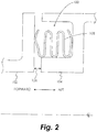
- FIG. 2 schematically illustrates a cross-sectional view of a seal cavity 100 formed by two axially-adjacent segmented or full-hoop turbine components 102 and 104 which may move axially, radially, and circumferentially relative to one another about an axial centerline of the turbine engine. This configuration is helpful to understand the present invention but does not form part of the present invention.
- a nominal design clearance 106 exists between the components 102 and 104.
- a w-seal 108 formed from a material appropriate to the anticipated operating conditions (e.g., deflection, temperature change, pressure, etc.) of the w-seal 108, such a nickel-base alloy to name just one non-limiting example.
- the design and material used in the construction of the w-seal 108 causes it to be deflected both forward and aft within the cavity 100, thereby causing it to seat against the components 102 and 104, even when the components 102 and 104 move relative to each other causing the clearance 106 to change.
- a w-seal 108 may deform, causing it to become ineffective and potentially liberate.
- FIG. 3 schematically illustrates a cross-sectional view of a seal cavity 200 formed by two axially-adjacent segmented or full hoop turbine components 202 and 204 which may move axially, radially, and circumferentially relative to one another about an axial centerline of the turbine engine.
- a nominal design clearance 206 exists between the components 202 and 204.
- Component 202 includes a surface 208 facing the seal cavity 200 and component 204 includes surfaces 210 and 211 facing the seal cavity 200.
- the seal 212 is formed from a first seal section 214 and a second seal section 216.
- the first seal section 214 is generally L-shaped in cross-section and includes a base 218 and a leg 220.
- the second seal section 216 is also generally L-shaped in cross-section and includes a base 222 and a leg 224.
- the bases 218, 222 are oriented substantially axially, while the legs 220, 224 are oriented substantially radially.
- the base 218 is supported by the base 222 in an embodiment, while in another embodiment the base 222 is supported by the base 218.
- the seal 212 may include a coating and/or a sheath to provide increased wear resistance.
- the seal section 214 includes a forward substantially rounded end 226 in contact with the surface 210 such that the seal section 214 contacts the surface 210 along a single circumferential line of contact.
- circumferential line of contact is intended to encompass lines that form a complete circle but which may have a gap formed therein, and includes lines with a nominal radial or axial thickness.
- the seal section 214 also includes an aft substantially rounded end 228 in contact with the seal section 216 (or the surface 211 in some embodiments) such that the seal section 214 contacts the seal section 216 (or the surface 211 in some embodiments) along a single circumferential line of contact.
- the seal section 216 includes an aft substantially rounded end 230 in contact with the surface 208 such that the seal section 216 contacts the surface 208 along a single circumferential line of contact.
- the seal section 216 also includes forward substantially rounded end 232 in contact with the surface 211 (or the seal section 214 in some embodiments) such that the seal section 216 contacts the surface 211 (or the seal section 214 in some embodiments) along a single circumferential line of contact.
- one or both of the seal sections 214, 216 include a plurality of spring tabs 234 spaced around their radially outer circumference.
- the spring tabs 234 are integrally formed with one or both of the seal sections 214, 216.
- the spring tabs 234 bias the seal sections 214, 216 axially away from one another, causing the seal section 214 to seat against the surface 210 of the component 204 and the seal section 216 to seat against the surface 208 of the component 202 when the cavity 200 is not pressurized. This mitigates risk of damage to the seal 212 in transportation and ensures that the seal 212 is instantly and positively pressurized/pressure-energized at engine start-up.
- a secondary flow cavity 238 Pressure in a secondary flow cavity 238 is transmitted to the seal cavity 200 through an opening defined by the components 202, 204.
- This pressure acts upon the surfaces of the seal sections 214, 216, thereby causing the leg 220 to seat against the surface 210 of the component 204, the leg 224 to seat against the surface 208 of the component 202, and the base 218 to seat against the base 222.
- the load applied by base 218 to base 222 helps base 222 to seat against the surface 211, thereby providing a secondary seal against flow that may leak past the leg 214/surface 210 interface, such as during engine start-up, for example. This prevents most or all of the secondary flow cavity 238 gases from reaching the design clearance 206 area and flow path.
- the seal sections 214, 216 are free to slide relative to one another in the axial direction (against the spring force of the spring tabs 234 when axially compressed) and circumferential direction, while the pressure forces acting upon the surfaces of the seal sections 214, 216 load the seal 212 so that it remains in contact with both components 202 and 204 as shown. Therefore, sealing is maintained while the components 202 and 204 and the components of the seal 212 move relative to one another. Because the seal sections 214, 216 slide with respect to one another and with respect to the components 202, 204, the seal 212 is not substantially deflected by the relative movement between the components 202 and 204 other than at the spring tabs 234.
- the spring tabs 234 push the seal sections 214 to remain in contact with the forward wall 210, and also push the seal section 216 to remain in contact with the aft wall 208 when the cavity 200 is not pressurized. This prevents the seal 212 from being damaged during transportation and installation, and also ensures that the seal 212 is instantly and positively pressurized/pressure-energized at engine start-up. In operation, the pressure loading on both seal sections 214, 216 is significant, because the contact points 226, 230 are well outboard, ensuring good sealing at the contact points 226, 230.
- the seal section 214 is split at one circumferential location to enable pressure to load the seal section 214 radially inward against the seal section 216.
- Splitting the seal section 216 also creates an additional sealing surface at the bottom of the seal cavity 200, as well as allowing the seal 212 to be packaged within a smaller radial design space. Leakage can be reduced significantly at the split location of each seal section 214, 216 by off-setting one split relative to the other, and further reduced by adding a sliding bridge to the cover the gap in the radially outer seal section 214.
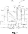
- FIG. 4 Another embodiment of the seal 212 is illustrated in FIG. 4 and designated as 212a.
- the seal section 214a does not comprise a base and leg as in the embodiment of FIG. 3 . Notwithstanding this, the seal section 214a seats against the surface 210 of the component 204 at rounded end 226a, and against the base 222 of the seal section 216a at rounded end 228a.
- the seal section 214a includes a plurality of spring tabs 234a spaced around their radially outer circumference.
- the spring tabs 234a are integrally formed with the seal section 214a.
- the spring tabs 234a contact the radially outer end 235 of the seal section 216a.
- the spring tabs 234a bias the seal sections 214a, 216a axially away from one another, causing the seal section 214a to seat against the surface 210 of the component 204 and the seal section 216a to seat against the surface 208 of the component 202 when the cavity 200 is not pressurized. This mitigates risk of damage to the seal 212a in transportation and ensures that the seal 212 is instantly and positively pressurized/pressure-energized at engine start-up.
- a first clip 240 is positioned axially forward of, and adjacent to, a spring tab 234a.
- the first clip 240 includes a first clip tab 242 that extends axially aft of the radially outer end 235 of the seal section 216a and wraps therearound, thereby maintaining the spring tab 234a and the radially outer end 235 of the seal section 216a in abutting relationship.
- the first clip 240 includes two radially inner legs 244 in abutting relationship with the spring tab 234a in an embodiment.
- a second clip 246 may then be installed with a portion of the second clip 246 abutting the forward surface of the radially inner legs 244 of the first clip 240, as well as abutting the aft surface of the spring tab 234a, thereby functioning to hold the first clip 240 in place.
- the seal 212a comprises a discrete assembly that may be handled and installed as a single piece.
- the first clip 240 and the second clip 246 may be formed from a polymer such as polyethylene that will vaporize at the normal operating temperature of the engine, to name one non-limiting example.
- the seal 212/212a Compared to the seal 108, the seal 212/212a exhibits increased resilience due to sliding of the seal components rather than flexing, and improved durability since the seal 212/212a is tolerant of additional axial deflection compared to the seal 108.
- the seal sections 214, 216 are not deflected (other than the spring tabs 234) as the components 202 and 204 move relative to each other during engine assembly and engine operation, which is beneficial because the seal sections 214, 216 can be made from a lower strength and/or thicker sheet material that may be lower cost, have higher temperature capability, be more manufacturable, and/or more wear-resistant. Additionally, the seal 212/212a is less susceptible to distortion or breakage, which can cause leakage of gas past the seal 212/212a and/or liberation of the seal. Finally, the seal 212/212a exhibits improved vibration tolerance due to friction damping.
Landscapes
- Engineering & Computer Science (AREA)
- General Engineering & Computer Science (AREA)
- Mechanical Engineering (AREA)
- Chemical & Material Sciences (AREA)
- Combustion & Propulsion (AREA)
- Gasket Seals (AREA)
Claims (14)
- Dichtung (212; 212a) zum Abdichten eines Raums, der durch eine erste und eine zweite benachbarte Komponente (102; 202, 104; 204) definiert ist, die um eine axiale Mittellinie (CL) angeordnet sind, wobei die Dichtung (212; 212a) Folgendes umfasst:einen ersten Dichtungsabschnitt (214; 214a);einen zweiten Dichtungsabschnitt (216; 216a);wobei der erste und der zweite Dichtungsabschnitt (214; 214a, 216; 216a) für einen dichtenden Eingriff mit der ersten und der zweiten Komponente (102; 202, 104; 204) konfiguriert sind und für eine Bewegung relativ zueinander konfiguriert sind; und eine oder mehrere Federlaschen (234; 234a), die sich von dem ersten Dichtungsabschnitt (214; 214a) und/oder dem zweiten Dichtungsabschnitt (216; 216a) aus erstrecken und einstückig mit diesen ausgebildet sind, zwischen dem ersten und dem zweiten Dichtungsabschnitt (214; 214a, 216; 216a) angeordnet sind und betreibbar sind, um den ersten Dichtungsabschnitt (214; 214a) und den zweiten Dichtungsabschnitt (216; 216a) voneinander weg vorzuspannen;wobeider erste Dichtungsabschnitt (214; 214a) ein erstes im Wesentlichen abgerundetes Ende (226; 226a) umfasst, das entlang einer ersten einzelnen umlaufenden Berührungslinie mit der ersten Komponente (204) in Berührung steht; dadurch gekennzeichnet, dassder zweite Dichtungsabschnitt (216; 216a) ein zweites im Wesentlichen abgerundetes Ende (230) umfasst, das entlang einer zweiten einzelnen umlaufenden Berührungslinie mit der zweiten Komponente (202) in Berührung steht.
- Dichtung (212) nach Anspruch 1, wobei:der erste Dichtungsabschnitt (214) eine erste Basis (218) und einen ersten Zweig (220), der sich von der ersten Basis (218) aus erstreckt, beinhaltet; undder zweite Dichtungsabschnitt (216) eine zweite Basis (222) und einen zweiten Zweig (224), der sich von der zweiten Basis (222) aus erstreckt, beinhaltet.
- Dichtung (212) nach Anspruch 2, wobei der erste Dichtungsabschnitt (214) und der zweite Dichtungsabschnitt (216) einen im Wesentlichen L-förmigen Querschnitt aufweisen.
- Dichtung (212) nach Anspruch 2 oder 3, wobei:die erste Basis (218) und die zweite Basis (222) im Wesentlichen axial ausgerichtet sind; undder erste Zweig (220) und der zweite Zweig (224) im Wesentlichen radial ausgerichtet sind.
- Dichtung (212) nach Anspruch 2, 3 oder 4, wobei die erste Basis (218) von der zweiten Basis (222) gestützt wird.
- Dichtung (212; 212a) nach einem der vorhergehenden Ansprüche, wobei die Dichtung (212; 212a) aus einem Material ausgebildet ist, das aus einer hitzebeständigen Metalllegierung, einem hitzebeständigen Keramikfasermaterial und einem hitzebeständigen Keramikfaserverbundstoff oder einer Kombination aus zwei oder mehr einer hitzebeständigen Metalllegierung, eines hitzebeständigen Keramikfasermaterials und eines hitzebeständigen Keramikfaserverbundstoffs ausgewählt ist.
- Dichtung (212; 212a) nach einem der vorhergehenden Ansprüche, ferner umfassend:eine Beschichtung, die zumindest auf einen Teil jedes des ersten und des zweiten Dichtungsabschnitts (214; 214a, 216; 216a) aufgetragen ist; und/odereine Hülse, die zumindest einen Teil jedes des ersten und des zweiten Dichtungsabschnitts (214; 214a, 216; 216a) bedeckt.
- Dichtung (212; 212a) nach einem der vorhergehenden Ansprüche, wobei:
der erste und der zweite Dichtungsabschnitt (214; 214a, 216; 216a) im Wesentlichen ringförmig sind. - Dichtung nach Anspruch 8, wobei der erste Dichtungsabschnitt (214; 214a) an einer ersten Umfangsstelle unterteilt ist, um eine erste Lücke zwischen gegenüberliegenden Enden des ersten Dichtungsabschnitts (214; 214a) zu definieren, und der zweite Dichtungsabschnitt (216; 216a) an einer zweiten Umfangsstelle unterteilt ist, um eine zweite Lücke zwischen gegenüberliegenden Enden des zweiten Dichtungsabschnitts (216; 216a) zu definieren.
- Dichtung nach Anspruch 9, ferner umfassend eine Überbrückungsdichtung, die benachbart zu dem ersten und dem zweiten Dichtungsabschnitt (214; 214a, 216; 216a) angeordnet ist und die erste und die zweite Lücke zumindest teilweise bedeckt.
- Dichtung (212; 212a) nach einem der vorhergehenden Ansprüche, wobei:der erste Dichtungsabschnitt (214; 214a) ein drittes im Wesentlichen abgerundetes Ende (228; 228a) umfasst, das entlang einer dritten einzelnen umlaufenden Berührungslinie mit dem zweiten Dichtungsabschnitt (216; 216a) in Berührung steht; undder zweite Dichtungsabschnitt (216; 216a) ein viertes im Wesentlichen abgerundetes Ende (232) umfasst, das entlang einer vierten einzelnen umlaufenden Berührungslinie mit der ersten Komponente (204) in Berührung steht.
- Dichtung (212; 212a) nach einem der vorhergehenden Ansprüche, wobei die eine oder die mehreren Federlaschen (234; 234a) den ersten Dichtungsabschnitt (214; 214a) und den zweiten Dichtungsabschnitt (216; 216a) in einer axialen Richtung voneinander weg vorspannen.
- Dichtung (212a) nach einem der vorhergehenden Ansprüche, ferner umfassend eine Klemme (246), die eine oder mehrere der Federlaschen (234a) in einer anliegenden Beziehung mit dem zweiten Dichtungsabschnitt (216a) festhält, wobei optional die Klemme (246) ein Material umfasst, das bei einer normalen Betriebstemperatur der ersten und der zweiten Komponente (204; 202) verdampft.
- System, umfassend:eine erste Komponente (204), die eine erste Fläche (210) beinhaltet;eine zweite Komponente (202), die eine zweite Fläche (208) beinhaltet, wobei die zweite Komponente (202) benachbart zu der ersten Komponente (204) angeordnet ist und einen Dichtungshohlraum (238) dazwischen definiert;wobei die erste und die zweite Komponente (204; 202) um eine axiale Mittellinie (CL) angeordnet sind; undeine Dichtung (212; 212a) nach einem der vorhergehenden Ansprüche, die in dem Dichtungshohlraum angeordnet ist;wobei ein Druck in dem Dichtungshohlraum (238) die Dichtung (212; 212a) gegen die erste Fläche (210) und die zweite Fläche (208) drückt; undwobei eine relative Bewegung der ersten Komponente (204) und der zweiten Komponente (202) zueinander hin oder voneinander weg ein Gleiten des ersten und des zweiten Dichtungsabschnitts (214; 214a, 216; 216a) relativ zueinander hervorruft.
Applications Claiming Priority (1)
| Application Number | Priority Date | Filing Date | Title |
|---|---|---|---|
| US201462068513P | 2014-10-24 | 2014-10-24 |
Publications (2)
| Publication Number | Publication Date |
|---|---|
| EP3023599A1 EP3023599A1 (de) | 2016-05-25 |
| EP3023599B1 true EP3023599B1 (de) | 2021-05-12 |
Family
ID=54337161
Family Applications (1)
| Application Number | Title | Priority Date | Filing Date |
|---|---|---|---|
| EP15190414.1A Active EP3023599B1 (de) | 2014-10-24 | 2015-10-19 | Verzweigte gleitdichtung |
Country Status (2)
| Country | Link |
|---|---|
| US (1) | US10344609B2 (de) |
| EP (1) | EP3023599B1 (de) |
Families Citing this family (9)
| Publication number | Priority date | Publication date | Assignee | Title |
|---|---|---|---|---|
| US10196912B2 (en) | 2014-10-24 | 2019-02-05 | United Technologies Corporation | Bifurcated sliding seal |
| US10260364B2 (en) * | 2015-03-09 | 2019-04-16 | United Technologies Corporation | Sliding seal |
| US10202862B2 (en) * | 2015-04-08 | 2019-02-12 | United Technologies Corporation | Sliding seal |
| US10408074B2 (en) * | 2016-04-25 | 2019-09-10 | United Technologies Corporation | Creep resistant axial ring seal |
| EP3800383A1 (de) * | 2019-10-02 | 2021-04-07 | Siemens Aktiengesellschaft | Hochtemperaturdichtung mit klemmprofil |
| US11466583B2 (en) * | 2019-11-04 | 2022-10-11 | General Electric Company | Seal for a gas turbine engine |
| FR3111662B1 (fr) * | 2020-06-17 | 2022-12-23 | Safran Aircraft Engines | Dispositif d’etancheite entre un distributeur de turbine haute pression et une chambre de combustion |
| JP7555433B2 (ja) * | 2020-07-08 | 2024-09-24 | サン-ゴバン パフォーマンス プラスティックス コーポレイション | バイメタルシール |
| US11905837B2 (en) * | 2022-03-23 | 2024-02-20 | General Electric Company | Sealing system including a seal assembly between components |
Citations (2)
| Publication number | Priority date | Publication date | Assignee | Title |
|---|---|---|---|---|
| US5078412A (en) * | 1991-01-07 | 1992-01-07 | United Technologies Corporation | Separately loaded strip seal |
| US20140225334A1 (en) * | 2013-02-13 | 2014-08-14 | Mitsubishi Heavy Industries, Ltd. | Combustor seal structure and a combustor seal |
Family Cites Families (35)
| Publication number | Priority date | Publication date | Assignee | Title |
|---|---|---|---|---|
| US1956366A (en) * | 1932-04-18 | 1934-04-24 | Chicago Rawhide Mfg Co | Seal |
| US2514495A (en) * | 1947-03-05 | 1950-07-11 | North American Aviation Inc | Gun blast seal |
| US4379560A (en) | 1981-08-13 | 1983-04-12 | Fern Engineering | Turbine seal |
| DE3337033C2 (de) * | 1983-10-12 | 1987-04-30 | Fa. Carl Freudenberg, 6940 Weinheim | Achs- oder Wellendichtung |
| US4783085A (en) | 1987-03-27 | 1988-11-08 | United Technologies Corporation | Segmented rigid sliding seal |
| US5009519A (en) * | 1987-05-28 | 1991-04-23 | Tatum David M | Sealing assembly for relatively movable members |
| US5251914A (en) * | 1987-05-28 | 1993-10-12 | Tatum David M | Sealing assembly for relatively movable members |
| US5014917A (en) | 1989-11-27 | 1991-05-14 | The United States Of America As Represented By The Administrator Of The National Aeronautics And Space Administration | High-temperature, flexible, thermal barrier seal |
| US5158305A (en) | 1992-01-31 | 1992-10-27 | Eg&G Pressure Science, Inc. | Pressure-energized two-element seal |
| FR2743612A1 (fr) | 1996-01-15 | 1997-07-18 | Commissariat Energie Atomique | Joint d'etancheite a levres metalliques |
| DE69933678D1 (de) | 1998-08-21 | 2006-11-30 | Advanced Products Company | Kompressionsfederabdichtung |
| US6290459B1 (en) | 1999-11-01 | 2001-09-18 | General Electric Company | Stationary flowpath components for gas turbine engines |
| RU2302534C2 (ru) | 2001-12-11 | 2007-07-10 | Альстом (Свитзерлэнд) Лтд. | Газотурбинное устройство |
| GB2385643B (en) * | 2002-02-20 | 2005-05-18 | Cross Mfg Company | Improvements relating to a fluid seal |
| WO2004088181A1 (ja) | 2003-03-31 | 2004-10-14 | Nichias Corporation | リング状金属ガスケット |
| US7219898B2 (en) * | 2004-01-30 | 2007-05-22 | Federal-Mogul World Wide, Inc. | Spring supported dual element face seal with a run surface sleeve |
| JP4495481B2 (ja) | 2004-02-18 | 2010-07-07 | イーグル・エンジニアリング・エアロスペース株式会社 | シール装置 |
| GB2417528B (en) | 2004-08-23 | 2008-08-06 | Alstom Technology Ltd | Improved rope seal for gas turbine engines |
| US7788932B2 (en) | 2005-08-23 | 2010-09-07 | Mitsubishi Heavy Industries, Ltd. | Seal structure for gas turbine combustor |
| GB2434184B (en) | 2006-01-12 | 2007-12-12 | Rolls Royce Plc | A sealing arrangement |
| US8016297B2 (en) | 2008-03-27 | 2011-09-13 | United Technologies Corporation | Gas turbine engine seals and engines incorporating such seals |
| GB0806171D0 (en) | 2008-04-07 | 2008-05-14 | Rolls Royce Plc | Aeroengine fan assembly |
| CH699066A1 (de) * | 2008-07-01 | 2010-01-15 | Alstom Technology Ltd | Dichtung und Dichtungsanordnung zum Eindämmen von Leckströmungen zwischen benachbarten Bauteilen von Strömungsmaschinen, insbesondere Gasturbinen. |
| FR2937098B1 (fr) | 2008-10-15 | 2015-11-20 | Snecma | Etancheite entre une chambre de combustion et un distributeur de turbine dans une turbomachine |
| US9140388B2 (en) | 2010-03-22 | 2015-09-22 | Fmc Technologies, Inc. | Bi-directional seal assembly |
| US8827642B2 (en) * | 2011-01-31 | 2014-09-09 | General Electric Company | Flexible seal for turbine engine |
| US8651497B2 (en) | 2011-06-17 | 2014-02-18 | United Technologies Corporation | Winged W-seal |
| US9052016B2 (en) * | 2011-10-24 | 2015-06-09 | United Technologies Corporation | Variable width gap seal |
| US20130113168A1 (en) | 2011-11-04 | 2013-05-09 | Paul M. Lutjen | Metal gasket for a gas turbine engine |
| US9249831B2 (en) * | 2011-12-30 | 2016-02-02 | Steering Solutions Ip Holding Corporation | Bearing isolator assembly |
| US9051968B2 (en) * | 2011-12-30 | 2015-06-09 | Steering Solutions Ip Holding Corporation | Bearing isolator assembly |
| US9316315B2 (en) | 2012-03-09 | 2016-04-19 | United Technologies Corporation | Seal assembly |
| EP2867480B8 (de) | 2012-06-18 | 2017-07-12 | Ansaldo Energia IP UK Limited | Dichtung zwischen statischen turbinenbauteilen |
| WO2015061108A1 (en) | 2013-10-24 | 2015-04-30 | United Technologies Corporation | Annular cartridge seal |
| US10196912B2 (en) | 2014-10-24 | 2019-02-05 | United Technologies Corporation | Bifurcated sliding seal |
-
2015
- 2015-08-19 US US14/830,689 patent/US10344609B2/en active Active
- 2015-10-19 EP EP15190414.1A patent/EP3023599B1/de active Active
Patent Citations (2)
| Publication number | Priority date | Publication date | Assignee | Title |
|---|---|---|---|---|
| US5078412A (en) * | 1991-01-07 | 1992-01-07 | United Technologies Corporation | Separately loaded strip seal |
| US20140225334A1 (en) * | 2013-02-13 | 2014-08-14 | Mitsubishi Heavy Industries, Ltd. | Combustor seal structure and a combustor seal |
Also Published As
| Publication number | Publication date |
|---|---|
| US20160115809A1 (en) | 2016-04-28 |
| US10344609B2 (en) | 2019-07-09 |
| EP3023599A1 (de) | 2016-05-25 |
Similar Documents
| Publication | Publication Date | Title |
|---|---|---|
| US11085314B2 (en) | Sliding seal | |
| US10641119B2 (en) | Sliding seal | |
| US10344609B2 (en) | Bifurcated sliding seal | |
| US11098606B2 (en) | Sliding seal | |
| US10113437B2 (en) | Multi-piece seal | |
| EP3012492B1 (de) | Gleitdichtung | |
| US11365641B2 (en) | Bifurcated sliding seal | |
| EP3012494B1 (de) | Gleitdichtung | |
| US10208613B2 (en) | Segmented seal | |
| US11359504B2 (en) | Sliding seal | |
| US10167730B2 (en) | Sliding seal | |
| US9587503B2 (en) | Hinged seal | |
| US20230366322A1 (en) | Liner for anti-rotation tab and ceramic component |
Legal Events
| Date | Code | Title | Description |
|---|---|---|---|
| AK | Designated contracting states |
Kind code of ref document: A1 Designated state(s): AL AT BE BG CH CY CZ DE DK EE ES FI FR GB GR HR HU IE IS IT LI LT LU LV MC MK MT NL NO PL PT RO RS SE SI SK SM TR |
|
| AX | Request for extension of the european patent |
Extension state: BA ME |
|
| PUAI | Public reference made under article 153(3) epc to a published international application that has entered the european phase |
Free format text: ORIGINAL CODE: 0009012 |
|
| RAP1 | Party data changed (applicant data changed or rights of an application transferred) |
Owner name: UNITED TECHNOLOGIES CORPORATION |
|
| STAA | Information on the status of an ep patent application or granted ep patent |
Free format text: STATUS: REQUEST FOR EXAMINATION WAS MADE |
|
| 17P | Request for examination filed |
Effective date: 20161125 |
|
| RBV | Designated contracting states (corrected) |
Designated state(s): AL AT BE BG CH CY CZ DE DK EE ES FI FR GB GR HR HU IE IS IT LI LT LU LV MC MK MT NL NO PL PT RO RS SE SI SK SM TR |
|
| STAA | Information on the status of an ep patent application or granted ep patent |
Free format text: STATUS: EXAMINATION IS IN PROGRESS |
|
| 17Q | First examination report despatched |
Effective date: 20190903 |
|
| GRAP | Despatch of communication of intention to grant a patent |
Free format text: ORIGINAL CODE: EPIDOSNIGR1 |
|
| STAA | Information on the status of an ep patent application or granted ep patent |
Free format text: STATUS: GRANT OF PATENT IS INTENDED |
|
| INTG | Intention to grant announced |
Effective date: 20201123 |
|
| RAP1 | Party data changed (applicant data changed or rights of an application transferred) |
Owner name: RAYTHEON TECHNOLOGIES CORPORATION |
|
| GRAS | Grant fee paid |
Free format text: ORIGINAL CODE: EPIDOSNIGR3 |
|
| GRAA | (expected) grant |
Free format text: ORIGINAL CODE: 0009210 |
|
| STAA | Information on the status of an ep patent application or granted ep patent |
Free format text: STATUS: THE PATENT HAS BEEN GRANTED |
|
| AK | Designated contracting states |
Kind code of ref document: B1 Designated state(s): AL AT BE BG CH CY CZ DE DK EE ES FI FR GB GR HR HU IE IS IT LI LT LU LV MC MK MT NL NO PL PT RO RS SE SI SK SM TR |
|
| REG | Reference to a national code |
Ref country code: GB Ref legal event code: FG4D |
|
| REG | Reference to a national code |
Ref country code: CH Ref legal event code: EP |
|
| REG | Reference to a national code |
Ref country code: DE Ref legal event code: R096 Ref document number: 602015069191 Country of ref document: DE |
|
| REG | Reference to a national code |
Ref country code: IE Ref legal event code: FG4D |
|
| REG | Reference to a national code |
Ref country code: AT Ref legal event code: REF Ref document number: 1392293 Country of ref document: AT Kind code of ref document: T Effective date: 20210615 |
|
| REG | Reference to a national code |
Ref country code: LT Ref legal event code: MG9D |
|
| REG | Reference to a national code |
Ref country code: AT Ref legal event code: MK05 Ref document number: 1392293 Country of ref document: AT Kind code of ref document: T Effective date: 20210512 |
|
| REG | Reference to a national code |
Ref country code: NL Ref legal event code: MP Effective date: 20210512 |
|
| PG25 | Lapsed in a contracting state [announced via postgrant information from national office to epo] |
Ref country code: LT Free format text: LAPSE BECAUSE OF FAILURE TO SUBMIT A TRANSLATION OF THE DESCRIPTION OR TO PAY THE FEE WITHIN THE PRESCRIBED TIME-LIMIT Effective date: 20210512 Ref country code: FI Free format text: LAPSE BECAUSE OF FAILURE TO SUBMIT A TRANSLATION OF THE DESCRIPTION OR TO PAY THE FEE WITHIN THE PRESCRIBED TIME-LIMIT Effective date: 20210512 Ref country code: AT Free format text: LAPSE BECAUSE OF FAILURE TO SUBMIT A TRANSLATION OF THE DESCRIPTION OR TO PAY THE FEE WITHIN THE PRESCRIBED TIME-LIMIT Effective date: 20210512 Ref country code: BG Free format text: LAPSE BECAUSE OF FAILURE TO SUBMIT A TRANSLATION OF THE DESCRIPTION OR TO PAY THE FEE WITHIN THE PRESCRIBED TIME-LIMIT Effective date: 20210812 Ref country code: HR Free format text: LAPSE BECAUSE OF FAILURE TO SUBMIT A TRANSLATION OF THE DESCRIPTION OR TO PAY THE FEE WITHIN THE PRESCRIBED TIME-LIMIT Effective date: 20210512 |
|
| PG25 | Lapsed in a contracting state [announced via postgrant information from national office to epo] |
Ref country code: LV Free format text: LAPSE BECAUSE OF FAILURE TO SUBMIT A TRANSLATION OF THE DESCRIPTION OR TO PAY THE FEE WITHIN THE PRESCRIBED TIME-LIMIT Effective date: 20210512 Ref country code: IS Free format text: LAPSE BECAUSE OF FAILURE TO SUBMIT A TRANSLATION OF THE DESCRIPTION OR TO PAY THE FEE WITHIN THE PRESCRIBED TIME-LIMIT Effective date: 20210912 Ref country code: GR Free format text: LAPSE BECAUSE OF FAILURE TO SUBMIT A TRANSLATION OF THE DESCRIPTION OR TO PAY THE FEE WITHIN THE PRESCRIBED TIME-LIMIT Effective date: 20210813 Ref country code: ES Free format text: LAPSE BECAUSE OF FAILURE TO SUBMIT A TRANSLATION OF THE DESCRIPTION OR TO PAY THE FEE WITHIN THE PRESCRIBED TIME-LIMIT Effective date: 20210512 Ref country code: NO Free format text: LAPSE BECAUSE OF FAILURE TO SUBMIT A TRANSLATION OF THE DESCRIPTION OR TO PAY THE FEE WITHIN THE PRESCRIBED TIME-LIMIT Effective date: 20210812 Ref country code: PL Free format text: LAPSE BECAUSE OF FAILURE TO SUBMIT A TRANSLATION OF THE DESCRIPTION OR TO PAY THE FEE WITHIN THE PRESCRIBED TIME-LIMIT Effective date: 20210512 Ref country code: PT Free format text: LAPSE BECAUSE OF FAILURE TO SUBMIT A TRANSLATION OF THE DESCRIPTION OR TO PAY THE FEE WITHIN THE PRESCRIBED TIME-LIMIT Effective date: 20210913 Ref country code: RS Free format text: LAPSE BECAUSE OF FAILURE TO SUBMIT A TRANSLATION OF THE DESCRIPTION OR TO PAY THE FEE WITHIN THE PRESCRIBED TIME-LIMIT Effective date: 20210512 Ref country code: SE Free format text: LAPSE BECAUSE OF FAILURE TO SUBMIT A TRANSLATION OF THE DESCRIPTION OR TO PAY THE FEE WITHIN THE PRESCRIBED TIME-LIMIT Effective date: 20210512 |
|
| PG25 | Lapsed in a contracting state [announced via postgrant information from national office to epo] |
Ref country code: NL Free format text: LAPSE BECAUSE OF FAILURE TO SUBMIT A TRANSLATION OF THE DESCRIPTION OR TO PAY THE FEE WITHIN THE PRESCRIBED TIME-LIMIT Effective date: 20210512 |
|
| PG25 | Lapsed in a contracting state [announced via postgrant information from national office to epo] |
Ref country code: SM Free format text: LAPSE BECAUSE OF FAILURE TO SUBMIT A TRANSLATION OF THE DESCRIPTION OR TO PAY THE FEE WITHIN THE PRESCRIBED TIME-LIMIT Effective date: 20210512 Ref country code: SK Free format text: LAPSE BECAUSE OF FAILURE TO SUBMIT A TRANSLATION OF THE DESCRIPTION OR TO PAY THE FEE WITHIN THE PRESCRIBED TIME-LIMIT Effective date: 20210512 Ref country code: DK Free format text: LAPSE BECAUSE OF FAILURE TO SUBMIT A TRANSLATION OF THE DESCRIPTION OR TO PAY THE FEE WITHIN THE PRESCRIBED TIME-LIMIT Effective date: 20210512 Ref country code: CZ Free format text: LAPSE BECAUSE OF FAILURE TO SUBMIT A TRANSLATION OF THE DESCRIPTION OR TO PAY THE FEE WITHIN THE PRESCRIBED TIME-LIMIT Effective date: 20210512 Ref country code: EE Free format text: LAPSE BECAUSE OF FAILURE TO SUBMIT A TRANSLATION OF THE DESCRIPTION OR TO PAY THE FEE WITHIN THE PRESCRIBED TIME-LIMIT Effective date: 20210512 Ref country code: RO Free format text: LAPSE BECAUSE OF FAILURE TO SUBMIT A TRANSLATION OF THE DESCRIPTION OR TO PAY THE FEE WITHIN THE PRESCRIBED TIME-LIMIT Effective date: 20210512 |
|
| REG | Reference to a national code |
Ref country code: DE Ref legal event code: R097 Ref document number: 602015069191 Country of ref document: DE |
|
| PLBE | No opposition filed within time limit |
Free format text: ORIGINAL CODE: 0009261 |
|
| STAA | Information on the status of an ep patent application or granted ep patent |
Free format text: STATUS: NO OPPOSITION FILED WITHIN TIME LIMIT |
|
| 26N | No opposition filed |
Effective date: 20220215 |
|
| REG | Reference to a national code |
Ref country code: CH Ref legal event code: PL |
|
| PG25 | Lapsed in a contracting state [announced via postgrant information from national office to epo] |
Ref country code: IS Free format text: LAPSE BECAUSE OF FAILURE TO SUBMIT A TRANSLATION OF THE DESCRIPTION OR TO PAY THE FEE WITHIN THE PRESCRIBED TIME-LIMIT Effective date: 20210912 Ref country code: AL Free format text: LAPSE BECAUSE OF FAILURE TO SUBMIT A TRANSLATION OF THE DESCRIPTION OR TO PAY THE FEE WITHIN THE PRESCRIBED TIME-LIMIT Effective date: 20210512 |
|
| REG | Reference to a national code |
Ref country code: BE Ref legal event code: MM Effective date: 20211031 |
|
| PG25 | Lapsed in a contracting state [announced via postgrant information from national office to epo] |
Ref country code: MC Free format text: LAPSE BECAUSE OF FAILURE TO SUBMIT A TRANSLATION OF THE DESCRIPTION OR TO PAY THE FEE WITHIN THE PRESCRIBED TIME-LIMIT Effective date: 20210512 |
|
| PG25 | Lapsed in a contracting state [announced via postgrant information from national office to epo] |
Ref country code: LU Free format text: LAPSE BECAUSE OF NON-PAYMENT OF DUE FEES Effective date: 20211019 Ref country code: IT Free format text: LAPSE BECAUSE OF FAILURE TO SUBMIT A TRANSLATION OF THE DESCRIPTION OR TO PAY THE FEE WITHIN THE PRESCRIBED TIME-LIMIT Effective date: 20210512 Ref country code: BE Free format text: LAPSE BECAUSE OF NON-PAYMENT OF DUE FEES Effective date: 20211031 |
|
| PG25 | Lapsed in a contracting state [announced via postgrant information from national office to epo] |
Ref country code: LI Free format text: LAPSE BECAUSE OF NON-PAYMENT OF DUE FEES Effective date: 20211031 Ref country code: CH Free format text: LAPSE BECAUSE OF NON-PAYMENT OF DUE FEES Effective date: 20211031 |
|
| PG25 | Lapsed in a contracting state [announced via postgrant information from national office to epo] |
Ref country code: IE Free format text: LAPSE BECAUSE OF NON-PAYMENT OF DUE FEES Effective date: 20211019 |
|
| PG25 | Lapsed in a contracting state [announced via postgrant information from national office to epo] |
Ref country code: HU Free format text: LAPSE BECAUSE OF FAILURE TO SUBMIT A TRANSLATION OF THE DESCRIPTION OR TO PAY THE FEE WITHIN THE PRESCRIBED TIME-LIMIT; INVALID AB INITIO Effective date: 20151019 |
|
| P01 | Opt-out of the competence of the unified patent court (upc) registered |
Effective date: 20230520 |
|
| PG25 | Lapsed in a contracting state [announced via postgrant information from national office to epo] |
Ref country code: CY Free format text: LAPSE BECAUSE OF FAILURE TO SUBMIT A TRANSLATION OF THE DESCRIPTION OR TO PAY THE FEE WITHIN THE PRESCRIBED TIME-LIMIT Effective date: 20210512 |
|
| PG25 | Lapsed in a contracting state [announced via postgrant information from national office to epo] |
Ref country code: MK Free format text: LAPSE BECAUSE OF FAILURE TO SUBMIT A TRANSLATION OF THE DESCRIPTION OR TO PAY THE FEE WITHIN THE PRESCRIBED TIME-LIMIT Effective date: 20210512 |
|
| PG25 | Lapsed in a contracting state [announced via postgrant information from national office to epo] |
Ref country code: MT Free format text: LAPSE BECAUSE OF FAILURE TO SUBMIT A TRANSLATION OF THE DESCRIPTION OR TO PAY THE FEE WITHIN THE PRESCRIBED TIME-LIMIT Effective date: 20210512 |
|
| REG | Reference to a national code |
Ref country code: DE Ref legal event code: R081 Ref document number: 602015069191 Country of ref document: DE Owner name: RTX CORPORATION (N.D.GES.D. STAATES DELAWARE),, US Free format text: FORMER OWNER: RAYTHEON TECHNOLOGIES CORPORATION, FARMINGTON, CT, US |
|
| PGFP | Annual fee paid to national office [announced via postgrant information from national office to epo] |
Ref country code: GB Payment date: 20250923 Year of fee payment: 11 |
|
| PGFP | Annual fee paid to national office [announced via postgrant information from national office to epo] |
Ref country code: FR Payment date: 20250925 Year of fee payment: 11 |
|
| PG25 | Lapsed in a contracting state [announced via postgrant information from national office to epo] |
Ref country code: TR Free format text: LAPSE BECAUSE OF FAILURE TO SUBMIT A TRANSLATION OF THE DESCRIPTION OR TO PAY THE FEE WITHIN THE PRESCRIBED TIME-LIMIT Effective date: 20210512 |
|
| PGFP | Annual fee paid to national office [announced via postgrant information from national office to epo] |
Ref country code: DE Payment date: 20250923 Year of fee payment: 11 |