EP3023611B1 - Motorkolben - Google Patents
Motorkolben Download PDFInfo
- Publication number
- EP3023611B1 EP3023611B1 EP15003188.8A EP15003188A EP3023611B1 EP 3023611 B1 EP3023611 B1 EP 3023611B1 EP 15003188 A EP15003188 A EP 15003188A EP 3023611 B1 EP3023611 B1 EP 3023611B1
- Authority
- EP
- European Patent Office
- Prior art keywords
- piston
- airfoil
- bowl
- expanding
- crown
- Prior art date
- Legal status (The legal status is an assumption and is not a legal conclusion. Google has not performed a legal analysis and makes no representation as to the accuracy of the status listed.)
- Active
Links
Images


Classifications
-
- F—MECHANICAL ENGINEERING; LIGHTING; HEATING; WEAPONS; BLASTING
- F02—COMBUSTION ENGINES; HOT-GAS OR COMBUSTION-PRODUCT ENGINE PLANTS
- F02F—CYLINDERS, PISTONS OR CASINGS, FOR COMBUSTION ENGINES; ARRANGEMENTS OF SEALINGS IN COMBUSTION ENGINES
- F02F3/00—Pistons
-
- F—MECHANICAL ENGINEERING; LIGHTING; HEATING; WEAPONS; BLASTING
- F02—COMBUSTION ENGINES; HOT-GAS OR COMBUSTION-PRODUCT ENGINE PLANTS
- F02B—INTERNAL-COMBUSTION PISTON ENGINES; COMBUSTION ENGINES IN GENERAL
- F02B23/00—Other engines characterised by special shape or construction of combustion chambers to improve operation
- F02B23/02—Other engines characterised by special shape or construction of combustion chambers to improve operation with compression ignition
- F02B23/06—Other engines characterised by special shape or construction of combustion chambers to improve operation with compression ignition the combustion space being arranged in working piston
-
- F—MECHANICAL ENGINEERING; LIGHTING; HEATING; WEAPONS; BLASTING
- F02—COMBUSTION ENGINES; HOT-GAS OR COMBUSTION-PRODUCT ENGINE PLANTS
- F02B—INTERNAL-COMBUSTION PISTON ENGINES; COMBUSTION ENGINES IN GENERAL
- F02B23/00—Other engines characterised by special shape or construction of combustion chambers to improve operation
- F02B23/02—Other engines characterised by special shape or construction of combustion chambers to improve operation with compression ignition
- F02B23/06—Other engines characterised by special shape or construction of combustion chambers to improve operation with compression ignition the combustion space being arranged in working piston
- F02B23/0618—Other engines characterised by special shape or construction of combustion chambers to improve operation with compression ignition the combustion space being arranged in working piston having in-cylinder means to influence the charge motion
- F02B23/0621—Squish flow
-
- F—MECHANICAL ENGINEERING; LIGHTING; HEATING; WEAPONS; BLASTING
- F02—COMBUSTION ENGINES; HOT-GAS OR COMBUSTION-PRODUCT ENGINE PLANTS
- F02B—INTERNAL-COMBUSTION PISTON ENGINES; COMBUSTION ENGINES IN GENERAL
- F02B23/00—Other engines characterised by special shape or construction of combustion chambers to improve operation
- F02B23/02—Other engines characterised by special shape or construction of combustion chambers to improve operation with compression ignition
- F02B23/06—Other engines characterised by special shape or construction of combustion chambers to improve operation with compression ignition the combustion space being arranged in working piston
- F02B23/0696—W-piston bowl, i.e. the combustion space having a central projection pointing towards the cylinder head and the surrounding wall being inclined towards the cylinder wall
-
- F—MECHANICAL ENGINEERING; LIGHTING; HEATING; WEAPONS; BLASTING
- F02—COMBUSTION ENGINES; HOT-GAS OR COMBUSTION-PRODUCT ENGINE PLANTS
- F02B—INTERNAL-COMBUSTION PISTON ENGINES; COMBUSTION ENGINES IN GENERAL
- F02B23/00—Other engines characterised by special shape or construction of combustion chambers to improve operation
- F02B23/08—Other engines characterised by special shape or construction of combustion chambers to improve operation with positive ignition
- F02B23/10—Other engines characterised by special shape or construction of combustion chambers to improve operation with positive ignition with separate admission of air and fuel into cylinder
- F02B23/101—Other engines characterised by special shape or construction of combustion chambers to improve operation with positive ignition with separate admission of air and fuel into cylinder the injector being placed on or close to the cylinder centre axis, e.g. with mixture formation using spray guided concepts
-
- F—MECHANICAL ENGINEERING; LIGHTING; HEATING; WEAPONS; BLASTING
- F02—COMBUSTION ENGINES; HOT-GAS OR COMBUSTION-PRODUCT ENGINE PLANTS
- F02F—CYLINDERS, PISTONS OR CASINGS, FOR COMBUSTION ENGINES; ARRANGEMENTS OF SEALINGS IN COMBUSTION ENGINES
- F02F3/00—Pistons
- F02F3/0015—Multi-part pistons
-
- F—MECHANICAL ENGINEERING; LIGHTING; HEATING; WEAPONS; BLASTING
- F02—COMBUSTION ENGINES; HOT-GAS OR COMBUSTION-PRODUCT ENGINE PLANTS
- F02F—CYLINDERS, PISTONS OR CASINGS, FOR COMBUSTION ENGINES; ARRANGEMENTS OF SEALINGS IN COMBUSTION ENGINES
- F02F3/00—Pistons
- F02F3/28—Other pistons with specially-shaped head
-
- F—MECHANICAL ENGINEERING; LIGHTING; HEATING; WEAPONS; BLASTING
- F02—COMBUSTION ENGINES; HOT-GAS OR COMBUSTION-PRODUCT ENGINE PLANTS
- F02F—CYLINDERS, PISTONS OR CASINGS, FOR COMBUSTION ENGINES; ARRANGEMENTS OF SEALINGS IN COMBUSTION ENGINES
- F02F3/00—Pistons
- F02F2003/0007—Monolithic pistons; One piece constructions; Casting of pistons
-
- Y—GENERAL TAGGING OF NEW TECHNOLOGICAL DEVELOPMENTS; GENERAL TAGGING OF CROSS-SECTIONAL TECHNOLOGIES SPANNING OVER SEVERAL SECTIONS OF THE IPC; TECHNICAL SUBJECTS COVERED BY FORMER USPC CROSS-REFERENCE ART COLLECTIONS [XRACs] AND DIGESTS
- Y02—TECHNOLOGIES OR APPLICATIONS FOR MITIGATION OR ADAPTATION AGAINST CLIMATE CHANGE
- Y02T—CLIMATE CHANGE MITIGATION TECHNOLOGIES RELATED TO TRANSPORTATION
- Y02T10/00—Road transport of goods or passengers
- Y02T10/10—Internal combustion engine [ICE] based vehicles
- Y02T10/12—Improving ICE efficiencies
Definitions
- This patent disclosure relates generally to internal combustion engines and, more particularly, to pistons operating within engine bores.
- Internal combustion engines include one or more pistons interconnected by connecting rods to a crankshaft, and are typically disposed to reciprocate within bores formed in a crankcase, as is known.
- a typical piston includes a head portion, which at least partially defines a combustion chamber within each bore, and a skirt, which typically includes a pin opening and other support structures for connection to the connecting rod of the engine.
- a piston is formed to have a generally cupped shape, with the piston head forming the base, and the skirt portion being connected to the base and surrounding an enclosed gallery of the piston.
- lubrication oil from the engine is provided within the gallery of the piston during operation to convectively cool and lubricate various portions of the piston.
- a typical piston head also includes an outer cylindrical wall having one or more circumferentially continuous grooves formed therein. These grooves typically extend parallel to one another and are appropriately sized to accommodate sealing rings therewithin. These sealing rings create sliding seals between each piston and the crankcase bore it is operating within.
- the groove located closest to the skirt of the piston accommodates a scrapper ring, which is arranged to scrape oil clinging on the walls of the piston bore during a down-stroke of the piston. Oil that may remain wetting the walls of the bore following the down-stroke of the piston may enter the combustion chamber and combust during operation of the engine.
- the piston operates by reciprocating within a bore formed in a cylinder case of the engine, which creates a variable volume that can compress a fuel/air mixture provided therein.
- the combusting fuel/air mixture expands and pushes the piston to increase the variable volume, thus producing power.
- Fuel can be provided directly or indirectly within the variable volume, while air and exhaust gas is provided or removed from the variable volume through one or more intake and exhaust valves that selectively fluidly connect the variable volume with intake and exhaust collectors.
- the materials used to construct the walls of the engine cylinders, the piston, the various valves associated with the variable volume, and other surrounding engine structures, are selected to withstand high temperatures and pressures that are present during engine operation. However, it is always desired to increase the reliability and service life of these and other engine components.
- FR 2 885 958 A1 discloses a piston having a bottom delimiting a combustion chamber with a portion of a cylinder head of a cylinder.
- the combustion chamber is divided into a main chamber and an auxiliary chamber surrounding the main chamber.
- the main chamber is formed by a cavity in an upper surface of the piston's bottom.
- FR 2 927 121 A1 discloses a combustion bowl formed in an upper face of a piston.
- the combustion bowl comprises a first cavity which is concave and centrally arranged and a second cavity surrounding the first cavity and forming an auxiliary combustion chamber.
- EP 0 969 191 A2 discloses a piston with a circumferential chamber disposed radially outwardly of a central chamber.
- the disclosure describes a piston for an internal combustion engine.
- the piston includes a piston body forming a crown portion and a skirt portion.
- the skirt portion includes a bore that is arranged to receive a pin for connecting the piston to a connecting rod.
- the crown portion forms a bowl surrounded by a flat crown surface having an annular shape and disposed along a plane.
- the bowl and the flat crown surface meet along a circular edge surrounding a rim of the bowl.
- the piston further includes an airfoil surface formed in the flat crown surface.
- the airfoil surface has a concave shape and extends annularly around the rim of the bowl.
- the airfoil surface includes an expanding surface that extends radially outwardly with respect to the piston and sinks away from a plane that contains the flat surface.
- the airfoil surface further includes a converging surface disposed radially outwardly with respect to the expanding surface and rising towards the plane that contains the flat surface.
- the airfoil surface further includes a converging surface disposed radially outwardly with respect to the expanding surface and rising towards the plane that contains the flat surface.
- the airfoil surface includes an inflection surface disposed between the expanding and converging surfaces to form a bottom trough of the airfoil surface.
- a radius of curvature of the expanding surface is larger than a radius of curvature of the converging surface and the airfoil surface creates an airfoil effect that redirects moving fluids entering the airfoil surface upwards and away from the piston.
- the radius of curvature of the expanding surface has a nominal dimension of 47.3 mm and the radius of curvature of the converging surface has a nominal dimension of 2.6 mm.
- An overall width of the airfoil surface in the radial direction has a nominal dimension of 13.9 mm.
- This disclosure relates to pistons for use in internal combustion engines and, more particularly, direct injection compression ignition engines.
- the disclosure provides various embodiments for engine pistons having features that can direct a fuel plume injected into the cylinder, a fuel atomization cloud within the cylinder while or after an injection is occurring or has occurred, or a combusting flame following ignition and during expansion of a power stroke.
- Such directing, fuel injection configuration, and other parameters can use various physical features of the piston to contain and/or redirect various fuel containing masses within the piston away from the piston walls and/or the cylinder valves to increase engine efficiency, decrease heat rejection, affect emissions such as soot and NOx, and also control component temperatures, thus increasing component reliability and service life.
- the directing of material within the cylinder may occur at least for an instant and may last no more than a few thousandths of a second while an injection of fuel and/or a combustion flame is present within the cylinder, or over portions of that period.
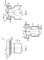
- an engine piston 100 is shown from a side perspective in FIG. 1 , and from two different perspectives in the fragmented views shown in FIGS. 2 and 3 .
- the piston 100 includes a crown portion 102 and a skirt portion 104.
- the skirt portion 104 forms a pin bore 106 that accommodates a pin (not shown) used to pivotally connect the piston to a connecting rod (not shown), which is connected to an engine crankshaft (not shown) in the known fashion.
- the crown portion 102 forms various grooves 108 in an outer cylindrical surface 109, which accommodate ring seals (not shown) that slidably and generally sealably engage the walls of the engine cylinder in which the piston 100 is reciprocally disposed.
- the crown 102 forms a bowl 110 having a concave shape along the topmost surface of the piston.
- the bowl is surrounded by an annularly shaped, flat crown surface 112 adjacent an outer periphery of the piston 100.
- the bowl 110 further forms an optional central depression 111.
- the piston 100 forms various features that operate to redirect and/or contain various moving masses within the cylinder during operation.
- these features operate to split the hot injector fuel plume that is provided to the cylinder when the piston is close to a top dead center position in the cylinder, and also which may be provided while the piston is approaching the top dead center position (e.g., pilot injection events) and/or is moving away from the top dead center position (e.g. post injection events during a combustion stroke).
- the fuel plume, a fuel atomization cloud, and/or a flame of burning fuel during these times of engine operation can be redirected in terms of flow direction and material dissipation in a fashion that reduces exposure of the various surrounding in-cylinder combustion surfaces to flame temperatures. By insulating cylinder surfaces from flame temperatures, retained heat and heat transfer to the metal of the surrounding engine components can be reduced, which in turn can provide a higher power output and/or higher power density to the engine, and also improve component reliability and service life.
- piston features that have been found to effectively redirect the various described engine cylinder combustion products, which features relate to an airfoil surface formed on the top crown surface, structures placed within the bowl of the piston, and also features relating to the shape of the piston bowl and/or a combination or combinations of these features.
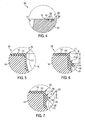
- FIG. 4 shows an enlarged detail view of an airfoil surface 200, the placement of which along the outer periphery of the crown surface 112 is shown in FIG. 2 .
- the airfoil surface 200 has a generally concave shape that extends annularly around at least a portion of the outer periphery of the topmost portion of the piston 100.
- the airfoil surface 200 has a negative camber that increases in a radial direction away from a crown centerline, as shown in FIG. 4 .
- a central chord 202 of the airfoil surface 200 coincides with the top surface 112 such that the airfoil surface 200 includes an expanding surface 204 that extends radially outwardly with respect to the piston 100 and sinks away from a plane that contains the flat surface 112.
- a converging surface 206 is disposed radially outwardly with respect to the expanding surface 204 and rises towards the plane that contains the flat surface 112.
- An inflection surface 208 is disposed between the expanding and converging surfaces 204 and 206 to form a bottom trough of the airfoil surface 200.
- a radius of curvature of the expanding surface 204 is larger than a radius of curvature of the converging surface 206 to create an airfoil effect that redirects moving fluids entering the airfoil surface 200 upwards and away from the piston and the cylinder walls with respect to the piston and cylinder.
- an expanding mass which may contain one or more of fuel injected into the cylinder, a mass of atomized or vaporizing fuel, burning fuel and air, and other combustion products, at least for an instant, moves in a downward and outward direction with respect to a central region of the cylinder towards the piston crown and also towards the cylinder walls.
- the expanding mass may contact the piston crown and follow the crown surface 112 in a radially outward direction.
- the outwardly moving mass will first encounter the expanding surface 204 and expand into a concave trough created within the airfoil surface 200 towards the inflection surface 208 at least for a short period.
- the expanding mass will contact the converging surface 206 and be redirected thereby upward and away from the piston 100.
- the expanding mass When exiting the concave trough created within the airfoil surface 200, the expanding mass will tend to move into and occupy a peripheral outward portion of the cylinder that lies radially inward with respect to the cylinder wall, thus reducing contact between the burning products and the cylinder wall, as is qualitatively denoted by the dashed-line arrows shown in the figure.
- FIGS. 5-7 Another feature of the piston 100 is shown in three alternative embodiments in FIGS. 5-7 .
- a sleeve 210 is connected to the piston crown 102 along a rim 212 of the bowl 110.
- the sleeve 210 which may be omitted in favor of the structures formed thereby being integrally formed in the parent material of the piston 100, has a generally L-shaped cross section extending along the top crown surface 112 and also forming a radially outward wall of the bowl 110 that extends down into the bowl 110.
- the radially outward wall of the bowl 110 forms a generally cylindrical surface 214 that extends in a downward direction from the rim 212 into the bowl 110.
- the rim 212 forms a sharp edge transition with the topmost crown surface 112 such that the moving mass, as previously described, which may enter a central portion of the bowl 110 and move radially outwardly with respect to the bowl, at least for an instant, can be directed upward relative to the piston and away from the cylinder walls, as is qualitatively denoted by the dashed-line arrows shown in the figure.
- the sleeve 210 includes an annular protrusion 216, which extends peripherally around the bowl 110 at a depth, d1, with respect to the flat crown surface 112 along a piston centerline.
- the depth, d1 may be about 12 mm. from the crown surface 112.
- FIG. 7 an alternative embodiment for the annular protrusion 218 is shown, which in this embodiment is disposed at a depth, d2, that is less than the depth d1 as shown in the embodiment of FIG. 6 .
- the protrusions 216 or 218 may alternatively be formed as integral structures of the parent piston material.
- Each of the protrusions 216 and 218 has a generally convexly shaped cross section that includes two radially inwardly extending surfaces 220 disposed on either side of an apex 222.
- These structures cause a radially outwardly moving mass, as described above, that is travelling from about the center of the bowl 110 to recirculate back towards the center of the bowl 110 as it is redirected when contacting the lower inwardly extending surface 220.
- the mass may at least temporarily create a toroidal-shaped flow disturbance or vortex, which has been found to trap therein or, stated differently, constrict dispersion of combustion products during combustion, at least temporarily.
- the constriction of the dispersion of combustion products has appreciable benefits for engine operation. Some of the benefits include a more complete combustion, because the fuel is concentrated around a central cylinder portion, avoidance of contact of the combustion products with the walls of the cylinder and the cylinder head, lower emissions, and other benefits that increase the power output of the engine and decrease heat rejection.
- the upper inwardly extending surface 220 may further cooperate with the lower inwardly extending surface 220 to create a second vortex on the upper side of the corresponding protrusion 216 and 218, as is generally denoted by dashed line arrows in FIGS. 6 and 7 , to provide a second barrier against the diffusion and migration of combustion products towards the outer radial portions of the cylinder during combustion.
- Placement of the annular protrusion 216 or 218 either higher or lower into the bowl generally depends on the amount of fuel injected into the cylinder, as well as on injection timing. In other words, such placement can be selected by the engine designer to suit the particular requirements of a particular engine application.
- the airfoil surface 200 and annular protrusion 216 or 218 can be selectively used together or separately in various piston embodiments depending on their effect and contribution to improved engine operation.
- Various piston embodiments are discussed below that incorporate some of these features.
- features, structures and/or elements of the pistons described that are the same or similar to corresponding features, structures and/or elements described above may be denoted by the same reference as previously used for simplicity, but such common denotation should not be construed as limiting to the scope of the present disclosure.
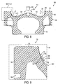
- a first alternative embodiment of the piston 100 is shown in the fragmented view of FIG. 8 , and a portion thereof is shown in the enlarged detail view of FIG. 9 .
- the piston 100 in this embodiment includes an annular protrusion 300 that, as best shown in FIG. 8 , has an upper converging surface 302 and a lower converging surface 304 that meet along a convex apex 306.
- a reference curve, denoted as "REF.” in the figure, is overlaid to highlight the difference in structure between the piston 100 and a baseline piston.
- the upper converging surface 302 has a larger radius, R1, than a radius, R2, of the lower converging surface 304.
- R1 is about 13.5 mm.
- R2 is about 6.9 mm.
- the illustrated piston embodiment is suitable for a particular engine compression ratio, and certain dimensions change depending on the desired compression ratio for a particular engine configuration.
- a bottom radius, R, of the piston bowl 110 is about 28mm., but can alternatively be shallower, for example, at 35mm., for engines having a higher compression ratio.
- the smaller radius R2 of the lower converging surface 304 causes a moving mass of combustion material, as previously described, that is travelling along the bowl 110, to be redirected back towards a central portion of the bowl 110.
- the relatively high velocity of the moving mass may create a low pressure region along the upper converging surface 302, at least for an instant, which will pull in surrounding material from the within the cylinder volume and also direct the same towards the central portion of the cylinder.
- FIG. 8 A qualitative illustration of the flow effects within the cylinder created by the protrusion 300 is denoted by arrows in FIG. 8 .
- the piston 100 is moving deeper into the cylinder, for example, during a combustion stroke and while fuel is being injected into the cylinder, such as during a continued-burn injection event.
- a fuel injector 308 is shown injecting one or more fuel streams 310 into the cylinder.
- the fuel streams 310 which may begin atomizing, mixing with surrounding air, and/or burning, may follow paths 312 along the faces of the bowl 110 until they reach the protrusion 300.
- the paths 312 may curl inward as they are redirected by the lower converging surface 304 of the protrusion 300, at least for an instant.
- surrounding material which can include air
- the surrounding air following the moving mass along path 312 and along the swirl paths 314 may, in some conditions, further insulate and contain the burning, moving mass from dispersion in the radially outward portions of the cylinder volume by creating a moving curtain of air around the moving, burning mass.
- the added air around the burning mass can further serve to provide oxygen for a more complete burn of the fuel present in the moving mass, thus increasing engine efficiency.
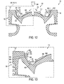
- a second alternative embodiment of the piston 100 is shown in the fragmented view of FIG. 10 , and a portion thereof is shown in the detail view of FIG. 11 .
- the piston 100 in this embodiment includes the annular protrusion 300, which is discussed above relative to the embodiment shown in FIGS. 8 and 9 , and further includes an airfoil surface 400.
- the airfoil surface 400 which is formed by an inner diverging surface 402 and an outer converging surface 404 that meet along a concave trough 406.
- a reference curve, denoted as "REF.” in the figure, is overlaid to highlight the different in structure between the piston 100 and a baseline piston design.
- REF reference curve
- the inner diverging surface 402 has a larger radius, R3, than a radius, R4, of the outer converging surface 404.
- R3 is about 47.3 mm.
- R4 is about 2.6 mm.
- the overall width of the airfoil surface 400 in a radial direction is about 13.9 mm.
- the smaller radius R4 of the outer converging surface 404 causes a moving mass of combustion material, as previously described, that may be travelling along the flat, crown surface 112 to be redirected upwards and away from the piston 100 and the walls of the cylinder in which the piston 100 reciprocates.
- the relatively high velocity of the moving mass that is redirected is, in part, attributable to the relatively shallow inner diverging surface 402, which causes fluid to travel towards and along the outer converging surface 404.
- FIG. 10 A qualitative illustration of the flow effects within the cylinder created by the airfoil surface 400, together with the protrusion 300, is denoted by arrows in FIG. 10 .
- the fuel injector 308 is shown injecting one or more fuel streams 310 into the cylinder.
- the fuel streams 310 which may begin atomizing, mixing with surrounding air, and/or burning, may follow paths 312 along the faces of the bowl 110 until they reach the protrusion 300.
- the paths 312 may curl inward as they are redirected, at least for an instant, by the lower converging surface 304 of the protrusion 300.
- surrounding material which can include air, may be pulled along the upper converging surface 302 along swirl paths 314 to follow the mass moving along the paths 312.
- the surrounding air following the moving mass along path 312 and along the swirl paths 314 may, in some conditions, further insulate and contain the burning, moving mass from dispersion in the radially outward portions of the cylinder volume by creating a moving curtain of air around the moving, burning mass.
- a further circulation of material may follow the path 316, which curls upwards and away from the piston 100 when flowing into and through the airfoil surface 400.
- a wall 410 surrounding the airfoil surface 400 and disposed along an outer, upper periphery of the piston 100 forms a ramp that causes any combustion products present in that area to move away from the region 408.
- the added air moving upward around the burning mass can further serve to provide oxygen for a more complete burn of the fuel present in the moving mass, thus increasing engine efficiency, and insulate the cylinder walls and region 408 from combustion products.
- a third alternative embodiment of the piston 100 is shown in the fragmented view of FIG. 12 , and a portion thereof is shown in the detail view of FIG. 13 .
- the piston 100 in this embodiment includes a more pronounced annular protrusion 500 than the protrusion 300 shown in the previously described embodiments, as well as a recirculation surface 600 formed within the bowl 110.
- the annular protrusion 500 includes a lower, partially diverging surface 502, and an upper diverging surface 504 that meet along a convex apex 506.
- the pronounced protrusion 500 includes two diverging surfaces surrounding the apex 506, which cooperate with the recirculation surface 600.
- the recirculation surface 600 has a generally circular cross section that forms a toroidal cavity 602 that is placed low within the bowl 110.
- the recirculation surface may have an elliptical cross section.
- a portion of the recirculation surface 600 meets the lower, partially diverging surface 502 of the protrusion 500 at an inflection edge 604, which extends peripherally around an edge of the toroidal cavity 602 between the recirculation surface 600 and the lower, partially diverging surface 502 of the protrusion 500.
- the recirculation surface 600 When compared to a baseline piston bowl, the outline of which is denoted by a line (REF.), the recirculation surface 600 is deeper into the piston and formed at a radius, R5, that is less than a baseline radius, R6, of a piston in that area. As shown, R5 is about 23.3 mm.. In the cross section shown in FIG. 13 , a centerpoint of the radius of the recirculation surface is below the inflection edge 604 in an axial direction with respect to the centerline of the piston and in a direction away from the flat crown surface 112.
- FIG. 12 A qualitative illustration of the flow effects within the cylinder created by the pronounced protrusion 500 and the recirculation surface 600 is denoted by arrows in FIG. 12 .
- the fuel injector 308 is shown injecting one or more fuel streams 310 into the cylinder.
- the fuel streams 310 which may begin atomizing, mixing with surrounding air, and/or burning, may follow paths 312 along inner, shallow faces 606 of the bowl 110 until they reach the recirculation surface 600.
- the combustion materials When reaching the recirculation surface 600, the combustion materials will sink into the toroidal cavity 602 and assume a swirling pattern 608 at least temporarily within the cavity 602 and generally below the inflection edge 604.
- a secondary swirl 610 induced by the lower, partially diverging surface 502 may enhance the swirling motion 608 of material within the toroidal cavity 602.
- surrounding material which can include air, may be pulled along the upper surface 504 along swirl paths 314 to follow the mass moving along the paths 608 and 610.
- the surrounding air, or a mixture containing air, the same or a different fuel and/or exhaust gas, following the moving along the swirl paths 314 may, in some conditions, further insulate and contain the burning, moving mass from dispersion in the radially outward portions of the cylinder volume by creating a moving curtain of air around the moving, burning mass.
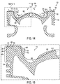
- a fourth alternative embodiment of the piston 100 is shown in the fragmented view of FIG. 14 , and a portion thereof is shown in the detail view of FIG. 15 .
- the piston 100 in this embodiment includes the pronounced annular protrusion 500, the recirculation surface 600 formed within the bowl 110, and further includes an airfoil surface 400.
- the airfoil surface 400 is similar to the airfoil surface 400 ( FIG. 10 ), which is formed by an inner diverging surface 402 and an outer converging surface 404 that meet along a concave trough 406.
- a reference curve, denoted as REF. in the figure, is overlaid to highlight the different in structure between the piston 100 and a baseline piston design.
- the airfoil surface 400 causes a moving mass of combustion material, as previously described, that may be travelling along the flat, crown surface 112 to be redirected upwards and away from the piston 100 and the walls of the cylinder in which the piston 100 reciprocates.
- Such motion is in addition to the swirling pattern 608 within the cavity 602, the secondary swirl 610 induced by the lower, partially diverging surface 502, and the surrounding material that is pulled along the upper surface 504 along swirl paths 314 to follow the mass moving along the paths 608 and 610.
- a wall 410 surrounding the airfoil surface 700 and disposed along an outer, upper periphery of the piston 100 forms a ramp that causes moving fluids away from the region 408.
- the added air moving upward around the burning mass can further serve to provide oxygen for a more complete burn of the fuel present in the moving mass, thus increasing engine efficiency, and insulate the cylinder walls and region 408 from combustion products.
- the present disclosure is applicable to pistons for internal combustion engines, which can be used in any application such as land or marine based applications, as well as for mobile or stationary applications.
- the various embodiments for piston features described herein have been found to have advantages in improving engine operation by increasing power output, decreasing fuel consumption and also decreasing emissions.
- Various graphs showing the changes in cylinder component operating temperatures and emissions, as indicated by NOx and soot emissions, in engine operation for various embodiments are shown in FIG. 16 .
- the various embodiments considered include different combination of the features described above, including the airfoil surface, annular protrusions, and recirculation cavities, which were used alone or in combinations, as well as changes in the geometrical features for each, including changing the radii of curvature for the various surfaces involved, for example, the radii R1 - R5, the relative position between features, and other characteristics.
- the presence and structure of these various features can have an appreciable effect on component temperature, NOx and soot emissions as compared to a baseline piston.
- FIG. 16 illustrates four different engine operating parameters for 19 different piston configurations, each piston configuration including various features set at various dimensions.
- the purpose of the investigation was to determine the effect of the various features on the engine operating parameters monitored, and to optimize a piston design for a particular engine application operating under specific parameters in terms of power, fuel timing, ignition timing, and others.
- each of the 19 alternative piston configurations is arranged along the horizontal axes 700.
- the total heat rejection, in J/cycle which is indicative of temperature for the flame deck of the cylinder head, the cylinder wall or liner, and the top of the piston, is plotted in the top chart along the topmost vertical axis 702.
- NOx concentration, in g/kW-hr. is plotted in the middle graph along the middle vertical axis 704. Soot, also in g/kw-hr., in plotted in the lower chart along the lower vertical axis 706.
- the leftmost piston design which is denoted by box 708, for the test conditions applied, showed a total heat rejection of about 2791 J/cycle, a NOx output of about 15.4 g/kw-hr., and a soot output of about 0.607 g/kw-hr.
- the heat rejection ranged between about 2630 J/cycle, at configuration 710, and 2000 J/cycle, at configuration 712, but with differing NOx and soot emissions, as shown in the graph.
- the piston configuration 714 included an airfoil surface and a recirculation cavity, similar to the embodiment shown in FIGS. 14 and 15 .
Landscapes
- Engineering & Computer Science (AREA)
- Chemical & Material Sciences (AREA)
- Combustion & Propulsion (AREA)
- Mechanical Engineering (AREA)
- General Engineering & Computer Science (AREA)
- Combustion Methods Of Internal-Combustion Engines (AREA)
- Pistons, Piston Rings, And Cylinders (AREA)
Claims (4)
- Kolben (100) für eine Brennkraftmaschine, umfassend:einen Kolben(100)-Körper, der einen Kronenabschnitt (102) und einen Schürzenabschnitt (104) bildet, wobei der Schürzenabschnitt (104) eine Bohrung einschließt, die angeordnet ist, um einen Stift zum Verbinden des Kolbens (100) mit einer Pleuelstange aufzunehmen, wobei der Kronenabschnitt (102) eine Schale (110) bildet, die von einer flachen Kronenfläche (112) umgeben ist, die eine Ringform aufweist und entlang einer Ebene angeordnet ist, wobei sich die Schale (110) und die flache Kronenfläche (112) entlang einer kreisförmigen Kante treffen, die einen Rand (212) der Schale (110) umgibt; undeine Schaufelblattoberfläche (200), die in der flachen Kronenoberfläche (112) ausgebildet ist,wobei die Schaufelblattoberfläche (200) eine konkave Form aufweist und sich ringförmig um den Rand (212) der Schale (110) erstreckt,wobei die Schaufelblattoberfläche (200) eine sich erweiternde Oberfläche (204) einschließt, die sich in Bezug auf den Kolben (100) radial nach außen erstreckt und von einer Ebene, die die flache Oberfläche (112) enthält, absinkt,wobei die Schaufelblattoberfläche (200) ferner eine konvergierende Oberfläche (206) einschließt, die in Bezug auf die sich erweiternde Oberfläche (204) radial nach außen angeordnet ist und in Richtung der Ebene, die die flache Oberfläche (112) enthält, ansteigt,wobei die Schaufelblattoberfläche (200) ferner eine Biegeoberfläche (208) einschließt, die zwischen der sich erweiternden und der konvergierenden Oberfläche (204) angeordnet ist, um eine untere Mulde der Schaufelblattoberfläche (200) zu bilden,wobei ein Krümmungsradius der sich erweiternden Oberfläche (204) größer ist als ein Krümmungsradius der konvergierenden Oberfläche (206) und die Schaufelblattoberfläche (200) einen Schaufelblatteffekt erzeugt, der bewegte Fluide, die in die Schaufelblattoberfläche (200) eintreten, nach oben und weg von dem Kolben (100) leitet, wobei der Krümmungsradius der sich erweiternden Oberfläche (204) eine Nennabmessung von 47,3 mm aufweist und der Krümmungsradius der konvergierenden Oberfläche (206) eine Nennabmessung von 2,6 mm aufweist, wobei eine Gesamtbreite der Schaufelblattoberfläche (200) in der radialen Richtung eine Nennabmessung von 13,9 mm aufweist.
- Kolben (100) nach Anspruch 1, ferner umfassend eine zylindrische Wand (410), die die Schaufelblattoberfläche (200) umgibt und entlang eines äußeren, oberen Umfangs der Kolbenkrone (102) angeordnet ist.
- Kolben (100) nach einem der vorstehenden Ansprüche, ferner umfassend einen ringförmigen Vorsprung (216), der innerhalb der Schale (110) angrenzend an den Rand (212) angeordnet ist.
- Kolben (100) nach Anspruch 3, wobei der ringförmige Vorsprung (216) eine obere, sich nach innen erstreckende Oberfläche (220) und eine untere, sich nach innen erstreckende Oberfläche (220) bildet, die sich entlang eines Scheitels (222) treffen, der innerhalb der Schale (110) angeordnet ist, und wobei jede der oberen, sich nach innen erstreckenden Oberfläche (220) und der unteren, sich nach innen erstreckenden Oberfläche (220) eine konvergierende Oberfläche (206) oder eine sich erweiternde Oberfläche (204) ist.
Applications Claiming Priority (1)
| Application Number | Priority Date | Filing Date | Title |
|---|---|---|---|
| US14/546,639 US20160138518A1 (en) | 2014-11-18 | 2014-11-18 | Engine Piston |
Publications (3)
| Publication Number | Publication Date |
|---|---|
| EP3023611A2 EP3023611A2 (de) | 2016-05-25 |
| EP3023611A3 EP3023611A3 (de) | 2016-06-15 |
| EP3023611B1 true EP3023611B1 (de) | 2021-04-14 |
Family
ID=54478548
Family Applications (1)
| Application Number | Title | Priority Date | Filing Date |
|---|---|---|---|
| EP15003188.8A Active EP3023611B1 (de) | 2014-11-18 | 2015-11-06 | Motorkolben |
Country Status (3)
| Country | Link |
|---|---|
| US (1) | US20160138518A1 (de) |
| EP (1) | EP3023611B1 (de) |
| CN (1) | CN105604727B (de) |
Families Citing this family (1)
| Publication number | Priority date | Publication date | Assignee | Title |
|---|---|---|---|---|
| DE102019006760A1 (de) * | 2019-09-27 | 2021-04-01 | Daimler Ag | Kolben für eine Hubkolbenmaschine, insbesondere eines Kraftfahrzeugs, sowie Hubkolbenmaschine für ein Kraftfahrzeug |
Family Cites Families (8)
| Publication number | Priority date | Publication date | Assignee | Title |
|---|---|---|---|---|
| DE4415073A1 (de) * | 1994-04-29 | 1995-11-02 | Fev Motorentech Gmbh & Co Kg | Hubkolbenmotor mit direkter Kraftstoffeinspritzeinrichtung und Funkenzündung, insbesondere für den Betrieb mit Alkoholkraftstoff |
| DE19829384A1 (de) * | 1998-07-01 | 2000-01-05 | Man Nutzfahrzeuge Ag | Kolben für eine Diesel-Brennkraftmaschine |
| US8276563B2 (en) * | 2002-06-28 | 2012-10-02 | Cummins, Inc. | Internal combustion engine piston |
| FR2885958A1 (fr) * | 2005-05-20 | 2006-11-24 | Renault Sas | Piston pour moteur a combustion interne et moteur a combustion interne comportant au moins un tel piston |
| FR2927121B1 (fr) * | 2008-02-06 | 2010-02-12 | Renault Sas | Moteur a combustion interne comportant un bol de combustion a double cavite pour un injecteur ultrasonore |
| DE102009025063A1 (de) * | 2009-06-10 | 2010-12-30 | Ks Kolbenschmidt Gmbh | Leichtmetallkolben mit Mehrfach-Omega-Brennraummulde |
| US8677974B2 (en) * | 2010-05-04 | 2014-03-25 | Southwest Research Institute | Piston bowl with flat bottom |
| DE102012103195A1 (de) * | 2012-04-13 | 2013-10-17 | Mwm Gmbh | Kolben einer Brennkraftmaschine |
-
2014
- 2014-11-18 US US14/546,639 patent/US20160138518A1/en not_active Abandoned
-
2015
- 2015-11-06 EP EP15003188.8A patent/EP3023611B1/de active Active
- 2015-11-17 CN CN201510794380.5A patent/CN105604727B/zh not_active Expired - Fee Related
Non-Patent Citations (1)
| Title |
|---|
| None * |
Also Published As
| Publication number | Publication date |
|---|---|
| CN105604727B (zh) | 2020-04-03 |
| CN105604727A (zh) | 2016-05-25 |
| EP3023611A3 (de) | 2016-06-15 |
| US20160138518A1 (en) | 2016-05-19 |
| EP3023611A2 (de) | 2016-05-25 |
Similar Documents
| Publication | Publication Date | Title |
|---|---|---|
| EP3023610B1 (de) | Motorkolben | |
| US10184388B1 (en) | Engine piston | |
| US20160169153A1 (en) | Engine Piston | |
| USRE46806E1 (en) | Piston for internal combustion engine | |
| US5737999A (en) | Blowby pressure control above an oil control ring in a reciprocating internal combustion engine | |
| US20160138517A1 (en) | Engine Piston | |
| KR20190106574A (ko) | 디젤 엔진용 피스톤 및 이를 포함하는 직분사식 디젤 엔진 | |
| EP3023611B1 (de) | Motorkolben | |
| EP3023612B1 (de) | Motorkolben | |
| US20160169152A1 (en) | Engine Piston | |
| US5743171A (en) | Oil control ring and groove arrangement for improved blowby control | |
| CN113756982B (zh) | 内燃机和具有带有非轴对称轮廓的台阶式燃烧凹腔的活塞 | |
| US9822729B2 (en) | Engine piston having a notched top land | |
| RU104246U1 (ru) | Поршень для двигателя внутреннего сгорания (варианты) | |
| US11959436B2 (en) | Piston including spiral features to increase in-cylinder swirl | |
| US12163484B2 (en) | Piston, block assembly, and method for cooling | |
| EP3839225B1 (de) | Kolben für brennkraftmaschine mit ventiltaschenschritt zum verlangsamen des verbrennungsgasflusses | |
| JP6489157B2 (ja) | エンジンの燃焼室構造 | |
| FI128417B (en) | Cylinder liner with slots | |
| CN118715361A (zh) | 用于改善燃烧稳定性的低压缩天然气发动机活塞顶凹腔 | |
| JP2000282865A (ja) | 内燃機関の燃焼室段差による渦流発生機構 | |
| JP2018040253A (ja) | 内燃機関 | |
| JP2016217204A (ja) | 内燃機関 |
Legal Events
| Date | Code | Title | Description |
|---|---|---|---|
| PUAL | Search report despatched |
Free format text: ORIGINAL CODE: 0009013 |
|
| AK | Designated contracting states |
Kind code of ref document: A2 Designated state(s): AL AT BE BG CH CY CZ DE DK EE ES FI FR GB GR HR HU IE IS IT LI LT LU LV MC MK MT NL NO PL PT RO RS SE SI SK SM TR |
|
| AX | Request for extension of the european patent |
Extension state: BA ME |
|
| PUAI | Public reference made under article 153(3) epc to a published international application that has entered the european phase |
Free format text: ORIGINAL CODE: 0009012 |
|
| AK | Designated contracting states |
Kind code of ref document: A3 Designated state(s): AL AT BE BG CH CY CZ DE DK EE ES FI FR GB GR HR HU IE IS IT LI LT LU LV MC MK MT NL NO PL PT RO RS SE SI SK SM TR |
|
| AX | Request for extension of the european patent |
Extension state: BA ME |
|
| RIC1 | Information provided on ipc code assigned before grant |
Ipc: F02B 23/06 20060101AFI20160510BHEP Ipc: F02B 23/10 20060101ALI20160510BHEP |
|
| STAA | Information on the status of an ep patent application or granted ep patent |
Free format text: STATUS: REQUEST FOR EXAMINATION WAS MADE |
|
| 17P | Request for examination filed |
Effective date: 20161207 |
|
| RBV | Designated contracting states (corrected) |
Designated state(s): AL AT BE BG CH CY CZ DE DK EE ES FI FR GB GR HR HU IE IS IT LI LT LU LV MC MK MT NL NO PL PT RO RS SE SI SK SM TR |
|
| STAA | Information on the status of an ep patent application or granted ep patent |
Free format text: STATUS: EXAMINATION IS IN PROGRESS |
|
| 17Q | First examination report despatched |
Effective date: 20170522 |
|
| GRAP | Despatch of communication of intention to grant a patent |
Free format text: ORIGINAL CODE: EPIDOSNIGR1 |
|
| STAA | Information on the status of an ep patent application or granted ep patent |
Free format text: STATUS: GRANT OF PATENT IS INTENDED |
|
| INTG | Intention to grant announced |
Effective date: 20201109 |
|
| GRAS | Grant fee paid |
Free format text: ORIGINAL CODE: EPIDOSNIGR3 |
|
| GRAA | (expected) grant |
Free format text: ORIGINAL CODE: 0009210 |
|
| STAA | Information on the status of an ep patent application or granted ep patent |
Free format text: STATUS: THE PATENT HAS BEEN GRANTED |
|
| AK | Designated contracting states |
Kind code of ref document: B1 Designated state(s): AL AT BE BG CH CY CZ DE DK EE ES FI FR GB GR HR HU IE IS IT LI LT LU LV MC MK MT NL NO PL PT RO RS SE SI SK SM TR |
|
| REG | Reference to a national code |
Ref country code: GB Ref legal event code: FG4D |
|
| REG | Reference to a national code |
Ref country code: CH Ref legal event code: EP |
|
| REG | Reference to a national code |
Ref country code: DE Ref legal event code: R096 Ref document number: 602015068002 Country of ref document: DE |
|
| REG | Reference to a national code |
Ref country code: IE Ref legal event code: FG4D |
|
| REG | Reference to a national code |
Ref country code: AT Ref legal event code: REF Ref document number: 1382575 Country of ref document: AT Kind code of ref document: T Effective date: 20210515 |
|
| REG | Reference to a national code |
Ref country code: LT Ref legal event code: MG9D |
|
| REG | Reference to a national code |
Ref country code: AT Ref legal event code: MK05 Ref document number: 1382575 Country of ref document: AT Kind code of ref document: T Effective date: 20210414 |
|
| REG | Reference to a national code |
Ref country code: NL Ref legal event code: MP Effective date: 20210414 |
|
| PG25 | Lapsed in a contracting state [announced via postgrant information from national office to epo] |
Ref country code: HR Free format text: LAPSE BECAUSE OF FAILURE TO SUBMIT A TRANSLATION OF THE DESCRIPTION OR TO PAY THE FEE WITHIN THE PRESCRIBED TIME-LIMIT Effective date: 20210414 Ref country code: FI Free format text: LAPSE BECAUSE OF FAILURE TO SUBMIT A TRANSLATION OF THE DESCRIPTION OR TO PAY THE FEE WITHIN THE PRESCRIBED TIME-LIMIT Effective date: 20210414 Ref country code: NL Free format text: LAPSE BECAUSE OF FAILURE TO SUBMIT A TRANSLATION OF THE DESCRIPTION OR TO PAY THE FEE WITHIN THE PRESCRIBED TIME-LIMIT Effective date: 20210414 Ref country code: LT Free format text: LAPSE BECAUSE OF FAILURE TO SUBMIT A TRANSLATION OF THE DESCRIPTION OR TO PAY THE FEE WITHIN THE PRESCRIBED TIME-LIMIT Effective date: 20210414 Ref country code: AT Free format text: LAPSE BECAUSE OF FAILURE TO SUBMIT A TRANSLATION OF THE DESCRIPTION OR TO PAY THE FEE WITHIN THE PRESCRIBED TIME-LIMIT Effective date: 20210414 Ref country code: BG Free format text: LAPSE BECAUSE OF FAILURE TO SUBMIT A TRANSLATION OF THE DESCRIPTION OR TO PAY THE FEE WITHIN THE PRESCRIBED TIME-LIMIT Effective date: 20210714 |
|
| PG25 | Lapsed in a contracting state [announced via postgrant information from national office to epo] |
Ref country code: GR Free format text: LAPSE BECAUSE OF FAILURE TO SUBMIT A TRANSLATION OF THE DESCRIPTION OR TO PAY THE FEE WITHIN THE PRESCRIBED TIME-LIMIT Effective date: 20210715 Ref country code: IS Free format text: LAPSE BECAUSE OF FAILURE TO SUBMIT A TRANSLATION OF THE DESCRIPTION OR TO PAY THE FEE WITHIN THE PRESCRIBED TIME-LIMIT Effective date: 20210814 Ref country code: LV Free format text: LAPSE BECAUSE OF FAILURE TO SUBMIT A TRANSLATION OF THE DESCRIPTION OR TO PAY THE FEE WITHIN THE PRESCRIBED TIME-LIMIT Effective date: 20210414 Ref country code: PL Free format text: LAPSE BECAUSE OF FAILURE TO SUBMIT A TRANSLATION OF THE DESCRIPTION OR TO PAY THE FEE WITHIN THE PRESCRIBED TIME-LIMIT Effective date: 20210414 Ref country code: PT Free format text: LAPSE BECAUSE OF FAILURE TO SUBMIT A TRANSLATION OF THE DESCRIPTION OR TO PAY THE FEE WITHIN THE PRESCRIBED TIME-LIMIT Effective date: 20210816 Ref country code: NO Free format text: LAPSE BECAUSE OF FAILURE TO SUBMIT A TRANSLATION OF THE DESCRIPTION OR TO PAY THE FEE WITHIN THE PRESCRIBED TIME-LIMIT Effective date: 20210714 Ref country code: ES Free format text: LAPSE BECAUSE OF FAILURE TO SUBMIT A TRANSLATION OF THE DESCRIPTION OR TO PAY THE FEE WITHIN THE PRESCRIBED TIME-LIMIT Effective date: 20210414 Ref country code: RS Free format text: LAPSE BECAUSE OF FAILURE TO SUBMIT A TRANSLATION OF THE DESCRIPTION OR TO PAY THE FEE WITHIN THE PRESCRIBED TIME-LIMIT Effective date: 20210414 Ref country code: SE Free format text: LAPSE BECAUSE OF FAILURE TO SUBMIT A TRANSLATION OF THE DESCRIPTION OR TO PAY THE FEE WITHIN THE PRESCRIBED TIME-LIMIT Effective date: 20210414 |
|
| REG | Reference to a national code |
Ref country code: DE Ref legal event code: R097 Ref document number: 602015068002 Country of ref document: DE |
|
| PG25 | Lapsed in a contracting state [announced via postgrant information from national office to epo] |
Ref country code: SM Free format text: LAPSE BECAUSE OF FAILURE TO SUBMIT A TRANSLATION OF THE DESCRIPTION OR TO PAY THE FEE WITHIN THE PRESCRIBED TIME-LIMIT Effective date: 20210414 Ref country code: SK Free format text: LAPSE BECAUSE OF FAILURE TO SUBMIT A TRANSLATION OF THE DESCRIPTION OR TO PAY THE FEE WITHIN THE PRESCRIBED TIME-LIMIT Effective date: 20210414 Ref country code: CZ Free format text: LAPSE BECAUSE OF FAILURE TO SUBMIT A TRANSLATION OF THE DESCRIPTION OR TO PAY THE FEE WITHIN THE PRESCRIBED TIME-LIMIT Effective date: 20210414 Ref country code: DK Free format text: LAPSE BECAUSE OF FAILURE TO SUBMIT A TRANSLATION OF THE DESCRIPTION OR TO PAY THE FEE WITHIN THE PRESCRIBED TIME-LIMIT Effective date: 20210414 Ref country code: EE Free format text: LAPSE BECAUSE OF FAILURE TO SUBMIT A TRANSLATION OF THE DESCRIPTION OR TO PAY THE FEE WITHIN THE PRESCRIBED TIME-LIMIT Effective date: 20210414 Ref country code: RO Free format text: LAPSE BECAUSE OF FAILURE TO SUBMIT A TRANSLATION OF THE DESCRIPTION OR TO PAY THE FEE WITHIN THE PRESCRIBED TIME-LIMIT Effective date: 20210414 |
|
| PLBE | No opposition filed within time limit |
Free format text: ORIGINAL CODE: 0009261 |
|
| STAA | Information on the status of an ep patent application or granted ep patent |
Free format text: STATUS: NO OPPOSITION FILED WITHIN TIME LIMIT |
|
| 26N | No opposition filed |
Effective date: 20220117 |
|
| PG25 | Lapsed in a contracting state [announced via postgrant information from national office to epo] |
Ref country code: IS Free format text: LAPSE BECAUSE OF FAILURE TO SUBMIT A TRANSLATION OF THE DESCRIPTION OR TO PAY THE FEE WITHIN THE PRESCRIBED TIME-LIMIT Effective date: 20210814 Ref country code: AL Free format text: LAPSE BECAUSE OF FAILURE TO SUBMIT A TRANSLATION OF THE DESCRIPTION OR TO PAY THE FEE WITHIN THE PRESCRIBED TIME-LIMIT Effective date: 20210414 |
|
| PG25 | Lapsed in a contracting state [announced via postgrant information from national office to epo] |
Ref country code: MC Free format text: LAPSE BECAUSE OF FAILURE TO SUBMIT A TRANSLATION OF THE DESCRIPTION OR TO PAY THE FEE WITHIN THE PRESCRIBED TIME-LIMIT Effective date: 20210414 |
|
| REG | Reference to a national code |
Ref country code: CH Ref legal event code: PL |
|
| PG25 | Lapsed in a contracting state [announced via postgrant information from national office to epo] |
Ref country code: LU Free format text: LAPSE BECAUSE OF NON-PAYMENT OF DUE FEES Effective date: 20211106 Ref country code: IT Free format text: LAPSE BECAUSE OF FAILURE TO SUBMIT A TRANSLATION OF THE DESCRIPTION OR TO PAY THE FEE WITHIN THE PRESCRIBED TIME-LIMIT Effective date: 20210414 Ref country code: BE Free format text: LAPSE BECAUSE OF NON-PAYMENT OF DUE FEES Effective date: 20211130 |
|
| REG | Reference to a national code |
Ref country code: BE Ref legal event code: MM Effective date: 20211130 |
|
| PG25 | Lapsed in a contracting state [announced via postgrant information from national office to epo] |
Ref country code: IE Free format text: LAPSE BECAUSE OF NON-PAYMENT OF DUE FEES Effective date: 20211106 |
|
| PG25 | Lapsed in a contracting state [announced via postgrant information from national office to epo] |
Ref country code: FR Free format text: LAPSE BECAUSE OF NON-PAYMENT OF DUE FEES Effective date: 20211130 |
|
| PG25 | Lapsed in a contracting state [announced via postgrant information from national office to epo] |
Ref country code: HU Free format text: LAPSE BECAUSE OF FAILURE TO SUBMIT A TRANSLATION OF THE DESCRIPTION OR TO PAY THE FEE WITHIN THE PRESCRIBED TIME-LIMIT; INVALID AB INITIO Effective date: 20151106 |
|
| P01 | Opt-out of the competence of the unified patent court (upc) registered |
Effective date: 20230517 |
|
| PG25 | Lapsed in a contracting state [announced via postgrant information from national office to epo] |
Ref country code: CY Free format text: LAPSE BECAUSE OF FAILURE TO SUBMIT A TRANSLATION OF THE DESCRIPTION OR TO PAY THE FEE WITHIN THE PRESCRIBED TIME-LIMIT Effective date: 20210414 |
|
| PG25 | Lapsed in a contracting state [announced via postgrant information from national office to epo] |
Ref country code: LI Free format text: LAPSE BECAUSE OF NON-PAYMENT OF DUE FEES Effective date: 20220630 Ref country code: CH Free format text: LAPSE BECAUSE OF NON-PAYMENT OF DUE FEES Effective date: 20220630 |
|
| PG25 | Lapsed in a contracting state [announced via postgrant information from national office to epo] |
Ref country code: MK Free format text: LAPSE BECAUSE OF FAILURE TO SUBMIT A TRANSLATION OF THE DESCRIPTION OR TO PAY THE FEE WITHIN THE PRESCRIBED TIME-LIMIT Effective date: 20210414 |
|
| PG25 | Lapsed in a contracting state [announced via postgrant information from national office to epo] |
Ref country code: MT Free format text: LAPSE BECAUSE OF FAILURE TO SUBMIT A TRANSLATION OF THE DESCRIPTION OR TO PAY THE FEE WITHIN THE PRESCRIBED TIME-LIMIT Effective date: 20210414 |
|
| PGFP | Annual fee paid to national office [announced via postgrant information from national office to epo] |
Ref country code: DE Payment date: 20251022 Year of fee payment: 11 |
|
| PGFP | Annual fee paid to national office [announced via postgrant information from national office to epo] |
Ref country code: GB Payment date: 20251022 Year of fee payment: 11 |
|
| PGFP | Annual fee paid to national office [announced via postgrant information from national office to epo] |
Ref country code: TR Payment date: 20251031 Year of fee payment: 11 |