EP3023616A1 - Variable welle für hydraulikeinheit - Google Patents
Variable welle für hydraulikeinheit Download PDFInfo
- Publication number
- EP3023616A1 EP3023616A1 EP15195969.9A EP15195969A EP3023616A1 EP 3023616 A1 EP3023616 A1 EP 3023616A1 EP 15195969 A EP15195969 A EP 15195969A EP 3023616 A1 EP3023616 A1 EP 3023616A1
- Authority
- EP
- European Patent Office
- Prior art keywords
- inches
- flange
- shaft
- splines
- variable shaft
- Prior art date
- Legal status (The legal status is an assumption and is not a legal conclusion. Google has not performed a legal analysis and makes no representation as to the accuracy of the status listed.)
- Granted
Links
Images
Classifications
-
- F—MECHANICAL ENGINEERING; LIGHTING; HEATING; WEAPONS; BLASTING
- F16—ENGINEERING ELEMENTS AND UNITS; GENERAL MEASURES FOR PRODUCING AND MAINTAINING EFFECTIVE FUNCTIONING OF MACHINES OR INSTALLATIONS; THERMAL INSULATION IN GENERAL
- F16C—SHAFTS; FLEXIBLE SHAFTS; ELEMENTS OR CRANKSHAFT MECHANISMS; ROTARY BODIES OTHER THAN GEARING ELEMENTS; BEARINGS
- F16C3/00—Shafts; Axles; Cranks; Eccentrics
- F16C3/02—Shafts; Axles
-
- F—MECHANICAL ENGINEERING; LIGHTING; HEATING; WEAPONS; BLASTING
- F02—COMBUSTION ENGINES; HOT-GAS OR COMBUSTION-PRODUCT ENGINE PLANTS
- F02C—GAS-TURBINE PLANTS; AIR INTAKES FOR JET-PROPULSION PLANTS; CONTROLLING FUEL SUPPLY IN AIR-BREATHING JET-PROPULSION PLANTS
- F02C7/00—Features, components parts, details or accessories, not provided for in, or of interest apart form groups F02C1/00 - F02C6/00; Air intakes for jet-propulsion plants
- F02C7/32—Arrangement, mounting, or driving, of auxiliaries
-
- F—MECHANICAL ENGINEERING; LIGHTING; HEATING; WEAPONS; BLASTING
- F04—POSITIVE - DISPLACEMENT MACHINES FOR LIQUIDS; PUMPS FOR LIQUIDS OR ELASTIC FLUIDS
- F04B—POSITIVE-DISPLACEMENT MACHINES FOR LIQUIDS; PUMPS
- F04B1/00—Multi-cylinder machines or pumps characterised by number or arrangement of cylinders
- F04B1/12—Multi-cylinder machines or pumps characterised by number or arrangement of cylinders having cylinder axes coaxial with, or parallel or inclined to, main shaft axis
- F04B1/20—Multi-cylinder machines or pumps characterised by number or arrangement of cylinders having cylinder axes coaxial with, or parallel or inclined to, main shaft axis having rotary cylinder block
-
- F—MECHANICAL ENGINEERING; LIGHTING; HEATING; WEAPONS; BLASTING
- F04—POSITIVE - DISPLACEMENT MACHINES FOR LIQUIDS; PUMPS FOR LIQUIDS OR ELASTIC FLUIDS
- F04B—POSITIVE-DISPLACEMENT MACHINES FOR LIQUIDS; PUMPS
- F04B1/00—Multi-cylinder machines or pumps characterised by number or arrangement of cylinders
- F04B1/12—Multi-cylinder machines or pumps characterised by number or arrangement of cylinders having cylinder axes coaxial with, or parallel or inclined to, main shaft axis
- F04B1/20—Multi-cylinder machines or pumps characterised by number or arrangement of cylinders having cylinder axes coaxial with, or parallel or inclined to, main shaft axis having rotary cylinder block
- F04B1/2014—Details or component parts
-
- F—MECHANICAL ENGINEERING; LIGHTING; HEATING; WEAPONS; BLASTING
- F04—POSITIVE - DISPLACEMENT MACHINES FOR LIQUIDS; PUMPS FOR LIQUIDS OR ELASTIC FLUIDS
- F04B—POSITIVE-DISPLACEMENT MACHINES FOR LIQUIDS; PUMPS
- F04B1/00—Multi-cylinder machines or pumps characterised by number or arrangement of cylinders
- F04B1/12—Multi-cylinder machines or pumps characterised by number or arrangement of cylinders having cylinder axes coaxial with, or parallel or inclined to, main shaft axis
- F04B1/20—Multi-cylinder machines or pumps characterised by number or arrangement of cylinders having cylinder axes coaxial with, or parallel or inclined to, main shaft axis having rotary cylinder block
- F04B1/2014—Details or component parts
- F04B1/2064—Housings
-
- F—MECHANICAL ENGINEERING; LIGHTING; HEATING; WEAPONS; BLASTING
- F16—ENGINEERING ELEMENTS AND UNITS; GENERAL MEASURES FOR PRODUCING AND MAINTAINING EFFECTIVE FUNCTIONING OF MACHINES OR INSTALLATIONS; THERMAL INSULATION IN GENERAL
- F16C—SHAFTS; FLEXIBLE SHAFTS; ELEMENTS OR CRANKSHAFT MECHANISMS; ROTARY BODIES OTHER THAN GEARING ELEMENTS; BEARINGS
- F16C33/00—Parts of bearings; Special methods for making bearings or parts thereof
- F16C33/30—Parts of ball or roller bearings
- F16C33/58—Raceways; Race rings
- F16C33/581—Raceways; Race rings integral with other parts, e.g. with housings or machine elements such as shafts or gear wheels
-
- F—MECHANICAL ENGINEERING; LIGHTING; HEATING; WEAPONS; BLASTING
- F16—ENGINEERING ELEMENTS AND UNITS; GENERAL MEASURES FOR PRODUCING AND MAINTAINING EFFECTIVE FUNCTIONING OF MACHINES OR INSTALLATIONS; THERMAL INSULATION IN GENERAL
- F16C—SHAFTS; FLEXIBLE SHAFTS; ELEMENTS OR CRANKSHAFT MECHANISMS; ROTARY BODIES OTHER THAN GEARING ELEMENTS; BEARINGS
- F16C33/00—Parts of bearings; Special methods for making bearings or parts thereof
- F16C33/30—Parts of ball or roller bearings
- F16C33/58—Raceways; Race rings
- F16C33/583—Details of specific parts of races
- F16C33/585—Details of specific parts of races of raceways, e.g. ribs to guide the rollers
-
- F—MECHANICAL ENGINEERING; LIGHTING; HEATING; WEAPONS; BLASTING
- F16—ENGINEERING ELEMENTS AND UNITS; GENERAL MEASURES FOR PRODUCING AND MAINTAINING EFFECTIVE FUNCTIONING OF MACHINES OR INSTALLATIONS; THERMAL INSULATION IN GENERAL
- F16H—GEARING
- F16H39/00—Rotary fluid gearing using pumps and motors of the volumetric type, i.e. passing a predetermined volume of fluid per revolution
- F16H39/04—Rotary fluid gearing using pumps and motors of the volumetric type, i.e. passing a predetermined volume of fluid per revolution with liquid motor and pump combined in one unit
- F16H39/06—Rotary fluid gearing using pumps and motors of the volumetric type, i.e. passing a predetermined volume of fluid per revolution with liquid motor and pump combined in one unit pump and motor being of the same type
- F16H39/08—Rotary fluid gearing using pumps and motors of the volumetric type, i.e. passing a predetermined volume of fluid per revolution with liquid motor and pump combined in one unit pump and motor being of the same type each with one main shaft and provided with pistons reciprocating in cylinders
- F16H39/10—Rotary fluid gearing using pumps and motors of the volumetric type, i.e. passing a predetermined volume of fluid per revolution with liquid motor and pump combined in one unit pump and motor being of the same type each with one main shaft and provided with pistons reciprocating in cylinders with cylinders arranged around, and parallel or approximately parallel to the main axis of the gearing
- F16H39/14—Rotary fluid gearing using pumps and motors of the volumetric type, i.e. passing a predetermined volume of fluid per revolution with liquid motor and pump combined in one unit pump and motor being of the same type each with one main shaft and provided with pistons reciprocating in cylinders with cylinders arranged around, and parallel or approximately parallel to the main axis of the gearing with cylinders carried in rotary cylinder blocks or cylinder-bearing members
-
- F—MECHANICAL ENGINEERING; LIGHTING; HEATING; WEAPONS; BLASTING
- F05—INDEXING SCHEMES RELATING TO ENGINES OR PUMPS IN VARIOUS SUBCLASSES OF CLASSES F01-F04
- F05D—INDEXING SCHEME FOR ASPECTS RELATING TO NON-POSITIVE-DISPLACEMENT MACHINES OR ENGINES, GAS-TURBINES OR JET-PROPULSION PLANTS
- F05D2220/00—Application
- F05D2220/70—Application in combination with
- F05D2220/76—Application in combination with an electrical generator
-
- F—MECHANICAL ENGINEERING; LIGHTING; HEATING; WEAPONS; BLASTING
- F05—INDEXING SCHEMES RELATING TO ENGINES OR PUMPS IN VARIOUS SUBCLASSES OF CLASSES F01-F04
- F05D—INDEXING SCHEME FOR ASPECTS RELATING TO NON-POSITIVE-DISPLACEMENT MACHINES OR ENGINES, GAS-TURBINES OR JET-PROPULSION PLANTS
- F05D2230/00—Manufacture
- F05D2230/50—Building or constructing in particular ways
- F05D2230/53—Building or constructing in particular ways by integrally manufacturing a component, e.g. by milling from a billet or one piece construction
-
- F—MECHANICAL ENGINEERING; LIGHTING; HEATING; WEAPONS; BLASTING
- F05—INDEXING SCHEMES RELATING TO ENGINES OR PUMPS IN VARIOUS SUBCLASSES OF CLASSES F01-F04
- F05D—INDEXING SCHEME FOR ASPECTS RELATING TO NON-POSITIVE-DISPLACEMENT MACHINES OR ENGINES, GAS-TURBINES OR JET-PROPULSION PLANTS
- F05D2260/00—Function
- F05D2260/40—Transmission of power
- F05D2260/406—Transmission of power through hydraulic systems
-
- F—MECHANICAL ENGINEERING; LIGHTING; HEATING; WEAPONS; BLASTING
- F16—ENGINEERING ELEMENTS AND UNITS; GENERAL MEASURES FOR PRODUCING AND MAINTAINING EFFECTIVE FUNCTIONING OF MACHINES OR INSTALLATIONS; THERMAL INSULATION IN GENERAL
- F16C—SHAFTS; FLEXIBLE SHAFTS; ELEMENTS OR CRANKSHAFT MECHANISMS; ROTARY BODIES OTHER THAN GEARING ELEMENTS; BEARINGS
- F16C19/00—Bearings with rolling contact, for exclusively rotary movement
- F16C19/22—Bearings with rolling contact, for exclusively rotary movement with bearing rollers essentially of the same size in one or more circular rows, e.g. needle bearings
- F16C19/24—Bearings with rolling contact, for exclusively rotary movement with bearing rollers essentially of the same size in one or more circular rows, e.g. needle bearings for radial load mainly
- F16C19/26—Bearings with rolling contact, for exclusively rotary movement with bearing rollers essentially of the same size in one or more circular rows, e.g. needle bearings for radial load mainly with a single row of rollers
-
- F—MECHANICAL ENGINEERING; LIGHTING; HEATING; WEAPONS; BLASTING
- F16—ENGINEERING ELEMENTS AND UNITS; GENERAL MEASURES FOR PRODUCING AND MAINTAINING EFFECTIVE FUNCTIONING OF MACHINES OR INSTALLATIONS; THERMAL INSULATION IN GENERAL
- F16C—SHAFTS; FLEXIBLE SHAFTS; ELEMENTS OR CRANKSHAFT MECHANISMS; ROTARY BODIES OTHER THAN GEARING ELEMENTS; BEARINGS
- F16C2240/00—Specified values or numerical ranges of parameters; Relations between them
- F16C2240/40—Linear dimensions, e.g. length, radius, thickness, gap
-
- F—MECHANICAL ENGINEERING; LIGHTING; HEATING; WEAPONS; BLASTING
- F16—ENGINEERING ELEMENTS AND UNITS; GENERAL MEASURES FOR PRODUCING AND MAINTAINING EFFECTIVE FUNCTIONING OF MACHINES OR INSTALLATIONS; THERMAL INSULATION IN GENERAL
- F16C—SHAFTS; FLEXIBLE SHAFTS; ELEMENTS OR CRANKSHAFT MECHANISMS; ROTARY BODIES OTHER THAN GEARING ELEMENTS; BEARINGS
- F16C2360/00—Engines or pumps
-
- F—MECHANICAL ENGINEERING; LIGHTING; HEATING; WEAPONS; BLASTING
- F16—ENGINEERING ELEMENTS AND UNITS; GENERAL MEASURES FOR PRODUCING AND MAINTAINING EFFECTIVE FUNCTIONING OF MACHINES OR INSTALLATIONS; THERMAL INSULATION IN GENERAL
- F16C—SHAFTS; FLEXIBLE SHAFTS; ELEMENTS OR CRANKSHAFT MECHANISMS; ROTARY BODIES OTHER THAN GEARING ELEMENTS; BEARINGS
- F16C2360/00—Engines or pumps
- F16C2360/23—Gas turbine engines
Definitions
- Exemplary embodiments of this invention generally relate to an integrated drive generator, and more particularly, to a variable shaft of a hydraulic unit of an integrated drive generator.
- a typical electrical system utilizes an integrated drive generator (IDG) coupled to each engine to provide a fixed frequency power to the distribution system and loads.
- IDG integrated drive generator
- One type of IDG includes a generator, a hydraulic unit, and a differential assembly arranged in a common housing.
- the differential assembly is operably coupled to a gas turbine engine via an input shaft. The rotational speed of the input shaft varies during the operation of the gas turbine engine.
- the hydraulic unit cooperates with the differential assembly to provide a constant speed to the generator throughout engine operation.
- components of the hydraulic unit such as nested, coaxial, variable and fixed shafts must be redesigned.
- a variable shaft of a hydraulic unit including a body having a first end and a second opposite end.
- a first flange and a substantially identical second flange are integrally formed with the body of the shaft adjacent the second end.
- the first flange and the second flange each have an axial length parallel to a longitudinal axis of the body of about .085 ⁇ .010 inches (.216 ⁇ .0254 cm).
- the first flange and the second flange have an outer diameter of 1.359 inches (3.452 cm).
- the first flange and the second flange are separated by from one another by a distance of about .3162 inches (.8031 cm).
- a portion of the body between the first flange and the second flange has an outer diameter of about 1.2013 inches (3.051 cm).
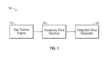
- the system 10 includes a gas turbine engine 12 that provides rotational drive to an integrated drive generator (IDG) 16 through an accessory drive gearbox 14 mounted on the gas turbine engine 12.
- IDG integrated drive generator
- the accessory drive gearbox is coupled to a spool of the engine 12, and the speed of the spool varies throughout the entire engine operation.
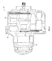
- FIG. 2 An example of an IDG 16 including a housing 18 is shown in FIG. 2 .
- the IDG 16 includes an input shaft configured to receive rotational drive from the accessory drive gearbox 14. The rotational speed of the input shaft varies depending upon the operation of the engine.
- a hydraulic unit 32 cooperates with the differential assembly 28 to convert the variable rotational speed from the input shaft to a fixed rotational output speed to the generator 24.
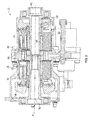
- the hydraulic unit 32 includes a variable displacement hydraulic pump 34 and a fixed displacement hydraulic motor 36.
- the pump 34 and motor 36 have respective cylinder blocks 38 and 40 which are arranged for rotation about a common axis A within a housing 42 on opposite sides of a stationary port plate 44 of the hydraulic unit 32.
- the port plate 44 is formed with apertures 46 through which hydraulic fluid communication between the pump 34 and the motor 36 is established during normal operation of the hydraulic unit 32.
- a biasing mechanism 48 resiliently biases the cylinder blocks 38, 40 in the direction of the port plate 44.
- the operation of the hydraulic unit 32 in an IDG 16 of an aircraft involves transmission of torque from an engine of the airplane to an input, which rotates the input shaft 50 of the hydraulic unit 32 about axis A.
- the cylinder block 38 of the pump 34 is connected to the input shaft 50 for rotation therewith. Pistons 52 within the cylinder block 38 of the pump 34 are displaced during this rotation an amount which is a function of the setting of a variable swash plate 54 of the pump 34.
- Hydraulic fluid under pressure from the pump 34 is delivered to the hydraulic motor 36 through the port plate 44 for rotating the cylinder block 40 and an output shaft 56 to which it is fixedly connected.
- the swash plate 58 of the motor 36 is fixed so that the operating speed of the motor 36 is a function of the displacement of the pump 34.
- the rotary output from output shaft 56 is added to or subtracted from the rotary motion from the engine through the conventional differential gearing of an IDG 16 for operating an electrical generator at a substantially constant rotational speed. That is, since the speed of the rotation from the airplane engine to the input 50 of the hydraulic unit 32 will vary, the position of the variable swash plate 54 is adjusted in response to these detected speed variations for providing the necessary reduction or increase in this speed for obtaining the desired constant output speed to the generator.
- hydraulic unit illustrated and described herein refers to the variable unit as a pump and the fixed unit as a motor
- hydraulic units having other configurations, such as where the variable unit functions as a motor and the hydraulic unit operates as a pump for example, are within the scope of the invention.
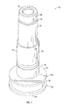
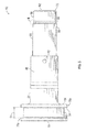
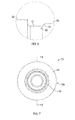
- the shaft 50 includes a substantially elongated non-uniform body 60 having a first end 62 and a second, opposite end 64.
- a relief 66 is formed about the circumference of the shaft 50 near the first end 62 to define a first portion 68 of the body 60 extending there between.
- the first portion 68 of the body 60 has an outer diameter of about .6680 +.000 -.0005 inches (1.697 +.000 -.0013 centimeters).
- the first end 62 of the shaft 50 may include a chamfer 70 extending outwardly at about a 45° ⁇ 2° angle such that the first end 62 of the body 60 has a diameter of about .615 ⁇ .015 inches (1.562 ⁇ .0381 cm).
- the relief 66 may be positioned such that a distance from the first end 62 of the shaft 50 to a far end 72 of the relief 66 is about .380 ⁇ .010 inches (.965 ⁇ .0254 cm)
- the relief 66 has a maximum length extending parallel to a longitudinal axis A of the shaft of .060 inches (.1524 cm).
- the height or thickness of the relief 66 extending perpendicular to the longitudinal axis is about .010 ⁇ .005 inches (.0254 ⁇ .0127 cm).
- the end 74 of the relief 66 closest to the first end 62 of the shaft 50 may include an angle and the opposite end 72 of the relief 66 may include a radius.
- the angle is 45° ⁇ 10° and the radius is about .010 +.010, -.005 inches (.0254 +.0254, -.0127 cm).
- flange 76a, 76b Located at the second end 64 of the shaft 60 is a pair of identical flanges 76a, 76b, separated from one another by a distance D.
- the distance D between the first and second flange 76a, 76b is about .3162 inches (.8031 cm).
- Each flange 76a, 76b may be configured to have an axial length of about .085 ⁇ .010 inches (.216 ⁇ .0254 cm) and an outer diameter of about 1.359 inches (3.452 cm).
- the distance from the first end 62 of the shaft 50 to an opposite surface 78 of the second flange 76b is about 2.875 ⁇ .005 inches (7.303 ⁇ .0127 cm).
- the portion 80 of the shaft located between the first and second flanges 76a, 76b is configured to receive a bearing (not shown).
- the portion 80 of the shaft 50 located between the flanges 76a, 76b has an outer diameter of about 1.2013 inches (3.051 cm).
- a second portion 82 Arranged generally adjacent the relief 66, opposite the first portion 68 of the body 60 is a second portion 82.
- the second portion 82 of the body 60 has an outer diameter of about .703 ⁇ .010 inches (1.786 ⁇ .0254 cm).
- the third portion 86 extends an axial distance of about .563 ⁇ .030 inches (1.430 ⁇ .0762 cm) from surface 78 of the flange 76b and has an outer diameter of about .810 ⁇ .010 inches (2.057 ⁇ .0254 cm).
- a radius of about .094 ⁇ .010 inches (.238 ⁇ .0254 cm) may be formed at the interface between the flange 76b and the third portion 86.
- a plurality of first splines 88 may be formed into an exterior surface of the body 60 between the second portion 82 and the third portion 86.
- the first splines 88 are constructed as detailed in Table 1.
- the plurality of first splines 88 may be positioned along the body 60 of the shaft 50 such that a distance from a first end 90 of the first splines 88 to surface 78 of the second flange 76b is about 1.522 ⁇ .010 inches (3.866 ⁇ .0254 cm).
- a length of the plurality of first splines 88 maybe about .676 ⁇ .035 inches (1.717 ⁇ .089 cm).
- Table 1 External Spline Dimensions Data for External Involute Splines Type Fillet Root Side Fit Class A Pitch Diameter .7750 in No. of Teeth 31 Pitch Fraction 40/80 Base Circle Diameter .6712in Pressure Angle 30° Max Form Diameter .7500 in Min Dim. Over Two Wires .8436in Wire Size 0.048 in Major Diam .800 +.000 -.005 in Minor Diam .725 +.000 -.012 in Additional Reqs when Max effective size is not gaged Max Profile Variation .0010 in Max Lead Variation .0003 in Circular Tooth Thickness Max Actual .0371 in Circular Tooth Thickness Min Actual .0361 in Max Diam Over Two Wires .8452 in
- a through hole 92 used to supply lubricant to the shaft 50 may be formed in the portion of the body 60 including the first splines 88.
- the through hole 92 has a diameter of about .095 ⁇ .005 inches (.2413 ⁇ .0127cm) and a center of the through hole 92 is located a distance of about 1.475 inches (3.747 cm) from the first end 62 of the shaft 50.
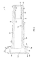
- variable shaft 50 is substantially hollow.
- a first hollow portion 100 extends inwardly from adjacent the second end 64 of the shaft 50.
- the first hollow portion 100 has an axial length of .364 ⁇ .010 inches (.925 ⁇ .0254 cm) and an inner diameter of .938 ⁇ .010 inches (2.383 ⁇ .0254 cm).
- a radius of .060 ⁇ .010 inches (.152 ⁇ .0254 cm) may be formed at the interface between the first hollow portion 100 the adjacent wall of the shaft 50.
- a chamfer 102 may be formed at the interior of the second end 64 of the shaft 50. In one embodiment, the chamfer 102 has an angle of 30° ⁇ 5° such that an outer diameter of the chamfer at the second end of the shaft is about 1.031 ⁇ .015 inches (2.619 ⁇ .038 cm).
- a second hollow portion 104 extends from the first hollow portion over an axial length of the shaft 50, such as to the second portion 82 of the body for example.
- an inner diameter of the second hollow portion 104 is .517 ⁇ .010 inches (1.313 ⁇ .0254 cm).
- a third hollow portion 106 extends from the second hollow portion 104 to the first end 62 of the shaft 50.
- a plurality of second splines 108 may be integrally formed with shaft 50 to define the third hollow portion 106.
- an end 110 of the second splines 108 is spaced from the second end 64 of the shaft 50 at a distance of about 2.351 ⁇ .015 inches (5.972 ⁇ .038 cm).
- the plurality of second splines 108 is constructed as detailed in Table 2.
- Table 2 Internal Spline Dimensions Data for Internal Involute Splines Type Fillet Root Side Fit Class D Pitch Diameter .4000 in No. of Teeth 16 Pitch Fraction 40/80 Base Circle Diameter .3464 in Pressure Angle 30° Max Form Diameter .4250 in Min Dim.
- a chamfer 112 may similarly be formed at the interior of the first end 62 of the shaft 50.
- the chamfer 112 has an angle of 30° ⁇ 5° such that an outer diameter of the chamfer 112 at the first end 62 of the shaft 50 is about .438 ⁇ .015 inches (1.113 ⁇ .038 cm).
Landscapes
- Engineering & Computer Science (AREA)
- General Engineering & Computer Science (AREA)
- Mechanical Engineering (AREA)
- Chemical & Material Sciences (AREA)
- Combustion & Propulsion (AREA)
- Ocean & Marine Engineering (AREA)
- Shafts, Cranks, Connecting Bars, And Related Bearings (AREA)
Applications Claiming Priority (1)
| Application Number | Priority Date | Filing Date | Title |
|---|---|---|---|
| US14/551,990 US9482265B2 (en) | 2014-11-24 | 2014-11-24 | Variable shaft for hydraulic unit |
Publications (2)
| Publication Number | Publication Date |
|---|---|
| EP3023616A1 true EP3023616A1 (de) | 2016-05-25 |
| EP3023616B1 EP3023616B1 (de) | 2020-01-22 |
Family
ID=54754452
Family Applications (1)
| Application Number | Title | Priority Date | Filing Date |
|---|---|---|---|
| EP15195969.9A Active EP3023616B1 (de) | 2014-11-24 | 2015-11-24 | Variable welle für hydraulikeinheit |
Country Status (2)
| Country | Link |
|---|---|
| US (1) | US9482265B2 (de) |
| EP (1) | EP3023616B1 (de) |
Cited By (1)
| Publication number | Priority date | Publication date | Assignee | Title |
|---|---|---|---|---|
| EP3514398A1 (de) * | 2018-01-11 | 2019-07-24 | Hamilton Sundstrand Corporation | Innere lagerbuchse einer festen blockwelle für einen integrierten antriebsgenerator |
Families Citing this family (5)
| Publication number | Priority date | Publication date | Assignee | Title |
|---|---|---|---|---|
| US9488215B2 (en) * | 2014-11-24 | 2016-11-08 | Hamilton Sundstrand Corporation | Fixed shaft for hydraulic unit |
| US10273883B2 (en) * | 2016-02-26 | 2019-04-30 | The Boeing Company | Engine accessory drives systems and methods |
| US10670126B2 (en) * | 2018-01-11 | 2020-06-02 | Hamilton Sundstrand Corporation | Variable block shaft for integrated drive generator |
| US10995675B2 (en) | 2019-02-19 | 2021-05-04 | Pratt & Whitney Canada Corp. | Gas turbine engine with accessory gearbox |
| US12498036B2 (en) * | 2023-03-02 | 2025-12-16 | Hamilton Sundstrand Corporation | IDG governor rotating sleeve |
Citations (3)
| Publication number | Priority date | Publication date | Assignee | Title |
|---|---|---|---|---|
| US4734590A (en) * | 1986-12-30 | 1988-03-29 | Sundstrand Corporation | Integrated drive generator with common center line |
| US5014513A (en) * | 1989-08-30 | 1991-05-14 | Sundstrand Corporation | Self-sealing transfer tube for port plate |
| US5247794A (en) * | 1990-09-11 | 1993-09-28 | Sundstrand Corporation | Cylinder block positive hold-down for cold start-up |
Family Cites Families (4)
| Publication number | Priority date | Publication date | Assignee | Title |
|---|---|---|---|---|
| DE943866C (de) * | 1952-10-03 | 1956-06-01 | Licentia Gmbh | Schwingungsfreie Lagerung und Antrieb einer Welle, Spindel, Achse u. dgl. fuer hohe Drehzahlen |
| US2848882A (en) * | 1955-11-25 | 1958-08-26 | Gen Motors Corp | Drive noise insulating means |
| US4252035A (en) * | 1978-08-11 | 1981-02-24 | Sundstrand Corporation | Integrated drive-generator system |
| US20140008170A1 (en) * | 2012-07-06 | 2014-01-09 | Henry R. Vanderzyden | Integrated drive generator disconnect assembly |
-
2014
- 2014-11-24 US US14/551,990 patent/US9482265B2/en active Active
-
2015
- 2015-11-24 EP EP15195969.9A patent/EP3023616B1/de active Active
Patent Citations (3)
| Publication number | Priority date | Publication date | Assignee | Title |
|---|---|---|---|---|
| US4734590A (en) * | 1986-12-30 | 1988-03-29 | Sundstrand Corporation | Integrated drive generator with common center line |
| US5014513A (en) * | 1989-08-30 | 1991-05-14 | Sundstrand Corporation | Self-sealing transfer tube for port plate |
| US5247794A (en) * | 1990-09-11 | 1993-09-28 | Sundstrand Corporation | Cylinder block positive hold-down for cold start-up |
Cited By (2)
| Publication number | Priority date | Publication date | Assignee | Title |
|---|---|---|---|---|
| EP3514398A1 (de) * | 2018-01-11 | 2019-07-24 | Hamilton Sundstrand Corporation | Innere lagerbuchse einer festen blockwelle für einen integrierten antriebsgenerator |
| US10436251B2 (en) | 2018-01-11 | 2019-10-08 | Hamilton Sundstrand Corporation | Fixed block shaft inner bearing race for integrated drive generator |
Also Published As
| Publication number | Publication date |
|---|---|
| US9482265B2 (en) | 2016-11-01 |
| US20160146244A1 (en) | 2016-05-26 |
| EP3023616B1 (de) | 2020-01-22 |
Similar Documents
| Publication | Publication Date | Title |
|---|---|---|
| EP3023616B1 (de) | Variable welle für hydraulikeinheit | |
| EP3023651B1 (de) | Festwelle für hydraulikeinheit | |
| US20160201697A1 (en) | Variable wobbler for hydraulic unit | |
| EP3034900B1 (de) | Feste koaxiale welle für ein hydraulikaggregat | |
| EP3081824A1 (de) | Abschaltwelle für einen integrierten antriebsgenerator | |
| US10451163B2 (en) | Trim ring gear for integrated drive generator | |
| EP3514398A1 (de) | Innere lagerbuchse einer festen blockwelle für einen integrierten antriebsgenerator | |
| EP3467349B1 (de) | Hilfsantriebsgetriebe für integrierten antriebsgenerator | |
| US9863408B2 (en) | Slipper retainer for hydraulic unit | |
| US9435378B1 (en) | Roller bearing outer race for hydraulic unit | |
| EP3511595B1 (de) | Variable blockwelle für einen integrierten antriebsgenerator | |
| EP3511594A1 (de) | Feste blockwelle für einen integrierten antriebsgenerator | |
| EP3502514B1 (de) | Abgangszahnkranz für integrierten antriebsgenerator | |
| EP3489532B1 (de) | Verschleissring für einen integrierten antriebsgenerator | |
| EP3045722A1 (de) | Fester wobbler für hydraulikbaugruppe | |
| EP3045720B1 (de) | Gleitschuhhalterkugel für hydraulikeinheit | |
| EP3673188B1 (de) | Exzentergetriebe mit reduziertem spiel | |
| EP3663565A1 (de) | Getriebewellenanordnung für eine hydraulische einheit | |
| EP3061965B1 (de) | Wälzlageraussenring einer hydraulikeinheit | |
| US20190203820A1 (en) | Governor drive gear for integrated drive generator |
Legal Events
| Date | Code | Title | Description |
|---|---|---|---|
| AK | Designated contracting states |
Kind code of ref document: A1 Designated state(s): AL AT BE BG CH CY CZ DE DK EE ES FI FR GB GR HR HU IE IS IT LI LT LU LV MC MK MT NL NO PL PT RO RS SE SI SK SM TR |
|
| AX | Request for extension of the european patent |
Extension state: BA ME |
|
| PUAI | Public reference made under article 153(3) epc to a published international application that has entered the european phase |
Free format text: ORIGINAL CODE: 0009012 |
|
| STAA | Information on the status of an ep patent application or granted ep patent |
Free format text: STATUS: REQUEST FOR EXAMINATION WAS MADE |
|
| 17P | Request for examination filed |
Effective date: 20161117 |
|
| RBV | Designated contracting states (corrected) |
Designated state(s): AL AT BE BG CH CY CZ DE DK EE ES FI FR GB GR HR HU IE IS IT LI LT LU LV MC MK MT NL NO PL PT RO RS SE SI SK SM TR |
|
| STAA | Information on the status of an ep patent application or granted ep patent |
Free format text: STATUS: EXAMINATION IS IN PROGRESS |
|
| 17Q | First examination report despatched |
Effective date: 20170821 |
|
| GRAP | Despatch of communication of intention to grant a patent |
Free format text: ORIGINAL CODE: EPIDOSNIGR1 |
|
| STAA | Information on the status of an ep patent application or granted ep patent |
Free format text: STATUS: GRANT OF PATENT IS INTENDED |
|
| INTG | Intention to grant announced |
Effective date: 20190814 |
|
| GRAS | Grant fee paid |
Free format text: ORIGINAL CODE: EPIDOSNIGR3 |
|
| GRAA | (expected) grant |
Free format text: ORIGINAL CODE: 0009210 |
|
| STAA | Information on the status of an ep patent application or granted ep patent |
Free format text: STATUS: THE PATENT HAS BEEN GRANTED |
|
| AK | Designated contracting states |
Kind code of ref document: B1 Designated state(s): AL AT BE BG CH CY CZ DE DK EE ES FI FR GB GR HR HU IE IS IT LI LT LU LV MC MK MT NL NO PL PT RO RS SE SI SK SM TR |
|
| REG | Reference to a national code |
Ref country code: GB Ref legal event code: FG4D |
|
| REG | Reference to a national code |
Ref country code: CH Ref legal event code: EP |
|
| REG | Reference to a national code |
Ref country code: AT Ref legal event code: REF Ref document number: 1227050 Country of ref document: AT Kind code of ref document: T Effective date: 20200215 |
|
| REG | Reference to a national code |
Ref country code: IE Ref legal event code: FG4D |
|
| REG | Reference to a national code |
Ref country code: DE Ref legal event code: R096 Ref document number: 602015045912 Country of ref document: DE |
|
| REG | Reference to a national code |
Ref country code: NL Ref legal event code: MP Effective date: 20200122 |
|
| REG | Reference to a national code |
Ref country code: LT Ref legal event code: MG4D |
|
| PG25 | Lapsed in a contracting state [announced via postgrant information from national office to epo] |
Ref country code: NL Free format text: LAPSE BECAUSE OF FAILURE TO SUBMIT A TRANSLATION OF THE DESCRIPTION OR TO PAY THE FEE WITHIN THE PRESCRIBED TIME-LIMIT Effective date: 20200122 Ref country code: NO Free format text: LAPSE BECAUSE OF FAILURE TO SUBMIT A TRANSLATION OF THE DESCRIPTION OR TO PAY THE FEE WITHIN THE PRESCRIBED TIME-LIMIT Effective date: 20200422 Ref country code: FI Free format text: LAPSE BECAUSE OF FAILURE TO SUBMIT A TRANSLATION OF THE DESCRIPTION OR TO PAY THE FEE WITHIN THE PRESCRIBED TIME-LIMIT Effective date: 20200122 Ref country code: RS Free format text: LAPSE BECAUSE OF FAILURE TO SUBMIT A TRANSLATION OF THE DESCRIPTION OR TO PAY THE FEE WITHIN THE PRESCRIBED TIME-LIMIT Effective date: 20200122 Ref country code: PT Free format text: LAPSE BECAUSE OF FAILURE TO SUBMIT A TRANSLATION OF THE DESCRIPTION OR TO PAY THE FEE WITHIN THE PRESCRIBED TIME-LIMIT Effective date: 20200614 |
|
| PG25 | Lapsed in a contracting state [announced via postgrant information from national office to epo] |
Ref country code: LV Free format text: LAPSE BECAUSE OF FAILURE TO SUBMIT A TRANSLATION OF THE DESCRIPTION OR TO PAY THE FEE WITHIN THE PRESCRIBED TIME-LIMIT Effective date: 20200122 Ref country code: SE Free format text: LAPSE BECAUSE OF FAILURE TO SUBMIT A TRANSLATION OF THE DESCRIPTION OR TO PAY THE FEE WITHIN THE PRESCRIBED TIME-LIMIT Effective date: 20200122 Ref country code: IS Free format text: LAPSE BECAUSE OF FAILURE TO SUBMIT A TRANSLATION OF THE DESCRIPTION OR TO PAY THE FEE WITHIN THE PRESCRIBED TIME-LIMIT Effective date: 20200522 Ref country code: HR Free format text: LAPSE BECAUSE OF FAILURE TO SUBMIT A TRANSLATION OF THE DESCRIPTION OR TO PAY THE FEE WITHIN THE PRESCRIBED TIME-LIMIT Effective date: 20200122 Ref country code: GR Free format text: LAPSE BECAUSE OF FAILURE TO SUBMIT A TRANSLATION OF THE DESCRIPTION OR TO PAY THE FEE WITHIN THE PRESCRIBED TIME-LIMIT Effective date: 20200423 Ref country code: BG Free format text: LAPSE BECAUSE OF FAILURE TO SUBMIT A TRANSLATION OF THE DESCRIPTION OR TO PAY THE FEE WITHIN THE PRESCRIBED TIME-LIMIT Effective date: 20200422 |
|
| REG | Reference to a national code |
Ref country code: DE Ref legal event code: R097 Ref document number: 602015045912 Country of ref document: DE |
|
| PG25 | Lapsed in a contracting state [announced via postgrant information from national office to epo] |
Ref country code: SM Free format text: LAPSE BECAUSE OF FAILURE TO SUBMIT A TRANSLATION OF THE DESCRIPTION OR TO PAY THE FEE WITHIN THE PRESCRIBED TIME-LIMIT Effective date: 20200122 Ref country code: SK Free format text: LAPSE BECAUSE OF FAILURE TO SUBMIT A TRANSLATION OF THE DESCRIPTION OR TO PAY THE FEE WITHIN THE PRESCRIBED TIME-LIMIT Effective date: 20200122 Ref country code: EE Free format text: LAPSE BECAUSE OF FAILURE TO SUBMIT A TRANSLATION OF THE DESCRIPTION OR TO PAY THE FEE WITHIN THE PRESCRIBED TIME-LIMIT Effective date: 20200122 Ref country code: CZ Free format text: LAPSE BECAUSE OF FAILURE TO SUBMIT A TRANSLATION OF THE DESCRIPTION OR TO PAY THE FEE WITHIN THE PRESCRIBED TIME-LIMIT Effective date: 20200122 Ref country code: RO Free format text: LAPSE BECAUSE OF FAILURE TO SUBMIT A TRANSLATION OF THE DESCRIPTION OR TO PAY THE FEE WITHIN THE PRESCRIBED TIME-LIMIT Effective date: 20200122 Ref country code: ES Free format text: LAPSE BECAUSE OF FAILURE TO SUBMIT A TRANSLATION OF THE DESCRIPTION OR TO PAY THE FEE WITHIN THE PRESCRIBED TIME-LIMIT Effective date: 20200122 Ref country code: LT Free format text: LAPSE BECAUSE OF FAILURE TO SUBMIT A TRANSLATION OF THE DESCRIPTION OR TO PAY THE FEE WITHIN THE PRESCRIBED TIME-LIMIT Effective date: 20200122 Ref country code: DK Free format text: LAPSE BECAUSE OF FAILURE TO SUBMIT A TRANSLATION OF THE DESCRIPTION OR TO PAY THE FEE WITHIN THE PRESCRIBED TIME-LIMIT Effective date: 20200122 |
|
| REG | Reference to a national code |
Ref country code: AT Ref legal event code: MK05 Ref document number: 1227050 Country of ref document: AT Kind code of ref document: T Effective date: 20200122 |
|
| PLBE | No opposition filed within time limit |
Free format text: ORIGINAL CODE: 0009261 |
|
| STAA | Information on the status of an ep patent application or granted ep patent |
Free format text: STATUS: NO OPPOSITION FILED WITHIN TIME LIMIT |
|
| 26N | No opposition filed |
Effective date: 20201023 |
|
| PG25 | Lapsed in a contracting state [announced via postgrant information from national office to epo] |
Ref country code: IT Free format text: LAPSE BECAUSE OF FAILURE TO SUBMIT A TRANSLATION OF THE DESCRIPTION OR TO PAY THE FEE WITHIN THE PRESCRIBED TIME-LIMIT Effective date: 20200122 Ref country code: AT Free format text: LAPSE BECAUSE OF FAILURE TO SUBMIT A TRANSLATION OF THE DESCRIPTION OR TO PAY THE FEE WITHIN THE PRESCRIBED TIME-LIMIT Effective date: 20200122 |
|
| PG25 | Lapsed in a contracting state [announced via postgrant information from national office to epo] |
Ref country code: SI Free format text: LAPSE BECAUSE OF FAILURE TO SUBMIT A TRANSLATION OF THE DESCRIPTION OR TO PAY THE FEE WITHIN THE PRESCRIBED TIME-LIMIT Effective date: 20200122 Ref country code: PL Free format text: LAPSE BECAUSE OF FAILURE TO SUBMIT A TRANSLATION OF THE DESCRIPTION OR TO PAY THE FEE WITHIN THE PRESCRIBED TIME-LIMIT Effective date: 20200122 |
|
| REG | Reference to a national code |
Ref country code: DE Ref legal event code: R119 Ref document number: 602015045912 Country of ref document: DE |
|
| PG25 | Lapsed in a contracting state [announced via postgrant information from national office to epo] |
Ref country code: MC Free format text: LAPSE BECAUSE OF FAILURE TO SUBMIT A TRANSLATION OF THE DESCRIPTION OR TO PAY THE FEE WITHIN THE PRESCRIBED TIME-LIMIT Effective date: 20200122 |
|
| REG | Reference to a national code |
Ref country code: CH Ref legal event code: PL |
|
| PG25 | Lapsed in a contracting state [announced via postgrant information from national office to epo] |
Ref country code: LU Free format text: LAPSE BECAUSE OF NON-PAYMENT OF DUE FEES Effective date: 20201124 |
|
| REG | Reference to a national code |
Ref country code: BE Ref legal event code: MM Effective date: 20201130 |
|
| PG25 | Lapsed in a contracting state [announced via postgrant information from national office to epo] |
Ref country code: LI Free format text: LAPSE BECAUSE OF NON-PAYMENT OF DUE FEES Effective date: 20201130 Ref country code: CH Free format text: LAPSE BECAUSE OF NON-PAYMENT OF DUE FEES Effective date: 20201130 |
|
| PG25 | Lapsed in a contracting state [announced via postgrant information from national office to epo] |
Ref country code: IE Free format text: LAPSE BECAUSE OF NON-PAYMENT OF DUE FEES Effective date: 20201124 |
|
| PG25 | Lapsed in a contracting state [announced via postgrant information from national office to epo] |
Ref country code: DE Free format text: LAPSE BECAUSE OF NON-PAYMENT OF DUE FEES Effective date: 20210601 |
|
| PG25 | Lapsed in a contracting state [announced via postgrant information from national office to epo] |
Ref country code: TR Free format text: LAPSE BECAUSE OF FAILURE TO SUBMIT A TRANSLATION OF THE DESCRIPTION OR TO PAY THE FEE WITHIN THE PRESCRIBED TIME-LIMIT Effective date: 20200122 Ref country code: MT Free format text: LAPSE BECAUSE OF FAILURE TO SUBMIT A TRANSLATION OF THE DESCRIPTION OR TO PAY THE FEE WITHIN THE PRESCRIBED TIME-LIMIT Effective date: 20200122 Ref country code: CY Free format text: LAPSE BECAUSE OF FAILURE TO SUBMIT A TRANSLATION OF THE DESCRIPTION OR TO PAY THE FEE WITHIN THE PRESCRIBED TIME-LIMIT Effective date: 20200122 |
|
| PG25 | Lapsed in a contracting state [announced via postgrant information from national office to epo] |
Ref country code: MK Free format text: LAPSE BECAUSE OF FAILURE TO SUBMIT A TRANSLATION OF THE DESCRIPTION OR TO PAY THE FEE WITHIN THE PRESCRIBED TIME-LIMIT Effective date: 20200122 Ref country code: AL Free format text: LAPSE BECAUSE OF FAILURE TO SUBMIT A TRANSLATION OF THE DESCRIPTION OR TO PAY THE FEE WITHIN THE PRESCRIBED TIME-LIMIT Effective date: 20200122 |
|
| PG25 | Lapsed in a contracting state [announced via postgrant information from national office to epo] |
Ref country code: BE Free format text: LAPSE BECAUSE OF NON-PAYMENT OF DUE FEES Effective date: 20201130 |
|
| P01 | Opt-out of the competence of the unified patent court (upc) registered |
Effective date: 20230522 |
|
| PGFP | Annual fee paid to national office [announced via postgrant information from national office to epo] |
Ref country code: GB Payment date: 20251023 Year of fee payment: 11 |
|
| PGFP | Annual fee paid to national office [announced via postgrant information from national office to epo] |
Ref country code: FR Payment date: 20251022 Year of fee payment: 11 |