EP3663565A1 - Getriebewellenanordnung für eine hydraulische einheit - Google Patents
Getriebewellenanordnung für eine hydraulische einheit Download PDFInfo
- Publication number
- EP3663565A1 EP3663565A1 EP19213871.7A EP19213871A EP3663565A1 EP 3663565 A1 EP3663565 A1 EP 3663565A1 EP 19213871 A EP19213871 A EP 19213871A EP 3663565 A1 EP3663565 A1 EP 3663565A1
- Authority
- EP
- European Patent Office
- Prior art keywords
- gear shaft
- main body
- body portion
- roller bearing
- assembly
- Prior art date
- Legal status (The legal status is an assumption and is not a legal conclusion. Google has not performed a legal analysis and makes no representation as to the accuracy of the status listed.)
- Withdrawn
Links
- 238000005096 rolling process Methods 0.000 claims abstract description 4
- 238000006073 displacement reaction Methods 0.000 description 3
- 239000013585 weight reducing agent Substances 0.000 description 3
- 239000012530 fluid Substances 0.000 description 2
- 230000000712 assembly Effects 0.000 description 1
- 238000000429 assembly Methods 0.000 description 1
- 230000005540 biological transmission Effects 0.000 description 1
- 230000008859 change Effects 0.000 description 1
- 238000004891 communication Methods 0.000 description 1
- 230000002706 hydrostatic effect Effects 0.000 description 1
- 230000006872 improvement Effects 0.000 description 1
- 238000012423 maintenance Methods 0.000 description 1
- 238000012986 modification Methods 0.000 description 1
- 230000004048 modification Effects 0.000 description 1
- 238000010248 power generation Methods 0.000 description 1
- 230000009467 reduction Effects 0.000 description 1
- 230000004044 response Effects 0.000 description 1
Images


Classifications
-
- F—MECHANICAL ENGINEERING; LIGHTING; HEATING; WEAPONS; BLASTING
- F16—ENGINEERING ELEMENTS AND UNITS; GENERAL MEASURES FOR PRODUCING AND MAINTAINING EFFECTIVE FUNCTIONING OF MACHINES OR INSTALLATIONS; THERMAL INSULATION IN GENERAL
- F16C—SHAFTS; FLEXIBLE SHAFTS; ELEMENTS OR CRANKSHAFT MECHANISMS; ROTARY BODIES OTHER THAN GEARING ELEMENTS; BEARINGS
- F16C19/00—Bearings with rolling contact, for exclusively rotary movement
- F16C19/22—Bearings with rolling contact, for exclusively rotary movement with bearing rollers essentially of the same size in one or more circular rows, e.g. needle bearings
- F16C19/24—Bearings with rolling contact, for exclusively rotary movement with bearing rollers essentially of the same size in one or more circular rows, e.g. needle bearings for radial load mainly
- F16C19/26—Bearings with rolling contact, for exclusively rotary movement with bearing rollers essentially of the same size in one or more circular rows, e.g. needle bearings for radial load mainly with a single row of rollers
-
- F—MECHANICAL ENGINEERING; LIGHTING; HEATING; WEAPONS; BLASTING
- F02—COMBUSTION ENGINES; HOT-GAS OR COMBUSTION-PRODUCT ENGINE PLANTS
- F02C—GAS-TURBINE PLANTS; AIR INTAKES FOR JET-PROPULSION PLANTS; CONTROLLING FUEL SUPPLY IN AIR-BREATHING JET-PROPULSION PLANTS
- F02C7/00—Features, components parts, details or accessories, not provided for in, or of interest apart form groups F02C1/00 - F02C6/00; Air intakes for jet-propulsion plants
- F02C7/32—Arrangement, mounting, or driving, of auxiliaries
-
- F—MECHANICAL ENGINEERING; LIGHTING; HEATING; WEAPONS; BLASTING
- F16—ENGINEERING ELEMENTS AND UNITS; GENERAL MEASURES FOR PRODUCING AND MAINTAINING EFFECTIVE FUNCTIONING OF MACHINES OR INSTALLATIONS; THERMAL INSULATION IN GENERAL
- F16C—SHAFTS; FLEXIBLE SHAFTS; ELEMENTS OR CRANKSHAFT MECHANISMS; ROTARY BODIES OTHER THAN GEARING ELEMENTS; BEARINGS
- F16C3/00—Shafts; Axles; Cranks; Eccentrics
- F16C3/02—Shafts; Axles
-
- F—MECHANICAL ENGINEERING; LIGHTING; HEATING; WEAPONS; BLASTING
- F16—ENGINEERING ELEMENTS AND UNITS; GENERAL MEASURES FOR PRODUCING AND MAINTAINING EFFECTIVE FUNCTIONING OF MACHINES OR INSTALLATIONS; THERMAL INSULATION IN GENERAL
- F16C—SHAFTS; FLEXIBLE SHAFTS; ELEMENTS OR CRANKSHAFT MECHANISMS; ROTARY BODIES OTHER THAN GEARING ELEMENTS; BEARINGS
- F16C33/00—Parts of bearings; Special methods for making bearings or parts thereof
- F16C33/30—Parts of ball or roller bearings
- F16C33/58—Raceways; Race rings
- F16C33/581—Raceways; Race rings integral with other parts, e.g. with housings or machine elements such as shafts or gear wheels
-
- F—MECHANICAL ENGINEERING; LIGHTING; HEATING; WEAPONS; BLASTING
- F16—ENGINEERING ELEMENTS AND UNITS; GENERAL MEASURES FOR PRODUCING AND MAINTAINING EFFECTIVE FUNCTIONING OF MACHINES OR INSTALLATIONS; THERMAL INSULATION IN GENERAL
- F16H—GEARING
- F16H39/00—Rotary fluid gearing using pumps and motors of the volumetric type, i.e. passing a predetermined volume of fluid per revolution
- F16H39/04—Rotary fluid gearing using pumps and motors of the volumetric type, i.e. passing a predetermined volume of fluid per revolution with liquid motor and pump combined in one unit
- F16H39/06—Rotary fluid gearing using pumps and motors of the volumetric type, i.e. passing a predetermined volume of fluid per revolution with liquid motor and pump combined in one unit pump and motor being of the same type
- F16H39/08—Rotary fluid gearing using pumps and motors of the volumetric type, i.e. passing a predetermined volume of fluid per revolution with liquid motor and pump combined in one unit pump and motor being of the same type each with one main shaft and provided with pistons reciprocating in cylinders
- F16H39/10—Rotary fluid gearing using pumps and motors of the volumetric type, i.e. passing a predetermined volume of fluid per revolution with liquid motor and pump combined in one unit pump and motor being of the same type each with one main shaft and provided with pistons reciprocating in cylinders with cylinders arranged around, and parallel or approximately parallel to the main axis of the gearing
- F16H39/14—Rotary fluid gearing using pumps and motors of the volumetric type, i.e. passing a predetermined volume of fluid per revolution with liquid motor and pump combined in one unit pump and motor being of the same type each with one main shaft and provided with pistons reciprocating in cylinders with cylinders arranged around, and parallel or approximately parallel to the main axis of the gearing with cylinders carried in rotary cylinder blocks or cylinder-bearing members
-
- F—MECHANICAL ENGINEERING; LIGHTING; HEATING; WEAPONS; BLASTING
- F16—ENGINEERING ELEMENTS AND UNITS; GENERAL MEASURES FOR PRODUCING AND MAINTAINING EFFECTIVE FUNCTIONING OF MACHINES OR INSTALLATIONS; THERMAL INSULATION IN GENERAL
- F16H—GEARING
- F16H55/00—Elements with teeth or friction surfaces for conveying motion; Worms, pulleys or sheaves for gearing mechanisms
- F16H55/02—Toothed members; Worms
- F16H55/17—Toothed wheels
-
- F—MECHANICAL ENGINEERING; LIGHTING; HEATING; WEAPONS; BLASTING
- F16—ENGINEERING ELEMENTS AND UNITS; GENERAL MEASURES FOR PRODUCING AND MAINTAINING EFFECTIVE FUNCTIONING OF MACHINES OR INSTALLATIONS; THERMAL INSULATION IN GENERAL
- F16H—GEARING
- F16H57/00—General details of gearing
- F16H57/0018—Shaft assemblies for gearings
- F16H57/0025—Shaft assemblies for gearings with gearing elements rigidly connected to a shaft, e.g. securing gears or pulleys by specially adapted splines, keys or methods
-
- F—MECHANICAL ENGINEERING; LIGHTING; HEATING; WEAPONS; BLASTING
- F16—ENGINEERING ELEMENTS AND UNITS; GENERAL MEASURES FOR PRODUCING AND MAINTAINING EFFECTIVE FUNCTIONING OF MACHINES OR INSTALLATIONS; THERMAL INSULATION IN GENERAL
- F16H—GEARING
- F16H57/00—General details of gearing
- F16H57/02—Gearboxes; Mounting gearing therein
- F16H57/021—Shaft support structures, e.g. partition walls, bearing eyes, casing walls or covers with bearings
-
- F—MECHANICAL ENGINEERING; LIGHTING; HEATING; WEAPONS; BLASTING
- F03—MACHINES OR ENGINES FOR LIQUIDS; WIND, SPRING, OR WEIGHT MOTORS; PRODUCING MECHANICAL POWER OR A REACTIVE PROPULSIVE THRUST, NOT OTHERWISE PROVIDED FOR
- F03C—POSITIVE-DISPLACEMENT ENGINES DRIVEN BY LIQUIDS
- F03C1/00—Reciprocating-piston liquid engines
- F03C1/02—Reciprocating-piston liquid engines with multiple-cylinders, characterised by the number or arrangement of cylinders
- F03C1/06—Reciprocating-piston liquid engines with multiple-cylinders, characterised by the number or arrangement of cylinders with cylinder axes generally coaxial with, or parallel or inclined to, main shaft axis
- F03C1/0636—Reciprocating-piston liquid engines with multiple-cylinders, characterised by the number or arrangement of cylinders with cylinder axes generally coaxial with, or parallel or inclined to, main shaft axis having rotary cylinder block
- F03C1/0644—Component parts
-
- F—MECHANICAL ENGINEERING; LIGHTING; HEATING; WEAPONS; BLASTING
- F03—MACHINES OR ENGINES FOR LIQUIDS; WIND, SPRING, OR WEIGHT MOTORS; PRODUCING MECHANICAL POWER OR A REACTIVE PROPULSIVE THRUST, NOT OTHERWISE PROVIDED FOR
- F03C—POSITIVE-DISPLACEMENT ENGINES DRIVEN BY LIQUIDS
- F03C1/00—Reciprocating-piston liquid engines
- F03C1/02—Reciprocating-piston liquid engines with multiple-cylinders, characterised by the number or arrangement of cylinders
- F03C1/06—Reciprocating-piston liquid engines with multiple-cylinders, characterised by the number or arrangement of cylinders with cylinder axes generally coaxial with, or parallel or inclined to, main shaft axis
- F03C1/0636—Reciprocating-piston liquid engines with multiple-cylinders, characterised by the number or arrangement of cylinders with cylinder axes generally coaxial with, or parallel or inclined to, main shaft axis having rotary cylinder block
- F03C1/0644—Component parts
- F03C1/0663—Casings, housings
-
- F—MECHANICAL ENGINEERING; LIGHTING; HEATING; WEAPONS; BLASTING
- F04—POSITIVE - DISPLACEMENT MACHINES FOR LIQUIDS; PUMPS FOR LIQUIDS OR ELASTIC FLUIDS
- F04B—POSITIVE-DISPLACEMENT MACHINES FOR LIQUIDS; PUMPS
- F04B1/00—Multi-cylinder machines or pumps characterised by number or arrangement of cylinders
- F04B1/12—Multi-cylinder machines or pumps characterised by number or arrangement of cylinders having cylinder axes coaxial with, or parallel or inclined to, main shaft axis
- F04B1/20—Multi-cylinder machines or pumps characterised by number or arrangement of cylinders having cylinder axes coaxial with, or parallel or inclined to, main shaft axis having rotary cylinder block
- F04B1/2014—Details or component parts
-
- F—MECHANICAL ENGINEERING; LIGHTING; HEATING; WEAPONS; BLASTING
- F04—POSITIVE - DISPLACEMENT MACHINES FOR LIQUIDS; PUMPS FOR LIQUIDS OR ELASTIC FLUIDS
- F04B—POSITIVE-DISPLACEMENT MACHINES FOR LIQUIDS; PUMPS
- F04B1/00—Multi-cylinder machines or pumps characterised by number or arrangement of cylinders
- F04B1/12—Multi-cylinder machines or pumps characterised by number or arrangement of cylinders having cylinder axes coaxial with, or parallel or inclined to, main shaft axis
- F04B1/20—Multi-cylinder machines or pumps characterised by number or arrangement of cylinders having cylinder axes coaxial with, or parallel or inclined to, main shaft axis having rotary cylinder block
- F04B1/2014—Details or component parts
- F04B1/2064—Housings
-
- F—MECHANICAL ENGINEERING; LIGHTING; HEATING; WEAPONS; BLASTING
- F05—INDEXING SCHEMES RELATING TO ENGINES OR PUMPS IN VARIOUS SUBCLASSES OF CLASSES F01-F04
- F05D—INDEXING SCHEME FOR ASPECTS RELATING TO NON-POSITIVE-DISPLACEMENT MACHINES OR ENGINES, GAS-TURBINES OR JET-PROPULSION PLANTS
- F05D2240/00—Components
- F05D2240/50—Bearings
- F05D2240/54—Radial bearings
-
- F—MECHANICAL ENGINEERING; LIGHTING; HEATING; WEAPONS; BLASTING
- F05—INDEXING SCHEMES RELATING TO ENGINES OR PUMPS IN VARIOUS SUBCLASSES OF CLASSES F01-F04
- F05D—INDEXING SCHEME FOR ASPECTS RELATING TO NON-POSITIVE-DISPLACEMENT MACHINES OR ENGINES, GAS-TURBINES OR JET-PROPULSION PLANTS
- F05D2240/00—Components
- F05D2240/60—Shafts
-
- F—MECHANICAL ENGINEERING; LIGHTING; HEATING; WEAPONS; BLASTING
- F05—INDEXING SCHEMES RELATING TO ENGINES OR PUMPS IN VARIOUS SUBCLASSES OF CLASSES F01-F04
- F05D—INDEXING SCHEME FOR ASPECTS RELATING TO NON-POSITIVE-DISPLACEMENT MACHINES OR ENGINES, GAS-TURBINES OR JET-PROPULSION PLANTS
- F05D2260/00—Function
- F05D2260/40—Transmission of power
- F05D2260/403—Transmission of power through the shape of the drive components
- F05D2260/4031—Transmission of power through the shape of the drive components as in toothed gearing
-
- F—MECHANICAL ENGINEERING; LIGHTING; HEATING; WEAPONS; BLASTING
- F16—ENGINEERING ELEMENTS AND UNITS; GENERAL MEASURES FOR PRODUCING AND MAINTAINING EFFECTIVE FUNCTIONING OF MACHINES OR INSTALLATIONS; THERMAL INSULATION IN GENERAL
- F16C—SHAFTS; FLEXIBLE SHAFTS; ELEMENTS OR CRANKSHAFT MECHANISMS; ROTARY BODIES OTHER THAN GEARING ELEMENTS; BEARINGS
- F16C2326/00—Articles relating to transporting
- F16C2326/43—Aeroplanes; Helicopters
-
- F—MECHANICAL ENGINEERING; LIGHTING; HEATING; WEAPONS; BLASTING
- F16—ENGINEERING ELEMENTS AND UNITS; GENERAL MEASURES FOR PRODUCING AND MAINTAINING EFFECTIVE FUNCTIONING OF MACHINES OR INSTALLATIONS; THERMAL INSULATION IN GENERAL
- F16C—SHAFTS; FLEXIBLE SHAFTS; ELEMENTS OR CRANKSHAFT MECHANISMS; ROTARY BODIES OTHER THAN GEARING ELEMENTS; BEARINGS
- F16C2361/00—Apparatus or articles in engineering in general
- F16C2361/61—Toothed gear systems, e.g. support of pinion shafts
-
- Y—GENERAL TAGGING OF NEW TECHNOLOGICAL DEVELOPMENTS; GENERAL TAGGING OF CROSS-SECTIONAL TECHNOLOGIES SPANNING OVER SEVERAL SECTIONS OF THE IPC; TECHNICAL SUBJECTS COVERED BY FORMER USPC CROSS-REFERENCE ART COLLECTIONS [XRACs] AND DIGESTS
- Y02—TECHNOLOGIES OR APPLICATIONS FOR MITIGATION OR ADAPTATION AGAINST CLIMATE CHANGE
- Y02T—CLIMATE CHANGE MITIGATION TECHNOLOGIES RELATED TO TRANSPORTATION
- Y02T50/00—Aeronautics or air transport
- Y02T50/60—Efficient propulsion technologies, e.g. for aircraft
Definitions
- the subject invention is directed to an integrated drive generator, and more particularly, to a gear shaft of a hydraulic unit of an integrated drive generator used in aerospace applications.
- Aircraft currently rely upon electrical, pneumatic and hydraulic systems for secondary power generation.
- a typical electrical system in an aircraft utilizes an integrated drive generator (IDG) coupled to a gas turbine engine to provide fixed frequency power to the power distribution system and to a variety of loads, as disclosed for example in commonly assigned U.S. Patent Application Publication 2016/0201697 , the disclosure of which is incorporated herein by reference in its entirety.
- IDG integrated drive generator
- An exemplary IDG includes a generator, a hydraulic unit and a differential assembly arranged in a common housing.
- the differential assembly is coupled to a gas turbine engine by way of an input shaft.
- the rotational speed of the input shaft varies during the operation of the gas turbine engine.
- the hydraulic unit cooperates with the differential assembly to provide a constant speed to the generator throughout the operating range of the engine.
- Certain components of the hydraulic unit of the IDG such as, for example, the roller bearings associated with rotating gear shafts have a limited operational life. For this reason, the gear shafts must be redesigned to increase the life of the roller bearings.
- the subject invention is directed to a redesigned gear shaft that accommodates a roller bearing assembly having an increased number of roller bearings, as compared to prior art roller bearing assemblies, thus increasing the life of the roller bearing assembly by approximately 20 percent.
- the subject invention is directed to a new and useful gear shaft assembly for a hydraulic unit.
- the gear shaft assembly includes a gear shaft including a main body portion having a central axis, an outer periphery, an inner periphery and a medial region extending between the outer periphery and the inner periphery.
- the outer periphery of the main body portion of the gear shaft includes a plurality of circumferential gear teeth for meshing with another component of the hydraulic unit.
- the inner periphery of the main body portion of the gear shaft includes an annular bearing surface that circumscribes a cylindrical cavity dimensioned to accommodate a roller bearing assembly.
- the gear shaft further includes an elongated axial shaft portion that extends distally from the main body portion of the gear shaft.
- a distal section of the axial shaft portion of the gear shaft includes a plurality of circumferential gear teeth for meshing with another component of the hydraulic unit.
- the gear shaft assembly further includes a roller bearing assembly arranged within the cylindrical cavity of the main body portion of the gear shaft, which includes more than ten circumferentially arranged roller bearing elements that are in rolling contact with the annular bearing surface.
- a roller bearing assembly arranged within the cylindrical cavity of the main body portion of the gear shaft, which includes more than ten circumferentially arranged roller bearing elements that are in rolling contact with the annular bearing surface.
- the cylindrical cavity of the main body portion of the gear shaft is dimensioned to accommodate a roller bearing assembly that includes twelve circumferentially arranged roller bearing elements.
- the annular bearing surface of the main body portion of the gear shaft defines an outer race of the roller bearing assembly
- the roller bearing assembly includes an inner race having an end cap configured to be fastened to the hydraulic unit, so that the outer race of the roller bearing assembly rotates relative to the inner race of the roller bearing assembly.
- the annular bearing surface of the main body portion of the gear shaft has a diameter of approximately 1.96 inches
- the cylindrical cavity of the main body portion of the gear shaft includes a circumferential shoulder extending radially inwardly from the annular bearing surface for supporting the roller bearing elements and it has an inner diameter of approximately 1.81 inches
- the annular bearing surface of the main body portion of the gear shaft is formed by an annular wall that has an outer diameter of approximately 2.22 inches
- the axial shaft portion of the gear shaft has a diameter of approximately 0.55 inches
- the medial region of the main body portion of the gear shaft extends from the outer diameter of the annular wall to the outer periphery of the main body portion and a plurality of circumferentially spaced apart bore holes extend through the medial region to reduce the weight of the gear shaft.
- the medial region of the main body portion of the gear shaft includes an odd number of circumferentially spaced apart bore holes for weight reduction, and in a preferred embodiment of the gear shaft assembly there are thirteen circumferentially spaced apart bore holes for weight reduction.
- the subject invention is also directed to a hydraulic unit for an integrated drive generator, which includes a housing defining an interior chamber, a gear shaft disposed within the interior chamber of the housing and a roller bearing assembly arranged within the cylindrical cavity of the main body portion of the gear shaft.
- the gear shaft of the hydraulic unit includes a main body portion having a central axis, an outer periphery, an inner periphery and a medial region extending between the outer periphery and the inner periphery.
- the outer periphery of the main body portion includes a plurality of circumferential gear teeth for meshing with another component of the hydraulic unit.
- the inner periphery of the main body portion including an annular bearing surface that circumscribes a cylindrical cavity dimensioned to accommodate a roller bearing assembly.
- the annular bearing surface defines an outer race of the roller bearing assembly.
- the medial region of the main body portion of the gear shaft extends from the outer diameter of the annular wall to the outer periphery of the main body portion and a plurality of circumferentially spaced apart bore holes extend through the medial region to reduce the weight of the gear shaft.
- An elongated axial shaft portion extends distally from the main body portion of the gear shaft.
- a distal section of the axial shaft portion of the gear shaft includes a plurality of circumferential gear teeth for meshing with another component of the hydraulic unit.
- the roller bearing assembly is arranged within the cylindrical cavity of the main body portion of the gear shaft and it includes twelve circumferentially arranged roller bearing elements and an inner race.
- the inner race has an end cap that is fastened to the housing of the hydraulic unit, so that the outer race of the roller bearing assembly rotates relative to the inner race of the roller bearing assembly.
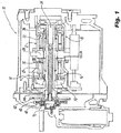
- FIG. 1 an integrated drive generator (IDG) designated generally by reference numeral 10.
- IDG 10 is designed to be coupled to the spool of a gas turbine engine through an accessory drive gearbox (not shown).
- the IDG 10 includes an input shaft that receives rotational drive from an accessory drive gearbox.
- the rotational speed of the input shaft varies depending upon the operation of the gas turbine engine.
- a hydraulic unit 12 housed within the IDG 10 cooperates with a differential assembly to convert the variable rotational speed of the input shaft to a fixed rotational output speed supplied to a generator.
- the hydraulic unit 12 of the IDG 10 has a housing 14 that supports a variable displacement hydraulic pump 16 and a fixed displacement hydraulic motor 18.
- the pump 16 and motor 18 have respective cylinder blocks 20 and 22 which are arranged for rotation about a common axis within the housing 14 on opposite sides of a stationary port plate 24.
- the port plate 24 is formed with apertures to enable hydraulic fluid communication between the pump 16 and motor 18 and maintain a hydrostatic balance between the cylinder blocks 20 and 22, during normal operation of the hydraulic unit 12.
- the operation of the hydraulic unit 12 in IDG 10 of an aircraft involves transmission of torque from a gas turbine engine of the aircraft to an input of the IDG, which rotates an input drive gear or gear shaft 50 of the hydraulic unit 12.
- the cylinder block 20 of the pump 16 is connected to the gear shaft 50 for rotation therewith.
- Pistons 32 within the cylinder block 20 of pump 16 are displaced during this rotation by an amount that is related to the position of a variable wobbler 30 of the pump 16. More particularly, the stroke of each piston 32 within cylinder block 20 depends upon the angular position of the variable wobbler 30 relative to the central axis of the hydraulic unit 12.
- Hydraulic fluid under pressure from the pump 16 is delivered to the motor 18 through the port plate 24 to rotate the cylinder block 22 and an output shaft 34 to which it is fixedly connected.
- a fixed wobbler 36 is associated with the output shaft 34 so that the operating speed of the motor 18 is a function of the displacement of the pump 16.
- the rotary output from shaft 34 which is coupled to gear shaft 48, is added to or subtracted from the rotary motion provided by the engine through the differential gearing of the IDG 10 so that the electrical generator will be operated at a substantially constant rotational speed. That is, since the rotational speed from the engine to the gear shaft 48 will vary, the position of the variable wobbler 30 is adjusted in response to the detected speed variations. This provides the necessary reduction or increase in speed, so as to obtain the desired constant output speed to the generator.
- the input gear shaft 48 is shown separated from the hydraulic unit 12 and it is part of a gear shaft assembly 40 that also includes a roller bearing assembly 70, which will be discussed in greater detail below.
- the gear shaft 48 includes a main body portion 52 having a central axis, an outer periphery 54, an inner periphery 56 and a medial region 58 that extends between the outer periphery 54 and the inner periphery 56.
- the outer periphery 54 of the main body portion 52 of the gear shaft 48 includes a plurality of circumferential gear teeth 60 for meshing with the differential assmebly.
- the gear shaft 48 further includes an elongated axial shaft portion 66 that extends distally from the main body portion 52 of the gear shaft 48.
- a distal section of the axial shaft portion 66 of the gear shaft 48 includes a plurality of circumferential gear teeth 68 for meshing with output shaft 34 of the hydraulic unit 12.
- the inner periphery 56 of the main body portion 52 of the gear shaft 48 includes an annular bearing surface 62 that circumscribes a cylindrical cavity 64 dimensioned to accommodate the roller bearing assembly 70.
- the gear shaft assembly 40 further includes roller bearing assembly 70, which is arranged within the cylindrical cavity 64 of the main body portion 52 of the gear shaft 48.
- the roller bearing assembly 70 includes a plurality of circumferentially arranged roller bearing elements 72 that are supported in a cage 75 and are in rolling contact with the annular bearing surface 62 of the cylindrical cavity 64.
- the roller bearing assembly 70 includes more than ten circumferentially arranged roller bearing elements 72. More preferably, as best seen in Fig. 3 , the roller bearing assembly 70 includes twelve circumferentially arranged roller bearing elements 72.
- the cylindrical cavity 64 of the main body portion 52 of the gear shaft 48 is dimensioned and configured to accommodate a roller bearing assembly 70 that includes twelve circumferentially arranged roller bearing elements 72.
- the annular bearing surface 62 of the main body portion 52 of the gear shaft 48 defines an outer race of the roller bearing assembly 70.
- the roller bearing assembly 70 also includes an inner race structure 74 having an end cap 76.
- the end cap 76 is configured to be fastened to the housing of the IDG 10 by a threaded fastener 78, as best seen in Fig. 1 . Consequently, during normal operation, the outer race of the roller bearing assembly 70 (i.e., annular bearing surface 62) rotates relative to the inner race structure 74 of the roller bearing assembly 70.
- the annular bearing surface 62 of the main body portion of the gear shaft 48 has an inner diameter D 1 of approximately 1.96 inches
- the cylindrical cavity 64 of the main body portion 52 of the gear shaft 48 includes a circumferential shoulder 65 extending radially inwardly from the annular bearing surface 62 for supporting the roller bearing elements 72, which his best seen in Fig. 6 .
- the shoulder 65 has an inner diameter D 2 of approximately 1.81 inches.
- annular bearing surface 62 of the main body portion 52 of the gear shaft 48 is formed by an annular wall 67 that has an outer diameter D 3 of approximately 2.22 inches, and the axial shaft portion 66 of the gear shaft 48 has an outer diameter D 4 of approximately 0.55 inches, as shown in Fig. 5 .
- the medial region 58 of the main body portion 52 of the gear shaft 48 extends from the outer diameter of the annular wall 67 to the outer periphery 54 of the main body portion 52 and a plurality of circumferentially spaced apart bore holes 80 extend through the medial region 58 to reduce the weight of the gear shaft 48.
- the medial region 58 of the main body portion 52 of the gear shaft 48 includes an odd number of circumferentially spaced apart bore holes 80 for weight reduction, and in a preferred embodiment of the gear shaft assembly 40 there are thirteen circumferentially spaced apart bore holes 80 in the medial region 58 of the main body portion 52 of the gear shaft 48.
Landscapes
- Engineering & Computer Science (AREA)
- General Engineering & Computer Science (AREA)
- Mechanical Engineering (AREA)
- Chemical & Material Sciences (AREA)
- Combustion & Propulsion (AREA)
- Ocean & Marine Engineering (AREA)
- General Details Of Gearings (AREA)
Applications Claiming Priority (1)
| Application Number | Priority Date | Filing Date | Title |
|---|---|---|---|
| US16/212,984 US20200182292A1 (en) | 2018-12-07 | 2018-12-07 | Gear shaft assembly for a hydraulic unit |
Publications (1)
| Publication Number | Publication Date |
|---|---|
| EP3663565A1 true EP3663565A1 (de) | 2020-06-10 |
Family
ID=68806696
Family Applications (1)
| Application Number | Title | Priority Date | Filing Date |
|---|---|---|---|
| EP19213871.7A Withdrawn EP3663565A1 (de) | 2018-12-07 | 2019-12-05 | Getriebewellenanordnung für eine hydraulische einheit |
Country Status (2)
| Country | Link |
|---|---|
| US (1) | US20200182292A1 (de) |
| EP (1) | EP3663565A1 (de) |
Citations (3)
| Publication number | Priority date | Publication date | Assignee | Title |
|---|---|---|---|---|
| US4965477A (en) * | 1989-03-17 | 1990-10-23 | Sundstrand Corporation | Integrated drive generator with permanent magnet generator on second shaft |
| US20150333607A1 (en) * | 2012-07-06 | 2015-11-19 | Hamilton Sundstrand Corporation | Integrated drive generator housing |
| US20160201697A1 (en) | 2015-01-14 | 2016-07-14 | Hamilton Sundstrand Corporation | Variable wobbler for hydraulic unit |
-
2018
- 2018-12-07 US US16/212,984 patent/US20200182292A1/en not_active Abandoned
-
2019
- 2019-12-05 EP EP19213871.7A patent/EP3663565A1/de not_active Withdrawn
Patent Citations (3)
| Publication number | Priority date | Publication date | Assignee | Title |
|---|---|---|---|---|
| US4965477A (en) * | 1989-03-17 | 1990-10-23 | Sundstrand Corporation | Integrated drive generator with permanent magnet generator on second shaft |
| US20150333607A1 (en) * | 2012-07-06 | 2015-11-19 | Hamilton Sundstrand Corporation | Integrated drive generator housing |
| US20160201697A1 (en) | 2015-01-14 | 2016-07-14 | Hamilton Sundstrand Corporation | Variable wobbler for hydraulic unit |
Also Published As
| Publication number | Publication date |
|---|---|
| US20200182292A1 (en) | 2020-06-11 |
Similar Documents
| Publication | Publication Date | Title |
|---|---|---|
| CA2356726C (en) | Transmission for wind generators | |
| US6026711A (en) | Harmonic drive bearing arrangement | |
| CA2874786C (en) | Speed change device | |
| EP1598268B1 (de) | Rotorwellenlagerung und Antriebsanordnung | |
| US7090465B2 (en) | Planet carrier assembly for wind turbine drive assembly | |
| EP3023616B1 (de) | Variable welle für hydraulikeinheit | |
| EP3045721A1 (de) | Variables taumelelement für hydraulikeinheit | |
| US20040213671A1 (en) | Drive assembly | |
| EP3023651B1 (de) | Festwelle für hydraulikeinheit | |
| EP3663565A1 (de) | Getriebewellenanordnung für eine hydraulische einheit | |
| WO2009048403A1 (en) | Device for changing a blade pitch of a blade in a wind turbine rotor | |
| EP3514398B1 (de) | Innerer lagerring einer festen blockwelle für einen integrierten antriebsgenerator | |
| EP3070330A1 (de) | Zylinderblockanordnung für hydraulikaggregat | |
| EP3048302B1 (de) | Gleitschuhhalter für hydraulikeinheit | |
| US11002259B2 (en) | Variable wobbler for a hydraulic unit | |
| US20160281781A1 (en) | Roller bearing outer race for hydraulic unit | |
| EP1128094A1 (de) | Lageranordnung für ein Wellgetriebe | |
| US11959541B2 (en) | Compact geared reduction unit for application with transmission shaft subjected to radial loads | |
| EP3061965B1 (de) | Wälzlageraussenring einer hydraulikeinheit | |
| EP4617518A1 (de) | Wälzlager für eine getriebeanordnung für ein flugzeug | |
| EP3514377B1 (de) | Variable wobblerplatte für integrierten antriebsgenerator | |
| EP3511595B1 (de) | Variable blockwelle für einen integrierten antriebsgenerator | |
| JP7421331B2 (ja) | ヘリコプターのトランスミッション構造 | |
| WO2004013516A1 (en) | Gear transmission unit with planet carrier | |
| EP3045720B1 (de) | Gleitschuhhalterkugel für hydraulikeinheit |
Legal Events
| Date | Code | Title | Description |
|---|---|---|---|
| PUAI | Public reference made under article 153(3) epc to a published international application that has entered the european phase |
Free format text: ORIGINAL CODE: 0009012 |
|
| STAA | Information on the status of an ep patent application or granted ep patent |
Free format text: STATUS: THE APPLICATION HAS BEEN PUBLISHED |
|
| AK | Designated contracting states |
Kind code of ref document: A1 Designated state(s): AL AT BE BG CH CY CZ DE DK EE ES FI FR GB GR HR HU IE IS IT LI LT LU LV MC MK MT NL NO PL PT RO RS SE SI SK SM TR |
|
| AX | Request for extension of the european patent |
Extension state: BA ME |
|
| STAA | Information on the status of an ep patent application or granted ep patent |
Free format text: STATUS: REQUEST FOR EXAMINATION WAS MADE |
|
| 17P | Request for examination filed |
Effective date: 20201210 |
|
| RBV | Designated contracting states (corrected) |
Designated state(s): AL AT BE BG CH CY CZ DE DK EE ES FI FR GB GR HR HU IE IS IT LI LT LU LV MC MK MT NL NO PL PT RO RS SE SI SK SM TR |
|
| STAA | Information on the status of an ep patent application or granted ep patent |
Free format text: STATUS: EXAMINATION IS IN PROGRESS |
|
| 17Q | First examination report despatched |
Effective date: 20210803 |
|
| STAA | Information on the status of an ep patent application or granted ep patent |
Free format text: STATUS: THE APPLICATION HAS BEEN WITHDRAWN |
|
| 18W | Application withdrawn |
Effective date: 20220103 |