EP3025817B1 - Outil de coupe pour dressage d'embouts - Google Patents
Outil de coupe pour dressage d'embouts Download PDFInfo
- Publication number
- EP3025817B1 EP3025817B1 EP14838906.7A EP14838906A EP3025817B1 EP 3025817 B1 EP3025817 B1 EP 3025817B1 EP 14838906 A EP14838906 A EP 14838906A EP 3025817 B1 EP3025817 B1 EP 3025817B1
- Authority
- EP
- European Patent Office
- Prior art keywords
- cutting plate
- breaker
- hole
- cutting
- screw
- Prior art date
- Legal status (The legal status is an assumption and is not a legal conclusion. Google has not performed a legal analysis and makes no representation as to the accuracy of the status listed.)
- Active
Links
Images
Classifications
-
- B—PERFORMING OPERATIONS; TRANSPORTING
- B23—MACHINE TOOLS; METAL-WORKING NOT OTHERWISE PROVIDED FOR
- B23K—SOLDERING OR UNSOLDERING; WELDING; CLADDING OR PLATING BY SOLDERING OR WELDING; CUTTING BY APPLYING HEAT LOCALLY, e.g. FLAME CUTTING; WORKING BY LASER BEAM
- B23K11/00—Resistance welding; Severing by resistance heating
- B23K11/30—Features relating to electrodes
- B23K11/3063—Electrode maintenance, e.g. cleaning, grinding
-
- B—PERFORMING OPERATIONS; TRANSPORTING
- B23—MACHINE TOOLS; METAL-WORKING NOT OTHERWISE PROVIDED FOR
- B23B—TURNING; BORING
- B23B27/00—Tools for turning or boring machines; Tools of a similar kind in general; Accessories therefor
- B23B27/14—Cutting tools of which the bits or tips or cutting inserts are of special material
- B23B27/16—Cutting tools of which the bits or tips or cutting inserts are of special material with exchangeable cutting bits or cutting inserts, e.g. able to be clamped
- B23B27/1625—Cutting tools of which the bits or tips or cutting inserts are of special material with exchangeable cutting bits or cutting inserts, e.g. able to be clamped with plate-like cutting inserts of special shape clamped by a clamping member acting almost perpendicularly on the chip-forming plane
- B23B27/1629—Cutting tools of which the bits or tips or cutting inserts are of special material with exchangeable cutting bits or cutting inserts, e.g. able to be clamped with plate-like cutting inserts of special shape clamped by a clamping member acting almost perpendicularly on the chip-forming plane in which the clamping member breaks the chips
-
- B—PERFORMING OPERATIONS; TRANSPORTING
- B23—MACHINE TOOLS; METAL-WORKING NOT OTHERWISE PROVIDED FOR
- B23B—TURNING; BORING
- B23B5/00—Turning-machines or devices specially adapted for particular work; Accessories specially adapted therefor
- B23B5/16—Turning-machines or devices specially adapted for particular work; Accessories specially adapted therefor for bevelling, chamfering, or deburring the ends of bars or tubes
- B23B5/166—Devices for working electrodes
-
- B—PERFORMING OPERATIONS; TRANSPORTING
- B23—MACHINE TOOLS; METAL-WORKING NOT OTHERWISE PROVIDED FOR
- B23B—TURNING; BORING
- B23B2270/00—Details of turning, boring or drilling machines, processes or tools not otherwise provided for
- B23B2270/30—Chip guiding or removal
Definitions
- the present invention relates to tip dressing cutters for cutting distal ends of electrode tips for spot welding according to the preamble of claim 1.
- a distal end of an electrode tip used for spot welding wears due to welding performed a predetermined number of times, or the condition of the distal end deteriorates due to an oxide film, etc. sticking onto the distal end. Therefore, the distal end has to be periodically cut by using a tip dresser.
- Swarf which is produced at the time of cutting the distal end of the electrode tip by a cutting blade of the tip dresser may come into contact with the distal end of the electrode tip and scratch the distal end, or may twine around the tip dresser. Therefore, directly after a piece of swarf is produced by cutting the distal end by a component called a breaker, the piece of swarf is bent and curled (or fractured).
- WO 2013/061710 A1 describes a tip dressing cutter of this kind including a holder which has a rotation axis extending in a vertical direction and has a substantially C shape when viewed in plan.
- the holder has a cutout recess formed therein.
- the cutout recess opens laterally outward and extends in the vertical direction to open both upward and downward.
- Part of the inner side surface of the cutout recess is formed as a mounting surface.
- the mounting surface extends along the longitudinal direction of the holder.
- the holder has a pair of curved surfaces as upper and lower surfaces. Each curved surface has a diameter gradually decreasing with decreasing distance to a center section of the holder.
- each curved surface corresponds to the shape of a distal end of an associated one of electrode tips when the center axes of the electrode tips coincide with the rotation axis of the holder.
- a cutting plate can be attached to the mounting surface.
- the cutting plate has a pair of cutting blades each corresponding to the shape of an associated one of the curved surfaces.
- the cutting plate and the breaker are fastened together to the mounting surface by a screw.
- the holder is turned with the distal ends of the electrode tips each being received by a corresponding one of the curved surfaces, thereby cutting the distal ends of the electrode tips by the cutting blades of the cutting plate, while pieces of swarf produced by cutting the distal ends by the cutting blades are bent by the breaker.
- the known breaker has a recessed surface facing the cutting plate and having a diameter decreasing with increasing distance from an outer periphery of the recessed surface facing the cutting plate in a direction opposite to the cutting plate, and a through hole through which a screw is insertable into the through hole and which opens to the recessed surface. Additionally, said breaker is configured to be attached to the cutting plate with the recessed surface being in close contact with the plane of the cutting plate, by screwing the screw inserted through the through hole into the rotator.
- a surface of the cutting plate and a surface of the breaker which face each other may be precisely finished, but this increases machining costs.
- the present invention is characterized by devising the shape of a breaker.
- the present invention is directed to a tip dressing cutter including: a rotator having a tip receiving portion configured to receive a distal end of an electrode tip for spot welding; a cutting plate configured to cut the distal end of the electrode tip when the rotator is turned with the cutting plate being attached to the rotator and with the distal end of the electrode tip being received by the tip receiving portion; and a breaker attached to a plane of the cutting plate and guiding a piece of swarf ejected by cutting the electrode tip by the cutting plate so that the piece of swarf is bent in a predetermined direction.
- the present invention has provided the tip dressing cutter with the following features.
- the breaker has a recessed surface facing the cutting plate and having a diameter gradually decreasing with increasing distance from an outer periphery of the recessed surface facing the cutting plate in a direction opposite to the cutting plate, and a through hole through which a screw is insertable and which opens to the recessed surface.
- the breaker is configured to be attached to the cutting plate with the recessed surface being in close contact with the plane of the cutting plate, by screwing the screw inserted through the through hole into at least one of the rotator or the cutting plate.
- the breaker of the first aspect of the invention has a ring shape at a center position of which the through hole is formed.
- the breaker has an outer peripheral portion provided with an inclined plane having a diameter gradually decreasing with increasing distance from the cutting plate.
- a countersunk hole is formed around the through hole in a surface of the breaker opposite to the cutting plate of the third aspect of the invention, the screw has a head surface having a diameter gradually decreasing in a direction opposite to a fastening direction, and the countersunk hole has a depth which allows the inclined plane to be flush with the head surface of the screw when the breaker is attached to the cutting plate.
- the recessed surface of the breaker forms a space between a portion of the breaker around the through hole and the cutting plate. Therefore, when a screw is inserted through the through hole and the breaker is fastened to the cutting plate or the rotator by the screw, the portion of the breaker around the through hole warps toward the cutting plate due to the fastening force of the screw. At this time, a reaction of the warp of the portion around the through hole toward the cutting plate generates force toward the cutting plate at the outer periphery of the breaker.
- the distance from the through hole to the outer periphery of the breaker is uniform. Therefore, when the portion of the breaker around the through hole warps toward the cutting plate due to the fastening force of the screw, force from the outer periphery of the breaker toward the cutting plate is uniform in the periphery of the breaker. Thus, formation of a gap between the cutting plate and the outer periphery of the breaker due to nonuniform force from the outer periphery of the breaker to the cutting plate can be prevented.
- a piece of swarf produced by cutting the distal end by the cutting blade is gently bent due to the inclination of the inclined plane. Therefore, a bend in the piece of swarf at an acute angle which causes the piece of swarf to be in contact with the distal end of the electrode tip after the cutting is prevented, so that a cut area of the electrode tip can be kept clean.
- no step is formed between the inclined plane and the head of the screw. Therefore, after the piece of swarf produced by cutting the distal end by the cutting blade is guided to the inclined plane, the piece of swarf smoothly goes over the head of the screw. This can ensure avoidance of contact of the piece of swarf with the cut distal end of the electrode tip caused by a change in moving direction of the piece of swarf toward the electrode tip due to the head of the screw.
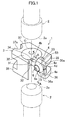
- FIGS. 1 and 2 show a cutter 1 according to the present invention.
- the cutter 1 is attached to a tip dresser described in, for example, aforementioned WO 2013/061710 A1 , in order to cut distal ends 2a of electrode tips 2 for spot welding.
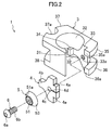
- the cutter 1 is wide and substantially C-shaped when viewed in plan and includes a metal holder 3 (rotator) having a vertically short columnar shape.
- the holder 3 is turned around a rotation axis C extending in the vertical direction at a center position of the holder 3 by rotation of a drive motor (not shown).
- a cutout recess 31 is formed in one longitudinal portion of the holder 3.
- the cutout recess 31 is opens laterally outward and extends in the vertical direction to open both upward and downward.
- the cutout recess 31 is a substantially fan-shaped cutout when viewed in plan.
- the holder 3 has a pair of curved surfaces 32 (tip receiving portions) as upper and lower surfaces. Each curved surface 32 has a diameter decreasing with decreasing distance to the center position of the holder 3.
- each curved surface 32 corresponds to the shape of an associated one of the distal ends 2a of the electrode tips 2 when the center axes of the electrode tips 2 coincide with the rotation axis C of the holder 3, so that each curved surface 32 can receive the associated one of the distal ends 2a.
- part of an inner side surface of the cutout recess 31 is formed as a mounting surface 33.
- the mounting surface 33 extends along the longitudinal direction of the holder 3.
- the mounting surface 33 has a substantially triangular shape in side view.
- a fastening hole 33a is formed at the center of the mounting surface 33.
- An inner circumferential surface of the fastening hole 33a has a female thread.
- a first positioning projection 34 having a block shape protrudes from a side of the mounting surface 33 facing the rotation axis C.
- An upper extending portion 35 and a lower extending portion 36 which extend laterally outward are respectively provided at an upper edge and a lower edge of the one longitudinal portion of the holder 3.
- a portion of the upper extending portion 35 facing the mounting surface 33 protrudes beyond the mounting surface 33, and the protruding portion is a second positioning projection 35a.
- a portion of the lower extending portion 36 facing the mounting surface 33 also protrudes beyond the mounting surface 33 to correspond to the second positioning projection 35a, and the protruding portion is a third positioning projection 36a.
- an upper protruding portion 37 and a lower protruding portion 38 are respectively provided at an upper edge and a lower edge of the other longitudinal portion of the holder 3.
- the upper protruding portion 37 and the lower protruding portion 38 protrude laterally outward and extend in a horizontal direction crossing the longitudinal direction of the holder 3.
- a semicircular recess 37a which opens laterally outward is formed at a midway position of the upper protruding portion 37.
- a substantially triangular metal cutting plate 4 for cutting the distal ends 2a of the electrode tips 2 can be attached to the mounting surface 33 with the thickness direction of the cutting plate 4 oriented in the horizontal direction.
- Positioning recesses 4a and 4e each of which is a rectangular cutout in side view are respectively formed at an upper portion and a lower portion of one longitudinal portion of the cutting plate 4.
- cutting blades 4b are provided at an upper edge and a lower edge of the other longitudinal portion of the cutting plate 4.
- Each cutting blade 4b has a curved shape corresponding to an associated one of the curved surfaces 32 when the cutting plate 4 is attached to the mounting surface 33.
- a mounting hole 4c is formed at the center of the cutting plate 4 to pass through the cutting plate 4.
- a slit 4d is formed in the one longitudinal portion of the cutting plate 4. The slit 4d extends from the mounting hole 4c in the horizontal direction and is open at one longitudinal edge of the cutting plate 4.
- the other longitudinal edge of the cutting plate 4 is placed on the first positioning projection 34, the second positioning projection 35a is fitted into the positioning recess 4a, and the third positioning projection 36a is fitted into the positioning recess 4e.
- the cutting plate 4 is positioned with respect to the mounting surface 33, so that the mounting hole 4c corresponds to the fastening hole 33a.
- a ring-shaped metal breaker 5 having a through hole 51 formed at a center position thereof is attached to a plane of the cutting plate 4 opposite to the mounting surface 33.
- an outer peripheral portion of the breaker 5 has an acute shape in which the thickness of the outer peripheral portion decreases with decreasing distance to an outer periphery of the breaker.
- a surface of the breaker 5 facing the cutting plate 4 corresponds to a recessed surface 52 having a diameter gradually decreasing with increasing distance from an outer periphery of the surface of the breaker 5 facing the cutting plate 4 in a direction opposite to the cutting plate 4.
- the through hole 51 is open to the recessed surface 52.
- a countersunk hole 51a is formed around the through hole 51.
- An inclined plane 53 having a diameter gradually decreasing with increasing distance from the cutting plate 4 is provided at the outer peripheral portion of the breaker 5.
- the cutting plate 4 and the breaker 5 can be attached to the mounting surface 33 by a screw 6.
- the screw 6 is a torx (registered trademark) screw including a head 6a and a shaft 6b whose outer circumferential surface has a male thread.
- a surface of the head 6a has a gently curved shape having a diameter gradually decreasing in a direction opposite to a fastening direction.
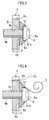
- the cutting plate 4 is placed on the mounting surface 33 of the holder 3, the breaker 5 is placed on the plane of the cutting plate 4, and the shaft 6b of the screw 6 is inserted through the through hole 51 of the breaker 5 and the mounting hole 4c of the cutting plate 4 sequentially.
- the shaft 6b is screwed into the fastening hole 33a of the holder 3, so that a portion of the breaker 5 around the through hole 51 warps toward the cutting plate 4, and the recessed surface 52 is in close contact with the plane of the cutting plate 4.
- the cutting plate 4 and the breaker 5 are together screwed onto the mounting surface 33.
- the countersunk hole 51a has a depth which allows the inclined plane 53 to be flush with the surface of the head 6a of the screw 6 when the breaker 5 is attached to the cutting plate 4.
- the holder 3 is turned around the rotation axis C with the cutting plate 4 and the breaker 5 being attached to the holder 3 and with the distal ends 2a of the electrode tips 2 being received by the curved surfaces 32, thereby cutting the distal ends 2a of the electrode tips 2 by the cutting blades 4b of the cutting plate 4.
- the breaker 5 guides a piece of swarf 7 ejected by cutting the distal end 2a of the electrode tip 2 by the cutting plate 4 so that the piece of swarf 7 is bent in a predetermined direction.
- the cutting plate 4 is caused to correspond to the mounting surface 33 so that both of the cutting blades 4b of the cutting plate 4 face the rotation axis C of the holder 3.
- the other longitudinal edge of the cutting plate 4 is placed on the first positioning projection 34, and the cutting plate 4 is moved toward the mounting surface 33.
- the second positioning projection 35a fits into the positioning recess 4a
- the third positioning projection 36a fits into the positioning recess 4e, so that the cutting plate 4 is positioned with respect to the mounting surface 33.
- the breaker 5 is placed on the cutting plate 4 such that the recessed surface 52 faces the plane of the cutting plate 4 opposite to the mounting surface 33 and the through hole 51 corresponds to the mounting hole 4c (the breaker 5 is set at an attachment position on the cutting plate 4).
- the recessed surface 52 of the breaker 5 forms a space S between the portion of the breaker 5 around the through hole 51 and the cutting plate 4.
- the shaft 6b of the screw 6 is inserted through the through hole 51 of the breaker 5 and the mounting hole 4c of the cutting plate 4 sequentially, and is screwed into the fastening hole 33a of the holder 3.
- the portion of the breaker 5 around the through hole 51 is pressed by the head 6a due to the fastening force of the screw 6, and warps toward the cutting plate 4.
- the space S disappears, so that the cutting plate 4 and the breaker 5 are in close contact with each other.
- a reaction of the warp of the portion around the through hole 51 toward the cutting plate 4 generates force toward the cutting plate 4 at the outer periphery of the breaker 5, and the outer periphery of the breaker 5 is pressed onto the cutting plate 4, so that a gap between the outer periphery of the breaker 5 and the cutting plate 4 disappears.
- the cutting plate 4 and the breaker 5 are together fastened to the mounting surface 33 of the holder 3. Therefore, the swarf 7 is no longer caught between the cutting plate 4 and the breaker 5, so that the functioning of the breaker 5 can be ensured.
- the breaker 5 Since the breaker 5 has a ring shape at the center position of which the through hole 51 is formed, the distance from the through hole 51 to the outer periphery of the breaker 5 is uniform. Thus, when the portion of the breaker 5 around the through hole 51 warps toward the cutting plate 4 due to the fastening force of the screw 6, force from the outer periphery of the breaker 5 toward the cutting plate 4 is uniform around the breaker 5. Thus, formation of the gap between the cutting plate 4 and the outer periphery of the breaker 5 due to nonuniform force from the outer periphery of the breaker 5 toward the cutting plate 4 can be prevented.
- a drive motor (not shown) of a tip dresser is rotated to turn the cutter 1 mounted to the tip dresser about the rotation axis C.
- one of the electrode tips 2 is moved above the cutter 1, and the other of the electrode tips 2 is moved under the cutter 1. At the same time, the center axes of the electrode tips 2 are allowed to coincide with the rotation axis C of the cutter 1.
- each electrode tip 2 is brought close to a corresponding one of the curved surfaces 32 of the holder 3 along the rotation axis C.
- each curved surface 32 receives a corresponding one of the distal ends 2a of the electrode tips 2, and each cutting blade 4b of the cutting plate 4 comes into contact with a corresponding one of the distal ends 2a of the electrode tips 2, thereby cutting the distal end 2a.
- a piece of swarf 7 obtained by cutting each distal end 2a by a corresponding one of the cutting blades 4b is gently bent due to the inclination of the inclined plane 53. This prevents the piece of swarf 7 from being bent at an acute angle by the breaker 5.
- the piece of swarf 7 does not come into contact with the distal end 2a of the electrode tip 2 after the cutting. Therefore, the cut area of the electrode tip 2 can be kept clean.
- the countersunk hole 51a eliminates a step between the inclined plane 53 and the head 6a of the screw 6. Therefore, after the piece of swarf 7 obtained by cutting the distal end 2a by the cutting blade 4b is guided to the inclined plane 53, the piece of swarf 7 smoothly goes over the head 6a of the screw 6. This can ensure avoidance of contact of the piece of swarf 7 with the distal end 2a of the electrode tip 2 caused by a change in moving direction of the piece of swarf 7 by the head 6a of the screw 6.
- the breaker 5 is made of metal in the embodiment of the present invention, the breaker 5 may be made of a resin.
- the screw 6 is a torx screw, but any types of screws can be used as long as they can fasten the cutting plate 4 and the breaker 5 together to the mounting surface 33 of the holder 3.
- the shaft 6b of the screw 6 is screwed into the fastening hole 33a of the holder 3, thereby fastening the breaker 5 to the cutting plate 4.
- the shaft 6b of the screw 6 may be screwed to the cutting plate 4 to attach the breaker 5 to the cutting plate 4.
- the shaft 6b of the screw 6 may be screwed at least to the holder 3 or the cutting plate 4 to attach the breaker 5 to the cutting plate 4.
- the present invention is suitable for tip dressing cutters used to cut distal ends of electrode tips for spot welding.
Landscapes
- Engineering & Computer Science (AREA)
- Mechanical Engineering (AREA)
- Finish Polishing, Edge Sharpening, And Grinding By Specific Grinding Devices (AREA)
- Turning (AREA)
- Apparatuses And Processes For Manufacturing Resistors (AREA)
- Scissors And Nippers (AREA)
- Harvester Elements (AREA)
- Removal Of Insulation Or Armoring From Wires Or Cables (AREA)
Claims (2)
- Outil de coupe pour dressage d'embouts (1) comprenant :un rotateur (3) ayant une partie réceptrice d'embout (32) configurée pour recevoir une extrémité distale d'un embout d'électrode (2) pour un soudage par points ;une plaque de coupe (4) configurée pour couper l'extrémité distale de l'embout d'électrode (2) lorsque le rotateur (3) est tourné avec la plaque de coupe (4) fixée au rotateur (3) et avec l'extrémité distale de l'embout d'électrode (2) reçue par la partie réceptrice d'embout (32) ; etun élément de rupture (5) fixé à un plan de la plaque de coupe (4) et le guidage d'une pièce de déchet (7) éjectée en coupant l'embout d'électrode (2) par la plaque de coupe (4) de sorte que la pièce de déchet (7) soit courbée dans une direction prédéterminée,dans lequel l'élément de rupture (5) a une partie périphérique externe pourvue d'un plan incliné (53) ayant un diamètre qui diminue graduellement à mesure que la distance depuis la plaque de coupe (4) augmente,caractérisé en ce quel'élément de rupture (5) aune surface évidée (52) faisant face à la plaque de coupe (4) et ayant un diamètre qui diminue à mesure que la distance depuis la périphérie externe de la surface évidée (52) faisant face à la plaque de coupe (4) dans une direction opposée à la plaque de coupe (4) augmente, etun trou traversant (51) à travers lequel une vis (6) peut être insérée dans le trou traversant (51) et qui s'ouvre sur la surface évidée (52), etl'élément de rupture (5) est configuré pour être fixé à la plaque de coupe (4) avec la surface évidée (52) en contact étroit avec le plan de la plaque de coupe (4) en vissant la vis (6) insérée à travers le trou traversant (51) dans au moins l'un du rotateur (3) ou de la plaque de coupe (4),un trou chanfreiné (51a) est formé autour du trou traversant (51) dans une surface de l'élément de rupture (5) opposée à la plaque de coupe (4),la vis (6) a une surface de tête ayant un diamètre qui diminue graduellement dans une direction opposée à une direction de fixation, etle trou chanfreiné (51a) a une profondeur qui permet au plan incliné (53) d'être de niveau avec la surface de tête de la vis (6) lorsque l'élément de rupture (5) est fixé à la plaque de coupe (4).
- Outil de coupe pour dressage d'embouts (1) selon la revendication 1, dans lequel l'élément de rupture (5) a une forme annulaire dans la position centrale de laquelle le trou traversant (51) est formé.
Applications Claiming Priority (1)
| Application Number | Priority Date | Filing Date | Title |
|---|---|---|---|
| PCT/JP2014/005006 WO2016051432A1 (fr) | 2014-09-30 | 2014-09-30 | Outil de coupe pour dressage d'embouts |
Publications (3)
| Publication Number | Publication Date |
|---|---|
| EP3025817A4 EP3025817A4 (fr) | 2016-06-01 |
| EP3025817A1 EP3025817A1 (fr) | 2016-06-01 |
| EP3025817B1 true EP3025817B1 (fr) | 2016-11-09 |
Family
ID=55583487
Family Applications (1)
| Application Number | Title | Priority Date | Filing Date |
|---|---|---|---|
| EP14838906.7A Active EP3025817B1 (fr) | 2014-09-30 | 2014-09-30 | Outil de coupe pour dressage d'embouts |
Country Status (7)
| Country | Link |
|---|---|
| US (1) | US9770779B2 (fr) |
| EP (1) | EP3025817B1 (fr) |
| JP (1) | JP5951137B1 (fr) |
| KR (1) | KR101731197B1 (fr) |
| CN (1) | CN105658369B (fr) |
| BR (1) | BR112015004090B1 (fr) |
| WO (1) | WO2016051432A1 (fr) |
Families Citing this family (6)
| Publication number | Priority date | Publication date | Assignee | Title |
|---|---|---|---|---|
| US10213867B2 (en) * | 2017-02-23 | 2019-02-26 | Semtorq, Inc. | Tip dresser blade |
| US10335893B2 (en) * | 2017-02-23 | 2019-07-02 | Semtorq, Inc. | Tip dresser blade |
| CN107493967B (zh) * | 2017-08-30 | 2020-05-05 | 宁波佗鹊堂生物科技有限公司 | 蛹虫草分离装置 |
| JP6963814B2 (ja) | 2018-04-16 | 2021-11-10 | 株式会社キョクトー | チップドレス用切削カッター |
| DE112020002951T5 (de) * | 2019-06-18 | 2022-03-17 | Magna International Inc. | Spitzenbearbeitungsinstallationssystem und Verfahren |
| JP7333605B2 (ja) * | 2019-11-18 | 2023-08-25 | 株式会社キョクトー | チップドレッサー |
Family Cites Families (18)
| Publication number | Priority date | Publication date | Assignee | Title |
|---|---|---|---|---|
| JPS53150828U (fr) * | 1977-05-02 | 1978-11-28 | ||
| US4954687A (en) * | 1988-10-20 | 1990-09-04 | Contacts, Metals And Welding, Inc. | Resistance welding electrode and process |
| JP2673787B2 (ja) * | 1994-11-22 | 1997-11-05 | 本田技研工業株式会社 | チップドレッサー |
| IT1303739B1 (it) * | 1998-11-11 | 2001-02-23 | Fata Automation | Dispositivo riformatore per elettrodi di saldatura |
| SE529065C2 (sv) * | 2004-10-20 | 2007-04-24 | Seco Tools Ab | Skärverktyg där skäret har en spånkanal som skär släppningsytan |
| JP2007038256A (ja) * | 2005-08-02 | 2007-02-15 | Honda Motor Co Ltd | チップドレッサ |
| US8436269B2 (en) * | 2006-09-28 | 2013-05-07 | GM Global Technology Operations LLC | Welding electrode with contoured face |
| US7510352B2 (en) * | 2007-08-03 | 2009-03-31 | Kennametal Inc. | Integral cutting insert clamping mechanism |
| DE102008006703A1 (de) * | 2008-01-30 | 2009-08-06 | Cnc Precision S.R.O. | Schneide für die Bearbeitung von Punktschweißelektroden, Fräswerkzeug und Kappenfräser |
| US8388283B2 (en) * | 2008-12-08 | 2013-03-05 | GM Global Technology Operations LLC | Chip catcher for weld tip dresser |
| KR101047019B1 (ko) * | 2009-06-30 | 2011-07-06 | 박희만 | 절삭량 조절이 가능한 스폿 용접 팁 드레서용 홀더 |
| US8274010B2 (en) * | 2010-04-28 | 2012-09-25 | GM Global Technology Operations LLC | Welding electrode with contoured face |
| WO2013061710A1 (fr) * | 2011-10-26 | 2013-05-02 | 株式会社キョクトー | Dresseur de pointe |
| US8920218B2 (en) * | 2012-07-11 | 2014-12-30 | Ford Global Technologies, Llc | Resistance spot weld electrode dresser |
| JP6139192B2 (ja) | 2013-03-14 | 2017-05-31 | 株式会社ナ・デックス | 電極チップドレッサ用の研磨刃具 |
| US9517527B2 (en) * | 2014-04-03 | 2016-12-13 | Ford Global Technologies, Llc | Method of dressing a resistance spot welding tip |
| CN203796470U (zh) * | 2014-04-25 | 2014-08-27 | 安徽江淮汽车股份有限公司 | 一种喷油器的压紧结构 |
| EP3093094B1 (fr) * | 2015-03-23 | 2017-08-02 | Kyokutoh Co., Ltd. | Dresseur de pointe |
-
2014
- 2014-09-30 JP JP2015531190A patent/JP5951137B1/ja active Active
- 2014-09-30 CN CN201480002975.6A patent/CN105658369B/zh active Active
- 2014-09-30 EP EP14838906.7A patent/EP3025817B1/fr active Active
- 2014-09-30 KR KR1020157010218A patent/KR101731197B1/ko active Active
- 2014-09-30 WO PCT/JP2014/005006 patent/WO2016051432A1/fr not_active Ceased
- 2014-09-30 BR BR112015004090-0A patent/BR112015004090B1/pt active IP Right Grant
-
2015
- 2015-05-11 US US14/708,416 patent/US9770779B2/en active Active
Also Published As
| Publication number | Publication date |
|---|---|
| KR101731197B1 (ko) | 2017-04-27 |
| EP3025817A4 (fr) | 2016-06-01 |
| US9770779B2 (en) | 2017-09-26 |
| BR112015004090B1 (pt) | 2020-12-29 |
| BR112015004090A2 (pt) | 2017-07-04 |
| US20160089747A1 (en) | 2016-03-31 |
| WO2016051432A1 (fr) | 2016-04-07 |
| CN105658369A (zh) | 2016-06-08 |
| JPWO2016051432A1 (ja) | 2017-04-27 |
| KR20160048705A (ko) | 2016-05-04 |
| EP3025817A1 (fr) | 2016-06-01 |
| CN105658369B (zh) | 2018-03-30 |
| JP5951137B1 (ja) | 2016-07-13 |
Similar Documents
| Publication | Publication Date | Title |
|---|---|---|
| EP3025817B1 (fr) | Outil de coupe pour dressage d'embouts | |
| US10717149B2 (en) | Cutting cutter for tip dressing, and tip dresser | |
| US8899888B2 (en) | Tip dresser | |
| EP2832482B1 (fr) | Outil d'usinage de type à tête interchangeable | |
| KR102471083B1 (ko) | 팁 드레싱용 절삭 커터 | |
| US8943933B2 (en) | Cutting edge replacement type groove forming tool and end face groove forming method | |
| US20190143418A1 (en) | Rotary Cutter for Cutting Damaged Threads of a Bolt | |
| US10814401B2 (en) | Vibration cutting insert | |
| KR20150143811A (ko) | 절삭날 위치의 조정 기구 및 날끝 교환식 절삭 공구 | |
| JP6164389B1 (ja) | 刃先交換式切削工具 | |
| CN107073605B (zh) | 刀具主体、刀片支承机构以及切削刀具 | |
| WO2016116964A1 (fr) | Outil de coupe d'usinage pour habillage de pointe | |
| JP2008290214A (ja) | 中ぐり加工用チップおよびこれを用いた中ぐり工具 | |
| CN205309353U (zh) | 设置有八边型凸台的压板 | |
| CN203265665U (zh) | 一种外圆切槽刀 | |
| KR101485954B1 (ko) | 나사 지지면을 가진 드라이버 | |
| WO2006016484A1 (fr) | Broyeur de copeaux et decoupeuse annulaire |
Legal Events
| Date | Code | Title | Description |
|---|---|---|---|
| PUAI | Public reference made under article 153(3) epc to a published international application that has entered the european phase |
Free format text: ORIGINAL CODE: 0009012 |
|
| 17P | Request for examination filed |
Effective date: 20150305 |
|
| A4 | Supplementary search report drawn up and despatched |
Effective date: 20151117 |
|
| AK | Designated contracting states |
Kind code of ref document: A1 Designated state(s): AL AT BE BG CH CY CZ DE DK EE ES FI FR GB GR HR HU IE IS IT LI LT LU LV MC MK MT NL NO PL PT RO RS SE SI SK SM TR |
|
| AX | Request for extension of the european patent |
Extension state: BA ME |
|
| GRAP | Despatch of communication of intention to grant a patent |
Free format text: ORIGINAL CODE: EPIDOSNIGR1 |
|
| RIC1 | Information provided on ipc code assigned before grant |
Ipc: B23B 27/00 20060101ALI20160523BHEP Ipc: B23B 27/16 20060101ALI20160523BHEP Ipc: B23B 5/16 20060101ALI20160523BHEP Ipc: B23K 11/30 20060101AFI20160523BHEP Ipc: B23B 25/00 20060101ALI20160523BHEP |
|
| INTG | Intention to grant announced |
Effective date: 20160617 |
|
| GRAS | Grant fee paid |
Free format text: ORIGINAL CODE: EPIDOSNIGR3 |
|
| GRAA | (expected) grant |
Free format text: ORIGINAL CODE: 0009210 |
|
| AK | Designated contracting states |
Kind code of ref document: B1 Designated state(s): AL AT BE BG CH CY CZ DE DK EE ES FI FR GB GR HR HU IE IS IT LI LT LU LV MC MK MT NL NO PL PT RO RS SE SI SK SM TR |
|
| DAX | Request for extension of the european patent (deleted) | ||
| REG | Reference to a national code |
Ref country code: GB Ref legal event code: FG4D |
|
| REG | Reference to a national code |
Ref country code: AT Ref legal event code: REF Ref document number: 843430 Country of ref document: AT Kind code of ref document: T Effective date: 20161115 Ref country code: CH Ref legal event code: EP |
|
| REG | Reference to a national code |
Ref country code: IE Ref legal event code: FG4D |
|
| REG | Reference to a national code |
Ref country code: DE Ref legal event code: R096 Ref document number: 602014004785 Country of ref document: DE |
|
| PG25 | Lapsed in a contracting state [announced via postgrant information from national office to epo] |
Ref country code: LV Free format text: LAPSE BECAUSE OF FAILURE TO SUBMIT A TRANSLATION OF THE DESCRIPTION OR TO PAY THE FEE WITHIN THE PRESCRIBED TIME-LIMIT Effective date: 20161109 |
|
| REG | Reference to a national code |
Ref country code: LT Ref legal event code: MG4D |
|
| REG | Reference to a national code |
Ref country code: NL Ref legal event code: MP Effective date: 20161109 |
|
| REG | Reference to a national code |
Ref country code: AT Ref legal event code: MK05 Ref document number: 843430 Country of ref document: AT Kind code of ref document: T Effective date: 20161109 |
|
| PG25 | Lapsed in a contracting state [announced via postgrant information from national office to epo] |
Ref country code: NL Free format text: LAPSE BECAUSE OF FAILURE TO SUBMIT A TRANSLATION OF THE DESCRIPTION OR TO PAY THE FEE WITHIN THE PRESCRIBED TIME-LIMIT Effective date: 20161109 Ref country code: SE Free format text: LAPSE BECAUSE OF FAILURE TO SUBMIT A TRANSLATION OF THE DESCRIPTION OR TO PAY THE FEE WITHIN THE PRESCRIBED TIME-LIMIT Effective date: 20161109 Ref country code: LT Free format text: LAPSE BECAUSE OF FAILURE TO SUBMIT A TRANSLATION OF THE DESCRIPTION OR TO PAY THE FEE WITHIN THE PRESCRIBED TIME-LIMIT Effective date: 20161109 Ref country code: NO Free format text: LAPSE BECAUSE OF FAILURE TO SUBMIT A TRANSLATION OF THE DESCRIPTION OR TO PAY THE FEE WITHIN THE PRESCRIBED TIME-LIMIT Effective date: 20170209 Ref country code: GR Free format text: LAPSE BECAUSE OF FAILURE TO SUBMIT A TRANSLATION OF THE DESCRIPTION OR TO PAY THE FEE WITHIN THE PRESCRIBED TIME-LIMIT Effective date: 20170210 |
|
| PG25 | Lapsed in a contracting state [announced via postgrant information from national office to epo] |
Ref country code: FI Free format text: LAPSE BECAUSE OF FAILURE TO SUBMIT A TRANSLATION OF THE DESCRIPTION OR TO PAY THE FEE WITHIN THE PRESCRIBED TIME-LIMIT Effective date: 20161109 Ref country code: RS Free format text: LAPSE BECAUSE OF FAILURE TO SUBMIT A TRANSLATION OF THE DESCRIPTION OR TO PAY THE FEE WITHIN THE PRESCRIBED TIME-LIMIT Effective date: 20161109 Ref country code: ES Free format text: LAPSE BECAUSE OF FAILURE TO SUBMIT A TRANSLATION OF THE DESCRIPTION OR TO PAY THE FEE WITHIN THE PRESCRIBED TIME-LIMIT Effective date: 20161109 Ref country code: HR Free format text: LAPSE BECAUSE OF FAILURE TO SUBMIT A TRANSLATION OF THE DESCRIPTION OR TO PAY THE FEE WITHIN THE PRESCRIBED TIME-LIMIT Effective date: 20161109 Ref country code: PL Free format text: LAPSE BECAUSE OF FAILURE TO SUBMIT A TRANSLATION OF THE DESCRIPTION OR TO PAY THE FEE WITHIN THE PRESCRIBED TIME-LIMIT Effective date: 20161109 Ref country code: IS Free format text: LAPSE BECAUSE OF FAILURE TO SUBMIT A TRANSLATION OF THE DESCRIPTION OR TO PAY THE FEE WITHIN THE PRESCRIBED TIME-LIMIT Effective date: 20170309 Ref country code: AT Free format text: LAPSE BECAUSE OF FAILURE TO SUBMIT A TRANSLATION OF THE DESCRIPTION OR TO PAY THE FEE WITHIN THE PRESCRIBED TIME-LIMIT Effective date: 20161109 Ref country code: PT Free format text: LAPSE BECAUSE OF FAILURE TO SUBMIT A TRANSLATION OF THE DESCRIPTION OR TO PAY THE FEE WITHIN THE PRESCRIBED TIME-LIMIT Effective date: 20170309 |
|
| PG25 | Lapsed in a contracting state [announced via postgrant information from national office to epo] |
Ref country code: RO Free format text: LAPSE BECAUSE OF FAILURE TO SUBMIT A TRANSLATION OF THE DESCRIPTION OR TO PAY THE FEE WITHIN THE PRESCRIBED TIME-LIMIT Effective date: 20161109 Ref country code: DK Free format text: LAPSE BECAUSE OF FAILURE TO SUBMIT A TRANSLATION OF THE DESCRIPTION OR TO PAY THE FEE WITHIN THE PRESCRIBED TIME-LIMIT Effective date: 20161109 Ref country code: CZ Free format text: LAPSE BECAUSE OF FAILURE TO SUBMIT A TRANSLATION OF THE DESCRIPTION OR TO PAY THE FEE WITHIN THE PRESCRIBED TIME-LIMIT Effective date: 20161109 Ref country code: EE Free format text: LAPSE BECAUSE OF FAILURE TO SUBMIT A TRANSLATION OF THE DESCRIPTION OR TO PAY THE FEE WITHIN THE PRESCRIBED TIME-LIMIT Effective date: 20161109 Ref country code: SK Free format text: LAPSE BECAUSE OF FAILURE TO SUBMIT A TRANSLATION OF THE DESCRIPTION OR TO PAY THE FEE WITHIN THE PRESCRIBED TIME-LIMIT Effective date: 20161109 |
|
| REG | Reference to a national code |
Ref country code: DE Ref legal event code: R097 Ref document number: 602014004785 Country of ref document: DE |
|
| PG25 | Lapsed in a contracting state [announced via postgrant information from national office to epo] |
Ref country code: SM Free format text: LAPSE BECAUSE OF FAILURE TO SUBMIT A TRANSLATION OF THE DESCRIPTION OR TO PAY THE FEE WITHIN THE PRESCRIBED TIME-LIMIT Effective date: 20161109 Ref country code: BE Free format text: LAPSE BECAUSE OF FAILURE TO SUBMIT A TRANSLATION OF THE DESCRIPTION OR TO PAY THE FEE WITHIN THE PRESCRIBED TIME-LIMIT Effective date: 20161109 Ref country code: BG Free format text: LAPSE BECAUSE OF FAILURE TO SUBMIT A TRANSLATION OF THE DESCRIPTION OR TO PAY THE FEE WITHIN THE PRESCRIBED TIME-LIMIT Effective date: 20170209 |
|
| PLBE | No opposition filed within time limit |
Free format text: ORIGINAL CODE: 0009261 |
|
| STAA | Information on the status of an ep patent application or granted ep patent |
Free format text: STATUS: NO OPPOSITION FILED WITHIN TIME LIMIT |
|
| REG | Reference to a national code |
Ref country code: FR Ref legal event code: PLFP Year of fee payment: 4 |
|
| 26N | No opposition filed |
Effective date: 20170810 |
|
| PG25 | Lapsed in a contracting state [announced via postgrant information from national office to epo] |
Ref country code: SI Free format text: LAPSE BECAUSE OF FAILURE TO SUBMIT A TRANSLATION OF THE DESCRIPTION OR TO PAY THE FEE WITHIN THE PRESCRIBED TIME-LIMIT Effective date: 20161109 |
|
| REG | Reference to a national code |
Ref country code: CH Ref legal event code: PL |
|
| PG25 | Lapsed in a contracting state [announced via postgrant information from national office to epo] |
Ref country code: MC Free format text: LAPSE BECAUSE OF FAILURE TO SUBMIT A TRANSLATION OF THE DESCRIPTION OR TO PAY THE FEE WITHIN THE PRESCRIBED TIME-LIMIT Effective date: 20161109 |
|
| REG | Reference to a national code |
Ref country code: IE Ref legal event code: MM4A |
|
| PG25 | Lapsed in a contracting state [announced via postgrant information from national office to epo] |
Ref country code: LU Free format text: LAPSE BECAUSE OF NON-PAYMENT OF DUE FEES Effective date: 20170930 |
|
| PG25 | Lapsed in a contracting state [announced via postgrant information from national office to epo] |
Ref country code: LI Free format text: LAPSE BECAUSE OF NON-PAYMENT OF DUE FEES Effective date: 20170930 Ref country code: CH Free format text: LAPSE BECAUSE OF NON-PAYMENT OF DUE FEES Effective date: 20170930 Ref country code: IE Free format text: LAPSE BECAUSE OF NON-PAYMENT OF DUE FEES Effective date: 20170930 |
|
| REG | Reference to a national code |
Ref country code: FR Ref legal event code: PLFP Year of fee payment: 5 |
|
| PG25 | Lapsed in a contracting state [announced via postgrant information from national office to epo] |
Ref country code: MT Free format text: LAPSE BECAUSE OF NON-PAYMENT OF DUE FEES Effective date: 20170930 |
|
| PG25 | Lapsed in a contracting state [announced via postgrant information from national office to epo] |
Ref country code: HU Free format text: LAPSE BECAUSE OF FAILURE TO SUBMIT A TRANSLATION OF THE DESCRIPTION OR TO PAY THE FEE WITHIN THE PRESCRIBED TIME-LIMIT; INVALID AB INITIO Effective date: 20140930 |
|
| PG25 | Lapsed in a contracting state [announced via postgrant information from national office to epo] |
Ref country code: CY Free format text: LAPSE BECAUSE OF FAILURE TO SUBMIT A TRANSLATION OF THE DESCRIPTION OR TO PAY THE FEE WITHIN THE PRESCRIBED TIME-LIMIT Effective date: 20161109 |
|
| PG25 | Lapsed in a contracting state [announced via postgrant information from national office to epo] |
Ref country code: MK Free format text: LAPSE BECAUSE OF FAILURE TO SUBMIT A TRANSLATION OF THE DESCRIPTION OR TO PAY THE FEE WITHIN THE PRESCRIBED TIME-LIMIT Effective date: 20161109 |
|
| PG25 | Lapsed in a contracting state [announced via postgrant information from national office to epo] |
Ref country code: TR Free format text: LAPSE BECAUSE OF FAILURE TO SUBMIT A TRANSLATION OF THE DESCRIPTION OR TO PAY THE FEE WITHIN THE PRESCRIBED TIME-LIMIT Effective date: 20161109 |
|
| PG25 | Lapsed in a contracting state [announced via postgrant information from national office to epo] |
Ref country code: AL Free format text: LAPSE BECAUSE OF FAILURE TO SUBMIT A TRANSLATION OF THE DESCRIPTION OR TO PAY THE FEE WITHIN THE PRESCRIBED TIME-LIMIT Effective date: 20161109 |
|
| PGFP | Annual fee paid to national office [announced via postgrant information from national office to epo] |
Ref country code: DE Payment date: 20250919 Year of fee payment: 12 |
|
| PGFP | Annual fee paid to national office [announced via postgrant information from national office to epo] |
Ref country code: IT Payment date: 20250923 Year of fee payment: 12 |
|
| PGFP | Annual fee paid to national office [announced via postgrant information from national office to epo] |
Ref country code: GB Payment date: 20250919 Year of fee payment: 12 |
|
| PGFP | Annual fee paid to national office [announced via postgrant information from national office to epo] |
Ref country code: FR Payment date: 20250922 Year of fee payment: 12 |