EP3028357B1 - Système permettant la protection électrique par fusible contre un court-circuit potentiel ou une surcharge dans un réseau à courant continu présentant une résistance intérieure de source variable dépendant du système - Google Patents
Système permettant la protection électrique par fusible contre un court-circuit potentiel ou une surcharge dans un réseau à courant continu présentant une résistance intérieure de source variable dépendant du système Download PDFInfo
- Publication number
- EP3028357B1 EP3028357B1 EP14739729.3A EP14739729A EP3028357B1 EP 3028357 B1 EP3028357 B1 EP 3028357B1 EP 14739729 A EP14739729 A EP 14739729A EP 3028357 B1 EP3028357 B1 EP 3028357B1
- Authority
- EP
- European Patent Office
- Prior art keywords
- protective device
- traction battery
- response
- operating state
- current
- Prior art date
- Legal status (The legal status is an assumption and is not a legal conclusion. Google has not performed a legal analysis and makes no representation as to the accuracy of the status listed.)
- Active
Links
Images
Classifications
-
- H—ELECTRICITY
- H02—GENERATION; CONVERSION OR DISTRIBUTION OF ELECTRIC POWER
- H02H—EMERGENCY PROTECTIVE CIRCUIT ARRANGEMENTS
- H02H1/00—Details of emergency protective circuit arrangements
- H02H1/0007—Details of emergency protective circuit arrangements concerning the detecting means
-
- H—ELECTRICITY
- H02—GENERATION; CONVERSION OR DISTRIBUTION OF ELECTRIC POWER
- H02H—EMERGENCY PROTECTIVE CIRCUIT ARRANGEMENTS
- H02H3/00—Emergency protective circuit arrangements for automatic disconnection directly responsive to an undesired change from normal electric working condition with or without subsequent reconnection ; integrated protection
- H02H3/08—Emergency protective circuit arrangements for automatic disconnection directly responsive to an undesired change from normal electric working condition with or without subsequent reconnection ; integrated protection responsive to excess current
-
- H—ELECTRICITY
- H02—GENERATION; CONVERSION OR DISTRIBUTION OF ELECTRIC POWER
- H02H—EMERGENCY PROTECTIVE CIRCUIT ARRANGEMENTS
- H02H3/00—Emergency protective circuit arrangements for automatic disconnection directly responsive to an undesired change from normal electric working condition with or without subsequent reconnection ; integrated protection
- H02H3/08—Emergency protective circuit arrangements for automatic disconnection directly responsive to an undesired change from normal electric working condition with or without subsequent reconnection ; integrated protection responsive to excess current
- H02H3/087—Emergency protective circuit arrangements for automatic disconnection directly responsive to an undesired change from normal electric working condition with or without subsequent reconnection ; integrated protection responsive to excess current for DC applications
-
- H—ELECTRICITY
- H02—GENERATION; CONVERSION OR DISTRIBUTION OF ELECTRIC POWER
- H02H—EMERGENCY PROTECTIVE CIRCUIT ARRANGEMENTS
- H02H3/00—Emergency protective circuit arrangements for automatic disconnection directly responsive to an undesired change from normal electric working condition with or without subsequent reconnection ; integrated protection
- H02H3/24—Emergency protective circuit arrangements for automatic disconnection directly responsive to an undesired change from normal electric working condition with or without subsequent reconnection ; integrated protection responsive to undervoltage or no-voltage
-
- H—ELECTRICITY
- H02—GENERATION; CONVERSION OR DISTRIBUTION OF ELECTRIC POWER
- H02H—EMERGENCY PROTECTIVE CIRCUIT ARRANGEMENTS
- H02H3/00—Emergency protective circuit arrangements for automatic disconnection directly responsive to an undesired change from normal electric working condition with or without subsequent reconnection ; integrated protection
- H02H3/24—Emergency protective circuit arrangements for automatic disconnection directly responsive to an undesired change from normal electric working condition with or without subsequent reconnection ; integrated protection responsive to undervoltage or no-voltage
- H02H3/243—Emergency protective circuit arrangements for automatic disconnection directly responsive to an undesired change from normal electric working condition with or without subsequent reconnection ; integrated protection responsive to undervoltage or no-voltage for DC systems
-
- H—ELECTRICITY
- H02—GENERATION; CONVERSION OR DISTRIBUTION OF ELECTRIC POWER
- H02H—EMERGENCY PROTECTIVE CIRCUIT ARRANGEMENTS
- H02H7/00—Emergency protective circuit arrangements specially adapted for specific types of electric machines or apparatus or for sectionalised protection of cable or line systems, and effecting automatic switching in the event of an undesired change from normal working conditions
- H02H7/26—Sectionalised protection of cable or line systems, e.g. for disconnecting a section on which a short-circuit, earth fault, or arc discharge has occured
- H02H7/268—Sectionalised protection of cable or line systems, e.g. for disconnecting a section on which a short-circuit, earth fault, or arc discharge has occured for DC systems
-
- B—PERFORMING OPERATIONS; TRANSPORTING
- B60—VEHICLES IN GENERAL
- B60R—VEHICLES, VEHICLE FITTINGS, OR VEHICLE PARTS, NOT OTHERWISE PROVIDED FOR
- B60R16/00—Electric or fluid circuits specially adapted for vehicles and not otherwise provided for; Arrangement of elements of electric or fluid circuits specially adapted for vehicles and not otherwise provided for
- B60R16/02—Electric or fluid circuits specially adapted for vehicles and not otherwise provided for; Arrangement of elements of electric or fluid circuits specially adapted for vehicles and not otherwise provided for electric constitutive elements
- B60R16/03—Electric or fluid circuits specially adapted for vehicles and not otherwise provided for; Arrangement of elements of electric or fluid circuits specially adapted for vehicles and not otherwise provided for electric constitutive elements for supply of electrical power to vehicle subsystems or for
- B60R16/033—Electric or fluid circuits specially adapted for vehicles and not otherwise provided for; Arrangement of elements of electric or fluid circuits specially adapted for vehicles and not otherwise provided for electric constitutive elements for supply of electrical power to vehicle subsystems or for characterised by the use of electrical cells or batteries
Definitions
- the present invention relates to an arrangement for electrical protection against a potential short circuit or overload in a power supply system with a variable internal source resistance that is inherent in the system, and a means of transportation equipped with this.
- the present invention relates to an improvement in a short-circuit section protected by means of an active or passive isolating element, in particular a safety fuse, in an on-board electrical system that is supplied with energy by an electrochemical energy store.
- This separating element is referred to below as the first safety device.
- it can be a safety fuse, pyro-fuse, or similar.
- the electrical systems of vehicles are often supplied with electrical energy by electrochemical energy stores or are buffered by them.
- the performance of the electrochemical energy storage varies greatly with different operating variables and parameters. For example, an aging state of an electrochemical energy store is responsible for its internal resistance increasing. In addition, there is a significant temperature dependency of the internal resistance. In the worst case, the maximum power or voltage that can be delivered by the electrochemical energy store and the maximum current that can be delivered by the electrochemical energy store limit the energy delivery so significantly that overcurrent or overvoltage protection measures sometimes respond too late or not at all. This is explained below using a safety fuse as an example.
- the cable cross-sections secured by a fuse on-board network sections are usually dimensioned so that in the case of a predetermined current on the section Safety fuse responds first before electrical lines are damaged, sometimes responding too late or not at all. This is explained below using a safety fuse as an example.
- the line cross-sections of vehicle electrical system sections protected by a safety fuse are usually dimensioned in such a way that, in the event of a predetermined current in the section, the safety fuse responds first before electrical lines could be damaged. Due to electrical insulation measures, the heat dissipation characteristics of the electrical line sections and the safety fuse are very different from one another.
- the safety fuse is supplied with an electrical power sufficiently early, as a result of which it responds and protects the electrical line.
- the electrical line sections can be stressed excessively without the safety fuse being able to protect them. This can damage the electrical lines and also cause consequential damage in the periphery.
- the internal resistance of the electrochemical energy store which stores the electrical energy used to carry the current, can also limit the short circuit current in such a way that the response current for the safety fuse is not reached. For example, an aged, severely discharged and/or cold battery can limit the short-circuit current flowing in the event of a short-circuit in such a way that a section of the electrical line instead of the safety fuse represents the weakest link in the vehicle electrical system.
- DE 10 2011 121 604 A1 discloses a short-circuit and overcurrent protection for a high-voltage battery system in an electric or hybrid vehicle.
- a circuit breaker is provided with a measuring means for measuring an operating current flowing through the system and an additional fuse. In response to exceeding a maximum permissible current increase, the circuit breaker is opened. In this way, a potential risk of short circuit is detected early and prevented.
- U.S. 2013/0021702 A1 discloses an input control device with undervoltage detection for monitoring an inrush current for digital logic circuits.
- U.S. 2012/0106013 A1 which is considered to be the closest prior art, discloses a logic control unit for protecting a battery from overcurrent. A circuit is broken by a single control unit which decides whether to break the circuit in response to current or voltage values transmitted thereto by current or voltage sensors.
- an arrangement for electrically securing a first operating state against a predefined load such as. B. proposed a short circuit in a vehicle electrical system with an electrochemical energy storage.
- the vehicle electrical system consists of cable sections with different cable cross-sections and the supplied components.
- the different line cross sections are referred to as the first line section and the second line section, with the first line section having a larger cross section and the second line section having a smaller cross section.
- the electrochemical energy store can have a higher internal resistance than in a second operating state.
- the electrochemical energy store has a lower state of charge (State of Charge, SOC) and/or a higher degree of aging and/or a lower temperature than in the have second operating state.
- SOC state of Charge
- a significantly reduced short-circuit current can be expected in the first operating state than in the second operating state, so that the line sections in the circuit of the safety fuse are overloaded in the event of a short circuit/overload because the safety fuse does not trip sufficiently quickly.
- the tripping characteristic of a safety fuse the strength limit of which is insufficiently dimensioned to protect a second line section of the potential short-circuit path for a first operating state of the energy store.
- the safety fuse does not respond sufficiently quickly for all operating states of the energy store.
- the “strength limit” of the fuse is understood to mean a maximum current or a maximum power at which the resistance of the fuse increases sharply or becomes (almost) infinite.
- the second line section is a section within the potential short-circuit path, which is not adequately protected by the safety fuse for all operating states of the energy store or the vehicle electrical system.
- the “potential short-circuit path” is understood to mean that path over which the short-circuit current flows in the event of a short-circuit.
- part of the vehicle electrical system lines together with the actual short circuit is referred to as a short circuit section.
- a second safety device is therefore provided, which is set up to protect the second line section against a load which occurs below the strength limit of the safety fuse in the first operating state.
- different measures can be considered as the second safety device.
- contactors within the vehicle electrical system can be activated to interrupt the Short-circuit current are provided.
- a current measurement or power measurement can be carried out for the short-circuit section, in particular for the second line section, by means of which such an operating state is detected which, although endangering the second line section, cannot be intercepted by the safety fuse alone.
- the load can be recognized as such which on the one hand actually endangers the second line section and on the other hand actually lies below the strength limit of the safety fuse.
- that operating state can be protected by the second safety device which means that the second line section is at risk because the safety fuse has not responded.
- the second safety device can include, for example, current sensors in the form of Hall sensors, inductive sensors or shunts. If a current that is within a predefined range is measured, the second safety device can open contactors and in this way separate the short-circuit path from the electrical energy store.
- the second safety device also includes a cell undervoltage shutdown for the electrochemical energy store.
- Cell undervoltage shutdowns are known in the prior art in order to monitor the electrical voltage of individual cells in an electrochemical energy store composed of a plurality of cells and to intercept the case of undervoltage by switching off the electrochemical energy store. A use according to the invention of a cell undervoltage shutdown to protect a potential short-circuit path outside the electrical energy store is not yet known.
- the cell undervoltage shutdown can be modified according to the invention.
- a development of a cell voltage over time can be taken into account, so that there is a high probability that an undervoltage case can be assigned to an undesired short circuit and the short circuit is therefore very likely to be the cause of the cell undervoltage.
- the cell undervoltage shutdown can detect the case of a short circuit insofar as the greatly increased short circuit current leads to an increased Voltage drop at the internal resistance of the electrochemical energy store or the respective cell leads.
- an overcurrent shutdown comprising a current measuring device, can be provided in the second safety device.
- the overcurrent shutdown can (as explained above) determine a measured value for the short-circuit current and open the contactors of the electrochemical energy store in response to a detection of the first operating state. Since the mechanisms of the aforementioned second security devices are present in current topologies for memory protection, the invention can be implemented by simply adapting their control according to the invention (e.g. in the form of software code).
- an overcurrent shutdown is to be expected in higher power ranges of the electrochemical energy store than a cell undervoltage shutdown.
- a lower current threshold value for the overcurrent shutdown and an upper voltage threshold value for the cell undervoltage shutdown are defined in such a way that the response ranges of the overcurrent shutdown and the cell undervoltage shutdown are at least adjacent to each other.
- the tripping characteristics, time limit values, current thresholds and voltage thresholds of the shutdown due to overcurrent and undervoltage shutdown must be matched to the tripping characteristics of the safety fuse and the switching capacity of the isolating elements of the second safety device.
- the second safety device must not be switched off too early in order to avoid overloading the contactors and enabling the safety fuse to trip.
- the thermal overload of the line is im to avoid a short circuit.
- reliable protection of the potential short-circuit path can be ensured over a wide working range of the electrochemical energy store.
- an overlapping of the operating states protected by the cell undervoltage shutdown and the overcurrent shutdown should be ensured in real applications.
- a possible and preferred dimensioning of the above arrangement is subject to the condition that the total number of cells of the energy storage device connected in series, multiplied by a minimum individual cell voltage when the cell undervoltage shutdown responds, divided by a lower current limit value, when the overcurrent detection responds, is greater than a maximum short-circuit resistance to be assumed potential short-circuit path.
- the minimum individual cell voltage is to be understood as meaning a voltage which, given an identical cell voltage of all cells of the energy store, just leads to the response of the cell undervoltage shutdown. This voltage represents the worst case that can prevail in terms of cell voltage during a short circuit.
- the maximum short-circuit resistance to be assumed is the resistance that prevails for the entire path carrying the short-circuit current and is also defined as a short-circuit case. In this way, a particularly safe dimensioning results from an overlapping of the response ranges of cell undervoltage shutdown and overcurrent shutdown.
- the second safety device is set up to have such an inertia for the response case that, on the one hand, the potential short-circuit path reliably even without a response of the Fuse is protected, and on the other hand the fuse responds outside of the first operating state before the second safety device. Since response of the second safety device at high currents can lead to destruction or abnormal stress on the contactors, protection by response of the safety fuse is preferred for high currents. In order to protect a wide operating range according to the invention, however, it is necessary to reliably use the second safety device in conjunction with the contactors below a strength limit of the safety fuse.
- the inertia of the second safety device is suitable for suppressing a response process in the case of short-term current peaks, in particular also corresponding short-term control interventions.
- short-term increases in defined threshold values are tolerated in the response range of the second safety device without the second safety device responding.
- Such a dimensioning of the second safety device can be undertaken as a function of electrical parameters of the respective vehicle electrical system that are to be evaluated as "normal".
- the inertia of the second safety device is suitable for distinguishing an overload or short circuit of the first and second line section from a maximum operating case of the first line section and thus actually triggering only in the event of an overload and/or short circuit.
- the second line section preferably has a smaller line cross section than a first line section of the same short-circuit path.
- the second line section is dimensioned electrically weaker and forms compared to the first Line section such a section that is more likely to be at greater risk in the event of a short-circuit current.
- a means of locomotion comprising an electrochemical energy store and an arrangement discussed above.
- the means of transportation can be, for example, an electrically powered vehicle (PHEV, HEV, EV, etc.).
- the electrochemical energy store can be set up as a traction battery and at least a part of the potential short-circuit path can be set up as part of an on-board network section set up for distributing the traction energy.
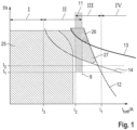
- figure 1 shows the switch-off time t plotted against a current I batt of the high-voltage storage device (electrochemical energy storage device).
- a short-circuit current I batt is so low below a limit I3 that all line sections of the potential short-circuit path remain undamaged.
- I3 a limit of the electrochemical energy store
- none of the security devices to be provided according to the invention are set up to secure this operating area. Of course, this does not mean that a short-circuit current in this range should be reasonably accepted. Only protection against overheating and any consequential damage is not required.
- An operational area IV is in conventionally protected by a fuse.
- the corresponding characteristic curve 12 for the strength of the safety fuse describes the turn-off time t over the current I batt .
- the characteristic curve 13 describes the overload limit of the first line section, in other words, for example, a line with a cross section of 35 mm 2 . Above the point of intersection of the fuse characteristic 12 and the line characteristic 13, this line is thermally overloaded in the event of an overload or short circuit, since the safety fuse in this area 26 does not reliably trip.
- the characteristic curve 14 describes the overload limit of the second line section, in other words, for example, a line with a cross section of 16 mm 2 . Above the point of intersection of the fuse characteristic 12 and the line characteristic 14, this line is thermally overloaded in the event of an overload or short circuit, since the safety fuse in this area 27 does not reliably trip.
- an area below these critical characteristic map points (high-voltage storage currents I batt ) must therefore be protected as area III by means of overcurrent detection as part of the second safety device.
- This range extends between the currents I2 and I1.
- the cell undervoltage shutdown can be used according to the invention as a component of the second safety device.
- the switch-off time of the second safety device is dimensioned in such a way that the maximum permissible switch-off time t 2 for protecting the weakest line section is not exceeded and at the same time a minimum time t 1 is exceeded in order to avoid overloading the contactors and to enable the safety fuse to trip.
- This time characteristic of the second safety device is due to the fact that the level of the overload or short-circuit current that is finally set is initially unknown.
- the lower limit of the overcurrent detection I2 must be greater than the Operating range of the first line section 25 are defined.
- the upper limit of the undervoltage shutdown 9 is above the minimum limit of the overcurrent shutdown I2, so that an overlapping area 11 results.
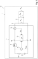
- FIG. 2 shows a vehicle electrical system 10 as a power supply.
- This includes a high-voltage battery 3 as an electrochemical energy store.
- a separating element eg a safety fuse
- an electrochemical cell 24 merely being a symbol for a large number of electrochemical cells.
- One or more separating elements (for example contactors) 8a, 8b are set up to connect electrical lines coming from the electrochemical cell 24 to the periphery or to separate them from it.
- the high-voltage battery also includes a current sensor 7a and a voltage sensor 7b, with the voltage sensor 7b being to be understood merely as a symbol. It can stand for a large number of individual cell voltage measurements or as a total or partial voltage measurement.
- a microcontroller 7c integrated in the high-voltage battery 3 .
- the microcontroller 7c controls the contactors 8a, 8b for disconnecting or connecting the electrical lines 5, 6 from the electrochemical cell 24.
- Electrical loads R L1 and R L2 are connected to the high-voltage battery 3 via electrical lines.
- a second line section 6 is shown as an example, which should lead electrical energy originating from the high-voltage battery 3 to the first load R L2 via a first line section 5 . Because of the short circuit R KS , there is a short circuit path across the line sections 5 and 6 through which a short circuit current flows.
- the short-circuit current can be interrupted by opening the contactors 8a, 8b using the current sensor 7a or the cell voltage measurement 7b of the microcontroller 7c in conjunction with the contactors 8a, 8b as a second safety device.
Landscapes
- Protection Of Static Devices (AREA)
- Emergency Protection Circuit Devices (AREA)
- Charge And Discharge Circuits For Batteries Or The Like (AREA)
Claims (4)
- Arrangement (1) de protection électrique d'un premier état opérationnel dans un réseau électrique (10) avec une résistance interne de source, variable en fonction du système, en fonction du vieillissement et fonction de la température, d'une batterie de traction à haute tension (3) pour un moyen de transport pouvant être propulsé électriquement, comprenant :- un premier dispositif de sécurité (4) sous la forme d'un fusible dont le comportement de déclenchement en vue de protéger le réseau électrique (10) contre une charge prédéfinie est, il est vrai, suffisant dans un deuxième état opérationnel, mais pas dans le premier état opérationnel, la batterie de traction (3) présentant, dans le premier état opérationnel, une résistance interne de source plus élevée que dans le deuxième état opérationnel, et- un deuxième dispositif de sécurité (7a, 7b, 7c, 8a, 8b), lequel est conçu pour protéger le réseau électrique (10) contre la charge qui, dans le premier état opérationnel, se produit au-dessous du comportement de déclenchement du premier dispositif de sécurité (4), le deuxième dispositif de sécurité (7a, 7b, 7c, 8a, 8b) comprenant un dispositif de mesure de tension (7b, 7c) pour la batterie de traction (3), caractérisé en ce que le deuxième dispositif de sécurité (7a, 7b, 7c, 8a, 8b) est conçu pour, en cas de déclenchement, ouvrir un élément sectionneur sous la forme d'un contacteur (8a, 8b) en vue de séparer la batterie de traction (3) du réseau électrique (10), le deuxième dispositif de sécurité (7a, 7b, 7c, 8a, 8b) comprenant en outre- un élément de déconnexion par surintensité comprenant un dispositif de mesure de courant (7a, 7c) et une valeur de seuil de courant (12) pour la déconnexion de surintensité et une valeur de seuil de tension pour l'élément de déconnexion par tension insuffisante sur un courant (Ibatt) à travers la batterie de traction à haute tension (3) et la résistance interne de source de la batterie de traction à haute tension (3) étant définies de telle sorte que les plages de déclenchement (II, III) de l'élément de déconnexion par surintensité et de l'élément de déconnexion par tension insuffisante sur le courant (Ibatt) à travers la batterie de traction à haute tension (3) sont au moins adjacentes l'une à l'autre, notamment se chevauchent (11),la batterie de traction (3) possédant des cellules branchées en série et le nombre total de cellules branchées en série de la batterie de traction (3), multiplié par une tension de cellule individuelle minimale lors du déclenchement de l'élément de déconnexion par tension insuffisante divisée par une valeur de seuil de courant inférieure (2) lors du déclenchement de l'élément de déconnexion par surintensité, étant supérieur à une résistance de court-circuit maximale à supposer d'un trajet de court-circuit potentiel (2),une deuxième portion de ligne (6) présentant une section de ligne plus faible qu'une première section de ligne (5) du trajet de court-circuit potentiel (2), et le point de rupture du premier dispositif de sécurité (4) pour la protection de la deuxième portion de ligne (6) dans le premier état opérationnel de la batterie de traction (3) étant insuffisamment dimensionné.
- Arrangement selon la revendication 1, le deuxième dispositif de sécurité (7a, 7b, 7c, 8a, 8b) étant conçu pour présenter une inertie telle pour le cas de déclenchement que, d'une part, le trajet de court-circuit potentiel (2) est protégé de manière fiable même en l'absence de déclenchement du premier dispositif de sécurité (4) et en ce que d'autre part, le premier dispositif de sécurité (4), en-dehors du premier état opérationnel, se déclenche avant le deuxième dispositif de sécurité (7a, 7b, 7c, 8a, 8b).
- Arrangement selon la revendication 2, une inertie du deuxième dispositif de sécurité (7a, 7b, 7c, 8a, 8b) étant appropriée pour inhiber un comportement de déclenchement dans le cas de pointes de courant de courte durée, notamment aussi des interventions de régulation de courte durée correspondantes.
- Moyen de transport comprenant une batterie de traction (3) et un arrangement (1) selon l'une des revendications précédentes.
Applications Claiming Priority (2)
| Application Number | Priority Date | Filing Date | Title |
|---|---|---|---|
| DE102013214726.0A DE102013214726A1 (de) | 2013-07-29 | 2013-07-29 | Anordnung zur elektrischen Absicherung eines potentiellen Kurzschlusses bzw. einer Überlast in einem Gleichstromnetz mit systembedingten, variablem Quellinnenwiderstand |
| PCT/EP2014/064392 WO2015014568A1 (fr) | 2013-07-29 | 2014-07-07 | Système permettant la protection électrique par fusible contre un court-circuit potentiel ou une surcharge dans un réseau à courant continu présentant une résistance intérieure de source variable dépendant du système |
Publications (2)
| Publication Number | Publication Date |
|---|---|
| EP3028357A1 EP3028357A1 (fr) | 2016-06-08 |
| EP3028357B1 true EP3028357B1 (fr) | 2023-06-07 |
Family
ID=51210429
Family Applications (1)
| Application Number | Title | Priority Date | Filing Date |
|---|---|---|---|
| EP14739729.3A Active EP3028357B1 (fr) | 2013-07-29 | 2014-07-07 | Système permettant la protection électrique par fusible contre un court-circuit potentiel ou une surcharge dans un réseau à courant continu présentant une résistance intérieure de source variable dépendant du système |
Country Status (5)
| Country | Link |
|---|---|
| US (1) | US10079483B2 (fr) |
| EP (1) | EP3028357B1 (fr) |
| CN (1) | CN105324897B (fr) |
| DE (1) | DE102013214726A1 (fr) |
| WO (1) | WO2015014568A1 (fr) |
Families Citing this family (31)
| Publication number | Priority date | Publication date | Assignee | Title |
|---|---|---|---|---|
| DE102015201899B4 (de) * | 2015-02-04 | 2021-11-04 | Bayerische Motoren Werke Aktiengesellschaft | Verfahren zur Absicherung eines Hochvolt-Bordnetzes eines Kraftfahrzeugs mit einer ersten und einer zweiten Energiequelle, Computerprogrammprodukt und Kraftfahrzeug |
| DE102015105426B4 (de) | 2015-04-09 | 2022-06-02 | Intilion Gmbh | Sicherheitsvorrichtung für einen wiederaufladbaren elektrischen Energiespeicher, Verfahren zur Unterbindung eines elektrischen Stromflusses eines wiederaufladbaren elektrischen Energiespeichers und Batteriesystem mit dieser Sicherheitsvorrichtung |
| DE102016013560A1 (de) * | 2015-11-17 | 2017-05-18 | Marquardt Gmbh | Batteriesystem |
| DE102016216213A1 (de) * | 2016-08-29 | 2018-03-01 | Robert Bosch Gmbh | Verfahren und Schaltungsanordnung zum Trennen einer Spannungsquelle von mindestens einem Verbraucher |
| US10656215B2 (en) | 2016-11-07 | 2020-05-19 | Nissan Motor Co., Ltd. | Short circuit detection device |
| FR3059164B1 (fr) * | 2016-11-18 | 2020-09-18 | Continental Automotive France | Dispositif de protection d'un calculateur electronique contre un court-circuit |
| FR3059115B1 (fr) * | 2016-11-23 | 2019-05-10 | Sagemcom Broadband Sas | Systeme de gestion de consommation electrique dans un appareil |
| DE102016224810A1 (de) * | 2016-12-13 | 2018-06-14 | Bayerische Motoren Werke Aktiengesellschaft | Kraftfahrzeug mit einem Elektromotor, insbesondere Hybrid- oder Elektrofahrzeug |
| DE102017205612A1 (de) * | 2017-04-03 | 2018-10-04 | Robert Bosch Gmbh | Verfahren zur Ansteuerung einer Trennvorrichtung eines elektrochemischen Energiespeichers |
| DE102017107889B4 (de) * | 2017-04-12 | 2020-11-26 | Eberspächer Controls Landau Gmbh & Co. Kg | Sicherheitsüberwachungseinheit für eine Batterie in einem Bordnetz eines Fahrzeugs sowie Batteriebaugruppe für ein Bordnetz eines Fahrzeugs mit einer solchen Sicherheitsüberwachungseinheit |
| EP3389156B1 (fr) * | 2017-04-13 | 2021-06-02 | Andreas Stihl AG & Co. KG | Procédé de fonctionnement d'un système d'appareil forestier et/ou de jardin électrique, circuit électronique de protection, système de circuit électronique de protection, système d'accumulateur et système d'appareil forestier et/ou de jardin électrique |
| FR3090888B1 (fr) * | 2018-12-19 | 2020-11-27 | Continental Automotive France | Dispositif de détection automatique de couplage entre dispositifs électronique |
| DE102019202164A1 (de) | 2019-02-19 | 2020-08-20 | Audi Ag | Schutzvorrichtung, Batterie, Kraftfahrzeug und Verfahren zum Abschalten einer Batteriezelle |
| DE102019203918A1 (de) | 2019-03-21 | 2020-09-24 | Leoni Bordnetz-Systeme Gmbh | Bordnetz für ein Fahrzeug sowie Verfahren zur Auslegung einer elektrischen Leitung eines Bordnetzes |
| DE102019203977B4 (de) * | 2019-03-22 | 2020-12-24 | Siemens Aktiengesellschaft | Schutzschalteinrichtung für Gleichspannung und Gleichspannungsabzweig mit Schutzschalteinrichtung |
| US11108223B2 (en) * | 2019-05-15 | 2021-08-31 | Johnson Controls Fire Protection LP | Abnormal impedance fault isolation |
| US11132890B2 (en) | 2019-05-15 | 2021-09-28 | Johnson Controls Fire Protection LP | Fault isolation locality |
| CN110970866A (zh) * | 2019-11-14 | 2020-04-07 | 华为技术有限公司 | 一种接触器控制装置和供电系统 |
| US11176806B1 (en) | 2019-12-06 | 2021-11-16 | Johnson Controls Fire Protection LP | Erratic short-circuit detection |
| DE102020201632B4 (de) | 2020-02-11 | 2025-07-17 | Volkswagen Aktiengesellschaft | Schaltungsanordnung und Verfahren zum Trennen einer Spannungsquelle von mindestens einem Verbraucher |
| DE102020210794B3 (de) | 2020-08-26 | 2021-09-30 | Siemens Aktiengesellschaft | Batteriespeichervorrichtung, Parallelschaltung von Batteriespeichervorrichtungen und Verfahren zum Betreiben einer Batteriespeichervorrichtung |
| BE1029566B1 (de) * | 2021-07-05 | 2023-02-06 | Phoenix Contact Gmbh & Co | Gleichspannungsschaltgerät mit Erdschlussschutz |
| EP4190499A1 (fr) | 2021-12-01 | 2023-06-07 | Hilti Aktiengesellschaft | Système, interface, machine-outil et dispositif d'alimentation en énergie |
| EP4190498A1 (fr) | 2021-12-01 | 2023-06-07 | Hilti Aktiengesellschaft | Systèmes comprenant des machines-outils et des dispositifs d'alimentation en énergie, ainsi que dispositif d'alimentation en énergie |
| EP4441863A1 (fr) | 2021-12-01 | 2024-10-09 | Hilti Aktiengesellschaft | Dispositif d'alimentation en énergie avec au moins un élément de séparation de courant |
| EP4210195A1 (fr) * | 2022-01-11 | 2023-07-12 | Hilti Aktiengesellschaft | Dispositif d'alimentation électrique pourvu d'au moins un élément séparant le courant |
| JP2024545625A (ja) | 2021-12-01 | 2024-12-10 | ヒルティ アクチエンゲゼルシャフト | 機械工具と電力供給装置とを有するシステム、インターフェース及び電力供給装置 |
| DE102022114140A1 (de) * | 2022-06-03 | 2023-12-14 | TRUMPF Hüttinger GmbH + Co. KG | Sicherungs-Auslösebeschleunigungsanordnung, Stromwandleranordnung und Energiespeichersystem |
| CN115173372B (zh) * | 2022-07-26 | 2024-09-03 | 广州小鹏汽车科技有限公司 | 短路保护电路、动力电池包以及车辆 |
| CN115498595A (zh) * | 2022-09-09 | 2022-12-20 | 广州小鹏汽车科技有限公司 | 短路保护电路、动力电池包以及车辆 |
| US20250389782A1 (en) * | 2024-06-20 | 2025-12-25 | GM Global Technology Operations LLC | Internal short circuit detection |
Citations (2)
| Publication number | Priority date | Publication date | Assignee | Title |
|---|---|---|---|---|
| US4509102A (en) * | 1983-03-08 | 1985-04-02 | Canadian Patents & Dev. Limited | Voltage controlled current switch with short circuit protection |
| US20120106013A1 (en) * | 2010-10-29 | 2012-05-03 | Green Solution Technology Co., Ltd. | Current sense circuit and battery over-current protection controller |
Family Cites Families (10)
| Publication number | Priority date | Publication date | Assignee | Title |
|---|---|---|---|---|
| JP2959424B2 (ja) * | 1995-02-23 | 1999-10-06 | 住友電装株式会社 | 自動車の電流分配システム |
| DE10103336C1 (de) * | 2001-01-25 | 2002-12-05 | Dialog Semiconductor Gmbh | Lade-/Entlade-Schutzschaltung für eine wiederaufladbare Batterie |
| US7433794B1 (en) * | 2007-07-18 | 2008-10-07 | Tesla Motors, Inc. | Mitigation of propagation of thermal runaway in a multi-cell battery pack |
| DE102008053074A1 (de) * | 2008-07-09 | 2010-01-21 | Siemens Aktiengesellschaft | Schnellschalteinrichtung für eine Hochleistungs-Batterie in einem Gleichstrominselnetz |
| JP5675045B2 (ja) * | 2008-11-26 | 2015-02-25 | 三洋電機株式会社 | バッテリシステム |
| JP5381664B2 (ja) * | 2009-12-02 | 2014-01-08 | トヨタ自動車株式会社 | 組電池の異常検出装置 |
| US8885308B2 (en) * | 2011-07-18 | 2014-11-11 | Crane Electronics, Inc. | Input control apparatus and method with inrush current, under and over voltage handling |
| AT511820B1 (de) | 2011-11-03 | 2013-03-15 | Avl List Gmbh | Batteriesystem |
| DE102011121604B4 (de) * | 2011-12-17 | 2024-08-29 | Volkswagen Aktiengesellschaft | Verfahren zum Schützen eines elektrischen oder elektronischen Systems und Vorrichtung |
| US9194904B2 (en) * | 2013-06-20 | 2015-11-24 | GM Global Technology Operations LLC | Systems and methods for detecting leakage paths in a battery sensing circuit |
-
2013
- 2013-07-29 DE DE102013214726.0A patent/DE102013214726A1/de not_active Withdrawn
-
2014
- 2014-07-07 EP EP14739729.3A patent/EP3028357B1/fr active Active
- 2014-07-07 WO PCT/EP2014/064392 patent/WO2015014568A1/fr not_active Ceased
- 2014-07-07 CN CN201480034760.2A patent/CN105324897B/zh active Active
-
2015
- 2015-11-19 US US14/945,489 patent/US10079483B2/en active Active
Patent Citations (2)
| Publication number | Priority date | Publication date | Assignee | Title |
|---|---|---|---|---|
| US4509102A (en) * | 1983-03-08 | 1985-04-02 | Canadian Patents & Dev. Limited | Voltage controlled current switch with short circuit protection |
| US20120106013A1 (en) * | 2010-10-29 | 2012-05-03 | Green Solution Technology Co., Ltd. | Current sense circuit and battery over-current protection controller |
Also Published As
| Publication number | Publication date |
|---|---|
| CN105324897B (zh) | 2018-03-30 |
| DE102013214726A1 (de) | 2015-01-29 |
| US20160072269A1 (en) | 2016-03-10 |
| CN105324897A (zh) | 2016-02-10 |
| EP3028357A1 (fr) | 2016-06-08 |
| WO2015014568A1 (fr) | 2015-02-05 |
| US10079483B2 (en) | 2018-09-18 |
Similar Documents
| Publication | Publication Date | Title |
|---|---|---|
| EP3028357B1 (fr) | Système permettant la protection électrique par fusible contre un court-circuit potentiel ou une surcharge dans un réseau à courant continu présentant une résistance intérieure de source variable dépendant du système | |
| DE112019005683B4 (de) | Schnellbatterietrennsystem für Hochstromschaltungen | |
| DE102014214840B4 (de) | Vorrichtung zur Überwachung eines Hochvolt-Bordnetzes eines elektrisch betriebenen Fahrzeugs auf das Vorliegen einer Überlastung | |
| DE102013106370B4 (de) | Schaltungsschutz | |
| EP2777979A2 (fr) | Module de batterie électrique à sécurité intrinsèque avec circuit de décharge ultra-rapide et procédé de surveillance d'un module de batterie | |
| DE102015107718B4 (de) | Vorrichtung und Verfahren zum Absichern einer Bordnetz-Komponente eines Fahrzeug-Bordnetzes | |
| DE102013204526A1 (de) | Batteriezelleinheit mit einer Batteriezelle und einer Überwachungs- und Ansteuerungseinheit zur Überwachung der Batteriezelle und Verfahren zur Überwachung einer Batteriezelle | |
| DE102009023801A1 (de) | Sicherungsvorrichtung mit pyrotechnischer Sicherung | |
| WO2022002496A1 (fr) | Dispositif pour sécuriser en particulier des charges liées à la sécurité dans un véhicule automobile | |
| DE102013204541A1 (de) | Batteriezelleinheit mit Batteriezelle und ultraschneller Entladeschaltung und Verfahren zur Überwachung einer Batteriezelle | |
| DE102013204534A1 (de) | Batteriezelleinrichtung mit Kurzschlusssicherheitsfunktion und Verfahren zum Überwachen einer Batteriezelle | |
| DE102014205116A1 (de) | Batteriezelleinrichtung mit einer Batteriezelle und einer Strombegrenzungsschaltung und Verfahren zum Begrenzen eines über die Batteriezelle und die Batteriezellanschlüsse der Batteriezelle fließenden Stromes | |
| DE112022002357T5 (de) | Fahrzeugseitig angeordnete umschaltvorrichtung | |
| WO2019149416A1 (fr) | Dispositif de protection d'au moins un consommateur | |
| DE102015000576B4 (de) | Kraftfahrzeug mit Schaltvorrichtung für eine bordnetzbetriebene Komponente | |
| EP2779354B1 (fr) | Module de batterie électrique à sécurité intrinsèque avec tension de sortie à polarité inversable et procédé de surveillance d'un module de batterie | |
| DE102013012578B4 (de) | Vorrichtung zum Absichern einer elektrischen Leitung sowie Verfahren zum Betreiben einer auf einer elektrischen Leitung angeordneten Vorrichtung | |
| DE102013204538A1 (de) | Batteriezellmodul und Verfahren zum Betreiben eines Batteriezellmoduls | |
| DE102016121447A1 (de) | Vorrichtung und Verfahren zum Absichern einer Bordnetzkomponente eines Fahrzeug-Bordnetzes | |
| DE102017201488B4 (de) | Detektieren eines Kurzschlusses in einem elektrischen Energieverteilungsnetz | |
| WO2022233881A1 (fr) | Unité de contact au sol | |
| DE102013204509A1 (de) | Batteriemodul und Verfahren zum Überwachen eines Batteriemoduls | |
| EP2961019A1 (fr) | Dispositif de protection contre un courant excessif pour un vehicule automobile, dispositif de connexion electrique et vehicule automobile | |
| DE10009775A1 (de) | Einrichtung und Verfahren zur Überstrom-Absicherung von elektrischen Bordnetzen | |
| WO2024179706A1 (fr) | Dispositif et procédé d'alimentation d'une charge relative à la sécurité dans un véhicule automobile |
Legal Events
| Date | Code | Title | Description |
|---|---|---|---|
| PUAI | Public reference made under article 153(3) epc to a published international application that has entered the european phase |
Free format text: ORIGINAL CODE: 0009012 |
|
| 17P | Request for examination filed |
Effective date: 20160126 |
|
| AK | Designated contracting states |
Kind code of ref document: A1 Designated state(s): AL AT BE BG CH CY CZ DE DK EE ES FI FR GB GR HR HU IE IS IT LI LT LU LV MC MK MT NL NO PL PT RO RS SE SI SK SM TR |
|
| AX | Request for extension of the european patent |
Extension state: BA ME |
|
| DAX | Request for extension of the european patent (deleted) | ||
| STAA | Information on the status of an ep patent application or granted ep patent |
Free format text: STATUS: EXAMINATION IS IN PROGRESS |
|
| 17Q | First examination report despatched |
Effective date: 20180613 |
|
| GRAP | Despatch of communication of intention to grant a patent |
Free format text: ORIGINAL CODE: EPIDOSNIGR1 |
|
| STAA | Information on the status of an ep patent application or granted ep patent |
Free format text: STATUS: GRANT OF PATENT IS INTENDED |
|
| INTG | Intention to grant announced |
Effective date: 20230228 |
|
| GRAS | Grant fee paid |
Free format text: ORIGINAL CODE: EPIDOSNIGR3 |
|
| GRAA | (expected) grant |
Free format text: ORIGINAL CODE: 0009210 |
|
| STAA | Information on the status of an ep patent application or granted ep patent |
Free format text: STATUS: THE PATENT HAS BEEN GRANTED |
|
| AK | Designated contracting states |
Kind code of ref document: B1 Designated state(s): AL AT BE BG CH CY CZ DE DK EE ES FI FR GB GR HR HU IE IS IT LI LT LU LV MC MK MT NL NO PL PT RO RS SE SI SK SM TR |
|
| REG | Reference to a national code |
Ref country code: GB Ref legal event code: FG4D Free format text: NOT ENGLISH |
|
| P01 | Opt-out of the competence of the unified patent court (upc) registered |
Effective date: 20230502 |
|
| REG | Reference to a national code |
Ref country code: CH Ref legal event code: EP Ref country code: AT Ref legal event code: REF Ref document number: 1577779 Country of ref document: AT Kind code of ref document: T Effective date: 20230615 |
|
| REG | Reference to a national code |
Ref country code: DE Ref legal event code: R096 Ref document number: 502014016587 Country of ref document: DE |
|
| P02 | Opt-out of the competence of the unified patent court (upc) changed |
Effective date: 20230802 |
|
| REG | Reference to a national code |
Ref country code: LT Ref legal event code: MG9D |
|
| REG | Reference to a national code |
Ref country code: NL Ref legal event code: MP Effective date: 20230607 |
|
| PG25 | Lapsed in a contracting state [announced via postgrant information from national office to epo] |
Ref country code: SE Free format text: LAPSE BECAUSE OF FAILURE TO SUBMIT A TRANSLATION OF THE DESCRIPTION OR TO PAY THE FEE WITHIN THE PRESCRIBED TIME-LIMIT Effective date: 20230607 Ref country code: NO Free format text: LAPSE BECAUSE OF FAILURE TO SUBMIT A TRANSLATION OF THE DESCRIPTION OR TO PAY THE FEE WITHIN THE PRESCRIBED TIME-LIMIT Effective date: 20230907 Ref country code: ES Free format text: LAPSE BECAUSE OF FAILURE TO SUBMIT A TRANSLATION OF THE DESCRIPTION OR TO PAY THE FEE WITHIN THE PRESCRIBED TIME-LIMIT Effective date: 20230607 |
|
| PG25 | Lapsed in a contracting state [announced via postgrant information from national office to epo] |
Ref country code: RS Free format text: LAPSE BECAUSE OF FAILURE TO SUBMIT A TRANSLATION OF THE DESCRIPTION OR TO PAY THE FEE WITHIN THE PRESCRIBED TIME-LIMIT Effective date: 20230607 Ref country code: NL Free format text: LAPSE BECAUSE OF FAILURE TO SUBMIT A TRANSLATION OF THE DESCRIPTION OR TO PAY THE FEE WITHIN THE PRESCRIBED TIME-LIMIT Effective date: 20230607 Ref country code: LV Free format text: LAPSE BECAUSE OF FAILURE TO SUBMIT A TRANSLATION OF THE DESCRIPTION OR TO PAY THE FEE WITHIN THE PRESCRIBED TIME-LIMIT Effective date: 20230607 Ref country code: LT Free format text: LAPSE BECAUSE OF FAILURE TO SUBMIT A TRANSLATION OF THE DESCRIPTION OR TO PAY THE FEE WITHIN THE PRESCRIBED TIME-LIMIT Effective date: 20230607 Ref country code: HR Free format text: LAPSE BECAUSE OF FAILURE TO SUBMIT A TRANSLATION OF THE DESCRIPTION OR TO PAY THE FEE WITHIN THE PRESCRIBED TIME-LIMIT Effective date: 20230607 Ref country code: GR Free format text: LAPSE BECAUSE OF FAILURE TO SUBMIT A TRANSLATION OF THE DESCRIPTION OR TO PAY THE FEE WITHIN THE PRESCRIBED TIME-LIMIT Effective date: 20230908 |
|
| PG25 | Lapsed in a contracting state [announced via postgrant information from national office to epo] |
Ref country code: FI Free format text: LAPSE BECAUSE OF FAILURE TO SUBMIT A TRANSLATION OF THE DESCRIPTION OR TO PAY THE FEE WITHIN THE PRESCRIBED TIME-LIMIT Effective date: 20230607 |
|
| PG25 | Lapsed in a contracting state [announced via postgrant information from national office to epo] |
Ref country code: SK Free format text: LAPSE BECAUSE OF FAILURE TO SUBMIT A TRANSLATION OF THE DESCRIPTION OR TO PAY THE FEE WITHIN THE PRESCRIBED TIME-LIMIT Effective date: 20230607 |
|
| PG25 | Lapsed in a contracting state [announced via postgrant information from national office to epo] |
Ref country code: IS Free format text: LAPSE BECAUSE OF FAILURE TO SUBMIT A TRANSLATION OF THE DESCRIPTION OR TO PAY THE FEE WITHIN THE PRESCRIBED TIME-LIMIT Effective date: 20231007 |
|
| PG25 | Lapsed in a contracting state [announced via postgrant information from national office to epo] |
Ref country code: SM Free format text: LAPSE BECAUSE OF FAILURE TO SUBMIT A TRANSLATION OF THE DESCRIPTION OR TO PAY THE FEE WITHIN THE PRESCRIBED TIME-LIMIT Effective date: 20230607 Ref country code: SK Free format text: LAPSE BECAUSE OF FAILURE TO SUBMIT A TRANSLATION OF THE DESCRIPTION OR TO PAY THE FEE WITHIN THE PRESCRIBED TIME-LIMIT Effective date: 20230607 Ref country code: RO Free format text: LAPSE BECAUSE OF FAILURE TO SUBMIT A TRANSLATION OF THE DESCRIPTION OR TO PAY THE FEE WITHIN THE PRESCRIBED TIME-LIMIT Effective date: 20230607 Ref country code: PT Free format text: LAPSE BECAUSE OF FAILURE TO SUBMIT A TRANSLATION OF THE DESCRIPTION OR TO PAY THE FEE WITHIN THE PRESCRIBED TIME-LIMIT Effective date: 20231009 Ref country code: IS Free format text: LAPSE BECAUSE OF FAILURE TO SUBMIT A TRANSLATION OF THE DESCRIPTION OR TO PAY THE FEE WITHIN THE PRESCRIBED TIME-LIMIT Effective date: 20231007 Ref country code: EE Free format text: LAPSE BECAUSE OF FAILURE TO SUBMIT A TRANSLATION OF THE DESCRIPTION OR TO PAY THE FEE WITHIN THE PRESCRIBED TIME-LIMIT Effective date: 20230607 Ref country code: CZ Free format text: LAPSE BECAUSE OF FAILURE TO SUBMIT A TRANSLATION OF THE DESCRIPTION OR TO PAY THE FEE WITHIN THE PRESCRIBED TIME-LIMIT Effective date: 20230607 |
|
| PG25 | Lapsed in a contracting state [announced via postgrant information from national office to epo] |
Ref country code: PL Free format text: LAPSE BECAUSE OF FAILURE TO SUBMIT A TRANSLATION OF THE DESCRIPTION OR TO PAY THE FEE WITHIN THE PRESCRIBED TIME-LIMIT Effective date: 20230607 |
|
| REG | Reference to a national code |
Ref country code: CH Ref legal event code: PL |
|
| REG | Reference to a national code |
Ref country code: DE Ref legal event code: R097 Ref document number: 502014016587 Country of ref document: DE |
|
| PG25 | Lapsed in a contracting state [announced via postgrant information from national office to epo] |
Ref country code: MC Free format text: LAPSE BECAUSE OF FAILURE TO SUBMIT A TRANSLATION OF THE DESCRIPTION OR TO PAY THE FEE WITHIN THE PRESCRIBED TIME-LIMIT Effective date: 20230607 |
|
| REG | Reference to a national code |
Ref country code: BE Ref legal event code: MM Effective date: 20230731 |
|
| PG25 | Lapsed in a contracting state [announced via postgrant information from national office to epo] |
Ref country code: LU Free format text: LAPSE BECAUSE OF NON-PAYMENT OF DUE FEES Effective date: 20230707 |
|
| PG25 | Lapsed in a contracting state [announced via postgrant information from national office to epo] |
Ref country code: MC Free format text: LAPSE BECAUSE OF FAILURE TO SUBMIT A TRANSLATION OF THE DESCRIPTION OR TO PAY THE FEE WITHIN THE PRESCRIBED TIME-LIMIT Effective date: 20230607 Ref country code: LU Free format text: LAPSE BECAUSE OF NON-PAYMENT OF DUE FEES Effective date: 20230707 |
|
| PLBE | No opposition filed within time limit |
Free format text: ORIGINAL CODE: 0009261 |
|
| STAA | Information on the status of an ep patent application or granted ep patent |
Free format text: STATUS: NO OPPOSITION FILED WITHIN TIME LIMIT |
|
| REG | Reference to a national code |
Ref country code: IE Ref legal event code: MM4A |
|
| PG25 | Lapsed in a contracting state [announced via postgrant information from national office to epo] |
Ref country code: DK Free format text: LAPSE BECAUSE OF FAILURE TO SUBMIT A TRANSLATION OF THE DESCRIPTION OR TO PAY THE FEE WITHIN THE PRESCRIBED TIME-LIMIT Effective date: 20230607 Ref country code: CH Free format text: LAPSE BECAUSE OF NON-PAYMENT OF DUE FEES Effective date: 20230731 |
|
| PG25 | Lapsed in a contracting state [announced via postgrant information from national office to epo] |
Ref country code: SI Free format text: LAPSE BECAUSE OF FAILURE TO SUBMIT A TRANSLATION OF THE DESCRIPTION OR TO PAY THE FEE WITHIN THE PRESCRIBED TIME-LIMIT Effective date: 20230607 |
|
| 26N | No opposition filed |
Effective date: 20240308 |
|
| PG25 | Lapsed in a contracting state [announced via postgrant information from national office to epo] |
Ref country code: SI Free format text: LAPSE BECAUSE OF FAILURE TO SUBMIT A TRANSLATION OF THE DESCRIPTION OR TO PAY THE FEE WITHIN THE PRESCRIBED TIME-LIMIT Effective date: 20230607 Ref country code: BE Free format text: LAPSE BECAUSE OF NON-PAYMENT OF DUE FEES Effective date: 20230731 |
|
| PG25 | Lapsed in a contracting state [announced via postgrant information from national office to epo] |
Ref country code: IE Free format text: LAPSE BECAUSE OF NON-PAYMENT OF DUE FEES Effective date: 20230707 |
|
| PG25 | Lapsed in a contracting state [announced via postgrant information from national office to epo] |
Ref country code: IE Free format text: LAPSE BECAUSE OF NON-PAYMENT OF DUE FEES Effective date: 20230707 |
|
| REG | Reference to a national code |
Ref country code: AT Ref legal event code: MM01 Ref document number: 1577779 Country of ref document: AT Kind code of ref document: T Effective date: 20230707 |
|
| PG25 | Lapsed in a contracting state [announced via postgrant information from national office to epo] |
Ref country code: AT Free format text: LAPSE BECAUSE OF NON-PAYMENT OF DUE FEES Effective date: 20230707 |
|
| PG25 | Lapsed in a contracting state [announced via postgrant information from national office to epo] |
Ref country code: AT Free format text: LAPSE BECAUSE OF NON-PAYMENT OF DUE FEES Effective date: 20230707 |
|
| PG25 | Lapsed in a contracting state [announced via postgrant information from national office to epo] |
Ref country code: BG Free format text: LAPSE BECAUSE OF FAILURE TO SUBMIT A TRANSLATION OF THE DESCRIPTION OR TO PAY THE FEE WITHIN THE PRESCRIBED TIME-LIMIT Effective date: 20230607 |
|
| PG25 | Lapsed in a contracting state [announced via postgrant information from national office to epo] |
Ref country code: BG Free format text: LAPSE BECAUSE OF FAILURE TO SUBMIT A TRANSLATION OF THE DESCRIPTION OR TO PAY THE FEE WITHIN THE PRESCRIBED TIME-LIMIT Effective date: 20230607 |
|
| PG25 | Lapsed in a contracting state [announced via postgrant information from national office to epo] |
Ref country code: CY Free format text: LAPSE BECAUSE OF FAILURE TO SUBMIT A TRANSLATION OF THE DESCRIPTION OR TO PAY THE FEE WITHIN THE PRESCRIBED TIME-LIMIT; INVALID AB INITIO Effective date: 20140707 |
|
| PG25 | Lapsed in a contracting state [announced via postgrant information from national office to epo] |
Ref country code: HU Free format text: LAPSE BECAUSE OF FAILURE TO SUBMIT A TRANSLATION OF THE DESCRIPTION OR TO PAY THE FEE WITHIN THE PRESCRIBED TIME-LIMIT; INVALID AB INITIO Effective date: 20140707 |
|
| PGFP | Annual fee paid to national office [announced via postgrant information from national office to epo] |
Ref country code: DE Payment date: 20250702 Year of fee payment: 12 |
|
| PGFP | Annual fee paid to national office [announced via postgrant information from national office to epo] |
Ref country code: IT Payment date: 20250731 Year of fee payment: 12 |
|
| PGFP | Annual fee paid to national office [announced via postgrant information from national office to epo] |
Ref country code: GB Payment date: 20250724 Year of fee payment: 12 |
|
| PGFP | Annual fee paid to national office [announced via postgrant information from national office to epo] |
Ref country code: FR Payment date: 20250723 Year of fee payment: 12 |
|
| PG25 | Lapsed in a contracting state [announced via postgrant information from national office to epo] |
Ref country code: TR Free format text: LAPSE BECAUSE OF FAILURE TO SUBMIT A TRANSLATION OF THE DESCRIPTION OR TO PAY THE FEE WITHIN THE PRESCRIBED TIME-LIMIT Effective date: 20230607 |