EP3028737A1 - Soupape de cathéter auto-obturante - Google Patents
Soupape de cathéter auto-obturante Download PDFInfo
- Publication number
- EP3028737A1 EP3028737A1 EP14196068.2A EP14196068A EP3028737A1 EP 3028737 A1 EP3028737 A1 EP 3028737A1 EP 14196068 A EP14196068 A EP 14196068A EP 3028737 A1 EP3028737 A1 EP 3028737A1
- Authority
- EP
- European Patent Office
- Prior art keywords
- self
- sealing
- valve
- tubular part
- catheter
- Prior art date
- Legal status (The legal status is an assumption and is not a legal conclusion. Google has not performed a legal analysis and makes no representation as to the accuracy of the status listed.)
- Withdrawn
Links
- 238000007789 sealing Methods 0.000 title claims abstract description 141
- 230000002093 peripheral effect Effects 0.000 claims abstract description 11
- 238000002347 injection Methods 0.000 claims description 25
- 239000007924 injection Substances 0.000 claims description 25
- 230000007423 decrease Effects 0.000 claims description 2
- 239000008280 blood Substances 0.000 abstract description 10
- 210000004369 blood Anatomy 0.000 abstract description 10
- 230000004888 barrier function Effects 0.000 abstract description 3
- 241001115402 Ebolavirus Species 0.000 abstract description 2
- 201000010099 disease Diseases 0.000 abstract description 2
- 208000037265 diseases, disorders, signs and symptoms Diseases 0.000 abstract description 2
- 208000006454 hepatitis Diseases 0.000 abstract description 2
- 231100000283 hepatitis Toxicity 0.000 abstract description 2
- 230000007246 mechanism Effects 0.000 abstract description 2
- 210000004204 blood vessel Anatomy 0.000 description 10
- 239000012530 fluid Substances 0.000 description 9
- 238000012360 testing method Methods 0.000 description 7
- 230000036772 blood pressure Effects 0.000 description 6
- 230000000052 comparative effect Effects 0.000 description 5
- 230000023597 hemostasis Effects 0.000 description 4
- 238000001802 infusion Methods 0.000 description 4
- 239000003978 infusion fluid Substances 0.000 description 4
- 238000003780 insertion Methods 0.000 description 4
- 230000037431 insertion Effects 0.000 description 4
- 210000001765 aortic valve Anatomy 0.000 description 3
- 238000013461 design Methods 0.000 description 3
- 238000000338 in vitro Methods 0.000 description 3
- 238000009533 lab test Methods 0.000 description 3
- 241001465754 Metazoa Species 0.000 description 2
- 241000282887 Suidae Species 0.000 description 2
- 239000011324 bead Substances 0.000 description 2
- 230000008901 benefit Effects 0.000 description 2
- 230000017531 blood circulation Effects 0.000 description 2
- 230000006835 compression Effects 0.000 description 2
- 238000007906 compression Methods 0.000 description 2
- 238000010276 construction Methods 0.000 description 2
- 238000011109 contamination Methods 0.000 description 2
- 238000006073 displacement reaction Methods 0.000 description 2
- 230000007774 longterm Effects 0.000 description 2
- 230000036244 malformation Effects 0.000 description 2
- 239000000463 material Substances 0.000 description 2
- 229920001296 polysiloxane Polymers 0.000 description 2
- 230000004044 response Effects 0.000 description 2
- 230000001954 sterilising effect Effects 0.000 description 2
- 238000004659 sterilization and disinfection Methods 0.000 description 2
- 229910000831 Steel Inorganic materials 0.000 description 1
- 229920004482 WACKER® Polymers 0.000 description 1
- 239000000853 adhesive Substances 0.000 description 1
- 230000001070 adhesive effect Effects 0.000 description 1
- 238000000429 assembly Methods 0.000 description 1
- 230000000712 assembly Effects 0.000 description 1
- 239000003795 chemical substances by application Substances 0.000 description 1
- 230000000295 complement effect Effects 0.000 description 1
- 230000008878 coupling Effects 0.000 description 1
- 238000010168 coupling process Methods 0.000 description 1
- 238000005859 coupling reaction Methods 0.000 description 1
- 230000007547 defect Effects 0.000 description 1
- 230000001419 dependent effect Effects 0.000 description 1
- 239000003814 drug Substances 0.000 description 1
- 229940079593 drug Drugs 0.000 description 1
- 238000011156 evaluation Methods 0.000 description 1
- 238000001990 intravenous administration Methods 0.000 description 1
- 238000004519 manufacturing process Methods 0.000 description 1
- 238000000034 method Methods 0.000 description 1
- 229920002379 silicone rubber Polymers 0.000 description 1
- 239000007787 solid Substances 0.000 description 1
- 239000010959 steel Substances 0.000 description 1
- 238000012414 sterilization procedure Methods 0.000 description 1
- 230000002459 sustained effect Effects 0.000 description 1
- 230000007704 transition Effects 0.000 description 1
- 210000003462 vein Anatomy 0.000 description 1
Images


Classifications
-
- A—HUMAN NECESSITIES
- A61—MEDICAL OR VETERINARY SCIENCE; HYGIENE
- A61M—DEVICES FOR INTRODUCING MEDIA INTO, OR ONTO, THE BODY; DEVICES FOR TRANSDUCING BODY MEDIA OR FOR TAKING MEDIA FROM THE BODY; DEVICES FOR PRODUCING OR ENDING SLEEP OR STUPOR
- A61M25/00—Catheters; Hollow probes
- A61M25/01—Introducing, guiding, advancing, emplacing or holding catheters
- A61M25/06—Body-piercing guide needles or the like
- A61M25/0606—"Over-the-needle" catheter assemblies, e.g. I.V. catheters
-
- A—HUMAN NECESSITIES
- A61—MEDICAL OR VETERINARY SCIENCE; HYGIENE
- A61M—DEVICES FOR INTRODUCING MEDIA INTO, OR ONTO, THE BODY; DEVICES FOR TRANSDUCING BODY MEDIA OR FOR TAKING MEDIA FROM THE BODY; DEVICES FOR PRODUCING OR ENDING SLEEP OR STUPOR
- A61M25/00—Catheters; Hollow probes
- A61M25/0097—Catheters; Hollow probes characterised by the hub
-
- A—HUMAN NECESSITIES
- A61—MEDICAL OR VETERINARY SCIENCE; HYGIENE
- A61M—DEVICES FOR INTRODUCING MEDIA INTO, OR ONTO, THE BODY; DEVICES FOR TRANSDUCING BODY MEDIA OR FOR TAKING MEDIA FROM THE BODY; DEVICES FOR PRODUCING OR ENDING SLEEP OR STUPOR
- A61M25/00—Catheters; Hollow probes
- A61M25/01—Introducing, guiding, advancing, emplacing or holding catheters
- A61M25/06—Body-piercing guide needles or the like
- A61M25/0662—Guide tubes
-
- A—HUMAN NECESSITIES
- A61—MEDICAL OR VETERINARY SCIENCE; HYGIENE
- A61M—DEVICES FOR INTRODUCING MEDIA INTO, OR ONTO, THE BODY; DEVICES FOR TRANSDUCING BODY MEDIA OR FOR TAKING MEDIA FROM THE BODY; DEVICES FOR PRODUCING OR ENDING SLEEP OR STUPOR
- A61M39/00—Tubes, tube connectors, tube couplings, valves, access sites or the like, specially adapted for medical use
- A61M39/02—Access sites
- A61M39/04—Access sites having pierceable self-sealing members
- A61M39/045—Access sites having pierceable self-sealing members pre-slit to be pierced by blunt instrument
-
- A—HUMAN NECESSITIES
- A61—MEDICAL OR VETERINARY SCIENCE; HYGIENE
- A61M—DEVICES FOR INTRODUCING MEDIA INTO, OR ONTO, THE BODY; DEVICES FOR TRANSDUCING BODY MEDIA OR FOR TAKING MEDIA FROM THE BODY; DEVICES FOR PRODUCING OR ENDING SLEEP OR STUPOR
- A61M39/00—Tubes, tube connectors, tube couplings, valves, access sites or the like, specially adapted for medical use
- A61M39/02—Access sites
- A61M39/06—Haemostasis valves, i.e. gaskets sealing around a needle, catheter or the like, closing on removal thereof
- A61M39/0606—Haemostasis valves, i.e. gaskets sealing around a needle, catheter or the like, closing on removal thereof without means for adjusting the seal opening or pressure
-
- A—HUMAN NECESSITIES
- A61—MEDICAL OR VETERINARY SCIENCE; HYGIENE
- A61M—DEVICES FOR INTRODUCING MEDIA INTO, OR ONTO, THE BODY; DEVICES FOR TRANSDUCING BODY MEDIA OR FOR TAKING MEDIA FROM THE BODY; DEVICES FOR PRODUCING OR ENDING SLEEP OR STUPOR
- A61M39/00—Tubes, tube connectors, tube couplings, valves, access sites or the like, specially adapted for medical use
- A61M39/22—Valves or arrangement of valves
- A61M39/227—Valves actuated by a secondary fluid, e.g. hydraulically or pneumatically actuated valves
- A61M39/228—Valves actuated by a secondary fluid, e.g. hydraulically or pneumatically actuated valves with a tubular diaphragm constrictable by radial fluid force
-
- A—HUMAN NECESSITIES
- A61—MEDICAL OR VETERINARY SCIENCE; HYGIENE
- A61M—DEVICES FOR INTRODUCING MEDIA INTO, OR ONTO, THE BODY; DEVICES FOR TRANSDUCING BODY MEDIA OR FOR TAKING MEDIA FROM THE BODY; DEVICES FOR PRODUCING OR ENDING SLEEP OR STUPOR
- A61M39/00—Tubes, tube connectors, tube couplings, valves, access sites or the like, specially adapted for medical use
- A61M2039/0036—Tubes, tube connectors, tube couplings, valves, access sites or the like, specially adapted for medical use characterised by a septum having particular features, e.g. having venting channels or being made from antimicrobial or self-lubricating elastomer
- A61M2039/0072—Means for increasing tightness of the septum, e.g. compression rings, special materials, special constructions
-
- A—HUMAN NECESSITIES
- A61—MEDICAL OR VETERINARY SCIENCE; HYGIENE
- A61M—DEVICES FOR INTRODUCING MEDIA INTO, OR ONTO, THE BODY; DEVICES FOR TRANSDUCING BODY MEDIA OR FOR TAKING MEDIA FROM THE BODY; DEVICES FOR PRODUCING OR ENDING SLEEP OR STUPOR
- A61M39/00—Tubes, tube connectors, tube couplings, valves, access sites or the like, specially adapted for medical use
- A61M39/02—Access sites
- A61M39/06—Haemostasis valves, i.e. gaskets sealing around a needle, catheter or the like, closing on removal thereof
- A61M2039/0633—Haemostasis valves, i.e. gaskets sealing around a needle, catheter or the like, closing on removal thereof the seal being a passive seal made of a resilient material with or without an opening
- A61M2039/064—Slit-valve
Definitions
- the present invention relates to a self-sealing catheter valve including
- the conventional peripheral catheter which is used all over the world has a tip for insertion into the blood vessel, wings for manual handling and securing the catheter with adhesives, a valve to allow injection of drugs with a syringe, and an end which allows connection to an intravenous infusion line or allows capping in between uses.
- a needle serves as a "guidewire" for inserting the catheter into the vein.
- Applicant's International patent application no. WO 2009 016184 relates to another kind of peripheral catheter assembly having precautionary means for avoiding spillage of blood during insertion and during infusion.
- peripheral catheter assembly comprises a sealing valve having a septum seal.
- the septum seal has deflectable septum walls, and a hollow tubular extension which protrudes towards a free end from the periphery of the septum seal and extends inside the catheter hub past the injection port towards the distal end of the catheter hub to provide a self-closable sealing member which provides the physician the freedom to leave the patient when the needle module is retracted.
- US4436519 relates to an alternative kind of valve, namely a hemostasis valve comprising a dome-shaped diaphragm wall member with a securing flange.
- the dome-shaped diaphragm wall has a diaphragm slit opposite the flange. This narrow small slit can open to allow passage of an inserted catheter.
- a diaphragm rib compresses against an upper central passage wall of a special house fitting.
- the compressed diaphragm rib expands to its original position, causing the diaphragm slit to close.
- the exterior face of the hemostasis valve fits tightly into an assembly of plural parts, the special house fitting, including various connectors, extra seals, caps and fasteners that when assembled keep the hemostasis valve in fixed position of use when a needle is introduced into a blood vessel via the rather deep valve chamber defined by the cavity of the dome.
- a male Luer coupling cannot be inserted through the slit of the dome, nor is such intended or described in US4436519 .
- a self-sealing catheter valve of the kind mentioned in the opening paragraph that remedies some of the disadvantages and shortcomings of the prior art catheter valves.
- a self-sealing catheter valve of the kind mentioned in the opening paragraph which self-closes the flow path when the needle is removed after venipuncture, and opens a flow path in response to introduction of a male part in the catheter hub.
- a self-sealing catheter valve which can be implemented in a conventional catheter hub with an injection port.
- a self-sealing catheter valve of the kind mentioned in the opening paragraph which does not leak through the valve when the needle guide inside the catheter is retracted after the catheter is placed inside the blood vessel.
- a self-sealing catheter valve of the kind mentioned in the opening paragraph which protect personal from blood spillage and blood born contamination from the patient.
- self-sealing flexible diaphragm is to be understood as a flexible, fluid-tight, sealing structure.
- the "self-sealing flexible diaphragm” is made of a semi-flexible or flexible material, such as silicone, and the diaphragm is anchored at its periphery to another flexible member, the tubular part.
- the self-sealing flexible diaphragm defines a barrier between the surroundings and the blood vessel.
- the self-sealing flexible diaphragm is placed a distance inside the tubular part, thus the tubular part are the part of the valve in engagement with the needle hub, e.g.
- the self-sealing flexible diaphragm is adapted to counteract pressures on the respective concave and convex surfaces, still keeping the traverse slit fluid tight closed, but also allowing more or less opening of the traverse slit when an object is pushed through this traverse slit, optionally mounted through the traverse slit on a more permanent basis, such as when a male Luer provides for infusion. So the self-sealing flexible diaphragm opens and closes the traverse slit depending on differences in pressure on opposite curved surfaces, thereby making the flexible diaphragm self-sealing.
- the self-sealing flexible diaphragm may e.g.
- the self-sealing flexible diaphragm may resemble a segmental dome-, dish- or boat-shape.
- the self-sealing proximal valve part may comprise an annular skirt or rim defining the base perimeter, which annular skirt or rim opposite the base perimeter extends into the curved self-sealing flexible diaphragm, in which embodiment the self-sealing flexible diaphragm can be substantially hemispherical or domed.
- the annular skirt preferably extends substantially parallel to the circumferential wall of the tubular part in the direction towards the distal opening, whereas a rim may be a bead that serves for direct and increased securing to the interior diameter of the circumferential wall of the tubular part.
- the annular skirt or rim is defined by a length of the tubular part, thus being integral with the circumferential wall of the tubular part at the proximal valve part.
- the curved self-sealing flexible diaphragm spans almost the entire diameter of the flexible tubular part so that this curved compression form in itself is sufficient to counteract the blood pressure.
- Forces acting on the opposite concave surface and convex surface are forces becoming resolved into compressive stresses and forces that eliminates tensile stresses on the self-sealing flexible diaphragm.
- the forces acting on the self-sealing flexible diaphragm due to the blood pressure or infusion liquid pressure are carried towards the base perimeter thereby making the base perimeter, and optionally the annular skirt, to be pushed outward towards the flexible tubular part, and thus pushed outward towards the catheter hub inside which the self-sealing catheter valve is positioned.
- This pressure on the convex surface and resulting "flattening" also moves the edges of the traverse slit towards each other to create the sealing properties.
- the convex surface of the curved self-sealing flexible diaphragm may have an upright rib extending crosswise the traverse slit towards the interior surface of the circumferential wall of the flexible tubular part.
- the upright rib springs back to its starting position and then serves as a means for the self-sealing flexible diaphragm to reassume it's curved shape and thus a means to close the traverse slit fluid tight.
- the traverse slit may preferably extend at least 60 % across the width or diameter of the curved self-sealing flexible diaphragm, preferably at least 70% to accommodate various inserted, circumferentially obturating, hollow or solid objects, such as a male Luer or a catheter, or a capping means or a plug, respectively.
- the self-sealing flexible diaphragm curves inside the tubular part towards the distal opening so that a gap is defined, at least between the top of the convex surface of the flexible diaphragm and the interior surface of the circumferential wall of the flexible tubular part.
- Fluid pressures acting on the flexible diaphragm when no object is inserted distribute substantially equally over the entire curved area, thus also the areas closest to the tubular part, with total forces or a main force component in the direction normal to the convex surface, to induce closure of the traverse slit.
- a further advantage is that this gap confers resiliency to the flexible diaphragm when inserting the object through the traverse slit.
- the upright rib may merge into the circumferential wall inside the flexible tubular part.
- a clearance is left between the upright rib of said self-sealing flexible diaphragm and the interior surface of the circumferential wall of the flexible tubular part.
- lateral forces conferred to the traverse slit by an inserted object presses the split upright rib apart to be compressed towards the circumferential wall of the tubular part to a more or less degree.
- compressive forces are released and the upright rib returns to its original shape to close the traverse slit.
- the tendency of the upright rib to return to its shape applies a sealing force on slit rims or slit edges that creates the superior sealing property, e.g. around an object, such as a catheter, being inserted in the traverse slit, including mounted in the traverse slit.
- the exterior surface of the circumferential wall of the flexible tubular part may further have at least two protuberances positioned diametrical opposite each other on a line taken through the upright diametrical rib of the self-sealing flexible diaphragm.
- the at least two opposite protuberances may optionally be placed on the exterior surface of the tubular part in alignment with the ends of the upright rib, to increase the closing pressure on the slit rims or slit edges when the self-sealing catheter valve is placed in a catheter hub.
- the protuberances may in some embodiments serve for providing a very small clearance between the circumferential wall of the tubular part and the circumferential wall of the catheter hub when inserted, to increase flexibility and facilitate inserting of the self-sealing catheter valve in the catheter hub. In other embodiments also the protuberances are compressed so that the tubular part is in full contact with the wall of the catheter hub as well.
- the present invention thus provides a split self-sealing catheter valve having a curved self-sealing flexible diaphragm reinforced by an upright rib extending substantially perpendicular to the traverse slit.
- the upright rib acts as a "girder", e.g. of silicone, resulting in increased pressure to the opposite edges of the traverse slit.
- the upright rib also prevents sustained malformation of the traverse slit from the needle guidewire.
- An annular flange at the proximal opening advantageously serves as a stop means to prevent axial displacement of the self-sealing catheter valve upon manipulation of the catheter, e.g. when passing parts of an over-the-needle-catheter in and out through the self-sealing flexible diaphragm, when inserting a male Luer through the traverse slit to establish infusion, and when removing same male Luer temporarily.
- the exterior diameter of the annular flange is larger than the exterior diameter of the flexible tubular part so that the annular flange e.g. can fit into a complementary recess in the catheter hub, or the free end at the catheter hub opening may serve as an abutment face for the annular flange, or the flange simply helps to hold the flexible catheter valve in improved frictional engagement.
- the annular flange serves to keep the self-sealing catheter valve in position, especially when the male Luer is introduced.
- injection through the side injection port results in compression and displacement of a flexible tubular part to allow the infusion fluid to pass out through the catheter part into the blood vessel.
- a cap such as a Luer cap. Otherwise the infusion fluid will leak out of the proximal end of the catheter assembly.
- no cap is essential since the proximal opening of the catheter assembly is sealed fluid tight by the self-sealing catheter valve.
- the annular flange keeps the self-sealing catheter valve in place in the catheter hub, and without the fixation resulting from the annular flange, the self-sealing catheter valve would be ejected out from the catheter hub when pressurized when injecting fluid into the blood vessel via the side injection port.
- the flexible tubular part and the self-sealing flexible diaphragm may have a circular or an oval interior cross-section and/or a circular or an oval exterior cross-section.
- an embodiment of a self-sealing catheter valve wherein both the tubular part and the self-sealing flexible diaphragm have exterior oval cross-section is placed inside a catheter hub having circular interior cross-section the "oval self-sealing catheter valve" will assume circular cross-section and inherently be kept correctly positioned inside the catheter hub due to frictional forces between hub wall and the wall of the self-sealing catheter valve.
- the oval shape also is an additional means to force the slit edges to close fluid-tight around an inserted catheter and around a male Luer.
- the length of the tubular part can preferably be selected to pass below an injection port of a peripheral catheter assembly or hub, such as a side injection port.
- the centre axis of the injection port may traverse the longitudinal axis of the self-sealing catheter valve.
- the centre axis of the injection port traverses the longitudinal axis of the self-sealing catheter valve substantially perpendicularly.
- the exterior cross-section of the circumferential wall of the tubular part is selected so that this circumferential wall engages the interior wall of the passageway inside which the self-sealing catheter valve is mounted, normally the passageway is the passageway of a catheter hub.
- the largest distance from the base perimeter to the bottom of the concave surface of the curved self-sealing flexible diaphragm may be less than or equal to 25% of the total distance between the base perimeter and the distal opening, alternatively less than or equal to 20 %, alternatively less than or equal to about 17%, to ensure that the proximal valve part does not reach below the injection port of the self-sealing catheter valve.
- the depth of the curved self-sealing flexible diaphragm is substantially equal to the axial distance of the annular skirt, optionally the depth of the curved self-sealing flexible diaphragm is about 5% larger than the axial distance of the annular skirt.
- the entire proximal valve part is accommodated inside the flexible tubular part so that the proximal end of the tubular part, and thus the proximal opening, is easy accessible and provides expedient guidance for inserting an object through the traverse slit.
- the distal end of the flexible tubular part is so long that it can pass below the injection port to function as yet a valve that closes the injection port when the injection port is left un-operated.
- the circumferential wall of the distal part of the flexible tubular part yields in response to pressure applied during injection through the injection port, and reassumes its in-build shape to again cover and close the injection port at the transition opening to the hub once injection pressure stops.
- the wall thickness of the circumferential wall of the flexible tubular part may decrease towards the distal opening to provide any or both of a minimal tapering that facilitates guided mounting in the catheter hub, and/or a larger diameter for fluid flow at the distal opening than at the diameter of the flexible tubular part around the curved self-sealing flexible diaphragm.
- the invention also relates to a peripheral catheter assembly comprising the self-sealing catheter valve discussed and described above.
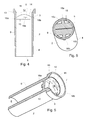
- Fig. 1 is a perspective view of a first embodiment of a self-sealing catheter valve 1 according to the present invention.
- the self-sealing catheter valve 1 has a flexible tubular part 2 with a proximal end part 3 that extends into a distal end part 4.
- a proximal valve part 5 is arranged inside the flexible tubular part 2 closer to the proximal end part 3 than to the distal end part 4, thereby enabling at least the distal end part 4 to pass below an injection port (not shown) of a catheter hub (not shown) to also serve as an injection valve 4 for the injection port.
- the distal end part 4 of the flexible tubular part 2 has a distal opening 6 through which infusion liquid can pass further into the catheter and the blood vessel, and via which distal opening 6 back flow of blood via the inserted catheter can enter the self-sealing catheter valve 1 to reach the proximal valve part 5.
- the proximal valve part 5 has a curved self-sealing flexible diaphragm 7 disposed inside the flexible tubular part 2.
- the proximal valve part 5 has a base perimeter 8 united with a circumferential wall 9 of the flexible tubular part 2 so that the curved self-sealing flexible diaphragm 7 protrudes towards the distal opening 6.
- the curved self-sealing flexible diaphragm 7 has a concave surface 11 facing towards the proximal opening 12, and a convex surface 10 facing towards the opposite distal opening 6 of the distal end part 4.
- the proximal end part 3 has a flange 13 terminating the proximal opening 12.
- the wall 14 of the curved self-sealing flexible diaphragm 7 of the proximal valve part 5 has a traverse slit 15 to allow passage of objects such as an inserted catheter or a male Luer (not shown), around which the traverse slit 15 conforms to seal tightly.
- a short annular skirt 20 is provided as a short length of circumferential wall of the proximal end part 3 and extends into the flange 13.
- An upright rib 16 is provided on the convex surface 10 of the wall 14 of the curved self-sealing flexible diaphragm 7.
- the upright rib 16 is arranged substantially perpendicular to the traverse slit 15 so as to divide the traverse slit 15 into two opposite upright flexible fins 16a,16b.
- the ends 17a,17b of the fins 16a,16b may be joined to the circumferential wall 9 of the flexible tubular part 2 or be free to flex in engagement with the circumferential wall 9 of the flexible tubular part 2.
- Two opposite protuberances 18a,18b or beads are provided aligned with the ends of the upright rib 16 on the exterior surface of the circumferential wall 9 of the flexible tubular part 2.
- Fig. 4 is a sectional axial view of fig. 1 taken in a plane through the traverse slit 15 to illustrate the curvature of the curved self-sealing flexible diaphragm 7.
- the base perimeter 8 is seen joined to the circumferential wall 9 of the flexible tubular part 2.
- Fig. 5 shows, similar to fig. 3 , the self-sealing catheter valve 1 intersected along a sectional line offset towards the circumferential wall 9 of the flexible tubular part 2 to illustrate that that the curved self-sealing flexible diaphragm 7 has a certain thickness, e.g. similar to the thickness of the circumferential wall 9 of the proximal end part 3 of the flexible tubular part 2, or slightly thicker, and that the upright fins 16a,16b merge into the curvature of the convex surface 10 of the curved self-sealing flexible diaphragm 7 in front of respective protuberances 18a,18b.
- a certain thickness e.g. similar to the thickness of the circumferential wall 9 of the proximal end part 3 of the flexible tubular part 2, or slightly thicker
- Fig. 6 shows a cross-section taken through the plane of the protuberances, and thus also through the top of the convex surface 10.
- Fig. 7 is a transparent view of the self-sealing catheter valve 1 to visualize the curvature of the curved self-sealing flexible diaphragm 7 and it's attachment inside the flexible tubular part 2.
- Fig. 7 otherwise corresponds to fig. 1 .
- Fig. 8 shows a second embodiment of a self-sealing catheter valve 19 seen from the proximal opening 12.
- the second embodiment 19 only differs from the first embodiment 1 in that the cross-section is oblong instead of substantially circular, so for like parts same reference numerals are used.
- the second embodiment of a self-sealing catheter valve 19 has a major diameter greater than the minor diameter.
- the mismatch between respective cross-sections forces the self-sealing catheter valve 19 to conform to circular tubular shape, thereby obtaining an inherent frictional engagement that, on the one hand prevents dislocation upon manipulation of the catheter, and on the other hand, since the major diameter of the oblong cross-section is greater than the internal diameter of the catheter hub, keeps and forces the edges of the traverse slit 15 tight together as a result of the pressure exerted on the protuberances and the upright rib by the catheter hub wall.
- Comparative catheter valves are shown in the followings figs. 9a, 9a, 9b, 10a, 10b, 10c , 11a, 11b . These catheter valves differ from the valves 1,19 of the present invention in having different proximal valve parts.
- the comparative catheter valve 20 seen in figs. 9a,9b,9c has a proximal valve part in form of a conventional cross-slit valve 21.
- the comparative catheter valve 22 seen in figs. 10a,10b,10c has a proximal valve part in form of a conventional multi-slotted dome valve 23.
- the comparative catheter valve 24 seen in figs. 11a, 11b has a proximal valve part in form of a conventional aortic valve shape.
- the comparative study reveals the superior sealing properties of the self-sealing catheter valve according to the present invention in that under all test conditions and in all test environments no leakage was seen.
- Preferred polymeric materials for manufacturing the self-sealing catheter valve according to the present invention include but is not limited to the liquid silicone rubbers of the SILPURAN® 6600 series obtainable from Wacker Chemie AG, Hans-Seidel-Platz 4, 81737 Ober, Germany, e.g. SILPURAN® 6600/50 A/B.
- the self-sealing catheter valve according to the present invention provides an efficient self-closing mechanism for a peripheral catheter assembly and constitutes an efficient barrier against potential contagious spread from the patient to the surrounding environment by blood born disease e.g. HIV, hepatitis and Ebola viruses.
- blood born disease e.g. HIV, hepatitis and Ebola viruses.
- the self-sealing catheter valve according to the present invention makes venipuncture must easier than hitherto known, providing the physician with a freedom to leave the patient after puncture. No blood flows unintended out of the peripheral catheter when no male part is inserted through the traverse slit and nothing enters inside the blood stream since the catheter hub always is either sealed or plugged.
- the self-sealing catheter valve according to the present inventions provides an optimum protection of personal from blood spillage and blood born contamination from the patient.
Landscapes
- Health & Medical Sciences (AREA)
- Heart & Thoracic Surgery (AREA)
- Life Sciences & Earth Sciences (AREA)
- Hematology (AREA)
- Anesthesiology (AREA)
- Biomedical Technology (AREA)
- Engineering & Computer Science (AREA)
- Pulmonology (AREA)
- Animal Behavior & Ethology (AREA)
- General Health & Medical Sciences (AREA)
- Public Health (AREA)
- Veterinary Medicine (AREA)
- Biophysics (AREA)
- Infusion, Injection, And Reservoir Apparatuses (AREA)
- Media Introduction/Drainage Providing Device (AREA)
Priority Applications (4)
| Application Number | Priority Date | Filing Date | Title |
|---|---|---|---|
| EP14196068.2A EP3028737A1 (fr) | 2014-12-03 | 2014-12-03 | Soupape de cathéter auto-obturante |
| PCT/EP2015/078570 WO2016087606A1 (fr) | 2014-12-03 | 2015-12-03 | Valve de cathéter auto-obturante |
| EP15807837.8A EP3226958B1 (fr) | 2014-12-03 | 2015-12-03 | Soupape de cathéter auto-obturante |
| US15/527,571 US10596351B2 (en) | 2014-12-03 | 2015-12-03 | Self-sealing catheter valve |
Applications Claiming Priority (1)
| Application Number | Priority Date | Filing Date | Title |
|---|---|---|---|
| EP14196068.2A EP3028737A1 (fr) | 2014-12-03 | 2014-12-03 | Soupape de cathéter auto-obturante |
Publications (1)
| Publication Number | Publication Date |
|---|---|
| EP3028737A1 true EP3028737A1 (fr) | 2016-06-08 |
Family
ID=52013879
Family Applications (2)
| Application Number | Title | Priority Date | Filing Date |
|---|---|---|---|
| EP14196068.2A Withdrawn EP3028737A1 (fr) | 2014-12-03 | 2014-12-03 | Soupape de cathéter auto-obturante |
| EP15807837.8A Active EP3226958B1 (fr) | 2014-12-03 | 2015-12-03 | Soupape de cathéter auto-obturante |
Family Applications After (1)
| Application Number | Title | Priority Date | Filing Date |
|---|---|---|---|
| EP15807837.8A Active EP3226958B1 (fr) | 2014-12-03 | 2015-12-03 | Soupape de cathéter auto-obturante |
Country Status (3)
| Country | Link |
|---|---|
| US (1) | US10596351B2 (fr) |
| EP (2) | EP3028737A1 (fr) |
| WO (1) | WO2016087606A1 (fr) |
Cited By (3)
| Publication number | Priority date | Publication date | Assignee | Title |
|---|---|---|---|---|
| WO2019038200A1 (fr) * | 2017-08-22 | 2019-02-28 | Roche Diabetes Care Gmbh | Septum à obturation automatique |
| WO2020033141A1 (fr) * | 2018-08-09 | 2020-02-13 | Becton, Dickinson And Company | Septum de contrôle sanguin et systèmes associés |
| WO2024008849A1 (fr) * | 2022-07-06 | 2024-01-11 | B. Braun Melsungen Ag | Dispositifs cathéters à valves et procédés associés |
Families Citing this family (22)
| Publication number | Priority date | Publication date | Assignee | Title |
|---|---|---|---|---|
| US8105288B2 (en) | 2008-01-14 | 2012-01-31 | I-V Access Technology, Inc. | Apparatus for peripheral vascular access |
| BR122019017170B1 (pt) * | 2015-08-18 | 2022-08-16 | B. Braun Melsungen Ag | Montagem de cateter |
| US10557552B2 (en) * | 2016-11-21 | 2020-02-11 | Cardiac Pacemakers, Inc. | Trough seal |
| AU2018316225B2 (en) * | 2017-08-10 | 2023-09-28 | St. Jude Medical, Cardiology Division, Inc. | Collapsible medical device for atrial sealing and trans-septal access |
| US11324939B2 (en) | 2017-08-31 | 2022-05-10 | I-V Access Technology, Inc. | Methods and devices for vascular access |
| US10406326B2 (en) | 2017-08-31 | 2019-09-10 | I-V Access Technology, Inc. | Methods and devices for vascular access |
| WO2019065943A1 (fr) | 2017-09-29 | 2019-04-04 | テルモ株式会社 | Ensemble cathéter et valve médicale |
| US20190308004A1 (en) * | 2018-04-04 | 2019-10-10 | Marius Saines | Low profile self-sealing access port |
| US10859540B2 (en) * | 2018-08-03 | 2020-12-08 | Chromatography Research Supplies, Inc. | Duckbill septum |
| WO2020127328A1 (fr) | 2018-12-17 | 2020-06-25 | B. Braun Melsungen Ag | Ensembles cathéter sur aiguille et leur procédé de fabrication |
| JP7387717B2 (ja) | 2019-03-28 | 2023-11-28 | テルモ株式会社 | カテーテル組立体 |
| JP7424680B2 (ja) | 2019-09-10 | 2024-01-30 | メドソース・インターナショナル・リミテッド・ライアビリティ・カンパニー | 静脈内カテーテルデバイス |
| JP7481429B2 (ja) * | 2020-03-09 | 2024-05-10 | テルモ株式会社 | 留置カテーテル、医療用弁及びカテーテル組立体 |
| WO2021194979A1 (fr) | 2020-03-23 | 2021-09-30 | I-V Access Technology, Inc. | Ensemble aiguille de cathéter à aiguille pouvant être enfermée |
| US12128205B1 (en) | 2020-07-08 | 2024-10-29 | Daniel Rinear | Hub assembly with a self-closing valve for use with a syringe |
| WO2022172281A1 (fr) | 2021-02-10 | 2022-08-18 | Neeraj Gupta | Canule intraveineuse |
| US12337123B2 (en) | 2021-05-06 | 2025-06-24 | Medsource Labs, Llc | Safety intravenous cannula |
| EP4284486B1 (fr) * | 2021-05-21 | 2025-04-30 | St. Jude Medical, Cardiology Division, Inc. | Joint de valve, et valves hémostatiques et unités de canule l'incorporant |
| JP7722052B2 (ja) * | 2021-08-27 | 2025-08-13 | 株式会社ジェイ・エム・エス | メスコネクタ |
| US12186497B2 (en) | 2022-01-14 | 2025-01-07 | Medsource International Llc | Intravenous cannula |
| US11607525B1 (en) | 2022-06-30 | 2023-03-21 | I-V Access Technology, Inc. | Methods and devices for vascular access |
| US20250195859A1 (en) * | 2023-12-18 | 2025-06-19 | W. L. Gore & Associates, Inc. | Flexible resealable septum |
Citations (10)
| Publication number | Priority date | Publication date | Assignee | Title |
|---|---|---|---|---|
| US3889675A (en) * | 1974-06-25 | 1975-06-17 | Stewart Research | Suction-irrigator |
| US4436519A (en) | 1981-05-28 | 1984-03-13 | Argon Medical Corp. | Removable hemostasis valve |
| EP0257880A1 (fr) * | 1986-08-18 | 1988-03-02 | Vernay Laboratories,Inc. | Clapet de retenue à utiliser avec une seringue |
| US5125903A (en) * | 1991-08-01 | 1992-06-30 | Medtronic, Inc. | Hemostasis valve |
| US5269763A (en) * | 1991-07-18 | 1993-12-14 | Vernay Laboratories, Inc. | Self-sealing cannula cap |
| US5456284A (en) * | 1993-05-10 | 1995-10-10 | Applied Medical Resources Corporation | Elastomeric valve assembly |
| US6039718A (en) * | 1998-01-20 | 2000-03-21 | Bracco Research Usa | Multiple use universal connector |
| WO2009016184A1 (fr) | 2007-08-01 | 2009-02-05 | Tradinco Ab | Ensemble de cathéter périphérique avec valve d'hémostase |
| WO2011073969A1 (fr) * | 2009-12-18 | 2011-06-23 | Vysera Biomedical Limited | Dispositif urologique |
| US20130090607A1 (en) * | 2011-10-06 | 2013-04-11 | Becton, Dickinson And Company | Intravenous catheter with duckbill valve |
Family Cites Families (4)
| Publication number | Priority date | Publication date | Assignee | Title |
|---|---|---|---|---|
| US5334159A (en) * | 1992-03-30 | 1994-08-02 | Symbiosis Corporation | Thoracentesis needle assembly utilizing check valve |
| US5533708A (en) * | 1992-06-04 | 1996-07-09 | Vernay Laboratories, Inc. | Medical coupling site valve body |
| WO2001012746A1 (fr) * | 1999-08-17 | 2001-02-22 | Porex Technologies Corporation | Matieres auto-obturantes et dispositifs comprenant ces dernieres |
| US20080154214A1 (en) * | 2006-12-22 | 2008-06-26 | Medrad, Inc. | Flow Based Pressure Isolation and Fluid Delivery System Including Flow Based Pressure Isolation |
-
2014
- 2014-12-03 EP EP14196068.2A patent/EP3028737A1/fr not_active Withdrawn
-
2015
- 2015-12-03 WO PCT/EP2015/078570 patent/WO2016087606A1/fr not_active Ceased
- 2015-12-03 EP EP15807837.8A patent/EP3226958B1/fr active Active
- 2015-12-03 US US15/527,571 patent/US10596351B2/en active Active
Patent Citations (11)
| Publication number | Priority date | Publication date | Assignee | Title |
|---|---|---|---|---|
| US3889675A (en) * | 1974-06-25 | 1975-06-17 | Stewart Research | Suction-irrigator |
| US4436519A (en) | 1981-05-28 | 1984-03-13 | Argon Medical Corp. | Removable hemostasis valve |
| US4436519B1 (fr) | 1981-05-28 | 1989-04-04 | ||
| EP0257880A1 (fr) * | 1986-08-18 | 1988-03-02 | Vernay Laboratories,Inc. | Clapet de retenue à utiliser avec une seringue |
| US5269763A (en) * | 1991-07-18 | 1993-12-14 | Vernay Laboratories, Inc. | Self-sealing cannula cap |
| US5125903A (en) * | 1991-08-01 | 1992-06-30 | Medtronic, Inc. | Hemostasis valve |
| US5456284A (en) * | 1993-05-10 | 1995-10-10 | Applied Medical Resources Corporation | Elastomeric valve assembly |
| US6039718A (en) * | 1998-01-20 | 2000-03-21 | Bracco Research Usa | Multiple use universal connector |
| WO2009016184A1 (fr) | 2007-08-01 | 2009-02-05 | Tradinco Ab | Ensemble de cathéter périphérique avec valve d'hémostase |
| WO2011073969A1 (fr) * | 2009-12-18 | 2011-06-23 | Vysera Biomedical Limited | Dispositif urologique |
| US20130090607A1 (en) * | 2011-10-06 | 2013-04-11 | Becton, Dickinson And Company | Intravenous catheter with duckbill valve |
Cited By (7)
| Publication number | Priority date | Publication date | Assignee | Title |
|---|---|---|---|---|
| WO2019038200A1 (fr) * | 2017-08-22 | 2019-02-28 | Roche Diabetes Care Gmbh | Septum à obturation automatique |
| US12151083B2 (en) | 2017-08-22 | 2024-11-26 | Roche Diabetes Care, Inc. | Self-sealing septum |
| WO2020033141A1 (fr) * | 2018-08-09 | 2020-02-13 | Becton, Dickinson And Company | Septum de contrôle sanguin et systèmes associés |
| KR20210043573A (ko) * | 2018-08-09 | 2021-04-21 | 백톤 디킨슨 앤드 컴퍼니 | 혈액 제어 격막 및 관련 시스템 |
| US11324919B2 (en) | 2018-08-09 | 2022-05-10 | Becton, Dickinson And Company | Blood control septum and related systems |
| KR102779734B1 (ko) | 2018-08-09 | 2025-03-12 | 백톤 디킨슨 앤드 컴퍼니 | 혈액 제어 격막 및 관련 시스템 |
| WO2024008849A1 (fr) * | 2022-07-06 | 2024-01-11 | B. Braun Melsungen Ag | Dispositifs cathéters à valves et procédés associés |
Also Published As
| Publication number | Publication date |
|---|---|
| EP3226958B1 (fr) | 2018-10-10 |
| US20170326341A1 (en) | 2017-11-16 |
| EP3226958A1 (fr) | 2017-10-11 |
| WO2016087606A1 (fr) | 2016-06-09 |
| US10596351B2 (en) | 2020-03-24 |
Similar Documents
| Publication | Publication Date | Title |
|---|---|---|
| EP3028737A1 (fr) | Soupape de cathéter auto-obturante | |
| JP7247294B2 (ja) | 閉鎖系カテーテル | |
| US20240009406A1 (en) | Hemostasis valve-equipped indwelling needle and indwelling needle assembly | |
| AU2005284825C1 (en) | Self-sealing male Luer connector with molded elastomeric tip | |
| EP2445572B1 (fr) | Valve médicale à étanchéité améliorée à la contre-pression | |
| ES2429563T3 (es) | Conector de válvula de fluido | |
| CN105148376B (zh) | 具有密封件的导管组件 | |
| JP5086811B2 (ja) | 折りたたみ可能な本体を備えた自己封止式雄コネクタ装置 | |
| US20170319822A1 (en) | Intravenous Catheter Assembly | |
| EP2111888A2 (fr) | Raccord sans aiguille pour accès luer | |
| US20100249725A1 (en) | Medical Valve with Multiple Variable Volume Regions | |
| JP2021515687A (ja) | 静脈内カテーテル組立品 | |
| AU2006307253A1 (en) | Indwelling needle assembly | |
| US20250152918A1 (en) | Closed system catheter | |
| CN220110187U (zh) | 外周静脉内导管组件 | |
| KR101728963B1 (ko) | 의료용 카테터 |
Legal Events
| Date | Code | Title | Description |
|---|---|---|---|
| PUAI | Public reference made under article 153(3) epc to a published international application that has entered the european phase |
Free format text: ORIGINAL CODE: 0009012 |
|
| AK | Designated contracting states |
Kind code of ref document: A1 Designated state(s): AL AT BE BG CH CY CZ DE DK EE ES FI FR GB GR HR HU IE IS IT LI LT LU LV MC MK MT NL NO PL PT RO RS SE SI SK SM TR |
|
| AX | Request for extension of the european patent |
Extension state: BA ME |
|
| 17P | Request for examination filed |
Effective date: 20161206 |
|
| RBV | Designated contracting states (corrected) |
Designated state(s): AL AT BE BG CH CY CZ DE DK EE ES FI FR GB GR HR HU IE IS IT LI LT LU LV MC MK MT NL NO PL PT RO RS SE SI SK SM TR |
|
| 17Q | First examination report despatched |
Effective date: 20171030 |
|
| STAA | Information on the status of an ep patent application or granted ep patent |
Free format text: STATUS: THE APPLICATION IS DEEMED TO BE WITHDRAWN |
|
| 18D | Application deemed to be withdrawn |
Effective date: 20180817 |