EP3028896A1 - Dispositif d'éclairage pour un véhicule automobile, véhicule automobile comprenant un dispositif d'éclairage et procédé de fonctionnement d'un dispositif d'éclairage - Google Patents
Dispositif d'éclairage pour un véhicule automobile, véhicule automobile comprenant un dispositif d'éclairage et procédé de fonctionnement d'un dispositif d'éclairage Download PDFInfo
- Publication number
- EP3028896A1 EP3028896A1 EP15003338.9A EP15003338A EP3028896A1 EP 3028896 A1 EP3028896 A1 EP 3028896A1 EP 15003338 A EP15003338 A EP 15003338A EP 3028896 A1 EP3028896 A1 EP 3028896A1
- Authority
- EP
- European Patent Office
- Prior art keywords
- optical component
- light
- motor vehicle
- illumination
- lighting device
- Prior art date
- Legal status (The legal status is an assumption and is not a legal conclusion. Google has not performed a legal analysis and makes no representation as to the accuracy of the status listed.)
- Granted
Links
Images


Classifications
-
- F—MECHANICAL ENGINEERING; LIGHTING; HEATING; WEAPONS; BLASTING
- F21—LIGHTING
- F21S—NON-PORTABLE LIGHTING DEVICES; SYSTEMS THEREOF; VEHICLE LIGHTING DEVICES SPECIALLY ADAPTED FOR VEHICLE EXTERIORS
- F21S41/00—Illuminating devices specially adapted for vehicle exteriors, e.g. headlamps
- F21S41/60—Illuminating devices specially adapted for vehicle exteriors, e.g. headlamps characterised by a variable light distribution
- F21S41/63—Illuminating devices specially adapted for vehicle exteriors, e.g. headlamps characterised by a variable light distribution by acting on refractors, filters or transparent cover plates
- F21S41/635—Illuminating devices specially adapted for vehicle exteriors, e.g. headlamps characterised by a variable light distribution by acting on refractors, filters or transparent cover plates by moving refractors, filters or transparent cover plates
-
- B—PERFORMING OPERATIONS; TRANSPORTING
- B60—VEHICLES IN GENERAL
- B60Q—ARRANGEMENT OF SIGNALLING OR LIGHTING DEVICES, THE MOUNTING OR SUPPORTING THEREOF OR CIRCUITS THEREFOR, FOR VEHICLES IN GENERAL
- B60Q1/00—Arrangement of optical signalling or lighting devices, the mounting or supporting thereof or circuits therefor
- B60Q1/02—Arrangement of optical signalling or lighting devices, the mounting or supporting thereof or circuits therefor the devices being primarily intended to illuminate the way ahead or to illuminate other areas of way or environments
- B60Q1/04—Arrangement of optical signalling or lighting devices, the mounting or supporting thereof or circuits therefor the devices being primarily intended to illuminate the way ahead or to illuminate other areas of way or environments the devices being headlights
- B60Q1/06—Arrangement of optical signalling or lighting devices, the mounting or supporting thereof or circuits therefor the devices being primarily intended to illuminate the way ahead or to illuminate other areas of way or environments the devices being headlights adjustable, e.g. remotely-controlled from inside vehicle
- B60Q1/08—Arrangement of optical signalling or lighting devices, the mounting or supporting thereof or circuits therefor the devices being primarily intended to illuminate the way ahead or to illuminate other areas of way or environments the devices being headlights adjustable, e.g. remotely-controlled from inside vehicle automatically
- B60Q1/085—Arrangement of optical signalling or lighting devices, the mounting or supporting thereof or circuits therefor the devices being primarily intended to illuminate the way ahead or to illuminate other areas of way or environments the devices being headlights adjustable, e.g. remotely-controlled from inside vehicle automatically due to special conditions, e.g. adverse weather, type of road, badly illuminated road signs or potential dangers
-
- B—PERFORMING OPERATIONS; TRANSPORTING
- B60—VEHICLES IN GENERAL
- B60Q—ARRANGEMENT OF SIGNALLING OR LIGHTING DEVICES, THE MOUNTING OR SUPPORTING THEREOF OR CIRCUITS THEREFOR, FOR VEHICLES IN GENERAL
- B60Q1/00—Arrangement of optical signalling or lighting devices, the mounting or supporting thereof or circuits therefor
- B60Q1/02—Arrangement of optical signalling or lighting devices, the mounting or supporting thereof or circuits therefor the devices being primarily intended to illuminate the way ahead or to illuminate other areas of way or environments
- B60Q1/04—Arrangement of optical signalling or lighting devices, the mounting or supporting thereof or circuits therefor the devices being primarily intended to illuminate the way ahead or to illuminate other areas of way or environments the devices being headlights
- B60Q1/06—Arrangement of optical signalling or lighting devices, the mounting or supporting thereof or circuits therefor the devices being primarily intended to illuminate the way ahead or to illuminate other areas of way or environments the devices being headlights adjustable, e.g. remotely-controlled from inside vehicle
- B60Q1/08—Arrangement of optical signalling or lighting devices, the mounting or supporting thereof or circuits therefor the devices being primarily intended to illuminate the way ahead or to illuminate other areas of way or environments the devices being headlights adjustable, e.g. remotely-controlled from inside vehicle automatically
- B60Q1/12—Arrangement of optical signalling or lighting devices, the mounting or supporting thereof or circuits therefor the devices being primarily intended to illuminate the way ahead or to illuminate other areas of way or environments the devices being headlights adjustable, e.g. remotely-controlled from inside vehicle automatically due to steering position
-
- F—MECHANICAL ENGINEERING; LIGHTING; HEATING; WEAPONS; BLASTING
- F21—LIGHTING
- F21S—NON-PORTABLE LIGHTING DEVICES; SYSTEMS THEREOF; VEHICLE LIGHTING DEVICES SPECIALLY ADAPTED FOR VEHICLE EXTERIORS
- F21S41/00—Illuminating devices specially adapted for vehicle exteriors, e.g. headlamps
- F21S41/10—Illuminating devices specially adapted for vehicle exteriors, e.g. headlamps characterised by the light source
- F21S41/14—Illuminating devices specially adapted for vehicle exteriors, e.g. headlamps characterised by the light source characterised by the type of light source
- F21S41/141—Light emitting diodes [LED]
- F21S41/143—Light emitting diodes [LED] the main emission direction of the LED being parallel to the optical axis of the illuminating device
-
- F—MECHANICAL ENGINEERING; LIGHTING; HEATING; WEAPONS; BLASTING
- F21—LIGHTING
- F21S—NON-PORTABLE LIGHTING DEVICES; SYSTEMS THEREOF; VEHICLE LIGHTING DEVICES SPECIALLY ADAPTED FOR VEHICLE EXTERIORS
- F21S41/00—Illuminating devices specially adapted for vehicle exteriors, e.g. headlamps
- F21S41/10—Illuminating devices specially adapted for vehicle exteriors, e.g. headlamps characterised by the light source
- F21S41/14—Illuminating devices specially adapted for vehicle exteriors, e.g. headlamps characterised by the light source characterised by the type of light source
- F21S41/141—Light emitting diodes [LED]
- F21S41/151—Light emitting diodes [LED] arranged in one or more lines
-
- F—MECHANICAL ENGINEERING; LIGHTING; HEATING; WEAPONS; BLASTING
- F21—LIGHTING
- F21S—NON-PORTABLE LIGHTING DEVICES; SYSTEMS THEREOF; VEHICLE LIGHTING DEVICES SPECIALLY ADAPTED FOR VEHICLE EXTERIORS
- F21S41/00—Illuminating devices specially adapted for vehicle exteriors, e.g. headlamps
- F21S41/10—Illuminating devices specially adapted for vehicle exteriors, e.g. headlamps characterised by the light source
- F21S41/14—Illuminating devices specially adapted for vehicle exteriors, e.g. headlamps characterised by the light source characterised by the type of light source
- F21S41/16—Laser light sources
-
- B—PERFORMING OPERATIONS; TRANSPORTING
- B60—VEHICLES IN GENERAL
- B60Q—ARRANGEMENT OF SIGNALLING OR LIGHTING DEVICES, THE MOUNTING OR SUPPORTING THEREOF OR CIRCUITS THEREFOR, FOR VEHICLES IN GENERAL
- B60Q2300/00—Indexing codes for automatically adjustable headlamps or automatically dimmable headlamps
- B60Q2300/05—Special features for controlling or switching of the light beam
- B60Q2300/056—Special anti-blinding beams, e.g. a standard beam is chopped or moved in order not to blind
Definitions
- the invention relates to a lighting device for a motor vehicle and a method for operating a lighting device specified in the preambles of claims 1 and 8 kind. Furthermore, the invention relates to a motor vehicle with a lighting device specified in claim 6.
- adaptive headlamps are well known in the art.
- their illumination intensity and illumination direction can be adapted to a driving state of the relevant motor vehicle and / or to a traffic situation of the motor vehicle, so that a roadway is optimally illuminated.
- a light module which has a reflector and a corresponding light source is pivoted by means of a movable frame. The pivoting of the light module takes place for example via a stepper motor.
- objects can be left out, deliberately illuminated or illuminated adaptively by shifting a light centroid.
- the first-mentioned variant makes it necessary that relatively large masses must be moved, for example, the above-mentioned reflector, a lens, corresponding bulbs, support frames and the like. This requires a great deal of mechanical effort, particularly strong stepper motors, sometimes results in relatively large gaps, In addition, a movement of the corresponding photograph always appears sluggish.
- large optical systems are unavoidable due to the necessity of multiple segments, which require a correspondingly large space.
- the DE 103 21 564 A1 shows a motor vehicle headlamp, wherein a curvature of a light exit surface of the motor vehicle headlight is changed, as a result, a beam path of an LED is changed by the light exit surface. This achieves defocusing of the light emitted by the LED.
- the DE 197 37 653 A1 shows a mirror surface having a plurality of micromirrors which is illuminated by a xenon light source. By switching, ie by switching on or off, the micromirror, the light distribution can be changed. Different light functions such as a high beam, a low beam, a fog light and the like can be achieved with only one light source.
- the DE 10 2008 022 7965 A1 shows a vehicle headlamp, which has a laser as the light source.
- the laser is aimed at a light modulator.
- the light modulator has at least one mirror, which can be pivoted at least about a mirror axis. As a result, the emission characteristic of the light source can be changed.
- the DE 10 2012 224 345 A1 shows a vehicle headlamp, which includes a semiconductor light source and a position adjustable by means of a piezoelectric lens. As a result, a light emission pattern of the vehicle headlight can be varied without the need to adjust the semiconductor light source and a cooling device connected thereto.
- the DE 100 05 795 A1 shows a headlight having a lens and a light emitter.
- the lens can be moved by means of an actuator, as a result of which a cone of light is pivoted.
- the DE 20 2007 018 181 U1 shows a headlamp with at least one light source.
- the headlamp includes a lens which is rotatably mounted about an approximately vertical axis. As a result, a light distribution on the roadway can be pivoted horizontally.
- the DE 196 25 923 A1 shows a vehicle headlamp with a light source and a lens.
- the lens can be moved vertically and horizontally to adjust respective angles of incidence of a luminous flux distribution.
- the DE 10 2009 035 743 A1 shows a light module for a motor vehicle headlight.
- the light module comprises a light source and a lens.
- the entire light module can be pivoted about a vertical axis of rotation.
- the DE 10 2007 049 361 A1 shows a vehicle headlamp with a light source and a lens which is pivotable about a substantially vertical axis to realize a cornering light function.
- the US 2010/0061090 A1 shows a lighting system with multiple light sources and multiple lenses.
- the lenses are translationally displaceable, whereby respective light beams can be pivoted.
- the DE 10 2013 003 959 A1 shows a method for operating a headlamp system of a motor vehicle. As soon as a movement of a person in the direction of travel in front of the motor vehicle is detected, at least one headlight of the headlight system is pivoted about a vertical axis.
- the EP 2 128 521 A shows a pivotable vehicle headlight.
- the vehicle headlight can be pivoted so that a beam of light is directed to a pedestrian.
- the illumination device according to the invention for a motor vehicle comprises at least one adaptive illumination unit which has an immovably arranged illumination source and at least one optical component arranged at least partially in a beam path of the illumination source and an adjustment device which is designed to move the optical component.
- the lighting device according to the invention is characterized in that the adjusting device comprises a micromechanical actuator, wherein the optical component is arranged and designed such that from a movement of the optical component by means of the micromechanical actuator, a pivoting of a producible by means of the illumination source in cooperation with the optical component Light cone results.
- the optical component is according to the invention a lens.
- the optical component can also be an attachment optics or another imaging system.
- a movement of the optical component causes a change in alignment and / or positioning of the optical component with respect to the illumination source.
- a refraction or diffraction of at least a part of the beam path of the illumination source passing through the optical component is correspondingly changed, which results in the pivoting of the light cone.
- the optical component is preferably arranged and configured such that the dimensions of the light cone change as little as possible when the light cone is pivoted, ie the light cone as such remains essentially unchanged with respect to its shape and only its orientation can be changed.
- the execution of a movable light cone is thus in other words via a micromechanics in the form of the micromechanical actuator having adjusting.
- the illumination source is static and does not need to be moved.
- the optical component arranged in the emission direction of the illumination unit in front of the illumination unit or else further optical components can be moved in such a way that the image of the light cone can be changed adaptively. As a result, no large masses need to be moved and there are no large optical Components required to provide an adaptive cone of light.
- the optical component is mounted pivotably about an axis and the micromechanical actuator is designed to pivot the optical component about the axis.
- the light cone can be pivoted about the vehicle's vertical axis and / or about the vehicle transverse axis when the illumination device is arranged in the motor vehicle as intended.
- a translational mobility of the optical component relative to the immovable, that is rigidly arranged, optical component is also possible. As a result, a focusing or defocusing of the illumination source can be achieved.
- the micromechanical actuator is a piezoelectric actuator.
- the micromechanical actuator can also be an electrostatic actuator, for example in the form of an electrostatic torsion structure.
- the micromechanical actuator can also comprise a shape memory alloy or an electro-thermo-mechanical converter by means of which the optical component can be moved.
- all actuators can serve as the micromechanical actuator of the adjusting device, which find application in microsystem technology.
- the micromechanical actuator thus has a very small design, so that the entire lighting device can be made compact.
- a further advantageous embodiment of the invention provides that the illumination source is a laser.
- the laser By the laser, a substantially point-shaped illumination source can be provided, which has a very small diameter.
- very small deflections of the optical component are sufficient in order to bring about relatively large deflections or pivoting movements of the light cone.
- Smallest movements of the optical component of, for example, 0.1 mm are sufficient to pivot the cone of light by about 5 °.
- the actuator and the optical system can be designed accordingly.
- a punctiform illumination source a laser is particularly advantageous, since it has a very high luminance.
- a further advantageous embodiment of the invention provides that the illumination device is designed to provide a basic light distribution with a low beam function and / or a high beam function, wherein the light cone of the basic light distribution that can be generated by the illumination source in cooperation with the optical component is at least partially overlayable.
- the low-beam and / or high-beam function can be implemented, for example, by means of xenon headlamps, LED headlights, a laser light based headlight or halogen headlights.
- the use of an LED headlight to provide the basic light distribution, when using a laser as the illumination source, has the advantage that the light colors in LED headlights and lasers can be made relatively similar.
- the light cone which can be generated by means of the illumination source in cooperation with the optical component can serve, for example, as supplementary illumination for the high beam function, but can also serve as supplementary illumination for the low beam function.
- the light cone can be superimposed on a basic light distribution, whereby, for example, an illuminance in a central region of the basic light distribution can be increased.
- the superimposition of the light cone can also serve for the visual representation of individual light sources, in particular for the representation or better experience of superimposed additional light functions.
- a harmonization of further light distributions such as, for example, a partial high-beam, can be achieved by superposition of the light cone.
- the movable light beam itself can also serve, for example, as a partial high-beam light with a vertical light-dark boundary. For example, this may partially increase the illuminance, in particular adjacent to objects recessed by the basic light distribution. If the movable light beam itself is used as a partial high-beam light, this increases the areas of use of the partial high-beam light, since the movable light cone is particularly easy to pivot and thus adjustable to different driving situations. Furthermore, the movable cone of light in the form of a partial high-beam light can also contribute to the visual clarification and experience of the partial high beam.
- the light cone which can be generated by means of the illumination source in cooperation with the optical component for the adaptive illumination of a road course for example in curves or as another topology compensation.
- the adaptive illumination of the road course is preferably carried out in the form of a partial high-beam, whereby the usability and visibility of this partial high-beam also increased and the visual clarity and experience of the partial high-beam is enhanced.
- the motor vehicle according to the invention comprises the lighting device according to the invention or an advantageous embodiment of the lighting device according to the invention.
- the lighting device has two of the lighting units, wherein one of the lighting units is arranged in a left headlight module of the motor vehicle and one of the lighting units in a right headlight module of the motor vehicle.
- an optical component which is arranged at least partially in a beam path of an illumination source of at least one adaptive lighting unit and designed as a lens, is moved by means of an adjusting device.
- the adjusting device comprises a micromechanical actuator by means of which the optical component is moved such that a light cone generated in cooperation with the optical component is pivoted by means of the illumination source, the optical component being mounted pivotably about an axis is and the optical component is pivoted about the axis by means of the micromechanical actuator.
- Advantageous embodiments of the lighting device according to the invention are to be regarded as advantageous embodiments of the method according to the invention, wherein the lighting device has in particular means for performing the method steps.
- the micromechanical actuator is actuated for moving the optical component as a function of a detected traffic situation of the motor vehicle.
- the optical component can be moved adaptively by means of the micromechanical actuator as a function of a detected traffic situation, so that the light cone which can be generated by the illumination source in cooperation with the optical component can be pivoted as a function of a respectively detected traffic situation of the motor vehicle.
- a vehicle situation for example a loading state and a resulting pivoting or inclination of the motor vehicle about its vehicle transverse axis, are taken into account. As a result, optimum illumination of a roadway in any vehicle condition and in any traffic situation can be ensured.
- the vehicle includes appropriately designed sensors, which are designed to permanently detect the current driving state, such as cornering, turning, loading conditions of the motor vehicle and the current traffic situation, such as darkness, heavy rain, other road users and the like.
- An appropriately designed control unit evaluates the individual information and adjusts the illumination of the road by a corresponding control of the micromechanical actuator, which in turn actuates or moves the optical component in accordance with the control signals.
- a motor vehicle 10 with a lighting device 12 is in a schematic plan view in Fig. 1 shown.
- the lighting device 12 comprises a left headlight module 14 and a right headlight module 16.
- the headlight modules 14, 16 each include an adaptive lighting unit 18, 20.
- the headlight modules 14, 16 each comprise further lighting units 22, which are adapted to a basic light distribution with a To provide low beam function and a high beam function.
- FIG. 2 For example, one of the two adaptive lighting units 18 is shown in a schematic perspective view.
- the lighting unit 20 (not illustrated here), which is arranged in the right-hand headlight module 16, has essentially the same structure as the adaptive lighting unit 18 shown schematically here.
- the adaptive illumination unit 18 comprises an immovably arranged illumination source 24, which in the present case is designed as a laser. Furthermore, the illumination unit 18 has an optical component 28 arranged in a beam path 26 of the illumination source 24 and also a light source Adjustment device 30 which is adapted to move the optical component 28.
- the adjusting device 30 has in the present case a piezoelectric actuator, wherein the optical component 28 is arranged and designed such that from a movement of the optical component 28 by means of the piezoelectric actuator 30, a pivoting of one by means of the illumination source 24 in cooperation with the optical component 28th producible light cone 32 results.
- the adjusting device 30 may include, for example, an electrostatic actuator, a shape memory alloy or an electro-thermo-mechanical converter, by means of which the optical component 28 is movable.
- an electrostatic actuator for example, a shape memory alloy or an electro-thermo-mechanical converter, by means of which the optical component 28 is movable.
- all actuators can be used as a micromechanical actuator, which find application in microsystems technology.
- the optical component 28 is a lens by means of which the beam path 26 of the illumination source 24 is differently refracted or diffracted relative to the illumination source 24, depending on the orientation and / or positioning of the optical component 28.
- the optical component 28 is pivotable about an axis 34 or rotatable, the piezoelectric actuator of the adjusting device 30 being designed to pivot or rotate the optical component 28 about the axis 34.
- the piezoelectric actuator can be designed, for example, in the form of a microbending element, with a piezoelectric material being applied, for example, to a piezoelectrically inactive material. Both the piezoelectric material and the piezoelectrically inactive material are clamped in the form of a beam clamping. If an electrical voltage is applied or applied to the piezoelectric material, a change in length of the piezoelectric material caused by a transverse effect is converted by the rigid inactive material into a curvature of the entire arrangement. As a result, a simple pivoting of the optical component 28 about the axis 34 can take place. Essentially, however, all micromechanical actuators that are used in microsystems technology can be used for the adjusting device 30 are used for pivoting the optical component 28.
- the lighting unit 18 is arranged such that the light cone 32 can be pivoted about the vehicle vertical axis z.
- the light cone 32 can be pivoted from the perspective of a vehicle occupant to the left and right.
- the optical component 28 it is also possible for the optical component 28 to be arranged and configured in such a way that the light cone 32 can be pivoted about the vehicle transverse axis y when the adaptive illumination unit 18 or the entire illumination device 12 in the motor vehicle 10 is arranged as intended. In other words, the light cone 32 can thus be pivoted up and down from the perspective of a vehicle occupant.
- the illumination unit 18 may also be designed such that a translational mobility of the optical component 28 relative to the immovable, ie rigidly arranged, optical component 28 is possible.
- a focusing or defocusing of the illumination source 24 can also be achieved.
- the headlight modules 14, 16 further comprise lighting units 22, which are adapted to provide a basic light distribution with a low beam function and a high beam function.
- the further lighting units 22 can be implemented, for example, as xenon headlamps, LED headlamps, headlights based on laser light or else as halogen headlamps, by means of which the dipped beam function and the high beam function can be provided.
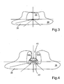
- a first possible embodiment of a superimposed by the light cone 32 basic light distribution 36 is shown schematically.
- the basic light distribution 36 which has a dipped beam and / or a high beam, is generated or provided by means of the illumination units 22.
- the means of the two adaptive lighting units 18, 22nd generated light cone 32 is superimposed on the basic light distribution 36, which contributes to increasing the illuminance in a central region of the basic light distribution 36.
- a roadway 38 in a long-range area can be illuminated more intensively.
- Fig. 4 is a further possible application of the adaptive lighting units 18, 20 shown schematically.
- the basic light distribution 36 is provided or generated by means of the illumination units 22.
- the basic light distribution 36 has a recess 40 exactly where a preceding vehicle 42 is located.
- the two adaptive illumination units 18, 20 are controlled in such a way that the two light cones 32a and 32b result.
- the light cones 32a, 32b are thus used as a kind of partial high beam with a vertical light-dark boundary. This serves, in particular, to increase the illuminance adjacent to the preceding vehicle 42 recessed by the basic light distribution 36.
- Fig. 5 is another application for the adaptive lighting units 18, 20 shown schematically.
- the basic light distribution 36 is provided by means of the illumination units 22.
- the movable light cone 32 of the lighting units 18, 22 serve here for adaptive illumination of the roadway 38 in curves as topology compensation.
- the two adaptive illumination units 18, 22 are used in the present case as a kind of partial high-beam light, by means of which in particular curves can be illuminated particularly well.
Landscapes
- Engineering & Computer Science (AREA)
- General Engineering & Computer Science (AREA)
- Physics & Mathematics (AREA)
- Optics & Photonics (AREA)
- Microelectronics & Electronic Packaging (AREA)
- Mechanical Engineering (AREA)
- Non-Portable Lighting Devices Or Systems Thereof (AREA)
- Lighting Device Outwards From Vehicle And Optical Signal (AREA)
Applications Claiming Priority (1)
| Application Number | Priority Date | Filing Date | Title |
|---|---|---|---|
| DE102014017978.8A DE102014017978A1 (de) | 2014-12-04 | 2014-12-04 | Beleuchtungsvorrichtung für ein Kraftfahrzeug, Kraftfahrzeug mit einer Beleuchtungsvorrichtung und Verfahren zum Betreiben einer Beleuchtungsvorrichtung |
Publications (2)
| Publication Number | Publication Date |
|---|---|
| EP3028896A1 true EP3028896A1 (fr) | 2016-06-08 |
| EP3028896B1 EP3028896B1 (fr) | 2020-09-16 |
Family
ID=54705346
Family Applications (1)
| Application Number | Title | Priority Date | Filing Date |
|---|---|---|---|
| EP15003338.9A Active EP3028896B1 (fr) | 2014-12-04 | 2015-11-21 | Dispositif d'éclairage pour un véhicule automobile, véhicule automobile comprenant un dispositif d'éclairage et procédé de fonctionnement d'un dispositif d'éclairage |
Country Status (2)
| Country | Link |
|---|---|
| EP (1) | EP3028896B1 (fr) |
| DE (1) | DE102014017978A1 (fr) |
Families Citing this family (1)
| Publication number | Priority date | Publication date | Assignee | Title |
|---|---|---|---|---|
| DE102017214407A1 (de) * | 2017-08-18 | 2019-02-21 | Osram Gmbh | Beleuchtungssystem und scheinwerfer |
Citations (21)
| Publication number | Priority date | Publication date | Assignee | Title |
|---|---|---|---|---|
| DE19625923A1 (de) | 1996-06-28 | 1998-01-08 | Hella Kg Hueck & Co | Scheinwerfer für Fahrzeuge |
| DE19737653A1 (de) | 1997-08-29 | 1999-03-04 | Patent Treuhand Ges Fuer Elektrische Gluehlampen Mbh | Beleuchtungseinrichtung für Fahrzeuge und Betriebsverfahren für eine derartige Beleuchtungseinrichtung |
| DE10005795A1 (de) | 2000-02-10 | 2001-08-23 | Inst Mikrotechnik Mainz Gmbh | Steuerbarer Scheinwerfer |
| DE10321564A1 (de) | 2003-05-14 | 2004-12-16 | Audi Ag | Kraftfahrzeugscheinwerfer |
| JP2006179246A (ja) * | 2004-12-21 | 2006-07-06 | Ichikoh Ind Ltd | 車両用前照灯ユニット |
| JP2008010265A (ja) * | 2006-06-28 | 2008-01-17 | Ichikoh Ind Ltd | 車両用前照灯 |
| DE102007049361A1 (de) | 2006-10-23 | 2008-05-08 | Zizala Lichtsysteme Gmbh | Optikelement für einen Fahrzeugscheinwerfer |
| DE202007018181U1 (de) | 2007-12-31 | 2008-05-08 | Automotive Lighting Reutlingen Gmbh | Projektionsmodul mit dynamischer Kurvenlichtfunktion |
| JP2009206015A (ja) * | 2008-02-29 | 2009-09-10 | Nissan Motor Co Ltd | 車両用前照灯装置 |
| DE102008022795A1 (de) | 2008-05-08 | 2009-11-12 | Osram Opto Semiconductors Gmbh | Kfz-Scheinwerfer |
| EP2128521A1 (fr) | 2008-05-27 | 2009-12-02 | Valeo Vision | Projecteur de véhicule automobile susceptible d'émettre un faisceau lumineux orientable. |
| US20100061090A1 (en) | 2005-07-13 | 2010-03-11 | Koninklijke Philips Electronics, N.V. | Illumination system |
| DE102009035743A1 (de) | 2009-08-01 | 2011-02-17 | Automotive Lighting Reutlingen Gmbh | Lichtmodul für einen Kraftfahrzeugscheinwerfer |
| US20120026746A1 (en) * | 2009-01-05 | 2012-02-02 | Koninklijke Philips Electronics N.V. | Lighting assembly and automotive headlamp arrangement |
| EP2434204A2 (fr) * | 2010-09-27 | 2012-03-28 | Audi AG | Phare pour un véhicule automobile et véhicule automobile |
| WO2012098142A1 (fr) * | 2011-01-20 | 2012-07-26 | Valeo Vision | Module de projection d'un faisceau |
| DE102012205435A1 (de) * | 2012-04-03 | 2013-10-10 | Bayerische Motoren Werke Aktiengesellschaft | Beleuchtungsvorrichtung für ein Kraftfahrzeug |
| DE102013003959A1 (de) | 2012-06-26 | 2014-01-02 | Volkswagen Ag | Verfahren zum Betreiben eines Scheinwerfersystems in einem Fahrzeug und dazugehöriges Scheinwerfersystem |
| GB2504330A (en) * | 2012-07-26 | 2014-01-29 | Sharp Kk | Headlight system incorporating adaptive beam function |
| EP2719942A1 (fr) * | 2011-06-08 | 2014-04-16 | Koito Manufacturing Co., Ltd. | Unité optique |
| DE102012224345A1 (de) | 2012-12-21 | 2014-06-26 | Osram Gmbh | Fahrzeug-Leuchtvorrichtung |
-
2014
- 2014-12-04 DE DE102014017978.8A patent/DE102014017978A1/de not_active Ceased
-
2015
- 2015-11-21 EP EP15003338.9A patent/EP3028896B1/fr active Active
Patent Citations (21)
| Publication number | Priority date | Publication date | Assignee | Title |
|---|---|---|---|---|
| DE19625923A1 (de) | 1996-06-28 | 1998-01-08 | Hella Kg Hueck & Co | Scheinwerfer für Fahrzeuge |
| DE19737653A1 (de) | 1997-08-29 | 1999-03-04 | Patent Treuhand Ges Fuer Elektrische Gluehlampen Mbh | Beleuchtungseinrichtung für Fahrzeuge und Betriebsverfahren für eine derartige Beleuchtungseinrichtung |
| DE10005795A1 (de) | 2000-02-10 | 2001-08-23 | Inst Mikrotechnik Mainz Gmbh | Steuerbarer Scheinwerfer |
| DE10321564A1 (de) | 2003-05-14 | 2004-12-16 | Audi Ag | Kraftfahrzeugscheinwerfer |
| JP2006179246A (ja) * | 2004-12-21 | 2006-07-06 | Ichikoh Ind Ltd | 車両用前照灯ユニット |
| US20100061090A1 (en) | 2005-07-13 | 2010-03-11 | Koninklijke Philips Electronics, N.V. | Illumination system |
| JP2008010265A (ja) * | 2006-06-28 | 2008-01-17 | Ichikoh Ind Ltd | 車両用前照灯 |
| DE102007049361A1 (de) | 2006-10-23 | 2008-05-08 | Zizala Lichtsysteme Gmbh | Optikelement für einen Fahrzeugscheinwerfer |
| DE202007018181U1 (de) | 2007-12-31 | 2008-05-08 | Automotive Lighting Reutlingen Gmbh | Projektionsmodul mit dynamischer Kurvenlichtfunktion |
| JP2009206015A (ja) * | 2008-02-29 | 2009-09-10 | Nissan Motor Co Ltd | 車両用前照灯装置 |
| DE102008022795A1 (de) | 2008-05-08 | 2009-11-12 | Osram Opto Semiconductors Gmbh | Kfz-Scheinwerfer |
| EP2128521A1 (fr) | 2008-05-27 | 2009-12-02 | Valeo Vision | Projecteur de véhicule automobile susceptible d'émettre un faisceau lumineux orientable. |
| US20120026746A1 (en) * | 2009-01-05 | 2012-02-02 | Koninklijke Philips Electronics N.V. | Lighting assembly and automotive headlamp arrangement |
| DE102009035743A1 (de) | 2009-08-01 | 2011-02-17 | Automotive Lighting Reutlingen Gmbh | Lichtmodul für einen Kraftfahrzeugscheinwerfer |
| EP2434204A2 (fr) * | 2010-09-27 | 2012-03-28 | Audi AG | Phare pour un véhicule automobile et véhicule automobile |
| WO2012098142A1 (fr) * | 2011-01-20 | 2012-07-26 | Valeo Vision | Module de projection d'un faisceau |
| EP2719942A1 (fr) * | 2011-06-08 | 2014-04-16 | Koito Manufacturing Co., Ltd. | Unité optique |
| DE102012205435A1 (de) * | 2012-04-03 | 2013-10-10 | Bayerische Motoren Werke Aktiengesellschaft | Beleuchtungsvorrichtung für ein Kraftfahrzeug |
| DE102013003959A1 (de) | 2012-06-26 | 2014-01-02 | Volkswagen Ag | Verfahren zum Betreiben eines Scheinwerfersystems in einem Fahrzeug und dazugehöriges Scheinwerfersystem |
| GB2504330A (en) * | 2012-07-26 | 2014-01-29 | Sharp Kk | Headlight system incorporating adaptive beam function |
| DE102012224345A1 (de) | 2012-12-21 | 2014-06-26 | Osram Gmbh | Fahrzeug-Leuchtvorrichtung |
Also Published As
| Publication number | Publication date |
|---|---|
| DE102014017978A1 (de) | 2016-06-09 |
| EP3028896B1 (fr) | 2020-09-16 |
Similar Documents
| Publication | Publication Date | Title |
|---|---|---|
| DE102018008760B4 (de) | Fahrzeugscheinwerfer mit einer Lichtquelle | |
| DE102017129254B4 (de) | Fahrzeugscheinwerfer | |
| DE102009057219B4 (de) | Vorrichtung zur Steuerung eines Fahrlichts eines Fahrzeugs | |
| EP3033248B1 (fr) | Procédé permettant de commander un ensemble de projecteurs pour véhicule et ensemble de projecteurs | |
| EP3092438B1 (fr) | Appareil d'éclairage avec micro-miroirs pour un véhicule et procédé de contrôle de l'appareil | |
| WO2009112125A1 (fr) | Procédé de commande des feux de croisement d'un véhicule | |
| EP0937942A2 (fr) | Phare du type projecteur | |
| DE202010018458U1 (de) | Optische Vorrichtung für Kraftfahrzeug | |
| DE102010048659A1 (de) | Beleuchtungseinrichtung eines Kraftfahrzeugs | |
| EP1826476B1 (fr) | Dispositif d'éclairage pour un véhicule | |
| DE102009033910A1 (de) | Beleuchtungseinrichtung für ein Kraftfahrzeug | |
| DE19961942A1 (de) | Scheinwerferanlage für Fahrzeuge zur Erzeugung von Lichtbündeln mit unterschiedlicher Charakteristik | |
| EP3548336B1 (fr) | Modification d'un gradient de luminosité d'un phare par variation de points lumineux | |
| DE102007048717A1 (de) | Vorrichtung und Verfahren zum Reduzieren der Lichtblendung eines Fahrers eines Kraftfahrzeugs | |
| DE102011012742B4 (de) | Projektionsmodul für einen Fahrzeugscheinwerfer und Fahrzeugscheinwerfer | |
| DE102015203887A1 (de) | Beleuchtungsvorrichtung | |
| WO2016070962A1 (fr) | Projecteur destiné à un véhicule automobile et procédé permettant de faire fonctionner un projecteur | |
| DE102010062278B4 (de) | Kraftfahrzeugscheinwerfer mit einem Projektionslichtmodul und einem Mehrpunkt-Blendenstellmechanismus | |
| WO2023285343A1 (fr) | Phare pour un véhicule | |
| DE102019118981B4 (de) | Optische Vorrichtung, Scheinwerfer, Fahrzeug und Verfahren | |
| DE102007022245A1 (de) | Scheinwerfer für Fahrzeuge | |
| EP3028896B1 (fr) | Dispositif d'éclairage pour un véhicule automobile, véhicule automobile comprenant un dispositif d'éclairage et procédé de fonctionnement d'un dispositif d'éclairage | |
| EP0923695B2 (fr) | Phare de croisement et phare de route | |
| DE102004063836A1 (de) | Scheinwerfersteuerung | |
| EP2977263B1 (fr) | Procede de fonctionnement d'un vehicule dote d'un phare, vehicule et phare |
Legal Events
| Date | Code | Title | Description |
|---|---|---|---|
| PUAI | Public reference made under article 153(3) epc to a published international application that has entered the european phase |
Free format text: ORIGINAL CODE: 0009012 |
|
| AK | Designated contracting states |
Kind code of ref document: A1 Designated state(s): AL AT BE BG CH CY CZ DE DK EE ES FI FR GB GR HR HU IE IS IT LI LT LU LV MC MK MT NL NO PL PT RO RS SE SI SK SM TR |
|
| AX | Request for extension of the european patent |
Extension state: BA ME |
|
| STAA | Information on the status of an ep patent application or granted ep patent |
Free format text: STATUS: REQUEST FOR EXAMINATION WAS MADE |
|
| 17P | Request for examination filed |
Effective date: 20161208 |
|
| RBV | Designated contracting states (corrected) |
Designated state(s): AL AT BE BG CH CY CZ DE DK EE ES FI FR GB GR HR HU IE IS IT LI LT LU LV MC MK MT NL NO PL PT RO RS SE SI SK SM TR |
|
| STAA | Information on the status of an ep patent application or granted ep patent |
Free format text: STATUS: EXAMINATION IS IN PROGRESS |
|
| 17Q | First examination report despatched |
Effective date: 20200123 |
|
| GRAP | Despatch of communication of intention to grant a patent |
Free format text: ORIGINAL CODE: EPIDOSNIGR1 |
|
| STAA | Information on the status of an ep patent application or granted ep patent |
Free format text: STATUS: GRANT OF PATENT IS INTENDED |
|
| RIC1 | Information provided on ipc code assigned before grant |
Ipc: F21S 41/16 20180101ALI20200603BHEP Ipc: F21S 41/63 20180101ALI20200603BHEP Ipc: F21S 41/143 20180101ALI20200603BHEP Ipc: B60Q 1/12 20060101ALI20200603BHEP Ipc: B60Q 1/08 20060101AFI20200603BHEP Ipc: F21S 41/151 20180101ALI20200603BHEP |
|
| INTG | Intention to grant announced |
Effective date: 20200624 |
|
| GRAS | Grant fee paid |
Free format text: ORIGINAL CODE: EPIDOSNIGR3 |
|
| GRAA | (expected) grant |
Free format text: ORIGINAL CODE: 0009210 |
|
| STAA | Information on the status of an ep patent application or granted ep patent |
Free format text: STATUS: THE PATENT HAS BEEN GRANTED |
|
| AK | Designated contracting states |
Kind code of ref document: B1 Designated state(s): AL AT BE BG CH CY CZ DE DK EE ES FI FR GB GR HR HU IE IS IT LI LT LU LV MC MK MT NL NO PL PT RO RS SE SI SK SM TR |
|
| REG | Reference to a national code |
Ref country code: GB Ref legal event code: FG4D Free format text: NOT ENGLISH |
|
| REG | Reference to a national code |
Ref country code: CH Ref legal event code: EP |
|
| REG | Reference to a national code |
Ref country code: DE Ref legal event code: R096 Ref document number: 502015013451 Country of ref document: DE |
|
| REG | Reference to a national code |
Ref country code: IE Ref legal event code: FG4D Free format text: LANGUAGE OF EP DOCUMENT: GERMAN |
|
| REG | Reference to a national code |
Ref country code: AT Ref legal event code: REF Ref document number: 1313882 Country of ref document: AT Kind code of ref document: T Effective date: 20201015 |
|
| PG25 | Lapsed in a contracting state [announced via postgrant information from national office to epo] |
Ref country code: NO Free format text: LAPSE BECAUSE OF FAILURE TO SUBMIT A TRANSLATION OF THE DESCRIPTION OR TO PAY THE FEE WITHIN THE PRESCRIBED TIME-LIMIT Effective date: 20201216 Ref country code: SE Free format text: LAPSE BECAUSE OF FAILURE TO SUBMIT A TRANSLATION OF THE DESCRIPTION OR TO PAY THE FEE WITHIN THE PRESCRIBED TIME-LIMIT Effective date: 20200916 Ref country code: GR Free format text: LAPSE BECAUSE OF FAILURE TO SUBMIT A TRANSLATION OF THE DESCRIPTION OR TO PAY THE FEE WITHIN THE PRESCRIBED TIME-LIMIT Effective date: 20201217 Ref country code: BG Free format text: LAPSE BECAUSE OF FAILURE TO SUBMIT A TRANSLATION OF THE DESCRIPTION OR TO PAY THE FEE WITHIN THE PRESCRIBED TIME-LIMIT Effective date: 20201216 Ref country code: FI Free format text: LAPSE BECAUSE OF FAILURE TO SUBMIT A TRANSLATION OF THE DESCRIPTION OR TO PAY THE FEE WITHIN THE PRESCRIBED TIME-LIMIT Effective date: 20200916 Ref country code: HR Free format text: LAPSE BECAUSE OF FAILURE TO SUBMIT A TRANSLATION OF THE DESCRIPTION OR TO PAY THE FEE WITHIN THE PRESCRIBED TIME-LIMIT Effective date: 20200916 |
|
| REG | Reference to a national code |
Ref country code: NL Ref legal event code: MP Effective date: 20200916 |
|
| PG25 | Lapsed in a contracting state [announced via postgrant information from national office to epo] |
Ref country code: LV Free format text: LAPSE BECAUSE OF FAILURE TO SUBMIT A TRANSLATION OF THE DESCRIPTION OR TO PAY THE FEE WITHIN THE PRESCRIBED TIME-LIMIT Effective date: 20200916 Ref country code: RS Free format text: LAPSE BECAUSE OF FAILURE TO SUBMIT A TRANSLATION OF THE DESCRIPTION OR TO PAY THE FEE WITHIN THE PRESCRIBED TIME-LIMIT Effective date: 20200916 |
|
| REG | Reference to a national code |
Ref country code: LT Ref legal event code: MG4D |
|
| PG25 | Lapsed in a contracting state [announced via postgrant information from national office to epo] |
Ref country code: EE Free format text: LAPSE BECAUSE OF FAILURE TO SUBMIT A TRANSLATION OF THE DESCRIPTION OR TO PAY THE FEE WITHIN THE PRESCRIBED TIME-LIMIT Effective date: 20200916 Ref country code: SM Free format text: LAPSE BECAUSE OF FAILURE TO SUBMIT A TRANSLATION OF THE DESCRIPTION OR TO PAY THE FEE WITHIN THE PRESCRIBED TIME-LIMIT Effective date: 20200916 Ref country code: RO Free format text: LAPSE BECAUSE OF FAILURE TO SUBMIT A TRANSLATION OF THE DESCRIPTION OR TO PAY THE FEE WITHIN THE PRESCRIBED TIME-LIMIT Effective date: 20200916 Ref country code: NL Free format text: LAPSE BECAUSE OF FAILURE TO SUBMIT A TRANSLATION OF THE DESCRIPTION OR TO PAY THE FEE WITHIN THE PRESCRIBED TIME-LIMIT Effective date: 20200916 Ref country code: LT Free format text: LAPSE BECAUSE OF FAILURE TO SUBMIT A TRANSLATION OF THE DESCRIPTION OR TO PAY THE FEE WITHIN THE PRESCRIBED TIME-LIMIT Effective date: 20200916 Ref country code: PT Free format text: LAPSE BECAUSE OF FAILURE TO SUBMIT A TRANSLATION OF THE DESCRIPTION OR TO PAY THE FEE WITHIN THE PRESCRIBED TIME-LIMIT Effective date: 20210118 Ref country code: CZ Free format text: LAPSE BECAUSE OF FAILURE TO SUBMIT A TRANSLATION OF THE DESCRIPTION OR TO PAY THE FEE WITHIN THE PRESCRIBED TIME-LIMIT Effective date: 20200916 |
|
| PG25 | Lapsed in a contracting state [announced via postgrant information from national office to epo] |
Ref country code: ES Free format text: LAPSE BECAUSE OF FAILURE TO SUBMIT A TRANSLATION OF THE DESCRIPTION OR TO PAY THE FEE WITHIN THE PRESCRIBED TIME-LIMIT Effective date: 20200916 Ref country code: AL Free format text: LAPSE BECAUSE OF FAILURE TO SUBMIT A TRANSLATION OF THE DESCRIPTION OR TO PAY THE FEE WITHIN THE PRESCRIBED TIME-LIMIT Effective date: 20200916 Ref country code: IS Free format text: LAPSE BECAUSE OF FAILURE TO SUBMIT A TRANSLATION OF THE DESCRIPTION OR TO PAY THE FEE WITHIN THE PRESCRIBED TIME-LIMIT Effective date: 20210116 Ref country code: PL Free format text: LAPSE BECAUSE OF FAILURE TO SUBMIT A TRANSLATION OF THE DESCRIPTION OR TO PAY THE FEE WITHIN THE PRESCRIBED TIME-LIMIT Effective date: 20200916 |
|
| REG | Reference to a national code |
Ref country code: DE Ref legal event code: R097 Ref document number: 502015013451 Country of ref document: DE |
|
| PG25 | Lapsed in a contracting state [announced via postgrant information from national office to epo] |
Ref country code: SK Free format text: LAPSE BECAUSE OF FAILURE TO SUBMIT A TRANSLATION OF THE DESCRIPTION OR TO PAY THE FEE WITHIN THE PRESCRIBED TIME-LIMIT Effective date: 20200916 Ref country code: MC Free format text: LAPSE BECAUSE OF FAILURE TO SUBMIT A TRANSLATION OF THE DESCRIPTION OR TO PAY THE FEE WITHIN THE PRESCRIBED TIME-LIMIT Effective date: 20200916 |
|
| REG | Reference to a national code |
Ref country code: CH Ref legal event code: PL |
|
| PLBE | No opposition filed within time limit |
Free format text: ORIGINAL CODE: 0009261 |
|
| STAA | Information on the status of an ep patent application or granted ep patent |
Free format text: STATUS: NO OPPOSITION FILED WITHIN TIME LIMIT |
|
| PG25 | Lapsed in a contracting state [announced via postgrant information from national office to epo] |
Ref country code: LU Free format text: LAPSE BECAUSE OF NON-PAYMENT OF DUE FEES Effective date: 20201121 |
|
| REG | Reference to a national code |
Ref country code: BE Ref legal event code: MM Effective date: 20201130 |
|
| 26N | No opposition filed |
Effective date: 20210617 |
|
| PG25 | Lapsed in a contracting state [announced via postgrant information from national office to epo] |
Ref country code: LI Free format text: LAPSE BECAUSE OF NON-PAYMENT OF DUE FEES Effective date: 20201130 Ref country code: SI Free format text: LAPSE BECAUSE OF FAILURE TO SUBMIT A TRANSLATION OF THE DESCRIPTION OR TO PAY THE FEE WITHIN THE PRESCRIBED TIME-LIMIT Effective date: 20200916 Ref country code: DK Free format text: LAPSE BECAUSE OF FAILURE TO SUBMIT A TRANSLATION OF THE DESCRIPTION OR TO PAY THE FEE WITHIN THE PRESCRIBED TIME-LIMIT Effective date: 20200916 Ref country code: CH Free format text: LAPSE BECAUSE OF NON-PAYMENT OF DUE FEES Effective date: 20201130 |
|
| PG25 | Lapsed in a contracting state [announced via postgrant information from national office to epo] |
Ref country code: IE Free format text: LAPSE BECAUSE OF NON-PAYMENT OF DUE FEES Effective date: 20201121 Ref country code: IT Free format text: LAPSE BECAUSE OF FAILURE TO SUBMIT A TRANSLATION OF THE DESCRIPTION OR TO PAY THE FEE WITHIN THE PRESCRIBED TIME-LIMIT Effective date: 20200916 |
|
| REG | Reference to a national code |
Ref country code: AT Ref legal event code: MM01 Ref document number: 1313882 Country of ref document: AT Kind code of ref document: T Effective date: 20201121 |
|
| PG25 | Lapsed in a contracting state [announced via postgrant information from national office to epo] |
Ref country code: AT Free format text: LAPSE BECAUSE OF NON-PAYMENT OF DUE FEES Effective date: 20201121 |
|
| PG25 | Lapsed in a contracting state [announced via postgrant information from national office to epo] |
Ref country code: TR Free format text: LAPSE BECAUSE OF FAILURE TO SUBMIT A TRANSLATION OF THE DESCRIPTION OR TO PAY THE FEE WITHIN THE PRESCRIBED TIME-LIMIT Effective date: 20200916 Ref country code: MT Free format text: LAPSE BECAUSE OF FAILURE TO SUBMIT A TRANSLATION OF THE DESCRIPTION OR TO PAY THE FEE WITHIN THE PRESCRIBED TIME-LIMIT Effective date: 20200916 Ref country code: CY Free format text: LAPSE BECAUSE OF FAILURE TO SUBMIT A TRANSLATION OF THE DESCRIPTION OR TO PAY THE FEE WITHIN THE PRESCRIBED TIME-LIMIT Effective date: 20200916 |
|
| PG25 | Lapsed in a contracting state [announced via postgrant information from national office to epo] |
Ref country code: MK Free format text: LAPSE BECAUSE OF FAILURE TO SUBMIT A TRANSLATION OF THE DESCRIPTION OR TO PAY THE FEE WITHIN THE PRESCRIBED TIME-LIMIT Effective date: 20200916 |
|
| PG25 | Lapsed in a contracting state [announced via postgrant information from national office to epo] |
Ref country code: BE Free format text: LAPSE BECAUSE OF NON-PAYMENT OF DUE FEES Effective date: 20201130 |
|
| P01 | Opt-out of the competence of the unified patent court (upc) registered |
Effective date: 20230530 |
|
| PGFP | Annual fee paid to national office [announced via postgrant information from national office to epo] |
Ref country code: GB Payment date: 20231123 Year of fee payment: 9 |
|
| PGFP | Annual fee paid to national office [announced via postgrant information from national office to epo] |
Ref country code: FR Payment date: 20231127 Year of fee payment: 9 Ref country code: DE Payment date: 20231130 Year of fee payment: 9 |
|
| REG | Reference to a national code |
Ref country code: DE Ref legal event code: R119 Ref document number: 502015013451 Country of ref document: DE |
|
| GBPC | Gb: european patent ceased through non-payment of renewal fee |
Effective date: 20241121 |
|
| PG25 | Lapsed in a contracting state [announced via postgrant information from national office to epo] |
Ref country code: DE Free format text: LAPSE BECAUSE OF NON-PAYMENT OF DUE FEES Effective date: 20250603 |
|
| PG25 | Lapsed in a contracting state [announced via postgrant information from national office to epo] |
Ref country code: GB Free format text: LAPSE BECAUSE OF NON-PAYMENT OF DUE FEES Effective date: 20241121 |
|
| PG25 | Lapsed in a contracting state [announced via postgrant information from national office to epo] |
Ref country code: FR Free format text: LAPSE BECAUSE OF NON-PAYMENT OF DUE FEES Effective date: 20241130 |