EP3033248B1 - Procédé permettant de commander un ensemble de projecteurs pour véhicule et ensemble de projecteurs - Google Patents
Procédé permettant de commander un ensemble de projecteurs pour véhicule et ensemble de projecteurs Download PDFInfo
- Publication number
- EP3033248B1 EP3033248B1 EP14736702.3A EP14736702A EP3033248B1 EP 3033248 B1 EP3033248 B1 EP 3033248B1 EP 14736702 A EP14736702 A EP 14736702A EP 3033248 B1 EP3033248 B1 EP 3033248B1
- Authority
- EP
- European Patent Office
- Prior art keywords
- light
- light distribution
- partial
- vehicle
- partial light
- Prior art date
- Legal status (The legal status is an assumption and is not a legal conclusion. Google has not performed a legal analysis and makes no representation as to the accuracy of the status listed.)
- Active
Links
Images


Classifications
-
- B—PERFORMING OPERATIONS; TRANSPORTING
- B60—VEHICLES IN GENERAL
- B60Q—ARRANGEMENT OF SIGNALLING OR LIGHTING DEVICES, THE MOUNTING OR SUPPORTING THEREOF OR CIRCUITS THEREFOR, FOR VEHICLES IN GENERAL
- B60Q1/00—Arrangement of optical signalling or lighting devices, the mounting or supporting thereof or circuits therefor
- B60Q1/02—Arrangement of optical signalling or lighting devices, the mounting or supporting thereof or circuits therefor the devices being primarily intended to illuminate the way ahead or to illuminate other areas of way or environments
- B60Q1/04—Arrangement of optical signalling or lighting devices, the mounting or supporting thereof or circuits therefor the devices being primarily intended to illuminate the way ahead or to illuminate other areas of way or environments the devices being headlights
- B60Q1/14—Arrangement of optical signalling or lighting devices, the mounting or supporting thereof or circuits therefor the devices being primarily intended to illuminate the way ahead or to illuminate other areas of way or environments the devices being headlights having dimming means
- B60Q1/1415—Dimming circuits
- B60Q1/1423—Automatic dimming circuits, i.e. switching between high beam and low beam due to change of ambient light or light level in road traffic
- B60Q1/143—Automatic dimming circuits, i.e. switching between high beam and low beam due to change of ambient light or light level in road traffic combined with another condition, e.g. using vehicle recognition from camera images or activation of wipers
-
- F—MECHANICAL ENGINEERING; LIGHTING; HEATING; WEAPONS; BLASTING
- F21—LIGHTING
- F21S—NON-PORTABLE LIGHTING DEVICES; SYSTEMS THEREOF; VEHICLE LIGHTING DEVICES SPECIALLY ADAPTED FOR VEHICLE EXTERIORS
- F21S41/00—Illuminating devices specially adapted for vehicle exteriors, e.g. headlamps
- F21S41/10—Illuminating devices specially adapted for vehicle exteriors, e.g. headlamps characterised by the light source
- F21S41/14—Illuminating devices specially adapted for vehicle exteriors, e.g. headlamps characterised by the light source characterised by the type of light source
- F21S41/141—Light emitting diodes [LED]
- F21S41/143—Light emitting diodes [LED] the main emission direction of the LED being parallel to the optical axis of the illuminating device
-
- F—MECHANICAL ENGINEERING; LIGHTING; HEATING; WEAPONS; BLASTING
- F21—LIGHTING
- F21S—NON-PORTABLE LIGHTING DEVICES; SYSTEMS THEREOF; VEHICLE LIGHTING DEVICES SPECIALLY ADAPTED FOR VEHICLE EXTERIORS
- F21S41/00—Illuminating devices specially adapted for vehicle exteriors, e.g. headlamps
- F21S41/10—Illuminating devices specially adapted for vehicle exteriors, e.g. headlamps characterised by the light source
- F21S41/14—Illuminating devices specially adapted for vehicle exteriors, e.g. headlamps characterised by the light source characterised by the type of light source
- F21S41/141—Light emitting diodes [LED]
- F21S41/151—Light emitting diodes [LED] arranged in one or more lines
- F21S41/153—Light emitting diodes [LED] arranged in one or more lines arranged in a matrix
-
- F—MECHANICAL ENGINEERING; LIGHTING; HEATING; WEAPONS; BLASTING
- F21—LIGHTING
- F21S—NON-PORTABLE LIGHTING DEVICES; SYSTEMS THEREOF; VEHICLE LIGHTING DEVICES SPECIALLY ADAPTED FOR VEHICLE EXTERIORS
- F21S41/00—Illuminating devices specially adapted for vehicle exteriors, e.g. headlamps
- F21S41/60—Illuminating devices specially adapted for vehicle exteriors, e.g. headlamps characterised by a variable light distribution
- F21S41/65—Illuminating devices specially adapted for vehicle exteriors, e.g. headlamps characterised by a variable light distribution by acting on light sources
- F21S41/657—Illuminating devices specially adapted for vehicle exteriors, e.g. headlamps characterised by a variable light distribution by acting on light sources by moving light sources
-
- F—MECHANICAL ENGINEERING; LIGHTING; HEATING; WEAPONS; BLASTING
- F21—LIGHTING
- F21S—NON-PORTABLE LIGHTING DEVICES; SYSTEMS THEREOF; VEHICLE LIGHTING DEVICES SPECIALLY ADAPTED FOR VEHICLE EXTERIORS
- F21S41/00—Illuminating devices specially adapted for vehicle exteriors, e.g. headlamps
- F21S41/60—Illuminating devices specially adapted for vehicle exteriors, e.g. headlamps characterised by a variable light distribution
- F21S41/65—Illuminating devices specially adapted for vehicle exteriors, e.g. headlamps characterised by a variable light distribution by acting on light sources
- F21S41/663—Illuminating devices specially adapted for vehicle exteriors, e.g. headlamps characterised by a variable light distribution by acting on light sources by switching light sources
-
- F—MECHANICAL ENGINEERING; LIGHTING; HEATING; WEAPONS; BLASTING
- F21—LIGHTING
- F21S—NON-PORTABLE LIGHTING DEVICES; SYSTEMS THEREOF; VEHICLE LIGHTING DEVICES SPECIALLY ADAPTED FOR VEHICLE EXTERIORS
- F21S41/00—Illuminating devices specially adapted for vehicle exteriors, e.g. headlamps
- F21S41/60—Illuminating devices specially adapted for vehicle exteriors, e.g. headlamps characterised by a variable light distribution
- F21S41/68—Illuminating devices specially adapted for vehicle exteriors, e.g. headlamps characterised by a variable light distribution by acting on screens
- F21S41/683—Illuminating devices specially adapted for vehicle exteriors, e.g. headlamps characterised by a variable light distribution by acting on screens by moving screens
- F21S41/686—Blades, i.e. screens moving in a vertical plane
-
- B—PERFORMING OPERATIONS; TRANSPORTING
- B60—VEHICLES IN GENERAL
- B60Q—ARRANGEMENT OF SIGNALLING OR LIGHTING DEVICES, THE MOUNTING OR SUPPORTING THEREOF OR CIRCUITS THEREFOR, FOR VEHICLES IN GENERAL
- B60Q2300/00—Indexing codes for automatically adjustable headlamps or automatically dimmable headlamps
- B60Q2300/05—Special features for controlling or switching of the light beam
- B60Q2300/056—Special anti-blinding beams, e.g. a standard beam is chopped or moved in order not to blind
-
- B—PERFORMING OPERATIONS; TRANSPORTING
- B60—VEHICLES IN GENERAL
- B60Q—ARRANGEMENT OF SIGNALLING OR LIGHTING DEVICES, THE MOUNTING OR SUPPORTING THEREOF OR CIRCUITS THEREFOR, FOR VEHICLES IN GENERAL
- B60Q2300/00—Indexing codes for automatically adjustable headlamps or automatically dimmable headlamps
- B60Q2300/40—Indexing codes relating to other road users or special conditions
- B60Q2300/41—Indexing codes relating to other road users or special conditions preceding vehicle
-
- B—PERFORMING OPERATIONS; TRANSPORTING
- B60—VEHICLES IN GENERAL
- B60Q—ARRANGEMENT OF SIGNALLING OR LIGHTING DEVICES, THE MOUNTING OR SUPPORTING THEREOF OR CIRCUITS THEREFOR, FOR VEHICLES IN GENERAL
- B60Q2300/00—Indexing codes for automatically adjustable headlamps or automatically dimmable headlamps
- B60Q2300/40—Indexing codes relating to other road users or special conditions
- B60Q2300/42—Indexing codes relating to other road users or special conditions oncoming vehicle
Definitions
- the present invention relates to a method for controlling a headlamp assembly for a vehicle having the features of the preamble of claim 1.
- the headlights of a vehicle have the task, in poor visibility, especially in the dark, the environment in the direction of the vehicle, in particular the road, illuminate.
- the headlights serve as a distinguishing feature for other road users.
- the headlamp is based on a mechanical system in which the masking can be realized by movable in the beam path screens and headlamp leveling by pivoting the headlamp.
- This light distribution is referred to in the documents and also in the following as a masked long-distance light.
- the light distribution generated by this mechanical system encounters especially in the outer areas of the light distribution due to technical limitations and optical Properties to its limits. As a rule, sufficient lighting can no longer be provided there.
- matrix headlights which have light sources arranged in a matrix.
- the light sources in matrix headlights are usually light emitting diodes.
- the technology of matrix headlights is therefore generally based on purely electronic processes. Examples of matrix headlights and methods for their control are from the publications DE 100 09 782 A1 . DE 10 2009 060 781 A1 and DE 10 2011 112 716 A1 known.
- matrix headlamps are very expensive due to the high cost of light emitting diodes.
- LED matrix spotlights also have disadvantages, such as increased heat development in the headlight. Furthermore, by an arrangement of the LEDs in rows a recognizable inhomogeneous strip-like light distribution.
- the publication DE 10 2008 036 193 A1 is a method with the features of the preamble of claim 1 and a headlamp assembly with the features of the preamble to refer.
- the pamphlets DE 20 2010 001 654 U1 such as EP 2 221 218 A1 reveal headlamps with movable panels and LED arrays having light modules in which a total light distribution can be generated by superposition of partial light distributions, which on the one hand in the high beam operation provides better illumination, on the other hand reduces the risk of dazzling other road users.
- a headlamp for a vehicle in which held by a movable member on a pivotable support light-emitting diodes can be shaded so that their light falls only on portions of a reflective surface.
- a glare-free overall light distribution can be generated.
- a first partial light distribution of a light function of the first modules by changing a position of the at least one movable Produces elements generates a second partial light distribution of the same light function of the second modules by driving individual light sources or groups of light sources of the plurality of light sources, and the total light distribution of the light function is generated by the first partial light distribution and the second partial light distribution are superimposed.
- the movable element may be meant by changing a position of the at least one movable element and a rotation about an axis of the movable element.
- the method has the advantage that the light function is generated by a combination of a partial light distribution generated by a mechanically operated module and a partial light distribution generated by an electronically operated module.
- the advantages of both technical properties can be exploited.
- the strip-like light distribution which is formed for example by a light-emitting diode matrix, smoothed by the superposition of the light distribution of the mechanically operated module. As a result, a high homogeneity of the light distribution is achieved.
- At least one road user is detected in the direction of the light emission of the headlamp assembly.
- the first partial light distribution is then controlled such that it has a central area with a luminous beam that is less than the distance to the detected road user, and two side areas, which are generated on both sides next to the central area, with headlights that are greater than the distance to the registered road user.
- the second partial light distribution is regulated in such a way that it has headlight ranges which are greater than the distance to the detected road user only in the side areas of the first partial light distribution.
- a horizontal light-dark boundary is formed in front of the detected road user and a vertical light-dark boundary is formed next to the detected road user and the higher light range in the area next to the detected road user.
- the headlight range in the central region which in the second overall light distribution extends in particular to the detected road user, is preferably regulated by an already existing headlight range control. Since the bright-dark border in the middle area is provided only by the first module, can this headlamp leveling can be achieved by pivoting only the first module.
- the term " headlight range” is understood to mean an angle-dependent distance on the road in which the light intensity falls below a limit value. At distances that extend beyond the beam range, the light intensity is particularly low so that other road users are no longer dazzled.
- the angle is a horizontal angle formed by a longitudinal axis through a headlamp or headlamp assembly and a connecting line from a point on the cut-off line and the intersection of the longitudinal axis with a transverse axis passing through the headlamp or headlamp assembly becomes.
- the light-dark boundary of the total light distribution is divided into a vehicle-related and a vehicle-distant region, wherein the vehicle-near region is generated by the first partial light distribution and the vehicle-distant region by the second partial light distribution.
- the second partial light distribution can be wider where the width of the light-dark boundary of the first partial light distribution already narrows or does not widen further due to technical limitations of the mechanically operated module. For the vehicle-distant area, this therefore means a broader overall light distribution, which provides better illumination in the side areas.
- a light-free corridor is formed by the central area and the side areas in the total light distribution, the light-free corridor having an edge created from the central area transverse to the vehicle and two edges longitudinally from the vehicle to the vehicle Side edges are generated substantially by the second partial light distribution and the distance in the transverse direction between the edges generated by the side regions depends on the width of the detected road user. If the edges generated by the side regions are generated essentially by the second partial light distribution, this has the advantage that the light-free corridor can be brought close to the detected road user. This is possible because rows of light sources selected by the matrix of light sources generate the side areas, which in turn are the edges of the side areas produce. As a result, a substantially linear light emission is possible, which can bring the edges of the side areas up to a few cm to the detected road users. As a result, there are no major gaps in the overall light distribution except for the light-free corridor.
- the range of the first partial light distribution in at least one side area is lowered in such a way that from a certain angle the side area is generated only by the second partial light distribution.
- the lowering of the beam range is limited in at least one area by the technical limits of mechanically controlled modules and by the optical properties of movable elements that are introduced into beam paths. Namely, the change of the position of movable elements in a beam path leads to significant changes in the light distribution, especially in the far distance.
- the second partial light distribution can provide illumination there. This in turn ensures a more complete illumination of the environment.
- the second partial light distribution of at least two light beams is generated, wherein at least one of these two light beams is divided into two partial light beams depending on the horizontal angle between the direction of travel of the vehicle and the connecting line from the vehicle to the detected road user, so that a partial light beam the one Generated side area alone and the other partial light beam generated the other side area together at least with the other light beam of the second partial light distribution.
- the one light beam is generated in particular by the second module of the right headlamp and the other light beam by the second module of the left headlamp. This can advantageously be ensured that other road users are not dazzled even in tight bends or at short distances to oncoming traffic participants.
- the second partial light distribution in the side areas is divided into a plurality of partial areas, wherein the brightness drops from the innermost partial area to the outermost partial area.
- the light function is a high beam function. This is advantageous because then also on routes that are poorly lit, such as highways and highways on which a low beam function does not provide sufficient illumination, a comprehensive lighting of the environment can be provided.
- a headlight assembly for a vehicle is provided.
- the headlight assembly according to the invention has at least two spaced headlamps, by means of which an overall light distribution can be generated, wherein both headlamps each comprise at least a first and a second module, which are arranged separately from each other.
- the first module in each case comprises at least one light source and at least one movable element, which can be brought into the beam path of the light emitted by the light source.
- the second module each comprises a plurality of light sources arranged in a matrix.
- the headlight assembly has a control device with which the first modules are controlled so that by changing a position of the at least one movable element, a first partial light distribution of a light function can be generated, and with which the second module is so controlled that by driving individual Light sources or groups of light sources of the plurality of light sources, a second partial light distribution of the same light function can be generated.
- the control device With the control device, the headlights are further controlled so that the total light distribution can be generated by superimposing the first and the second partial light distribution.
- the headlight assembly according to the invention is designed so that it can perform the inventive method completely.
- the headlamp assembly additionally has a device for detecting road users in the direction of travel in front of the vehicle.
- the control device is then also coupled to the device for detecting, for example via a second control device.
- the at least one light source of the first module and / or the plurality of light sources of the second module are light-emitting diodes.
- the movable element of the first module may comprise variable aperture stops.
- the movable element may also be a diaphragm shaft with separate shaft sections, wherein the separate Shaft sections have different focal lines. In this case, the first partial light distribution can be generated with at least one of these focal lines.
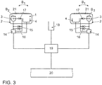
- the headlamp assembly generally in FIG. 3 is shown comprises two spaced headlights 1 and 2, which are arranged in front on the right and left side of the vehicle in a known per se.
- One of these headlights 1, 2 is in Fig. 1 shown.
- the arranged on the other side headlight 2 is mirror-inverted constructed substantially identical.
- FIG. 1 is a section through the left headlamp 1 shown in a plane which is parallel to the plane spanned by the vehicle transverse axis QA and the vertical V plane.
- the headlamp 1 comprises a first 3 and a second module 4. With the first module 3, a first partial light distribution and with the second module, a second partial light distribution can be generated, which generate an identical light function.
- the headlight 1 comprises additional modules 5 and 6, by means of which additional lighting functions can be realized.
- the module 5, for example, realize a cornering light and the module 6 provide an apron illumination of a low beam function.
- the first module 3 is designed as a projection module.
- the first module 3 comprises, in a manner known per se, a light source 7 which is surrounded by a reflector 8 designed as an ellipsoid of revolution.
- the reflector 8 thus has two focal points.
- the light source 7 is located in one of the focal points of the reflector 8.
- the light emitted by the light source 7 is reflected by the reflector 8 in the light emission direction L of the first module 3 in the direction of a projection lens 9.
- a diaphragm arrangement with the areal diaphragms 10 and 11 is arranged at the focal point of the projection lens 9 and close to the second focal point of the reflector 8.
- the normals of the areal apertures 10 and 11 are aligned substantially parallel to the light emission direction L.
- the light source 7, the reflector 8, the lens 9 and the apertures 10, 11 are arranged within a housing 12.
- the shape of the light-dark boundary of the first partial light distribution of the first module 3 can be changed by moving the diaphragms 10 and 11 in the vertical and / or horizontal direction in the beam path of the light emitted by the light source 7.
- the apertures 10 and 11 both a vertical and a horizontal cut-off line can be generated, whereby the vertical cut-off line can be shifted substantially steplessly to the left and right and the horizontal cut-off line in the Essentially infinitely shift up and down.
- a shift of the horizontal cut-off line also becomes by pivoting the first module 3 about a horizontal axis realized.
- An aperture 11, which is movable in the horizontal direction in the beam path, is then not necessary.
- a combination of movable panels 10, 11 and pivotable first module 3 about a horizontal and a vertical axis is possible.
- the second module 4 comprises a plurality of light sources 13, which are light-emitting diodes which are arranged in a housing.
- the light emitting diodes are divided into vertical rows 55 to 62 in the matrix.
- the rows 55 to 62 are individually and / or jointly controllable, so that different partial light distributions can be generated. This will be explained later.
- the light emitted from the light emitting diodes 13 is emitted in the light emission direction L.
- the number of light emitting diodes arranged per vertical row can be arbitrary. In particular, only one light-emitting diode can be arranged per vertical row.
- FIG. 3 an embodiment of the headlamp assembly will be described, which comprises on the right and left side in each case a headlight 1, 2, as in FIG. 1 is shown.
- the headlights 1, 2 are each connected to a control unit 14. By means of the control devices 14, the partial light distributions of the headlights 1 and 2 are controlled, which superimposed give an overall light distribution.
- the control devices 14 control a headlight range adjustment for the headlights 1 and 2, in which the headlights 1 and 2 are pivotable about a horizontal axis by means of the actuators 16. Furthermore, the control devices 14 control the actuators 15, with which the headlights 1 and 2 are pivotable about a vertical axis. By means of the actuators 15, the light emission direction L of the headlamp 1 and the headlamp 2 can be pivoted in the direction of the arrow B 1 .
- the actuators 15 are for example part of an already existing cornering light.
- the first modules 3 are pivotable about a horizontal axis solely by means of the actuators 16, so that they in the direction of the arrow A (see FIG. 2a ) are pivoted by means of the actuators 15 about a vertical axis, so that they are pivoted in the direction of the arrow B 2 .
- the first modules 3 are independently pivotable.
- control devices 14 control the vertical and / or horizontal position of the diaphragms 10 and 11 of the first module 3 for the right and left headlamps 1, 2 by means of the actuators 17.
- the actuators 17 comprise a stepping motor whose shaft is about an axis of rotation rotates. With this axis of rotation is coupled via a radial connecting element, a pin which moves during operation of the stepping motor on a circular path.
- the first partial light distribution can also be generated by a rotatable diaphragm shaft, which is provided with at least one focal line for producing the first partial light distribution.
- the axis of rotation can be brought via a gear in different rotational positions and translationally displaced in the beam path of the light emitted from the first light source 7. The rotation is then carried out via the actuators 14 and the translational displacement via the actuators 15.
- a blinding wave is for example in the EP 0 935 728 B1 described.
- FIG. 3 also shows that the headlights 1 and 2 are closed by light disks 21.
- the lenses 21 may be wholly or partially formed as a lens. Preferably, they are where they cover the first module 3 as a diffuser 21 and where they cover the second module 4, designed as a clear disc.
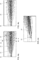
- FIGS. 4a to 4c The following are related to the FIGS. 4a to 4c described first and second partial light distributions of a high beam function, which can be generated by the headlamps 1 and 2 of the headlamp assembly generally.
- the diaphragms 10 and 11 are not in the beam path of the light emitted by the light source 7 and all light emitting diodes 13 of the second module are in the initial situation of FIG. 4a switched on:
- the total light distribution produced by the headlamp assembly is shown by a light-dark boundary on a road, being divided into two partial light distributions 23 and 24.
- the total light distribution of the high beam is regulated as a function of the speed of the vehicle.
- total light distribution can be set at a speed of, for example v ⁇ 90 km / h. Other speed limits from which the total light distribution is set are also possible.
- the total light distribution is composed of a first partial light distribution 23 generated by the first modules 3 and a second partial light distribution 24 generated by the second modules 4.
- the second partial light distribution 24 emerges beyond the light-dark boundary of the first partial light distribution 23.
- the area in front of the vehicle 22 is divided into a vehicle-related area 30 and a vehicle-distant area 31.
- the light-dark boundary of the total light distribution is generated by the first partial light distribution 23.
- the light-dark boundary is generated by the second partial light distribution 24.
- the first partial light distribution 23 in the vicinity of the vehicle 22 is wider than the second partial light distribution 24, the first partial light distribution 23 ensures a wide illumination of the traveled lane in the vehicle-proximate area 30.
- the second partial light distribution 24 generates a light-dark boundary in the vehicle-distant region 31 which is wider than the light-dark boundary of the first partial light distribution 23.
- the width of the light-dark boundary of the second partial light distribution 24 is of the width the area occupied by light emitting diodes 13 dependent.
- the second partial light distribution 24 has a broader cut-off line in the vehicle-distant area 31, it can be ensured that the driver of the vehicle 22 can already recognize dangers on or next to the road from a long distance. As a result, any necessary reactions can be initiated earlier.
- the second partial light distribution 24 generated by the second module 4 of the left headlamp 1 is further subdivided into a plurality of partial areas 25 to 29.
- the brightness of the subregions 25 to 29 decreases from the inside to the outside.
- the outermost subregion 25 accordingly has the lowest brightness of the subregions 25 to 29.
- the second partial light distribution 24 generated by the second module 4 of the right headlamp 2 is likewise subdivided into a plurality of partial areas 25 to 28.
- the innermost rows 55 and 56 of LEDs 13 are not turned on.
- the first partial light distribution 23 has a region 33 which is not illuminated by the second partial light distribution 24.
- This area 33 is located directly in front of the vehicle 22. This ensures that this area 33 is also sufficiently illuminated.
- the superposition of the first 23 and the second partial light distribution 24 generates a high beam, which provides a brighter light in the area in which the luminous intensities of both light distributions 23 and 24 add up, while areas using only one of the two light distributions 23 or 24 are not lit, also illuminated.
- the combination of the first 3 and the second module 4 thus leads overall to a brighter overall light distribution with wider illumination.
- total light distribution represents a high beam function at a speed of, for example v ⁇ 90 km / h.
- the first 23 and the second partial light distribution 24 are constructed in principle, as in FIG. 4a is shown.
- the headlight range is mainly regulated by the second partial light distribution 24.
- the first partial light distribution 23 changes compared to the first partial light distribution 23, as in FIG. 4a not shown.
- Figure 4c is the total light distribution when driving around a left turn shown.
- the curve is detected and the first partial light distribution 23 is also led to the left by pivoting the first modules to the left.
- the second partial light distribution 24 is thereby "pivoted" to the left, that increased light emitting diodes of the second module 4 of the left headlamp 2 are turned on.
- the outer rows 61 and 62 of LEDs of the left second module 4 are turned on, which now produce the outermost portions 25 and 26 of the second module 4 of the left headlight 1 generated part of the second partial light distribution 24.
- the innermost rows 55 and 56 of the left second module 4 are turned off.
- the part of the second partial light distribution 24 generated by the second module 4 of the right-hand headlight 2 is reduced overall in its brightness and width by driving corresponding rows of light-emitting diodes 13.
- the driver has the impression that the second partial light distribution 24 would be pivoted to the left as well as the first partial light distribution.
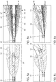
- FIGS. 5a, 5c and 5e For reasons of clarity, the masked long duration light produced by the first modules 3 is shown.
- FIGS. 5b, 5d and 5f show the superposition of the first partial light distribution 36 and the second partial light distribution 37 to a total light distribution, which can be produced by the method according to the invention:
- the starting point is a total light distribution as in FIG. 4a is shown.
- a preceding road user 34 is detected by the camera 18.
- the way in which the oncoming traffic participant is detected for example, in the DE 10 2009 054 227 A1 whose contents are incorporated by reference into the present application.
- the diaphragms 10 and 11 are then pushed into the beam path of the light emitted by the light source 7 of the first module 3 in such a way that on the roadway in the FIG. 5a shown first partial light distribution 36 is formed.
- first partial light distribution 36 has in the area M a headlight range, which is controlled so that it is at least less than the distance to the detected road user 34.
- a side area S 1 is formed, in which the headlight range is greater than the headlight range in the area M of the first partial light distribution 36. Beside the road user 34 is thus waivegesuitedt to the driver of Vehicle 22 to provide better illumination of the traffic area in front of the vehicle 22.
- the headlight range in the side area S 1 for example, the headlight range in a conventional high beam function correspond.
- a side area S 2 is formed, which also has a wider headlight range than the headlight range in the central region M.
- the headlight range of the side area S 2 corresponds to the headlight range of a conventional high beam function, so that the total light distribution corresponds to a conventional high beam in which, in the light distribution, an area at the detected road user 34 and in the direction of travel in front of the road user 22 is cut out.
- FIG. 5b a superposition of the second partial light distribution 37 generated by the second modules 4 with the first partial light distribution 36 is shown.
- the second partial light distribution 37 has two partial light beams 46 and 47, wherein a light beam 46 from the second module 4 of the left headlamp 1 and a light beam 47 from the second module 4 of the right headlamp 2 is generated.
- the left light beam 46 radiates on the left and the right light beam 47 passes right on the detected road user 34.
- the brightnesses of the first partial light distribution 36 and the second partial light distribution 37 add up in the two side regions S 1 and S 2 , while in the middle region M, only the first partial light distribution 36 provides illumination.
- the left light beam 46 of the second partial light distribution 37 is divided into subregions 42 to 45.
- the subregion 42 of the rows 58 and 59 and the subregions 43 to 45 corresponding to the rows 60 to 62 of light emitting diodes 13 of the left second module 4 are generated.
- the right light beam 47 is divided into the subregions 42, 44 and 45.
- the same reference numerals for the subregions of the left-hand 46 and right-hand light beams 47 mean the same brightnesses.
- the subregion 42 is generated by the rows 59 and 60 and the subregions 44 and 45 correspondingly by the rows 61 and 62 of light emitting diodes 13 of the right second module 4.
- the inner rows 55 to 57 of light emitting diodes 13 of the left second 4 and the inner rows 55 to 58 of light emitting diodes 13 of the right second module 4 are turned off.
- the central region M produces an edge 39 whose distance from the headlamp assembly depends on the beam width and the position of the diaphragms 10 and 11 in the beam path of the light emitted by the light source 7 of the first module 3. Furthermore, the side regions S 1 and S 2 , which are generated by the second partial light distribution 37, in the longitudinal direction LR to the vehicle 22 also produce two edges 40 and 41 whose distance to each other in the transverse direction QR to the vehicle 22 depends on the width of the detected vehicle 34. By the edges 39, 40 and 41, a light-free corridor 38 is formed, in which the detected vehicle 34 is located.
- FIG. 5b Compared to the sole first partial light distribution 36 off FIG. 5a , which generally corresponds to the total light distribution of the prior art masked longsight described in the prior art, it will be seen that the total light distribution consisting of the first 36 and second partial light distributions 37 FIG. 5b is not only brighter by adding the brightnesses of both partial light distributions 36 and 37, but also by the second partial light distribution 37 has a broader lighting range and the light-free corridor 38 can be very closely brought to the detected road users 34.
- the total light distribution consisting of the two partial light distributions 36 and 37 thus has overall a larger and further light field and in some areas a higher brightness without dazzling the vehicle driver 34 ahead.
- a soft transition between the light box and non-illuminated field can also be created.
- FIG. 5c the first partial light distribution 36 is shown when driving through a left turn. It is clear that the light range of the side area S 2 is lowered so far that it substantially coincides with the light range of the central region M. This is due to the fact that the diaphragms 10 and 11 must be displaced in the beam path of the light emitted by the light source 7 of the left first module 3 such that the light-free corridor 38 can track the detected road user 34. The displacement leads from a certain position of the aperture 10 and 11 to light that would produce the side area S 2 in the first light distribution 36 is shaded. The side region S 2 can no longer be formed by the first partial light distribution, as a result of which this side region S 2 remains completely unlit.
- the second partial light distribution 37 is generally structured as in FIG FIG. 5b ,
- the rows 55 and 56 of light-emitting diodes 13 which are illuminated in FIG FIG. 5b the inner portions 42 and 43 of the light beam 46 have generated turned off, so that the left light beam 46 now has a smaller width and only of the rows 57, 58 and 59, wherein the rows 58 and 59 emit light of the same luminance generated becomes.
- the right light beam 47 remains unchanged.
- the distance 35 between side area S 1 and detected road user 34 can be drastically reduced in this way, so that the light-free corridor 38 reaches up to the detected road user 34.
- the first partial light distribution 36 is shown when driving through a tight bend. It no longer differs from the first partial light distribution 36 in a normal curve, as in FIG. 5c shown.
- the distance 35 between the detected road user 34 and the side area S 1 is even greater than in FIG. 5b ,
- FIG. 5f In turn, an overall light distribution is shown, which is produced by the superimposition of the first 36 and the second partial light distribution 37.
- the LEDs 13 of the second module 4 of the left headlamp 2 are driven so that the left light beam 46 is divided into two partial light beams 48 and 49. This is done by turning off the rows 58 and 59 of light emitting diodes 13 which originally produced the subregions 42 and 43 of the left light beam 46. For this purpose, the subregions 42 and 43 are generated by the rows 56 and 57 of light emitting diodes 13. In addition, the innermost row 55 of LEDs 13 is turned on, so that an additional portion 50 is generated. This exudes the Partial light beam 49 right past the leading road user 34, and no longer as originally left on the leading road user 34 over. As a result, the right-hand light beam 47 and the partial-light beam 49 of the left-hand light beam 46 are superimposed, thus ensuring brighter illumination in the region to the right of the vehicle driver 34 ahead.
- the distance 35 between side area S 1 and detected road user 34 can be drastically reduced in this way.
- Subregions 45 and 44 are generated unchanged by the same rows 61 and 62 of light emitting diodes 13, as in FIG. 5d shown. As a result, the second partial light beam 48 is guided past the preceding vehicle on the left.
- FIGS. 5c, 5d . 5e and 5f is exemplified a ride through a left turn.
- the first 36 and the second partial light distribution 37 are generated in the same way only by mirrored driving of the first 3 and second module 4.
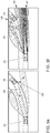
- FIGS. 6a to 6f are in the same way as in the FIGS. 5a to 5f first explained the first partial light distribution 36 alone in a traffic situation with an oncoming vehicle.
- a perspective view for clarifying the conclusion of the partial light distributions 36 and 37 by different positions of the first 3 and second modules 4 is shown.
- the partial light distributions 36 and 37 are shown schematically as they can be seen on a screen which is placed in front of the vehicle 22 at a certain distance.
- FIGS. 4a to 4c and 5b are shown schematically as they can be seen on a screen which is placed in front of the vehicle 22 at a certain distance.
- the headlight ranges of the second partial light distribution 37 are generally wider than the headlight ranges of the first partial light distribution 36 Figures 6b, 6d and 6f the second partial light distribution 37 is represented by a lower line density in the hatching.
- the partial light distributions 36 and 37 are regulated in the case of an oncoming traffic participant 53, as in the case of the preceding road user 34, when cornering.
- the starting point of the method according to the invention is again an overall light distribution of the high-beam function as shown in FIG. 4a is shown.
- an oncoming traffic participant 53 is detected by the camera 18.
- the diaphragms 10 and 11 are introduced into the beam path of the light emitted by the light source 7 of the first module 3 in such a way that in the light distribution a recess 54, as shown in FIG FIG. 6a shown forms.
- the recess 54 is placed where the oncoming road user 53 is located. On the road, this leads to the formation of the central region M and the two side regions S 1 and S 2 .
- the light emitting diodes 13 of the second module 4 are controlled by the control device 14 in such a way that the rows 55 and 56 of light emitting diodes 13, which are arranged at the innermost position in the second modules 4, are switched off.
- the number of rows that are turned off depends on the width and distance of the oncoming traffic participant 53.
- a recess in the second partial light distribution is generated at the same point as in the first partial light distribution.
- the superimposed partial light distribution 36 and 37 are in FIG. 6b shown. It becomes particularly clear that the second partial light distribution 37 also provides illumination in the outer and inner regions in which the first partial light distribution 36 does not provide illumination, while the first partial light distribution 36 illuminates there where the second partial light distribution 37 does not illuminate.
- the second partial light distribution 37 provides, in particular, no illumination in advance 63 of the vehicle 22.
- the light-free corridor 38 is generated on the road, in which the oncoming vehicle 53 moves.
- the distance of the vehicle 22 to the oncoming traffic participant 53 decreases. From a certain distance, the direction of travel 51 of the vehicle 22 and the connection line 52 are from the vehicle 22 to the oncoming vehicle 53 an angle ⁇ , which increases with decreasing distance.
- FIG. 6c an adaptation of the recess 54 to the oncoming traffic participant in the first partial light distribution 36 is shown.
- the apertures 10 and 11 of the first modules 3 are shifted vertically to the left and horizontally downwards. This results in an offset to the left and the distance of the oncoming vehicle 53 offset recess in the first partial light distribution 36.
- only the aperture 10 can be moved vertically to the left, while simultaneously adapted to adjust the beam width, the first module 3 about a horizontal axis becomes.
- FIG. 6d shows the superimposed first 36 and second partial light distributions 37.
- the second modules 4 are driven such that the light emitting diodes 13, which were previously turned off to produce the recess in the second partial light distribution 37, at least partially turned on, while other light emitting diodes 13, the were previously turned on to generate the side area S 2 , at least partially turned off.
- the LEDs 13 are turned on or off, that forms a new, offset to the left recess 54 in the second partial light distribution 37.
- the luminous range of the first partial light distribution in the side region S 2 must be lowered at a certain angle ⁇ such that it coincides with the luminous range of the first partial light distribution in the middle region M. This is FIG. 6e shown. This happens when a maximum displacement position of the aperture 10 and 11 of the left first module 3 is reached.
- FIG. 6c It will be seen that at a certain angle ⁇ in the side region S 2, the first partial light distribution 36 no longer contributes to the total light distribution.
- the light-emitting diodes 13 which provide the sole illumination of the side region S 2 must then be switched off.
- first and second partial light distributions are then combinations of the first and second partial light distributions of FIGS. 5b . d and f and 6b, d and f.
- FIG DE 10 2009 054 227 A1 A detailed headlight range control as a function of the horizontal angle ⁇ for the first partial light distribution 36 is shown in FIG DE 10 2009 054 227 A1 whose contents are incorporated by reference into the present application.
- a low-beam function can also be provided.
Landscapes
- Engineering & Computer Science (AREA)
- General Engineering & Computer Science (AREA)
- Physics & Mathematics (AREA)
- Microelectronics & Electronic Packaging (AREA)
- Optics & Photonics (AREA)
- Mechanical Engineering (AREA)
- Mathematical Physics (AREA)
- Lighting Device Outwards From Vehicle And Optical Signal (AREA)
- Non-Portable Lighting Devices Or Systems Thereof (AREA)
Claims (9)
- Procédé de commande d'un ensemble de phares d'un véhicule (22) présentant au moins deux phares (1, 2) disposés à distance mutuelle,
le procédé permettant de former une répartition globale de la lumière,
chacun des deux phares (1, 2) comportant au moins un premier module (3) et un deuxième module (4) séparés l'un de l'autre,
chacun des premiers modules (3) comportant au moins une source de lumière (7) et au moins un élément mobile (10, 11) qui peut être amené dans le parcours des rayons de la lumière émise par la source de lumière (7) et
chacun des deuxièmes modules (4) comportant plusieurs sources de lumière (13) disposées en matrice,
une première répartition partielle (23, 36) d'une fonction lumineuse des premiers modules (3) étant formée par modification de la position du ou des éléments mobiles (10, 11),
une deuxième répartition partielle (24, 37) de la même fonction lumineuse étant formée par les deuxièmes modules (4) par commande de différentes sources de lumière (13) ou de plusieurs groupes de sources de lumière (13) parmi les différentes sources de lumière (13) et
la répartition globale de la fonction lumineuse étant formée en superposant la première répartition partielle (23, 36) et la deuxième répartition partielle (24, 37),
caractérisé en ce que
au moins un véhicule (34, 53) en circulation dans la direction de la lumière émise par l'ensemble de phare est détecté,
la première répartition partielle (36) présente une partie centrale (M) dont la portée d'éclairage est plus petite que la distance s'étendant jusqu'au véhicule (34, 53) en circulation qui a été détecté et deux parties latérales (S1, S2) formées des deux côtés de la partie centrale (M) et dont les portées d'éclairage sont supérieures à la portée d'éclairage de la partie centrale (M) et
la deuxième répartition partielle (37) présente uniquement dans les parties latérales (S1, S2) de la première répartition partielle (36) des portées d'éclairage supérieures à la distance s'étendant jusqu'au véhicule (34, 53) en circulation qui a été détecté. - Procédé selon la revendication 1, caractérisé en ce que sur une frontière (32), la deuxième répartition partielle (24, 37) déborde de la limite clarté-obscurité de la première répartition partielle (23, 36) et la zone située en avant du véhicule (22) est ainsi divisée en une partie (30) proche du véhicule et une partie (31) éloignée du véhicule, la limite clarté-obscurité de la répartition globale de la lumière étant formée par la première répartition partielle (23, 36) dans la partie (30) proche du véhicule et par la deuxième répartition partielle (24, 37) dans la partie (31) éloignée du véhicule.
- Procédé selon les revendications 1 ou 2,
caractérisé en ce qu'un corridor (38) exempt de lumière est formé dans la répartition globale de la lumière par la partie centrale (M) et les parties latérales (S1, S2) et présente un bord (39) formée par la partie centrale (M) dans la direction (QR) transversale par rapport au véhicule (22) et deux bords (40, 41) formés par les parties latérales (S1, S2) dans la direction longitudinale (LR) du véhicule (22), les bords (40, 41) formés par les parties latérales (S1, S2) étant formés essentiellement par la deuxième répartition partielle (37) et la distance dans la direction transversale (QR) entre les bords (40, 41) formés par les parties latérales (S1, S2) dépendant de la largeur du véhicule (34, 53) en circulation qui a été détecté. - Procédé selon l'une des revendications 1 à 3,
caractérisé en ce que la portée d'éclairage de la première répartition partielle (36) dans au moins une partie latérale (S1, S2) est abaissée en fonction de l'angle horizontal (φ) entre la direction de roulage (51) du véhicule (22) et la ligne (52) qui relie le véhicule (22) au véhicule (34, 53) en circulation qui a été détecté, de telle sorte qu'à partir d'un certain angle (φ) la partie latérale (S1, S2) n'est formée que par la deuxième répartition partielle (37). - Procédé selon la revendication 4, caractérisé en ce que la deuxième répartition partielle (37) est formée par au moins deux rayons lumineux (46, 47), au moins l'un (46) de ces deux rayons lumineux étant divisé en deux rayons lumineux partiels (48, 49) en fonction de l'angle horizontal (φ) entre la direction de roulage (51) du véhicule (22) et la ligne (52) qui relie le véhicule (22) au véhicule (34, 53) en circulation qui a été détecté, de telle sorte qu'un rayon lumineux partiel (48) forme seul une partie latérale (S2) et l'autre rayon lumineux partiel (49) forme l'autre partie latérale (S1) en même temps qu'au moins l'autre rayon lumineux (47) de la deuxième répartition partielle (37).
- Procédé selon l'une des revendications 1 à 5,
caractérisé en ce que la deuxième répartition partielle (37) est divisée dans les parties latérales (S1, S2) en plusieurs parties (42, 43, 44, 45, 50), l'intensité d'éclairage diminuant de la partie (42, 50) située le plus à l'intérieur à la partie (45) située le plus à l'extérieur. - Procédé selon l'une des revendications 1 à 6,
caractérisé en ce que la fonction lumineuse est une fonction d'éclairage lointain. - Ensemble de phares pour un véhicule (22), présentant au moins deux phares (1, 2) disposés à distance mutuelle et permettant de former une répartition globale de la lumière,
chacun des deux phares (1, 2) comportant au moins un premier module (3) et un deuxième module (4) séparés l'un de l'autre,
chacun des premiers modules (3) comportant au moins une source de lumière (7) et au moins un élément mobile (10, 11) qui peut être amené dans le parcours des rayons de la lumière émise par la source de lumière (7) et chacun des deuxièmes modules (4) comportant plusieurs sources de lumière (13) disposées en matrice,
un ensemble de commande (14) par lequel les premiers modules (3) peuvent être commandés de telle sorte qu'une première répartition partielle (23, 36) d'une fonction lumineuse peut être formée par modification de la position du ou des éléments mobiles (10, 11), par lequel les deuxièmes modules (4) peuvent être commandés de telle sorte qu'une deuxième répartition partielle (24, 37) de la même fonction lumineuse est formée par commande de différentes sources de lumière (13) ou de plusieurs groupes de sources de lumière (13) parmi les différentes sources de lumière (13) et par lequel les phares (1, 2) peuvent être commandés de telle sorte que la répartition globale de la lumière peut être formée par superposition des premières (23, 36) et des deuxièmes (24, 37) répartitions de lumière, et
un dispositif raccordé à l'ensemble de commande et détectant les véhicules circulant en avant du véhicule dans la direction de son déplacement,
caractérisé en ce que
lors de la détection d'un véhicule (34, 53) en circulation dans la direction de l'émission de lumière de l'ensemble de phares,
la première répartition partielle (36) présente une partie centrale (M) dont la portée d'éclairage est plus petite que la distance s'étendant jusqu'au véhicule (34, 53) en circulation qui a été détecté et deux parties latérales (S1, S2) formées des deux côtés de la partie centrale (M) et dont les portées d'éclairage sont supérieures à la portée d'éclairage de la partie centrale (M) et
la deuxième répartition partielle (37) présente uniquement dans les parties latérales (S1, S2) de la première répartition partielle (36) des portées d'éclairage supérieures à la distance s'étendant jusqu'au véhicule (34, 53) en circulation qui a été détecté. - Ensemble de phare selon la revendication 8,
caractérisé en ce que la ou les sources de lumière (7) du premier module (3) et/ou les différentes sources de lumière (13) du deuxième module (4) sont des diodes luminescentes et en ce que l'élément mobile du premier module comporte au moins un écran (10, 11) dont la position peut être modifiée.
Applications Claiming Priority (2)
| Application Number | Priority Date | Filing Date | Title |
|---|---|---|---|
| DE102013216318.5A DE102013216318A1 (de) | 2013-08-16 | 2013-08-16 | Verfahren zum Steuern einer Scheinwerferanordnung für ein Fahrzeug und Scheinwerferanordnung |
| PCT/EP2014/063820 WO2015022115A1 (fr) | 2013-08-16 | 2014-06-30 | Procédé permettant de commander un ensemble de projecteurs pour véhicule et ensemble de projecteurs |
Publications (2)
| Publication Number | Publication Date |
|---|---|
| EP3033248A1 EP3033248A1 (fr) | 2016-06-22 |
| EP3033248B1 true EP3033248B1 (fr) | 2018-10-10 |
Family
ID=51162743
Family Applications (1)
| Application Number | Title | Priority Date | Filing Date |
|---|---|---|---|
| EP14736702.3A Active EP3033248B1 (fr) | 2013-08-16 | 2014-06-30 | Procédé permettant de commander un ensemble de projecteurs pour véhicule et ensemble de projecteurs |
Country Status (5)
| Country | Link |
|---|---|
| EP (1) | EP3033248B1 (fr) |
| KR (1) | KR101749467B1 (fr) |
| CN (1) | CN105452058B (fr) |
| DE (1) | DE102013216318A1 (fr) |
| WO (1) | WO2015022115A1 (fr) |
Cited By (1)
| Publication number | Priority date | Publication date | Assignee | Title |
|---|---|---|---|---|
| WO2024233591A1 (fr) * | 2023-05-11 | 2024-11-14 | Valeo Vision | Phare pour véhicule |
Families Citing this family (16)
| Publication number | Priority date | Publication date | Assignee | Title |
|---|---|---|---|---|
| DE102014009592A1 (de) * | 2014-06-27 | 2015-12-31 | Audi Ag | Scheinwerfervorrichtung für ein Kraftfahrzeug, Kraftfahrzeug und Verfahren zum Betreiben einer Scheinwerfervorrichtung |
| CN106166980A (zh) | 2015-05-22 | 2016-11-30 | 福特全球技术公司 | 用于控制前照灯的方法和装置 |
| FR3038697B1 (fr) * | 2015-07-10 | 2017-08-11 | Valeo Vision | Procede de controle d’un faisceau lumineux et module d’eclairage et/ou de signalisation correspondant |
| DE102015012416A1 (de) * | 2015-09-25 | 2017-03-30 | Audi Ag | Projizieren eines vorgebbaren Lichtmusters |
| KR101968661B1 (ko) * | 2015-12-29 | 2019-04-12 | 에스엘 주식회사 | 차량용 램프 및 상기 차량용 램프를 제어하는 방법 |
| JP6751307B2 (ja) * | 2016-05-17 | 2020-09-02 | スタンレー電気株式会社 | 車両用灯具 |
| DE102016211552A1 (de) * | 2016-06-28 | 2017-12-28 | Bayerische Motoren Werke Aktiengesellschaft | Kraftfahrzeug |
| DE102016122492A1 (de) * | 2016-11-22 | 2018-05-24 | HELLA GmbH & Co. KGaA | Erzeugung einer homogenen Lichtverteilung in Abhängigkeit von der Topografie und der gemessenen Leuchtdichte |
| DE102017214346A1 (de) | 2017-08-17 | 2019-02-21 | Volkswagen Aktiengesellschaft | Scheinwerfer für ein Fahrzeug |
| JP6992428B2 (ja) * | 2017-11-15 | 2022-02-04 | 市光工業株式会社 | 車両用灯具 |
| EP3671017A1 (fr) * | 2018-12-18 | 2020-06-24 | ZKW Group GmbH | Système d'éclairage pour un véhicule automobile |
| CN113412391B (zh) * | 2019-02-21 | 2023-12-08 | 海拉有限双合股份公司 | 照明装置、特别地用于车辆的照明装置 |
| DE102019005674B4 (de) * | 2019-08-13 | 2026-03-12 | Mercedes-Benz Group AG | Verfahren zum Steuern einer variablen Lichtverteilung |
| DE102020115384B4 (de) * | 2020-06-10 | 2023-03-16 | HELLA GmbH & Co. KGaA | Verfahren zur Steuerung zweier Beleuchtungsmodule eines Scheinwerfers, System mit einem Scheinwerfer mit zwei Beleuchtungsmodulen und einer Steuerungseinheit zur Ausführung des Verfahrens und Kraftfahrzeug mit einem solchen System |
| CN115899610A (zh) * | 2021-08-16 | 2023-04-04 | 华为技术有限公司 | 一种车灯模块、灯光系统以及车辆 |
| CN115143424B (zh) * | 2022-08-02 | 2024-09-17 | 张帅 | 一种发动机的前大灯照明系统 |
Citations (1)
| Publication number | Priority date | Publication date | Assignee | Title |
|---|---|---|---|---|
| DE202010001654U1 (de) * | 2010-02-01 | 2010-05-20 | Delvis Gmbh | Leuchtsystem für ein Kraftfahrzeug |
Family Cites Families (17)
| Publication number | Priority date | Publication date | Assignee | Title |
|---|---|---|---|---|
| DE19739089A1 (de) | 1997-09-06 | 1999-03-11 | Hella Kg Hueck & Co | Scheinwerfer für Fahrzeuge |
| DE10009782B4 (de) | 2000-03-01 | 2010-08-12 | Automotive Lighting Reutlingen Gmbh | Beleuchtungseinrichtung eines Fahrzeugs |
| DE102006038915A1 (de) * | 2006-08-18 | 2008-02-21 | Hella Kgaa Hueck & Co. | Beleuchtungssystem für Fahrzeuge |
| DE102007045150B4 (de) | 2006-09-27 | 2021-03-04 | HELLA GmbH & Co. KGaA | Scheinwerferanordnung für ein Fahrzeug und Verfahren zum Steuern einer Scheinwerferanordnung |
| DE102007054048A1 (de) * | 2007-11-13 | 2009-05-14 | Daimler Ag | Verfahren und Vorrichtung für eine Fahrlichtsteuerung eines Fahrzeugs |
| DE102008036193B4 (de) * | 2008-08-02 | 2020-03-12 | Automotive Lighting Reutlingen Gmbh | Beleuchtungseinrichtung für ein Kraftfahrzeug |
| DE102008060949B4 (de) * | 2008-12-06 | 2023-09-28 | Mercedes-Benz Group AG | Verfahren und Anordnung zur Ansteuerung von Fahrzeugscheinwerfern |
| JP2010192411A (ja) * | 2009-02-20 | 2010-09-02 | Koito Mfg Co Ltd | 車輌用前照灯 |
| DE102009054227B4 (de) | 2009-11-21 | 2025-10-02 | Volkswagen Ag | Verfahren zum Steuern einer Scheinwerferanordnung für ein Fahrzeug und Scheinwerferanordnung |
| DE102009054228B4 (de) | 2009-11-21 | 2025-07-17 | Volkswagen Ag | Verfahren zum Steuern einer Schweinwerferanordnung für ein Fahrzeug und Scheinwerferanordnung |
| DE102009054248B4 (de) | 2009-11-21 | 2025-04-24 | Volkswagen Ag | Verfahren zum Steuern einer Scheinwerferanordnung für ein Fahrzeug und Scheinwerferanordnung |
| DE102009054249B4 (de) | 2009-11-21 | 2025-07-24 | Volkswagen Ag | Verfahren zum Steuern einer Scheinwerferanordnung für ein Fahrzeug und Scheinwerferanordnung |
| DE102009054238A1 (de) | 2009-11-21 | 2011-05-26 | Volkswagen Ag | Verfahren zum Steuern einer Scheinwerferanordnung für ein Fahrzeug und Scheinwerferanordnung |
| DE102009060781A1 (de) | 2009-12-22 | 2011-06-30 | Automotive Lighting Reutlingen GmbH, 72762 | Lichtmodul für eine Beleuchtungseinrichtung eines Kraftfahrzeugs sowie Beleuchtungseinrichtung mit einem solchen Lichtmodul |
| JP5716320B2 (ja) * | 2010-08-26 | 2015-05-13 | 市光工業株式会社 | 車両用前照灯および車両用前照灯装置 |
| DE102011112716A1 (de) | 2011-09-07 | 2013-03-07 | Audi Ag | Verfahren zum Betreiben eines Scheinwerfers eines Kraftfahrzeugs |
| DE102012103313A1 (de) * | 2012-04-17 | 2013-10-17 | Hella Kgaa Hueck & Co. | Lichtmodul für den Scheinwerfer eines Fahrzeugs |
-
2013
- 2013-08-16 DE DE102013216318.5A patent/DE102013216318A1/de not_active Withdrawn
-
2014
- 2014-06-30 KR KR1020167003066A patent/KR101749467B1/ko not_active Expired - Fee Related
- 2014-06-30 EP EP14736702.3A patent/EP3033248B1/fr active Active
- 2014-06-30 WO PCT/EP2014/063820 patent/WO2015022115A1/fr not_active Ceased
- 2014-06-30 CN CN201480042698.1A patent/CN105452058B/zh not_active Expired - Fee Related
Patent Citations (1)
| Publication number | Priority date | Publication date | Assignee | Title |
|---|---|---|---|---|
| DE202010001654U1 (de) * | 2010-02-01 | 2010-05-20 | Delvis Gmbh | Leuchtsystem für ein Kraftfahrzeug |
Cited By (2)
| Publication number | Priority date | Publication date | Assignee | Title |
|---|---|---|---|---|
| WO2024233591A1 (fr) * | 2023-05-11 | 2024-11-14 | Valeo Vision | Phare pour véhicule |
| US12163637B2 (en) | 2023-05-11 | 2024-12-10 | Valeo Vision | Headlamp for a vehicle |
Also Published As
| Publication number | Publication date |
|---|---|
| KR101749467B1 (ko) | 2017-06-20 |
| WO2015022115A1 (fr) | 2015-02-19 |
| KR20160027190A (ko) | 2016-03-09 |
| CN105452058B (zh) | 2017-11-17 |
| DE102013216318A1 (de) | 2015-02-19 |
| CN105452058A (zh) | 2016-03-30 |
| EP3033248A1 (fr) | 2016-06-22 |
Similar Documents
| Publication | Publication Date | Title |
|---|---|---|
| EP3033248B1 (fr) | Procédé permettant de commander un ensemble de projecteurs pour véhicule et ensemble de projecteurs | |
| EP3343091B1 (fr) | Module d'éclairage de phare de véhicule automobile | |
| DE4313914C2 (de) | Kraftfahrzeugscheinwerfereinrichtung mit variierbarer Beleuchtungsstärkeverteilung | |
| DE19860461B4 (de) | Scheinwerferanlage für Fahrzeuge zur Erzeugung von Lichtbündeln mit unterschiedlicher Charakteristik | |
| DE102008036193B4 (de) | Beleuchtungseinrichtung für ein Kraftfahrzeug | |
| EP2518397B1 (fr) | Phare de véhicule avec un module de base et un module spot pour produire un faisceau de route et système de phare correspondant | |
| EP3430306B1 (fr) | Projecteur pour un véhicule automobile | |
| EP3402694B1 (fr) | Système de phare et procédé de fourniture d'une fonction d'éclairage de virage | |
| DE102007040042A1 (de) | System zum Erzeugen eines Lichtbündels im Vorfeld eines Kraftfahrzeuges | |
| EP2517929A2 (fr) | Module d'éclairage d'un véhicule automobile pour générer une répartition de base de la lumière des feux de route | |
| EP1826476B1 (fr) | Dispositif d'éclairage pour un véhicule | |
| WO2012045775A1 (fr) | Dispositif d'éclairage pour produire une fonction de phare à longue portée anti-éblouissant | |
| DE102012205437A1 (de) | Beleuchtungsvorrichtung für ein Kraftfahrzeug | |
| DE19807153A1 (de) | Scheinwerfer für Fahrzeuge nach dem Projektionsprinzip | |
| DE19961942A1 (de) | Scheinwerferanlage für Fahrzeuge zur Erzeugung von Lichtbündeln mit unterschiedlicher Charakteristik | |
| EP2982902A1 (fr) | Module lumineux de projection pour un phare de vehicule automobile | |
| DE102011001865A1 (de) | Beleuchtungsvorrichtung | |
| WO2018153906A1 (fr) | Modification d'un gradient de luminosité d'un phare par variation de points lumineux | |
| DE102017223441B4 (de) | Lichtsteuerungsvorrichtung zur Einteilung einer Lichtverteilung | |
| DE102007050374A1 (de) | Fahrzeugscheinwerfer und Verfahren zum Betrieb eines Fahrzeugscheinwerfers | |
| DE19914417B4 (de) | Scheinwerferanlage für Fahrzeuge mit wenigstens zwei Scheinwerfern für Abblendlicht | |
| EP3013673A1 (fr) | Phare de motocycle | |
| DE102011002282A1 (de) | Projektionsmodul mit variabler Lichtverteilung | |
| DE10044391A1 (de) | Scheinwerfer für Kraftfahrzeuge | |
| WO2019034306A1 (fr) | Phare conçu pour un véhicule |
Legal Events
| Date | Code | Title | Description |
|---|---|---|---|
| PUAI | Public reference made under article 153(3) epc to a published international application that has entered the european phase |
Free format text: ORIGINAL CODE: 0009012 |
|
| 17P | Request for examination filed |
Effective date: 20160316 |
|
| AK | Designated contracting states |
Kind code of ref document: A1 Designated state(s): AL AT BE BG CH CY CZ DE DK EE ES FI FR GB GR HR HU IE IS IT LI LT LU LV MC MK MT NL NO PL PT RO RS SE SI SK SM TR |
|
| AX | Request for extension of the european patent |
Extension state: BA ME |
|
| DAX | Request for extension of the european patent (deleted) | ||
| RIC1 | Information provided on ipc code assigned before grant |
Ipc: F21S 41/657 20180101ALI20180322BHEP Ipc: F21S 41/686 20180101ALI20180322BHEP Ipc: B60Q 1/14 20060101AFI20180322BHEP Ipc: F21S 41/663 20180101ALI20180322BHEP Ipc: F21S 41/143 20180101ALI20180322BHEP |
|
| GRAP | Despatch of communication of intention to grant a patent |
Free format text: ORIGINAL CODE: EPIDOSNIGR1 |
|
| STAA | Information on the status of an ep patent application or granted ep patent |
Free format text: STATUS: GRANT OF PATENT IS INTENDED |
|
| INTG | Intention to grant announced |
Effective date: 20180508 |
|
| GRAS | Grant fee paid |
Free format text: ORIGINAL CODE: EPIDOSNIGR3 |
|
| GRAA | (expected) grant |
Free format text: ORIGINAL CODE: 0009210 |
|
| STAA | Information on the status of an ep patent application or granted ep patent |
Free format text: STATUS: THE PATENT HAS BEEN GRANTED |
|
| AK | Designated contracting states |
Kind code of ref document: B1 Designated state(s): AL AT BE BG CH CY CZ DE DK EE ES FI FR GB GR HR HU IE IS IT LI LT LU LV MC MK MT NL NO PL PT RO RS SE SI SK SM TR |
|
| REG | Reference to a national code |
Ref country code: GB Ref legal event code: FG4D Free format text: NOT ENGLISH |
|
| REG | Reference to a national code |
Ref country code: CH Ref legal event code: EP Ref country code: AT Ref legal event code: REF Ref document number: 1050839 Country of ref document: AT Kind code of ref document: T Effective date: 20181015 |
|
| REG | Reference to a national code |
Ref country code: IE Ref legal event code: FG4D Free format text: LANGUAGE OF EP DOCUMENT: GERMAN |
|
| REG | Reference to a national code |
Ref country code: DE Ref legal event code: R096 Ref document number: 502014009720 Country of ref document: DE |
|
| REG | Reference to a national code |
Ref country code: NL Ref legal event code: MP Effective date: 20181010 |
|
| REG | Reference to a national code |
Ref country code: LT Ref legal event code: MG4D |
|
| PG25 | Lapsed in a contracting state [announced via postgrant information from national office to epo] |
Ref country code: NL Free format text: LAPSE BECAUSE OF FAILURE TO SUBMIT A TRANSLATION OF THE DESCRIPTION OR TO PAY THE FEE WITHIN THE PRESCRIBED TIME-LIMIT Effective date: 20181010 |
|
| PG25 | Lapsed in a contracting state [announced via postgrant information from national office to epo] |
Ref country code: LV Free format text: LAPSE BECAUSE OF FAILURE TO SUBMIT A TRANSLATION OF THE DESCRIPTION OR TO PAY THE FEE WITHIN THE PRESCRIBED TIME-LIMIT Effective date: 20181010 Ref country code: PL Free format text: LAPSE BECAUSE OF FAILURE TO SUBMIT A TRANSLATION OF THE DESCRIPTION OR TO PAY THE FEE WITHIN THE PRESCRIBED TIME-LIMIT Effective date: 20181010 Ref country code: HR Free format text: LAPSE BECAUSE OF FAILURE TO SUBMIT A TRANSLATION OF THE DESCRIPTION OR TO PAY THE FEE WITHIN THE PRESCRIBED TIME-LIMIT Effective date: 20181010 Ref country code: BG Free format text: LAPSE BECAUSE OF FAILURE TO SUBMIT A TRANSLATION OF THE DESCRIPTION OR TO PAY THE FEE WITHIN THE PRESCRIBED TIME-LIMIT Effective date: 20190110 Ref country code: ES Free format text: LAPSE BECAUSE OF FAILURE TO SUBMIT A TRANSLATION OF THE DESCRIPTION OR TO PAY THE FEE WITHIN THE PRESCRIBED TIME-LIMIT Effective date: 20181010 Ref country code: LT Free format text: LAPSE BECAUSE OF FAILURE TO SUBMIT A TRANSLATION OF THE DESCRIPTION OR TO PAY THE FEE WITHIN THE PRESCRIBED TIME-LIMIT Effective date: 20181010 Ref country code: NO Free format text: LAPSE BECAUSE OF FAILURE TO SUBMIT A TRANSLATION OF THE DESCRIPTION OR TO PAY THE FEE WITHIN THE PRESCRIBED TIME-LIMIT Effective date: 20190110 Ref country code: IS Free format text: LAPSE BECAUSE OF FAILURE TO SUBMIT A TRANSLATION OF THE DESCRIPTION OR TO PAY THE FEE WITHIN THE PRESCRIBED TIME-LIMIT Effective date: 20190210 Ref country code: FI Free format text: LAPSE BECAUSE OF FAILURE TO SUBMIT A TRANSLATION OF THE DESCRIPTION OR TO PAY THE FEE WITHIN THE PRESCRIBED TIME-LIMIT Effective date: 20181010 |
|
| PG25 | Lapsed in a contracting state [announced via postgrant information from national office to epo] |
Ref country code: GR Free format text: LAPSE BECAUSE OF FAILURE TO SUBMIT A TRANSLATION OF THE DESCRIPTION OR TO PAY THE FEE WITHIN THE PRESCRIBED TIME-LIMIT Effective date: 20190111 Ref country code: SE Free format text: LAPSE BECAUSE OF FAILURE TO SUBMIT A TRANSLATION OF THE DESCRIPTION OR TO PAY THE FEE WITHIN THE PRESCRIBED TIME-LIMIT Effective date: 20181010 Ref country code: RS Free format text: LAPSE BECAUSE OF FAILURE TO SUBMIT A TRANSLATION OF THE DESCRIPTION OR TO PAY THE FEE WITHIN THE PRESCRIBED TIME-LIMIT Effective date: 20181010 Ref country code: AL Free format text: LAPSE BECAUSE OF FAILURE TO SUBMIT A TRANSLATION OF THE DESCRIPTION OR TO PAY THE FEE WITHIN THE PRESCRIBED TIME-LIMIT Effective date: 20181010 Ref country code: PT Free format text: LAPSE BECAUSE OF FAILURE TO SUBMIT A TRANSLATION OF THE DESCRIPTION OR TO PAY THE FEE WITHIN THE PRESCRIBED TIME-LIMIT Effective date: 20190210 |
|
| REG | Reference to a national code |
Ref country code: DE Ref legal event code: R097 Ref document number: 502014009720 Country of ref document: DE |
|
| PG25 | Lapsed in a contracting state [announced via postgrant information from national office to epo] |
Ref country code: DK Free format text: LAPSE BECAUSE OF FAILURE TO SUBMIT A TRANSLATION OF THE DESCRIPTION OR TO PAY THE FEE WITHIN THE PRESCRIBED TIME-LIMIT Effective date: 20181010 Ref country code: IT Free format text: LAPSE BECAUSE OF FAILURE TO SUBMIT A TRANSLATION OF THE DESCRIPTION OR TO PAY THE FEE WITHIN THE PRESCRIBED TIME-LIMIT Effective date: 20181010 Ref country code: CZ Free format text: LAPSE BECAUSE OF FAILURE TO SUBMIT A TRANSLATION OF THE DESCRIPTION OR TO PAY THE FEE WITHIN THE PRESCRIBED TIME-LIMIT Effective date: 20181010 |
|
| PLBE | No opposition filed within time limit |
Free format text: ORIGINAL CODE: 0009261 |
|
| STAA | Information on the status of an ep patent application or granted ep patent |
Free format text: STATUS: NO OPPOSITION FILED WITHIN TIME LIMIT |
|
| PG25 | Lapsed in a contracting state [announced via postgrant information from national office to epo] |
Ref country code: RO Free format text: LAPSE BECAUSE OF FAILURE TO SUBMIT A TRANSLATION OF THE DESCRIPTION OR TO PAY THE FEE WITHIN THE PRESCRIBED TIME-LIMIT Effective date: 20181010 Ref country code: SM Free format text: LAPSE BECAUSE OF FAILURE TO SUBMIT A TRANSLATION OF THE DESCRIPTION OR TO PAY THE FEE WITHIN THE PRESCRIBED TIME-LIMIT Effective date: 20181010 Ref country code: EE Free format text: LAPSE BECAUSE OF FAILURE TO SUBMIT A TRANSLATION OF THE DESCRIPTION OR TO PAY THE FEE WITHIN THE PRESCRIBED TIME-LIMIT Effective date: 20181010 Ref country code: SK Free format text: LAPSE BECAUSE OF FAILURE TO SUBMIT A TRANSLATION OF THE DESCRIPTION OR TO PAY THE FEE WITHIN THE PRESCRIBED TIME-LIMIT Effective date: 20181010 |
|
| 26N | No opposition filed |
Effective date: 20190711 |
|
| PG25 | Lapsed in a contracting state [announced via postgrant information from national office to epo] |
Ref country code: SI Free format text: LAPSE BECAUSE OF FAILURE TO SUBMIT A TRANSLATION OF THE DESCRIPTION OR TO PAY THE FEE WITHIN THE PRESCRIBED TIME-LIMIT Effective date: 20181010 |
|
| PG25 | Lapsed in a contracting state [announced via postgrant information from national office to epo] |
Ref country code: MC Free format text: LAPSE BECAUSE OF FAILURE TO SUBMIT A TRANSLATION OF THE DESCRIPTION OR TO PAY THE FEE WITHIN THE PRESCRIBED TIME-LIMIT Effective date: 20181010 |
|
| REG | Reference to a national code |
Ref country code: CH Ref legal event code: PL |
|
| GBPC | Gb: european patent ceased through non-payment of renewal fee |
Effective date: 20190630 |
|
| REG | Reference to a national code |
Ref country code: BE Ref legal event code: MM Effective date: 20190630 |
|
| PG25 | Lapsed in a contracting state [announced via postgrant information from national office to epo] |
Ref country code: TR Free format text: LAPSE BECAUSE OF FAILURE TO SUBMIT A TRANSLATION OF THE DESCRIPTION OR TO PAY THE FEE WITHIN THE PRESCRIBED TIME-LIMIT Effective date: 20181010 |
|
| PG25 | Lapsed in a contracting state [announced via postgrant information from national office to epo] |
Ref country code: IE Free format text: LAPSE BECAUSE OF NON-PAYMENT OF DUE FEES Effective date: 20190630 Ref country code: GB Free format text: LAPSE BECAUSE OF NON-PAYMENT OF DUE FEES Effective date: 20190630 |
|
| PG25 | Lapsed in a contracting state [announced via postgrant information from national office to epo] |
Ref country code: CH Free format text: LAPSE BECAUSE OF NON-PAYMENT OF DUE FEES Effective date: 20190630 Ref country code: LI Free format text: LAPSE BECAUSE OF NON-PAYMENT OF DUE FEES Effective date: 20190630 Ref country code: LU Free format text: LAPSE BECAUSE OF NON-PAYMENT OF DUE FEES Effective date: 20190630 Ref country code: BE Free format text: LAPSE BECAUSE OF NON-PAYMENT OF DUE FEES Effective date: 20190630 |
|
| REG | Reference to a national code |
Ref country code: AT Ref legal event code: MM01 Ref document number: 1050839 Country of ref document: AT Kind code of ref document: T Effective date: 20190630 |
|
| PG25 | Lapsed in a contracting state [announced via postgrant information from national office to epo] |
Ref country code: AT Free format text: LAPSE BECAUSE OF NON-PAYMENT OF DUE FEES Effective date: 20190630 |
|
| PG25 | Lapsed in a contracting state [announced via postgrant information from national office to epo] |
Ref country code: CY Free format text: LAPSE BECAUSE OF FAILURE TO SUBMIT A TRANSLATION OF THE DESCRIPTION OR TO PAY THE FEE WITHIN THE PRESCRIBED TIME-LIMIT Effective date: 20181010 |
|
| PG25 | Lapsed in a contracting state [announced via postgrant information from national office to epo] |
Ref country code: HU Free format text: LAPSE BECAUSE OF FAILURE TO SUBMIT A TRANSLATION OF THE DESCRIPTION OR TO PAY THE FEE WITHIN THE PRESCRIBED TIME-LIMIT; INVALID AB INITIO Effective date: 20140630 Ref country code: MT Free format text: LAPSE BECAUSE OF FAILURE TO SUBMIT A TRANSLATION OF THE DESCRIPTION OR TO PAY THE FEE WITHIN THE PRESCRIBED TIME-LIMIT Effective date: 20181010 |
|
| PG25 | Lapsed in a contracting state [announced via postgrant information from national office to epo] |
Ref country code: MK Free format text: LAPSE BECAUSE OF FAILURE TO SUBMIT A TRANSLATION OF THE DESCRIPTION OR TO PAY THE FEE WITHIN THE PRESCRIBED TIME-LIMIT Effective date: 20181010 |
|
| PGFP | Annual fee paid to national office [announced via postgrant information from national office to epo] |
Ref country code: FR Payment date: 20220623 Year of fee payment: 9 |
|
| P01 | Opt-out of the competence of the unified patent court (upc) registered |
Effective date: 20230523 |
|
| PG25 | Lapsed in a contracting state [announced via postgrant information from national office to epo] |
Ref country code: FR Free format text: LAPSE BECAUSE OF NON-PAYMENT OF DUE FEES Effective date: 20230630 |
|
| PGFP | Annual fee paid to national office [announced via postgrant information from national office to epo] |
Ref country code: DE Payment date: 20250630 Year of fee payment: 12 |