EP3029227B1 - Ferrure dotée d'une plage de serrage réglable - Google Patents
Ferrure dotée d'une plage de serrage réglable Download PDFInfo
- Publication number
- EP3029227B1 EP3029227B1 EP14196240.7A EP14196240A EP3029227B1 EP 3029227 B1 EP3029227 B1 EP 3029227B1 EP 14196240 A EP14196240 A EP 14196240A EP 3029227 B1 EP3029227 B1 EP 3029227B1
- Authority
- EP
- European Patent Office
- Prior art keywords
- fitting
- elements
- door
- designed
- holding
- Prior art date
- Legal status (The legal status is an assumption and is not a legal conclusion. Google has not performed a legal analysis and makes no representation as to the accuracy of the status listed.)
- Active
Links
Images


Classifications
-
- E—FIXED CONSTRUCTIONS
- E05—LOCKS; KEYS; WINDOW OR DOOR FITTINGS; SAFES
- E05B—LOCKS; ACCESSORIES THEREFOR; HANDCUFFS
- E05B63/00—Locks or fastenings with special structural characteristics
- E05B63/0056—Locks with adjustable or exchangeable lock parts
- E05B63/006—Locks with adjustable or exchangeable lock parts for different door thicknesses
-
- E—FIXED CONSTRUCTIONS
- E05—LOCKS; KEYS; WINDOW OR DOOR FITTINGS; SAFES
- E05B—LOCKS; ACCESSORIES THEREFOR; HANDCUFFS
- E05B15/00—Other details of locks; Parts for engagement by bolts of fastening devices
- E05B15/02—Striking-plates; Keepers; Bolt staples; Escutcheons
- E05B15/0205—Striking-plates, keepers, staples
- E05B15/024—Striking-plates, keepers, staples adjustable
- E05B15/0245—Movable elements held by friction, cooperating teeth, or the like
-
- E—FIXED CONSTRUCTIONS
- E05—LOCKS; KEYS; WINDOW OR DOOR FITTINGS; SAFES
- E05B—LOCKS; ACCESSORIES THEREFOR; HANDCUFFS
- E05B65/00—Locks or fastenings for special use
- E05B65/0025—Locks or fastenings for special use for glass wings
-
- E—FIXED CONSTRUCTIONS
- E05—LOCKS; KEYS; WINDOW OR DOOR FITTINGS; SAFES
- E05B—LOCKS; ACCESSORIES THEREFOR; HANDCUFFS
- E05B15/00—Other details of locks; Parts for engagement by bolts of fastening devices
- E05B15/02—Striking-plates; Keepers; Bolt staples; Escutcheons
- E05B15/0205—Striking-plates, keepers, staples
- E05B15/024—Striking-plates, keepers, staples adjustable
- E05B2015/0275—Striking-plates, keepers, staples adjustable in two directions
-
- Y—GENERAL TAGGING OF NEW TECHNOLOGICAL DEVELOPMENTS; GENERAL TAGGING OF CROSS-SECTIONAL TECHNOLOGIES SPANNING OVER SEVERAL SECTIONS OF THE IPC; TECHNICAL SUBJECTS COVERED BY FORMER USPC CROSS-REFERENCE ART COLLECTIONS [XRACs] AND DIGESTS
- Y10—TECHNICAL SUBJECTS COVERED BY FORMER USPC
- Y10T—TECHNICAL SUBJECTS COVERED BY FORMER US CLASSIFICATION
- Y10T292/00—Closure fasteners
- Y10T292/62—Bolt casings
-
- Y—GENERAL TAGGING OF NEW TECHNOLOGICAL DEVELOPMENTS; GENERAL TAGGING OF CROSS-SECTIONAL TECHNOLOGIES SPANNING OVER SEVERAL SECTIONS OF THE IPC; TECHNICAL SUBJECTS COVERED BY FORMER USPC CROSS-REFERENCE ART COLLECTIONS [XRACs] AND DIGESTS
- Y10—TECHNICAL SUBJECTS COVERED BY FORMER USPC
- Y10T—TECHNICAL SUBJECTS COVERED BY FORMER US CLASSIFICATION
- Y10T292/00—Closure fasteners
- Y10T292/68—Keepers
- Y10T292/705—Adjustable
- Y10T292/707—Vertically
Definitions
- the present invention relates to a fitting with a lock function part according to the preamble of claim 1.
- Fitric fittings are mounted both on doors and windows and should have a uniform and visually advantageous appearance within a fitting system.
- the said fittings are installed on door elements, in particular on glass doors, wherein the fittings must be adapted to the respective sheet thicknesses or glass or material thicknesses of the door elements, in particular the glass door elements.
- the structure of the known fittings usually comprises two fitting elements, each having a contact portion for the door element, wherein between the contact portions and the door element, an intermediate layer is used, which at least partially corresponds to the contour of the contact sections. Outside the contact sections, the fitting elements within a section of the door element form a free space which serves, for example, to receive a lock insert.
- fitting elements also cover or cover elements, such as caps, which surround the fitting elements or are placed on this, move from both sides of the door element. Accordingly arises on both sides of the door element, namely between the surfaces of the door member and the cover or cover, automatically a gap. If you want to prevent this gap, the cover or Ab cover element must be replaced on both sides of the door element by a deeper drawn cover or cover, which then covers the gap formed by the reinforced intermediate layer.
- the object of the present invention to at least partially overcome the above-described disadvantages of the prior art.
- the fitting according to claim 1 with a lock function part, in particular lock insert or lock case or counter lock case, with a Einspann Scheme for a door element, in particular for a glass door element, comprising a first fitting element and a second fitting element, each having at least partially an abutment portion, one with the door element contactable intermediate layer comprises, wherein the fitting elements limit the clamping area, and wherein the lock function part has a third fitting element which is arranged between the fitting elements, includes the technical teaching that between the fitting elements, an adjustment mechanism is provided with the position alignment of the lock function part with respect Fitting elements is executable, wherein the adjustment mechanism is designed between the fitting elements such that a movement of the lock function part orthogonal to the longitudinal extent de R fitting elements for position alignment is feasible or a movement of the lock function part parallel to the longitudinal extension of the fitting elements for position alignment is feasible, wherein the adjustment mechanism has at least one arranged on the fitting element backdrop, along this slide the lock function part is movable via an adjustment.
- This solution has the advantage that while maintaining the function of the fitting by the adjustment mechanism, a position alignment of the lock function part is made possible within the fitting, wherein the distance between the fitting elements can be changed to the glass thickness of a clamped door element in the fitting, without affecting the fitting elements move away from the door element by a stronger intermediate layer. This means that the distance between the fitting elements and the door element clamped between the fitting elements in the clamping area remains constant, independent of the glass thickness or the door leaf thickness of the door element.
- the fitting elements encompassing frame or a cap, which is placed as a cover or cover on the fitting elements, always rests against the glass door element regardless of its glass thickness.
- a gap formation between the fitting elements and the door element, regardless of the door leaf or glass thickness of the door element can be prevented by the configuration of the fitting according to the invention with an adjustment mechanism that allows a position alignment of the lock function part.
- This also automatically means that the depth of the fitting according to the invention is always the same on both sides of the door element, regardless of the door leaf or glass thickness.
- the lock function part has a third fitting element, the function of the fitting can be variably adjusted.
- the third fitting element may be a striking plate, which is aligned in its positioning via the adjustment mechanism and which forms the lock function part designed as a counter-lock case.
- the fitting according to the invention can variably be adjusted to the door leaf or glass thickness of a door element clamped therein, the thickness of the intermediate layer between the fitting elements and the door element, ie in the clamping or clamping region of the fitting according to the invention, can be advantageously determined. is arranged, always stay constant. In this respect, regardless of the clamped with the fitting according to the invention door element with variable thickness, an always stable stability of the fitting can be ensured in an advantageous manner.
- the adjusting mechanism has an adjusting element or a holding element designed as an adjusting element, which is arranged between the fitting elements such that a movement of the lock operating part orthogonal to the longitudinal extension of the fitting elements for position alignment is feasible or a movement of the lock function part parallel to the longitudinal extension of the fitting elements for position alignment is feasible ,
- at least one fitting element and preferably both fitting elements have a free space in which the adjustment element or the holding element, which is a component of the adjustment mechanism, is movable.
- a free space is to be understood in the context of the application, for example, a recess, a slot or a groove extending in the longitudinal extent in at least one of the fitting elements.
- a free space but is also understood in the context of the present invention formed between the two fitting elements distance, which allows the adjustment or the holding element, which advantageously have a head part, a connecting part and optionally a foot, with the connecting part between the fitting elements move.
- designed as a recess clearance which extends in the longitudinal extension of the fitting elements, is used to store the holding element with its head part movable or the holding element via the head part non-positively and / or positively coupled with at least one fitting element.
- the holding element is designed as an L-profile with a head and a connecting part, preferably in the form of two substantially mutually orthogonal surfaces, wherein the head part in the designed as a groove, slot or recess space movably mounted in one of the fitting elements in the released state of the adjustment mechanism and in the fixing state of the adjustment mechanism acts in a clamping manner in the recess and the connecting part is in operative connection with the connecting element.
- both fitting elements have a free space configured as a groove, slot or recess
- the head part of the holding element or the holding element is configured advantageously as a T-shaped profile in order to movably support or clamp the holding element in both recesses of the fitting elements.
- the retaining element designed as a T-profile offers on both sides, ie at least in sections, a support surface in both free-spaces of the fitting elements designed as a groove, slot or recess, which provides a non-positive and / or positive connection between the Holding element and the fitting elements is used, that is, in the fixing state of the adjustment mechanism, the head part clampingly acts in two grooves, slots or recesses.
- the designed as an L-profile retaining element designed as a T-shaped retaining element clamps evenly on both sides of the corner fitting, namely on both fitting elements.
- the connecting element is also connected to the retaining element via a connecting part in the case of the holding element designed as a T-profile.
- the adjusting element has a head part, a connecting part and a foot part, wherein the adjusting element is connected to the third fitting element via the foot part via at least one fastening element.
- the head part and the connecting part are configured perpendicular to each other.
- the foot part is advantageously designed parallel to the head part and forms in a preferred manner with the head part and the connecting part a monolithic and / or one-piece component.
- the holding element and the connecting element which is in operative connection with the holding element via the connecting element are two interconnected components of the fitting.
- These interconnected components preferably form the adjustment mechanism, which is advantageously integrated on both components, namely on the holding element and on the connecting element, and which can be transferred between the released state and the fixing state, wherein in the released state, the holding element is displaceable on the fitting elements and fixed in the fixing state at least non-positively or positively on at least one fitting element.
- the adjusting mechanism formed on the holding element and on the connecting element serves to displace the holding element and the connecting element connected to the holding element relative to the fitting elements and in particular relative to the longitudinal extension of the fitting elements.
- the adjustment mechanism serves to position and fix the fitting, and in particular the connecting element designed as a lock function part, namely the retaining element via the adjustment mechanism to couple at least one of the fitting elements at least positively or positively.
- the holding element and the connecting element are particularly advantageous connected by at least one fastening element non-positively and / or positively.
- the fastener between the support member and the connecting element may be, for example, a screw, such. B. a grub screw act, which connects the holding element and the connecting element together.
- Particularly advantageous at least two fastening elements are provided, which connect the holding element with the connecting element.
- the non-positive and / or positive connection between the holding element and the connecting element, d. H. the transfer of the adjustment mechanism from the released state into the fixing state also advantageously serves to fix the retaining element to the fitting element.
- the fitting element preferably has a free space as a guide, for example in the form of a recess, a groove or a rail, on or in which the holding element is guided or is movably mounted.
- the free space in the fitting element is advantageously designed so that the holding element in the longitudinal extent of the fitting element is displaceable or feasible.
- the adjustment mechanism has at least one link arranged on the fitting element, on which the lock function part can be moved via the adjustment element.
- the backdrop preferably extends between the fitting elements, namely in the distance between the fitting elements.
- two mutually parallel scenes are arranged on the fitting, wherein the scenes are preferably formed on one or more preferably on both fitting elements and the lock function part via two adjusting elements in the two scenes is movable.
- the link preferably extends at least in sections between the fitting elements, ie at least to the extent that the adjustment even at the gate guide and is clamped when the door leaf thickness or the glass thickness of the clamped between the door elements between about 6 mm and 25 mm, preferably between 7 mm and 22 mm, and more preferably between 8 mm and 17 mm.
- the backdrop with at least one fitting element forms a common component.
- the link and the fitting element are preferably in one piece and / or formed as a monolithic component.
- a monolithic component is understood to be a component produced, for example, by injection molding from one or more different components.
- As a one-piece component but can also be understood a made of a material component which is milled out, for example, by machining a metal block from the metal block.
- a common component is preferably also to be understood that the link and the fitting element are designed as individual parts, which are provided as a common component, namely as a fitting element in a preassembled state with backdrop.
- the adjustment is preferably movably mounted in the backdrop and can be advantageously infinitely along the extension of the backdrop move in the free space, which is formed as a distance between the fitting elements.
- the position alignment of the lock function part can advantageously take place over the entire distance formed by the fitting elements as clearance.
- this embodiment of the fitting according to the invention supports a compact design and a uniform overall depth regardless of the material thickness of the clamped between the fitting elements door element.
- the gate has a free space in the form of a recess designed as a slot or a groove through which or in which the holding element is movable between the fitting elements.
- the holding element is advantageously configured in sections as an L-profile or T-shaped, preferably in the form of two substantially mutually orthogonal surfaces forming a head part and a connecting part, wherein the connecting part configured in the groove, slot or recess Free space in the scenery movably mounted in the released state of the adjustment mechanism and acts in the recess in the fixing state of the adjustment clamped.
- the adjusting element or the retaining element is advantageously fastened to the lock functional part and / or to the third fitting element.
- the fastening takes place either via the connecting part formed on the adjusting element or on the retaining element or on a foot part connected to the connecting part, advantageously the foot part, the connecting part and the head part of the adjusting or retaining element being a common, monolithic and / or or one-piece component are designed.
- a monolithic component in this case, for example, by injection molding of a or understood component made of several different components.
- As a one-piece component but can also be understood a made of a material component which is milled out, for example, by machining a metal block from the metal block.
- a common component is preferably also to be understood that the head part, the connecting part and / or the foot part are designed as individual parts, which are provided as a common component, namely as an adjustment or as a holding element in a preassembled state with backdrop.
- a fastener is preferably accessible from the outside accessible to a user, for example, on a designed as a striking plate third fitting element designed as a counter lock box lock function part. Since the third fitting element is in operative connection with the adjusting element or the holding element, which is guided between the first and the second fitting element in the gate, and the adjustment or the holding element is thus difficult to access, can be advantageous over the outside of the third fitting element accessible fasteners advantageously the adjustment mechanism can be operated.
- the holding element has at least one bore into which the fastening element at least partially engages in the fixing state, whereby an increased clamping between the retaining element and the recess acts.
- the fastener In the detached state, the fastener preferably engages less far into the bore or is spaced from the bore, so that the clamping is less or the clamping is almost canceled.
- the fastener is accessible from the outside, for example, on the strike plate
- the third fitting element has at least one passage through which the fastening element extends to the bore, and which is advantageously designed as an internal threaded bore.
- the adjusting element or the retaining element is moved in the opposite direction to the propulsion of the fastening element with propulsion of the fastening element.
- the adjustment or holding element guided in the recess of the slotted guide, reaches the recess for non-positive engagement.
- the third fitting element and the lock function part as a monolithic and / or one-piece component designed.
- a monolithic component a component produced, for example, by injection molding from one or more different components should also be understood here.
- a one-piece component can also be understood a component made of a material which is milled out of the block of material, for example by machining a block of material, for example a metal block.
- a common component is preferably also to be understood that the fitting element and the lock function part are individual parts that are provided as a common component in a preassembled state.
- the holding element in the region of the bearing surface of the connecting part preferably has a profile, which may be, for example, a corrugation.
- the profile of the support surface is designed so that the clamping or the friction between the holding element and the recess next to a frictional connection ensures a positive connection.
- the fitting element arranged between the first and the second fitting element has at least one recess, which is designed for the passage and / or engagement of a functional element of a lock.
- a functional element of a lock can be understood, for example, a bolt which engages in the recess of the fitting element, which is arranged in a fitting according to the invention, designed as a counter lock box and the clamping For example, a double-leaf glass door is used.
- a lock insert is received in the fitting according to the invention in the receiving area between the fitting elements, which is designed for example as a one-piece component with the arranged between the first and the second fitting element fitting element, as a functional element which engages through the recess of the fitting element, preferably a bolt to understand.
- a functional element is also understood, for example, a mounting module, which passes through the fitting element, namely through the recess in order to mount a bolt or, for example, a closing latch.
- the adjustment as already described designed as a holding element.
- the holding element is preferably designed as an L-profile with a head and a connecting part, preferably in the form of two substantially mutually orthogonal surfaces, wherein the head part in the designed as a groove, slot or recess space in one of the fitting elements in the released state the adjustment mechanism movably mounted and acts in the fixing state of the adjustment mechanism clamped in the recess.
- both fitting elements have a free space configured as a groove, slot or recess
- the head part of the holding element or the holding element is configured advantageously as a T-shaped profile in order to movably support or clamp the holding element in both recesses of the fitting elements.
- the retaining element designed as a T-profile offers on both sides, ie at least in sections, free surfaces of the fitting elements designed as a groove, slot or recess, a supporting surface which is at least partially positive and / or positive positive connection between the holding element and the fitting elements is used, ie the head part clamped in two grooves, slots or recesses acts in the fixing state of the adjustment mechanism.
- the designed as an L-profile retaining element designed as a T-shaped retaining element clamps evenly on both sides of the corner fitting, namely on both fitting elements.
- the retaining element designed as an L-profile with the holding element designed as a T-profile, a more stable force and / or positive connection, ie an improved clamping between the retaining element and the fitting elements, can be achieved.
- the designed as a T-shaped head part has the advantage that upon rotation of the holding member, the out of the space of one of the fitting elements turned-out surface is screwed into the free space of the other fitting element on the other side.
- the connecting element is advantageously connected to the retaining element also in the case of the retaining element configured as a T-profile via a connecting part.
- both sides configured bearing surfaces of the adjusting element configured as a holding element as a T-profile have the further advantage that the adjusting element is not only displaceable parallel to the fitting elements, but also between the fitting elements, ie displaceable or displaceable on the one or the other fitting element is.
- the adjusting element is not only displaceable parallel to the fitting elements, but also between the fitting elements, ie displaceable or displaceable on the one or the other fitting element is.
- the fitting according to the invention to glass door elements or door elements with different thickness can be arranged in an advantageous manner between the fitting elements, namely outside of the contact sections, adapted to the glass thickness exchangeable spacer element as an abutment to the contact sections and between the first and the second fitting element clamped door element is configured.
- the door leaf thickness or glass or material thickness of the door element spacers can be ensured with the same fitting consistent stability, regardless of whether, for example, a glass door element with 8 mm glass thickness or a glass door element with 20 mm glass thickness in the clamping between the fitting elements is clamped, since according to the invention the intermediate layer and in particular the thickness of the intermediate layer always remains the same.
- the spacer element is at least one of its ends in a configured on one of the fitting elements holding force and / or form-fitting, in particular form-fitting, held. With its other end, which is not held in the holder, then the spacer element is supported in a preferred manner on the opposite fitting element or engages in this in a holder.
- fitting elements In the holder, designed in one or both fitting elements may be, it is preferably a recess, for example, a hole to a blind hole or a cutout whose contour, ie the shape, preferably the outer contour of the spacer element is adjusted.
- the spacer element designed as a square element for example in the form of a square bar
- the bore or the cutout is advantageously designed as a square hole or square milling in which the four-edged spacer element at least form-fitting can be arranged, that is included in this.
- the spacer can also be configured in the form of a round rod or, for example, in the form of a hexagonal rod, in which case the bore or the cutout is advantageously adapted to the shape of the round rod or the shape of the hexagonal rod.
- the design of the spacer element as a round rod, square or hexagon should not be limiting, but all contours of the spacer element are conceivable, the outer contour in the bore or cutout in the fitting element can be displayed in order to accommodate the spacer element at least positively.
- the fitting elements which serves for example for the arrangement of a covering or cover element, such as a cap.
- the frame preferably has an edge encompassing the fitting elements, the edge of which rests, at least in sections, flush against a door element clamped in the clamping area.
- the edge of the frame covers at least in sections the fitting element arranged between the first and the second fitting element, wherein the overlapping of the frame is dependent on the door element clamped between the first and the second fitting element.
- the over-coverage of the edge of the fitting elements encompassing frame over the arranged between the first and the second fitting element fitting element is greater than when between the fitting elements in Clamping a glass door element with, for example, a glass thickness of 20 mm is clamped.
- the edges of the frame elements encompassing the frame are relatively moved away from each other, ie moved in the opposite direction over the arranged between the first and the second fitting element fitting.
- the following terms are not intended to be limiting as follows:
- “backdrop” is to be understood a guide on which the adjusting element or the holding element is displaceably guided between the fitting elements or in the fitting elements.
- the backdrop is used to the fitting element, which is arranged between the first and the second fitting element, via the holding element non-positively and / or positively connected to the first and / or the connect the second fitting element and the third fitting element.
- the backdrop on a configured as a recess space in the form of a groove, groove, groove, a shoulder, a rail or a projection.
- a scenery within the meaning of the present invention can also be understood as a slot formed between two elements, wherein the two elements are designed orthogonal to the longitudinal extension of the fitting elements, and the slot is formed by the spacing of the elements to each other, in which the holding element is feasible ,
- the gate locking means may be provided which cause a latching of the retaining element and thus allow a default of the fitting with respect to its positioning on the door element or serve to preset the fitting to a specific glass thickness. But it can also be configured only latching and / or stopping options on normalized positions of the fitting.
- a “holding element” is to be understood as a component which is displaceable essentially parallel to the fitting elements and which serves, in particular, for displacing the connecting element operatively connected to the holding element parallel to the fitting elements.
- the retaining element can be configured as a single-surface or multi-surface body.
- the retaining element also from one or a plurality of interconnected struts or otherwise, such. B. as an angle, be configured. Only limiting the type and design of the retaining element is the space between the fitting elements available space, which is formed by the distance of the fitting elements to each other.
- a connecting element which is in operative connection with the holding element.
- the connecting element should have a recess which serves for the passage or engagement of a bolt.
- the fitting element configured as a connecting element can be configured in one piece and / or as a monolithic component with the retaining element.
- the fitting element designed as a connecting element is suitable for an adjustable fitting designed as a counter-lock box.
- spacer is to be understood a spacer element and preferably at least two or more spacer elements.
- the spacer element or the spacer elements can be mutually positively and / or positively, and in particular positively received in brackets on the fitting elements and are based on the other fitting element.
- the spacer elements can be taken only in brackets only on a fitting element and then based on the opposite fitting element or engage in this in brackets.
- a "fitting” is in particular a door fitting. This can be attached to a door element via a clamp. Under a door element in particular the door leaf itself is to be understood. However, it is also possible to provide the static door element of an entire door system with a fitting device according to the invention.
- a fitting device for example, in addition to the swivel module of a door system, ie the door leaf, it may also be a skylight, a stationary module or a sliding module of the door system.
- classic door leaves of the Fitting according to the invention are also used in other disk-shaped components, for example in glass showcases, railing glazing and shower cubicles.
- the fitting according to the invention is used in particular for door elements in glass construction or partial glass construction.
- the fitting according to the invention also a simplified production of this door element or a simplified preparation of the door element can be carried out on the use of the fitting.
- the clamping or the clamping of the door element by the fitting according to the invention can take place on the vertical or horizontal edge of the door element or on its vertices or particularly preferably in the Mitteilteil the vertical edge of the door element, which is opposite to the pivot point applied to the vertical edge.
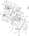
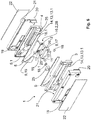
- FIG. 1 shows a fitting 1 according to the invention with a designed as a lock insert 7 lock function part, for illustrative purposes, the rear frame 19 which engages around the fitting element 4 and attachable to the rear frame 19 end cap 22 and the adjoining cover member 23 for inserting a profile cylinder, as in Fig. 6 shown in Fig. 1 not shown.
- the fitting 1 comprises a clamping area 2 (for example in FIG Fig. 2 illustrated) for a door element and has a first fitting element 3 and a second fitting element 4, which each have at least partially an abutment portion 6.1, which includes a voltage applied to the door element intermediate layer 5.
- the lock insert 7.1 is in this case designed in one piece with a third fitting element 8, which is arranged between the fitting elements 3 and 4 and can be connected to these.
- the connection between the third fitting element 8 and the fitting elements 3 and 4 via adjustment elements 9 with a head part 9.1, a connecting part 9.2 and a foot 9.3.
- the adjusting elements 9 are arranged on the connecting part 9.2 slidable in guidings 13 or feasible, which are configured on the fitting element 4.
- the scenes 13 extend between the fitting elements 3 and 4 at least in sections via the free space 6, which is designed as a receiving region between the fitting elements 3 and 4, or via the distance formed between the fitting elements 3 and 4.
- the fitting element 8 via the gate 13 with the fitting element 4 force and / or positively coupled or connectable.
- the Ein-adjusting elements 9 are inserted with the connecting part 9.2 in the slot (slot) designed backdrop 13 and attached to the headboard 9.1 by means of fasteners 11, which are here designed as screws.
- the fastening elements 11 engage through bushings 10 of the fitting element 8 into a respective bore 12 formed in the foot part 9.3 of the adjusting elements 9.
- the bore 12 is preferably designed as an internally threaded bore into which the fastening elements 11 configured as screws engage in a force-locking and / or form-fitting manner , By screwing or tightening the fasteners 11, the adjusting elements 9 are pulled in the direction of the fitting element 8 and jamming in the gate 13. D. h., That on the adjusting elements 9, the fitting element 8 non-positively and / or positively with the fitting element 4, namely in the the fitting element 4 designed backdrop 13 is connected. Since the adjusting elements 9 are displaceably guided or mounted in the slot 13 of the fitting element 4, the fitting elements 3 and 4 of the glass thickness of a door element can be adapted to each other, without the thickness of the intermediate layer 5 having to be changed.
- the material thickness of the intermediate layer 5 always remains constant, so that the distance between the fitting elements 3 and 4 to the door element, and thus the flush Connection of the fitting elements 3 and 4 encompassing frame 19, in particular the flush connection of the edge 20 designed on the edge 21 is maintained on the door element, regardless of the glass thickness of the door element.
- adjusting elements 9 is also connected to the fitting element 8 lock insert 7.1 if necessary, and as far as the installation situation of the fitting 1 according to the invention on a door element, in particular a glass door element allowed, centered to the door leaf thickness of the door element and preferably centered to the glass thickness of the glass door element , In this way, preferably a homogeneous appearance between the lock insert 7.1 and the door panels used for the door element and in particular the glass panes used for the glass door element can be adjusted.
- a lower rosette 24 is attached or attached, the present, as well as the fitting elements 3 and 4 have a cutout in the form of a profile cylinder, the cut-out designed for the lock insert 7.1 a profile cylinder is adjusted.
- the lower rosette 24 engages through the frame 19 and through the end cap 22 and is gripped on the connection cap 22 by a cover element 23, in the present case by a rosette. Also designed as a rosette cover 23 has a cutout for a profile cylinder.
- the length of the profile cylinder is to be selected or adjusted to the length of the door leaf thickness of the door element, in particular to the glass thickness of the clamped between the fitting elements 3 and 4 glass door element.
- the fitting element 8 has a recess 15 for carrying out a functional element of the lock insert 7.1 designed as a mounting module 27, on which, for example, a bolt can be mounted.
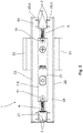
- FIG. 2 shows the in FIG. 1 shown components of a fitting 1 according to the invention in an assembled state in a front view.
- the fitting element 8 is designed in one piece with the lock insert 7 designed as a lock function part 7, which is not visible here due to the representation behind the fitting element 8.
- the fastening elements 11, which connect the fitting element 8 with the adjusting elements 9, are arranged accessible to a user from the outside.
- the fastening elements 11 designed as screws bear their screw head in an end or stop position on the fitting element 8, as a result of which the adjustment elements 9 are at least positively coupled in the scenes 13 of the fitting element 4.
- a mark A configured on the link 13 can be seen.
- the frame 19 overlaps on both sides at least in sections, here in the illustration above and below the fitting element 8. If the clamping area 2 is increased, ie widened the distance between the fitting elements 3 and 4 , thus, the arranged on both sides of the fitting elements 3 and 4 frame 19, each encompass the fitting elements 3 and 4, spaced from each other and thereby reduces the sections covering the edge 20 of the frame 19 on the fitting element 8, so that larger expectant clamping area 2 and a larger area of the fitting element 8 released. By the spacing of the frame 19 with the fitting elements 3 and 4 while a larger area of the mark A is released.
- FIG. 3 is the structure of a fitting 1, as already in the FIG. 1 shown, shown.
- fitting 1 not for receiving a profile cylinder, but for receiving a round cylinder in the fitting 1.
- the cover 23, namely the rosette which rests on the end caps 22, replaced. All other components remain as in the embodiment of the fitting 1 for receiving a profile cylinder, as in FIG. 1 shown, received.
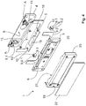
- FIG. 4 is designed as a counter lock box lock function part in a fitting 1 according to the invention.
- a fitting element 8 designed as a plate or striking plate with a recess 15 is arranged between the fitting elements 3 and 4.
- the recess 15 serves, for example, to perform a bolt when clamped to a glass wing door element or to receive the bolt between the fitting elements in the space formed by the glass cutout and by the fitting elements 6 of the designed as a counter lock box fitting 1.
- it requires for the design of the fitting 1 as a counter lock case no other fitting elements 3 and 4 in comparison to the in FIG. 1 and 3
- Only the end caps 22 differ from those in the FIGS. 1 and 3 shown fittings 1, namely the fact that they have no window and attached to the frame 19 end caps 22, the fitting elements 3 and 4 cover full-surface.
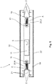
- FIG. 5 shows the configured as a counter lock case fitting 1 FIG. 4 in the assembled state.
- the recess 15 allows a view into the free space 6 designed as a receiving area between the fitting elements 3 and 4.
- FIG. 6 shows a fitting 1 according to the invention, which is designed as a corner fitting with a trained as a counter lock box lock function part.
- the fitting elements 3 and 4 are each encompassed by a frame 19, to each of which an end cap 22 is attached. Since the fitting elements 3 and 4 are preferably made of a metal, a metal alloy or also, for example, a plastic metal alloy, an abutment section 6.1, which serves to abut a door element on the fitting elements 3 and 4, comprises an intermediate layer 5 for each fitting element 3 and 4. Since the door element is preferably a glass door element, serves the intermediate layer 5 on the one hand, to prevent a system of metal on glass. On the other hand, the intermediate layers 5 support the damping properties of the fitting 1 according to the invention.
- a holder 25 is provided in each case, which serve for the arrangement, ie for the insertion of exchangeable spacer elements 18 and 18.1.
- the holder 25 is a recess in the form of a blind hole, which serves for the at least positive reception or arrangement of the spacer element 18.
- the holder 25 shown for the fitting element 3 for the spacer element 18.1 is designed as a separate component which engages, for example, in a bore, in particular in a ausgestaltetes on the fitting element blind hole 3 or in this is inserted.
- the holder 25 of the fitting element 3 also has, like the holder 25 of the fitting element 4, a recess which serves for the insertion or for the positive connection with the exchangeable spacer element 18 or 18.1.
- the fitting element 8 is designed as a connecting element 17, which is operatively connected to the holding element 16 and together form an adjusting mechanism, which from a fixing state in a dissolved Condition and vice versa is feasible.
- the connecting element 17 via two Adjustment or fastening elements 11 non-positively and / or positively connected to the support member 16.
- the holding element 16, which is in operative connection as the connecting element 17, is guided in the fitting element 3 and the fitting element 4 in a slotted guide 13, which is configured as a free space 13. 1 in the form of a recess 14, here as a groove.
- the recess 14 or the backdrop 13 configured as a free space 13 is configured parallel to the longitudinal extent of the fitting elements 3 and 4.
- the fitting element 8 configured with the retaining element 16 as a connecting element 17 is advantageously displaceable parallel to the longitudinal extension of the fitting elements with the adjusting element 9 designed as a retaining element 16. Accordingly, the fitting element 8 is also perpendicular to the longitudinal extension of the fitting elements in the space formed as a free space 6 between the fitting elements 3 and 4 movable.
- the fitting element 8, in particular its recess 15, can be adjusted to a latch engaging therein.
- the connecting element 17 is fixed in its position by means of at least non-positive with fitting elements 3 and 4 to the fitting elements 3 and 4 via the holding element 16.
- connection 9 For force and / or positive connection between the designed as a connecting element 17 fitting element 8 and configured as a holding member 16 adjustment 9 serve, as described, fasteners 11 and advantageously screws, which designed by in the fitting element 8, 17 bushings 10 in the form of Holes 12 are performed.
- the passages 10 or holes 12 are advantageously designed as internally threaded holes into which the fasteners 11, after performing through the bushings 10 form fit and / or non-positively engage.
- the holding element 16 and the connecting element 17 are in the present case designed as two interconnected components which comprise a fastening mechanism or the adjusting mechanism, which is presently integrated in both components, namely in the holding element 16 and the connecting element 17.
- a fastening mechanism or the adjusting mechanism which is presently integrated in both components, namely in the holding element 16 and the connecting element 17.
- pin 28 are configured on the connecting part.
- the pins 28 each have a bore 12 through which engage the fasteners 11 which are guided in the bushings 10, and thereby the fitting element 8, namely here, as shown, the connecting element 17 with the holding element 16 force and / or connect positively.
- the head part 16. 1 of the holding element 16 which is perpendicular to the connecting part 16. 2 has at least one and in each case, to the left and right of the connecting part 16. 2, a bearing surface which serves to fix the holding element 16 in the connecting link 3 and 4 as groove 13 or .
- the support surface of the head part 16.1 a corrugation, for example, a diamond-shaped corrugation, which engages in a configured in the scenes 13 corrugation, so that between the Holding element 16 and the fitting elements 3 and 4 in addition to the non-positive connection and a positive connection in the fixing state of the setting or fastening mechanism is formed.
- This embodiment of the support member 16 is of course also in the FIGS. 1 to 5 illustrated embodiments, but in particular then guided in the link 13 connecting part 16.2 of the support member 16, for example, has a corrugation.
- the maximum glass thickness of the clamped in the fitting 1 door element and thus the setting of the clamping area 2 on the sheet thickness of a door member by the bearing surface of the head part 16.2 of the support member 16 is limited, as these, as described above, is guided in the designed as recesses 14 scenes 13 of the fitting elements 3 and 4 and with the recesses 14 via the fastening elements 11, which connect the holding member 16 with the connecting element 17 designed as a fitting element 8, non-positively and / or positively coupled.
- FIG. 7 shows the fitting 1 according to the invention FIG. 6 in assembled state in a frontal view.
- a connecting element 17 fitting element 8 which has a recess 15 for receiving a bolt between the Be-stop elements 3 and 4 with the support member 16 at least partially, here in the figure to the left and to the right, ie displaceable parallel to the fitting elements 3 and 4.
- the fitting 1 embodied here as a counter-lock box is clamped, for example, to a vertical edge of a door element, the recess 15 that is configured in the fitting element 8, 17 can be adjusted in height-variable manner to the engagement of a bolt via the displaceability of the retaining element 16 and the fitting element 8, 17 operatively connected thereto ,
- a counter lock box which is adjustable, ie adjustable in height here in particular on the vertical edge of a door.
- FIG. 8 shows a detailed view of the section A of FIGS. 1 to 5 .
- the detail view A is the designed on the backdrop 13 marker.
- the marking shows indications in the millimeter range, and here preferably information on standardized glass door thicknesses.
- the fitting 1 according to the invention can thus be preset to the known door leaf thicknesses, in particular glass thicknesses of glass door elements.
Landscapes
- Engineering & Computer Science (AREA)
- Structural Engineering (AREA)
- Securing Of Glass Panes Or The Like (AREA)
- Road Signs Or Road Markings (AREA)
- Steering Control In Accordance With Driving Conditions (AREA)
- Traffic Control Systems (AREA)
Claims (14)
- Ferrure (1) avec une partie fonctionnelle de serrure (7), tout particulièrement un insert de serrure (7.1) ou boîtier de serrure ou têtière, avec une région de serrage (2) pour un élément de porte, tout particulièrement pour un élément de porte en verre, comprenant un premier élément de ferrure (3) et un deuxième élément de ferrure (4), lesquels comprennent respectivement au moins par régions une section d'appui (6.1), laquelle comporte une couche intermédiaire (5) pouvant établir un contact avec l'élément de porte, les éléments de ferrure (3, 4) délimitant la région de serrage (2), la partie fonctionnelle de serrure (7) comprenant un troisième élément de ferrure (8), lequel est agencé entre les éléments de ferrure (3, 4),
caractérisée en ce
que, entre les éléments de ferrure (3, 4) est prévu un mécanisme de réglage, au moyen duquel un alignement de position de la partie fonctionnelle de serrure (7) par rapport aux éléments de ferrure (3, 4) est exécutable,
le mécanisme de réglage étant aménagé de telle façon entre les éléments de ferrure (3, 4) qu'un mouvement de la partie fonctionnelle de serrure (7) peut être effectué orthogonalement par rapport à l'extension longitudinale des éléments de ferrure (3, 4) pour réaliser l'alignement de position, ou un mouvement de la partie fonctionnelle de serrure (7) peut être effectué parallèlement par rapport à l'extension longitudinale des éléments de ferrure (3, 4) pour réaliser l'alignement de position, le mécanisme de réglage comprenant au moins une coulisse (13) qui est agencée sur l'élément de ferrure (3, 4), la partie fonctionnelle de serrure (7) étant déplaçable le long de cette coulisse (13) par l'intermédiaire d'un élément de réglage (9). - Ferrure (1) selon la revendication 1,
caractérisée en ce
que les éléments de ferrure (3, 4) sont adaptés de telle façon que des épaisseurs de matière différentes de l'élément de porte peuvent être insérées dans la région de serrage (2), tout particulièrement sans avoir à modifier l'épaisseur de matière de la couche intermédiaire (5). - Ferrure (1) selon l'une des revendications précédentes,
caractérisée en ce
que la coulisse (13) forme un composant structurel commun avec au moins un élément de ferrure (3, 4), tout particulièrement en ce que la coulisse (13) et l'élément de ferrure (3, 4) sont intégraux et/ou forment un composant structurel monolithique. - Ferrure (1) selon l'une des revendications précédentes,
caractérisée en ce
que l'élément de réglage (9) est aménagé comme un élément de retenue (16), lequel relie la partie fonctionnelle de serrure (7) à au moins un élément de ferrure (3, 4), et l'élément de retenue (16) est supporte de façon mobile dans la coulisse (13). - Ferrure (1) selon l'une des revendications précédentes,
caractérisée en ce
que la coulisse (13) comporte une entaille (14) comme espace libre (13.1) en forme d'une fente ou d'une rainure, à travers laquelle ou dans laquelle l'élément de réglage (9) et/ou l'élément de retenue (16) sont mobiles/est mobile. - Ferrure (1) selon l'une des revendications précédentes,
caractérisée en ce
que l'élément de réglage (9) et/ou l'élément de retenue (16) sont affixés/est affixé sur la partie fonctionnelle de serrure (7) et/ou sur le troisième élément de ferrure (8). - Ferrure (1) selon l'une des revendications précédentes,
caractérisée en ce
que la coulisse (13) est aménagée comme une entaille (14) dans au moins un des éléments de ferrure (3, 4). - Ferrure (1) selon l'une des revendications précédentes,
caractérisée en ce
que le troisième élément de ferrure (8) et la partie fonctionnelle de serrure (7) sont aménagés comme composant structurel monolithique et/ou intégral. - Ferrure (1) selon l'une des revendications précédentes,
caractérisée en ce
que la troisième élément de ferrure (8) comprend au moins un évidement (15) pour le passage et/ou l'engagement d'un élément fonctionnel d'une serrure. - Ferrure (1) selon l'une des revendications précédentes,
caractérisée en ce
l'élément de retenue (16) est en connexion opérationnelle avec un troisième élément de ferrure (8) aménagé comme élément de connexion (17), sur lequel est aménagé l'évidement (15) pour l'engagement d'un élément fonctionnel, tout particulièrement d'un pêne dormant. - Ferrure (1) selon l'une des revendications précédentes,
caractérisée en ce
que l'élément de réglage (9) et l'élément de retenue (16) comprennent une partie de tête (9.1, 16.1), une partie de connexion (9.2, 16.2), et en option une partie de base (9.3), l'élément de connexion (17) étant affixé sur la partie de connexion (16.2) par l'intermédiaire d'au moins un élément de fixation (11), et tout particulièrement la partie de tête (9.1, 16.1) et la partie de connexion (9.2, 16.2) étant alignées verticalement l'une par rapport à l'autre et la partie de base (9.3) parallèlement par rapport à la partie de tête (9.1) et/ou forment un composant structurel monolithique et/ou intégral. - Ferrure (1) selon l'une des revendications précédentes,
caractérisée en ce
que l'élément de retenue (16) est déplaçable le long de l'extension longitudinale de l'élément de ferrure (3, 4) par l'intermédiaire de la partie de connexion (16.2) dans un espace libre (6), l'espace libre (6) étant aménagé de telle façon par rapport à l'élément de retenue (16) que l'élément de retenue (16) est déplaçable orthogonalement par rapport à la première direction de mouvement vers une deuxième direction de mouvement. - Ferrure (1) selon l'une des revendications précédentes,
caractérisée en ce
que ledit au moins un élément de distance (18, 18.1) échangeable est agencé entre les éléments de ferrure (3, 4) à l'extérieur des sections d'appui (6.1), tout particulièrement l'élément de distance (18, 18.1) étant aménagé comme contre-palier aux sections d'appui (6.1) et à l'élément de porte qui est serré dans la région de serrage (2). - Ferrure (1) selon l'une des revendications précédentes,
caractérisée en ce
que le mécanisme de réglage comporte l'élément de réglage (9) et/ou l'élément de retenue (16).
Priority Applications (4)
| Application Number | Priority Date | Filing Date | Title |
|---|---|---|---|
| EP14196240.7A EP3029227B2 (fr) | 2014-12-04 | 2014-12-04 | Ferrure dotée d'une plage de serrage réglable |
| ES14196240T ES2684991T5 (es) | 2014-12-04 | 2014-12-04 | Herraje con zona de sujeción ajustable |
| CN201510324524.0A CN105672816B (zh) | 2014-12-04 | 2015-06-12 | 具有可调节的夹紧区域的包覆件 |
| US14/946,079 US11306504B2 (en) | 2014-12-04 | 2015-11-19 | Fitting with adjustable restraining area |
Applications Claiming Priority (1)
| Application Number | Priority Date | Filing Date | Title |
|---|---|---|---|
| EP14196240.7A EP3029227B2 (fr) | 2014-12-04 | 2014-12-04 | Ferrure dotée d'une plage de serrage réglable |
Publications (3)
| Publication Number | Publication Date |
|---|---|
| EP3029227A1 EP3029227A1 (fr) | 2016-06-08 |
| EP3029227B1 true EP3029227B1 (fr) | 2018-05-09 |
| EP3029227B2 EP3029227B2 (fr) | 2022-05-18 |
Family
ID=52103206
Family Applications (1)
| Application Number | Title | Priority Date | Filing Date |
|---|---|---|---|
| EP14196240.7A Active EP3029227B2 (fr) | 2014-12-04 | 2014-12-04 | Ferrure dotée d'une plage de serrage réglable |
Country Status (4)
| Country | Link |
|---|---|
| US (1) | US11306504B2 (fr) |
| EP (1) | EP3029227B2 (fr) |
| CN (1) | CN105672816B (fr) |
| ES (1) | ES2684991T5 (fr) |
Families Citing this family (2)
| Publication number | Priority date | Publication date | Assignee | Title |
|---|---|---|---|---|
| ES2567927B1 (es) * | 2014-09-26 | 2017-01-31 | Ojmar, S.A. | Cerradura con sistema de amarre mejorado |
| US11248398B2 (en) * | 2018-01-23 | 2022-02-15 | Hanchett Entry Systems, Inc. | Patch lock assembly |
Citations (16)
| Publication number | Priority date | Publication date | Assignee | Title |
|---|---|---|---|---|
| US887817A (en) | 1906-04-10 | 1908-05-19 | Henry Francis Keil | Lock. |
| US2178132A (en) | 1938-08-13 | 1939-10-31 | Norman F Anderson | Lock |
| GB937563A (en) | 1961-09-08 | 1963-09-25 | Walter Rowley Ltd | Means for mounting fastenings in glass doors and the like |
| US3702549A (en) | 1970-10-22 | 1972-11-14 | George B Solovieff | High security door lock |
| DE2205092A1 (de) | 1972-02-03 | 1973-08-16 | Berchtold Ag | Tuerschloss mit riegel |
| DE2541026B1 (de) | 1975-09-15 | 1977-01-20 | Schlechtendahl & Soehne Wilh | Beschlag fuer einen ganzglasfluegel eines fensters oder einer tuer |
| US4171836A (en) | 1978-05-10 | 1979-10-23 | Lst Corporation | Security strike plate assembly |
| DE2903635A1 (de) | 1979-01-31 | 1980-08-14 | Westfaelisches Metallwerk | Tuerbeschlag |
| EP0220363B1 (fr) | 1985-10-25 | 1989-06-07 | SOCIETA' ITALIANA PROGETTI S.r.l. | Ferrure pour un panneau entièrement vitré, en particulier pour portes, fenêtres, fenêtres à tabatière et vitrines |
| DE4300810A1 (de) | 1993-01-14 | 1994-07-21 | Italiana Progetti | Riegelschloß für eine Ganzglastür |
| DE9402472U1 (de) | 1994-02-15 | 1995-06-14 | Società Italiana Progetti S.r.l., Magenta, Mailand/Milano | Verriegelungsbeschlag und Scheinbeschlag für Ganzglasschiebetürflügel oder -Rollwandelemente |
| US6381909B1 (en) | 2000-09-13 | 2002-05-07 | Shou-Hsing Liao | Corner transom fitting for frameless tempered glass door |
| DE202005015457U1 (de) | 2005-09-26 | 2007-02-15 | Krimmel, Maria | Ganzglastür und Schloss für Ganzglastür |
| US20080093520A1 (en) | 2006-10-19 | 2008-04-24 | Door & Window Hardware Co. | Frameless glass door clamp |
| EP2163716A2 (fr) | 2008-09-12 | 2010-03-17 | Raumplus Gmbh & Co. Kg | Verrou pour une porte coulissante |
| DE102009022803A1 (de) | 2009-05-27 | 2010-12-02 | Dorma Gmbh + Co. Kg | Dreiteiliger Universaltürbeschlag |
Family Cites Families (30)
| Publication number | Priority date | Publication date | Assignee | Title |
|---|---|---|---|---|
| US365152A (en) * | 1887-06-21 | simson | ||
| US839556A (en) * | 1906-03-22 | 1906-12-25 | Morris Harris | Lock-strike. |
| US1250650A (en) * | 1917-08-16 | 1917-12-18 | Campbell Jobes | Lock-strike. |
| US2153080A (en) * | 1937-02-26 | 1939-04-04 | Flora Mfg Company Inc | Adjustable lock strike |
| US2572428A (en) * | 1948-09-28 | 1951-10-23 | James W Anstine | Adjustable lock keeper |
| US2952150A (en) * | 1956-07-23 | 1960-09-13 | Matzkin Harry | Glass door locking construction |
| US3107113A (en) * | 1961-05-17 | 1963-10-15 | Sconzo Thomas George | Adjustable door latch assembly |
| FR1500507A (fr) * | 1966-03-11 | 1967-11-03 | Vetreria Di Vernante Spa | Assemblage de serrure et poignées pour des portes en verre trempé et similaires |
| GB1247848A (en) * | 1967-11-15 | 1971-09-29 | Tonks Birmingham Ltd | Door or panel fittings |
| CH599437A5 (en) * | 1975-10-06 | 1978-05-31 | Schliesstech Anst | Misalignment correcting lock bolt abutment |
| US4456290A (en) * | 1983-01-03 | 1984-06-26 | Brite-Vue Glass Systems, Inc. | Mounting hardware assembly for glass door cutouts |
| EP0209845A3 (fr) * | 1985-07-18 | 1987-07-29 | Hans Joachim Solbach | Ferrure pour portes faites entièrement en verre ou analogues |
| US4873853A (en) * | 1989-03-23 | 1989-10-17 | Best Lock Corporation | Escutcheon assembly |
| US5322333A (en) † | 1992-10-16 | 1994-06-21 | Emhart Inc. | Cylindrical lockset |
| GB2282842A (en) * | 1993-10-13 | 1995-04-19 | Shieh Jin Ren | Adjustable door bolt. |
| US5533368A (en) † | 1995-03-06 | 1996-07-09 | Schlage Lock Company | Means for, and a method of, adjusting a cylindrical lockset for door thickness-sizing |
| US6058746A (en) * | 1998-08-07 | 2000-05-09 | Emhart Inc. | Adjustable interconnected lock |
| CN2440101Y (zh) * | 2000-07-21 | 2001-07-25 | 好信有限公司 | 无框式玻璃门的上包角 |
| KR100487073B1 (ko) * | 2001-10-16 | 2005-05-03 | 가부시키가이샤 니프코 | 유리홀더 및 유리장착방법 |
| CN2727352Y (zh) * | 2004-07-16 | 2005-09-21 | 张鸿联 | 新型玻璃门具结构 |
| US7588272B2 (en) * | 2005-01-07 | 2009-09-15 | National Manufacturing Co. | Door handle assembly |
| TW200815654A (en) * | 2006-09-21 | 2008-04-01 | Door & Amp Window Hardware Co | Locking device for frameless glass door |
| US7971394B1 (en) * | 2007-01-19 | 2011-07-05 | Michael T Dowling | Adjustable lock height door |
| US20100050707A1 (en) * | 2008-08-29 | 2010-03-04 | Shou-Hsing Liao | Frameless glass door lock |
| CH700306A1 (de) * | 2009-01-22 | 2010-07-30 | Pilz Auslandsbeteiligungen Gmb | Verriegelungseinrichtung. |
| DE102009022802A1 (de) † | 2009-05-27 | 2010-12-02 | Dorma Gmbh + Co. Kg | Schwenkwinkeltoleranzausgleichsbeschlag für eine Pendeltür |
| CN201546561U (zh) * | 2009-10-13 | 2010-08-11 | 邹忠 | 一种玻璃门扇安装液动自控夹 |
| EP2817522B1 (fr) * | 2012-02-22 | 2017-11-29 | Jose Teixeira Mao-Cheia | Bride pour panneau de verre |
| EP3029240A1 (fr) * | 2014-12-04 | 2016-06-08 | DORMA Deutschland GmbH | Ferrure d'angle dotée d'une plage de réglage variable |
| EP3029238B1 (fr) * | 2014-12-04 | 2021-09-08 | dormakaba Deutschland GmbH | Ferrure d'angle dotée d'une plage de serrage réglable |
-
2014
- 2014-12-04 ES ES14196240T patent/ES2684991T5/es active Active
- 2014-12-04 EP EP14196240.7A patent/EP3029227B2/fr active Active
-
2015
- 2015-06-12 CN CN201510324524.0A patent/CN105672816B/zh not_active Expired - Fee Related
- 2015-11-19 US US14/946,079 patent/US11306504B2/en active Active
Patent Citations (16)
| Publication number | Priority date | Publication date | Assignee | Title |
|---|---|---|---|---|
| US887817A (en) | 1906-04-10 | 1908-05-19 | Henry Francis Keil | Lock. |
| US2178132A (en) | 1938-08-13 | 1939-10-31 | Norman F Anderson | Lock |
| GB937563A (en) | 1961-09-08 | 1963-09-25 | Walter Rowley Ltd | Means for mounting fastenings in glass doors and the like |
| US3702549A (en) | 1970-10-22 | 1972-11-14 | George B Solovieff | High security door lock |
| DE2205092A1 (de) | 1972-02-03 | 1973-08-16 | Berchtold Ag | Tuerschloss mit riegel |
| DE2541026B1 (de) | 1975-09-15 | 1977-01-20 | Schlechtendahl & Soehne Wilh | Beschlag fuer einen ganzglasfluegel eines fensters oder einer tuer |
| US4171836A (en) | 1978-05-10 | 1979-10-23 | Lst Corporation | Security strike plate assembly |
| DE2903635A1 (de) | 1979-01-31 | 1980-08-14 | Westfaelisches Metallwerk | Tuerbeschlag |
| EP0220363B1 (fr) | 1985-10-25 | 1989-06-07 | SOCIETA' ITALIANA PROGETTI S.r.l. | Ferrure pour un panneau entièrement vitré, en particulier pour portes, fenêtres, fenêtres à tabatière et vitrines |
| DE4300810A1 (de) | 1993-01-14 | 1994-07-21 | Italiana Progetti | Riegelschloß für eine Ganzglastür |
| DE9402472U1 (de) | 1994-02-15 | 1995-06-14 | Società Italiana Progetti S.r.l., Magenta, Mailand/Milano | Verriegelungsbeschlag und Scheinbeschlag für Ganzglasschiebetürflügel oder -Rollwandelemente |
| US6381909B1 (en) | 2000-09-13 | 2002-05-07 | Shou-Hsing Liao | Corner transom fitting for frameless tempered glass door |
| DE202005015457U1 (de) | 2005-09-26 | 2007-02-15 | Krimmel, Maria | Ganzglastür und Schloss für Ganzglastür |
| US20080093520A1 (en) | 2006-10-19 | 2008-04-24 | Door & Window Hardware Co. | Frameless glass door clamp |
| EP2163716A2 (fr) | 2008-09-12 | 2010-03-17 | Raumplus Gmbh & Co. Kg | Verrou pour une porte coulissante |
| DE102009022803A1 (de) | 2009-05-27 | 2010-12-02 | Dorma Gmbh + Co. Kg | Dreiteiliger Universaltürbeschlag |
Also Published As
| Publication number | Publication date |
|---|---|
| ES2684991T3 (es) | 2018-10-05 |
| CN105672816B (zh) | 2019-10-01 |
| ES2684991T5 (es) | 2022-10-11 |
| EP3029227B2 (fr) | 2022-05-18 |
| US20160194899A1 (en) | 2016-07-07 |
| CN105672816A (zh) | 2016-06-15 |
| EP3029227A1 (fr) | 2016-06-08 |
| US11306504B2 (en) | 2022-04-19 |
Similar Documents
| Publication | Publication Date | Title |
|---|---|---|
| EP2715021B1 (fr) | Scharnière | |
| EP1606485B1 (fr) | Ferrure | |
| EP3102759B1 (fr) | Ferrure d'un battant de fenêtres ou de portes, au moins relevable et coulissant | |
| DE102007028218B3 (de) | Tür- oder Fensterscharnier | |
| EP2366857B1 (fr) | Agencement de fixation pour une porte coulissante | |
| DE10106218C1 (de) | Fensterladen mit wenigstens zwei Befestigungsbändern | |
| EP2113624B1 (fr) | Dispositif de fixation de porte ou de fenêtre | |
| EP2213825B1 (fr) | Barre de dormant d'un dormant de portes ou de portails dotés d'un dispositif de fixation | |
| EP3029227B1 (fr) | Ferrure dotée d'une plage de serrage réglable | |
| DE202012105001U1 (de) | Türsystem | |
| DE202007011076U1 (de) | Bandanordnung mit Führungsprofil | |
| DE9407569U1 (de) | Einbruchsicherung | |
| DE29620246U1 (de) | Band für Türen oder Fenster | |
| EP1560996B1 (fr) | Systeme d'armatures pour portes en verre | |
| DE102021115490B4 (de) | Feststellvorrichtung für beidseitig angeschlagene Tür | |
| DE29904129U1 (de) | Verschwindscharnier | |
| EP3029240A1 (fr) | Ferrure d'angle dotée d'une plage de réglage variable | |
| EP3029236B1 (fr) | Ferrure d'angle réglable dotée d'un élément de retenue | |
| DE202017105083U1 (de) | Türband mit Flügelstabilisierung | |
| DE102007025857A1 (de) | Gelenkband für Türen oder Fenster | |
| EP1659246A1 (fr) | Charnière pour volets | |
| DE112021004078T5 (de) | Verdecktes scharnier zum öffnen von fenstern und türen | |
| DE20120613U1 (de) | Scharnier | |
| DE29600891U1 (de) | Sicherungseinrichtung | |
| DE19918283B4 (de) | Tür- oder Fensterdrehband |
Legal Events
| Date | Code | Title | Description |
|---|---|---|---|
| PUAI | Public reference made under article 153(3) epc to a published international application that has entered the european phase |
Free format text: ORIGINAL CODE: 0009012 |
|
| AK | Designated contracting states |
Kind code of ref document: A1 Designated state(s): AL AT BE BG CH CY CZ DE DK EE ES FI FR GB GR HR HU IE IS IT LI LT LU LV MC MK MT NL NO PL PT RO RS SE SI SK SM TR |
|
| AX | Request for extension of the european patent |
Extension state: BA ME |
|
| STAA | Information on the status of an ep patent application or granted ep patent |
Free format text: STATUS: REQUEST FOR EXAMINATION WAS MADE |
|
| 17P | Request for examination filed |
Effective date: 20161207 |
|
| RAP1 | Party data changed (applicant data changed or rights of an application transferred) |
Owner name: DORMAKABA DEUTSCHLAND GMBH |
|
| RBV | Designated contracting states (corrected) |
Designated state(s): AL AT BE BG CH CY CZ DE DK EE ES FI FR GB GR HR HU IE IS IT LI LT LU LV MC MK MT NL NO PL PT RO RS SE SI SK SM TR |
|
| GRAP | Despatch of communication of intention to grant a patent |
Free format text: ORIGINAL CODE: EPIDOSNIGR1 |
|
| STAA | Information on the status of an ep patent application or granted ep patent |
Free format text: STATUS: GRANT OF PATENT IS INTENDED |
|
| INTG | Intention to grant announced |
Effective date: 20171129 |
|
| GRAS | Grant fee paid |
Free format text: ORIGINAL CODE: EPIDOSNIGR3 |
|
| GRAA | (expected) grant |
Free format text: ORIGINAL CODE: 0009210 |
|
| STAA | Information on the status of an ep patent application or granted ep patent |
Free format text: STATUS: THE PATENT HAS BEEN GRANTED |
|
| AK | Designated contracting states |
Kind code of ref document: B1 Designated state(s): AL AT BE BG CH CY CZ DE DK EE ES FI FR GB GR HR HU IE IS IT LI LT LU LV MC MK MT NL NO PL PT RO RS SE SI SK SM TR |
|
| REG | Reference to a national code |
Ref country code: GB Ref legal event code: FG4D Free format text: NOT ENGLISH |
|
| REG | Reference to a national code |
Ref country code: CH Ref legal event code: EP Ref country code: AT Ref legal event code: REF Ref document number: 997700 Country of ref document: AT Kind code of ref document: T Effective date: 20180515 |
|
| REG | Reference to a national code |
Ref country code: IE Ref legal event code: FG4D Free format text: LANGUAGE OF EP DOCUMENT: GERMAN |
|
| REG | Reference to a national code |
Ref country code: DE Ref legal event code: R096 Ref document number: 502014008202 Country of ref document: DE |
|
| REG | Reference to a national code |
Ref country code: CH Ref legal event code: NV Representative=s name: RENTSCH PARTNER AG, CH |
|
| REG | Reference to a national code |
Ref country code: NL Ref legal event code: MP Effective date: 20180509 |
|
| REG | Reference to a national code |
Ref country code: LT Ref legal event code: MG4D |
|
| REG | Reference to a national code |
Ref country code: ES Ref legal event code: FG2A Ref document number: 2684991 Country of ref document: ES Kind code of ref document: T3 Effective date: 20181005 |
|
| PG25 | Lapsed in a contracting state [announced via postgrant information from national office to epo] |
Ref country code: SE Free format text: LAPSE BECAUSE OF FAILURE TO SUBMIT A TRANSLATION OF THE DESCRIPTION OR TO PAY THE FEE WITHIN THE PRESCRIBED TIME-LIMIT Effective date: 20180509 Ref country code: FI Free format text: LAPSE BECAUSE OF FAILURE TO SUBMIT A TRANSLATION OF THE DESCRIPTION OR TO PAY THE FEE WITHIN THE PRESCRIBED TIME-LIMIT Effective date: 20180509 Ref country code: NO Free format text: LAPSE BECAUSE OF FAILURE TO SUBMIT A TRANSLATION OF THE DESCRIPTION OR TO PAY THE FEE WITHIN THE PRESCRIBED TIME-LIMIT Effective date: 20180809 Ref country code: BG Free format text: LAPSE BECAUSE OF FAILURE TO SUBMIT A TRANSLATION OF THE DESCRIPTION OR TO PAY THE FEE WITHIN THE PRESCRIBED TIME-LIMIT Effective date: 20180809 Ref country code: LT Free format text: LAPSE BECAUSE OF FAILURE TO SUBMIT A TRANSLATION OF THE DESCRIPTION OR TO PAY THE FEE WITHIN THE PRESCRIBED TIME-LIMIT Effective date: 20180509 |
|
| PG25 | Lapsed in a contracting state [announced via postgrant information from national office to epo] |
Ref country code: HR Free format text: LAPSE BECAUSE OF FAILURE TO SUBMIT A TRANSLATION OF THE DESCRIPTION OR TO PAY THE FEE WITHIN THE PRESCRIBED TIME-LIMIT Effective date: 20180509 Ref country code: NL Free format text: LAPSE BECAUSE OF FAILURE TO SUBMIT A TRANSLATION OF THE DESCRIPTION OR TO PAY THE FEE WITHIN THE PRESCRIBED TIME-LIMIT Effective date: 20180509 Ref country code: LV Free format text: LAPSE BECAUSE OF FAILURE TO SUBMIT A TRANSLATION OF THE DESCRIPTION OR TO PAY THE FEE WITHIN THE PRESCRIBED TIME-LIMIT Effective date: 20180509 Ref country code: GR Free format text: LAPSE BECAUSE OF FAILURE TO SUBMIT A TRANSLATION OF THE DESCRIPTION OR TO PAY THE FEE WITHIN THE PRESCRIBED TIME-LIMIT Effective date: 20180810 Ref country code: RS Free format text: LAPSE BECAUSE OF FAILURE TO SUBMIT A TRANSLATION OF THE DESCRIPTION OR TO PAY THE FEE WITHIN THE PRESCRIBED TIME-LIMIT Effective date: 20180509 |
|
| PG25 | Lapsed in a contracting state [announced via postgrant information from national office to epo] |
Ref country code: CZ Free format text: LAPSE BECAUSE OF FAILURE TO SUBMIT A TRANSLATION OF THE DESCRIPTION OR TO PAY THE FEE WITHIN THE PRESCRIBED TIME-LIMIT Effective date: 20180509 Ref country code: RO Free format text: LAPSE BECAUSE OF FAILURE TO SUBMIT A TRANSLATION OF THE DESCRIPTION OR TO PAY THE FEE WITHIN THE PRESCRIBED TIME-LIMIT Effective date: 20180509 Ref country code: EE Free format text: LAPSE BECAUSE OF FAILURE TO SUBMIT A TRANSLATION OF THE DESCRIPTION OR TO PAY THE FEE WITHIN THE PRESCRIBED TIME-LIMIT Effective date: 20180509 Ref country code: PL Free format text: LAPSE BECAUSE OF FAILURE TO SUBMIT A TRANSLATION OF THE DESCRIPTION OR TO PAY THE FEE WITHIN THE PRESCRIBED TIME-LIMIT Effective date: 20180509 Ref country code: DK Free format text: LAPSE BECAUSE OF FAILURE TO SUBMIT A TRANSLATION OF THE DESCRIPTION OR TO PAY THE FEE WITHIN THE PRESCRIBED TIME-LIMIT Effective date: 20180509 Ref country code: SK Free format text: LAPSE BECAUSE OF FAILURE TO SUBMIT A TRANSLATION OF THE DESCRIPTION OR TO PAY THE FEE WITHIN THE PRESCRIBED TIME-LIMIT Effective date: 20180509 |
|
| REG | Reference to a national code |
Ref country code: DE Ref legal event code: R026 Ref document number: 502014008202 Country of ref document: DE |
|
| PLBI | Opposition filed |
Free format text: ORIGINAL CODE: 0009260 |
|
| PG25 | Lapsed in a contracting state [announced via postgrant information from national office to epo] |
Ref country code: SM Free format text: LAPSE BECAUSE OF FAILURE TO SUBMIT A TRANSLATION OF THE DESCRIPTION OR TO PAY THE FEE WITHIN THE PRESCRIBED TIME-LIMIT Effective date: 20180509 |
|
| PLAX | Notice of opposition and request to file observation + time limit sent |
Free format text: ORIGINAL CODE: EPIDOSNOBS2 |
|
| 26 | Opposition filed |
Opponent name: GEZE GMBH Effective date: 20190211 |
|
| PG25 | Lapsed in a contracting state [announced via postgrant information from national office to epo] |
Ref country code: SI Free format text: LAPSE BECAUSE OF FAILURE TO SUBMIT A TRANSLATION OF THE DESCRIPTION OR TO PAY THE FEE WITHIN THE PRESCRIBED TIME-LIMIT Effective date: 20180509 |
|
| PLBB | Reply of patent proprietor to notice(s) of opposition received |
Free format text: ORIGINAL CODE: EPIDOSNOBS3 |
|
| GBPC | Gb: european patent ceased through non-payment of renewal fee |
Effective date: 20181204 |
|
| PG25 | Lapsed in a contracting state [announced via postgrant information from national office to epo] |
Ref country code: MC Free format text: LAPSE BECAUSE OF FAILURE TO SUBMIT A TRANSLATION OF THE DESCRIPTION OR TO PAY THE FEE WITHIN THE PRESCRIBED TIME-LIMIT Effective date: 20180509 Ref country code: LU Free format text: LAPSE BECAUSE OF NON-PAYMENT OF DUE FEES Effective date: 20181204 |
|
| REG | Reference to a national code |
Ref country code: IE Ref legal event code: MM4A |
|
| REG | Reference to a national code |
Ref country code: BE Ref legal event code: MM Effective date: 20181231 |
|
| PG25 | Lapsed in a contracting state [announced via postgrant information from national office to epo] |
Ref country code: IE Free format text: LAPSE BECAUSE OF NON-PAYMENT OF DUE FEES Effective date: 20181204 |
|
| PG25 | Lapsed in a contracting state [announced via postgrant information from national office to epo] |
Ref country code: AL Free format text: LAPSE BECAUSE OF FAILURE TO SUBMIT A TRANSLATION OF THE DESCRIPTION OR TO PAY THE FEE WITHIN THE PRESCRIBED TIME-LIMIT Effective date: 20180509 Ref country code: BE Free format text: LAPSE BECAUSE OF NON-PAYMENT OF DUE FEES Effective date: 20181231 |
|
| PG25 | Lapsed in a contracting state [announced via postgrant information from national office to epo] |
Ref country code: GB Free format text: LAPSE BECAUSE OF NON-PAYMENT OF DUE FEES Effective date: 20181204 |
|
| PG25 | Lapsed in a contracting state [announced via postgrant information from national office to epo] |
Ref country code: MT Free format text: LAPSE BECAUSE OF FAILURE TO SUBMIT A TRANSLATION OF THE DESCRIPTION OR TO PAY THE FEE WITHIN THE PRESCRIBED TIME-LIMIT Effective date: 20180509 |
|
| PG25 | Lapsed in a contracting state [announced via postgrant information from national office to epo] |
Ref country code: TR Free format text: LAPSE BECAUSE OF FAILURE TO SUBMIT A TRANSLATION OF THE DESCRIPTION OR TO PAY THE FEE WITHIN THE PRESCRIBED TIME-LIMIT Effective date: 20180509 |
|
| PG25 | Lapsed in a contracting state [announced via postgrant information from national office to epo] |
Ref country code: PT Free format text: LAPSE BECAUSE OF FAILURE TO SUBMIT A TRANSLATION OF THE DESCRIPTION OR TO PAY THE FEE WITHIN THE PRESCRIBED TIME-LIMIT Effective date: 20180509 |
|
| PG25 | Lapsed in a contracting state [announced via postgrant information from national office to epo] |
Ref country code: CY Free format text: LAPSE BECAUSE OF FAILURE TO SUBMIT A TRANSLATION OF THE DESCRIPTION OR TO PAY THE FEE WITHIN THE PRESCRIBED TIME-LIMIT Effective date: 20180509 Ref country code: MK Free format text: LAPSE BECAUSE OF NON-PAYMENT OF DUE FEES Effective date: 20180509 Ref country code: HU Free format text: LAPSE BECAUSE OF FAILURE TO SUBMIT A TRANSLATION OF THE DESCRIPTION OR TO PAY THE FEE WITHIN THE PRESCRIBED TIME-LIMIT; INVALID AB INITIO Effective date: 20141204 |
|
| PG25 | Lapsed in a contracting state [announced via postgrant information from national office to epo] |
Ref country code: IS Free format text: LAPSE BECAUSE OF FAILURE TO SUBMIT A TRANSLATION OF THE DESCRIPTION OR TO PAY THE FEE WITHIN THE PRESCRIBED TIME-LIMIT Effective date: 20180909 |
|
| REG | Reference to a national code |
Ref country code: DE Ref legal event code: R081 Ref document number: 502014008202 Country of ref document: DE Owner name: DORMA-GLAS GMBH, DE Free format text: FORMER OWNER: DORMAKABA DEUTSCHLAND GMBH, 58256 ENNEPETAL, DE |
|
| REG | Reference to a national code |
Ref country code: ES Ref legal event code: PC2A Owner name: DORMA-GLAS GMBH Effective date: 20220303 |
|
| PUAH | Patent maintained in amended form |
Free format text: ORIGINAL CODE: 0009272 |
|
| REG | Reference to a national code |
Ref country code: AT Ref legal event code: PC Ref document number: 997700 Country of ref document: AT Kind code of ref document: T Owner name: DORMA-GLAS GMBH, DE Effective date: 20220216 |
|
| STAA | Information on the status of an ep patent application or granted ep patent |
Free format text: STATUS: PATENT MAINTAINED AS AMENDED |
|
| RAP2 | Party data changed (patent owner data changed or rights of a patent transferred) |
Owner name: DORMA-GLAS GMBH |
|
| 27A | Patent maintained in amended form |
Effective date: 20220518 |
|
| AK | Designated contracting states |
Kind code of ref document: B2 Designated state(s): AL AT BE BG CH CY CZ DE DK EE ES FI FR GB GR HR HU IE IS IT LI LT LU LV MC MK MT NL NO PL PT RO RS SE SI SK SM TR |
|
| REG | Reference to a national code |
Ref country code: DE Ref legal event code: R102 Ref document number: 502014008202 Country of ref document: DE |
|
| REG | Reference to a national code |
Ref country code: ES Ref legal event code: DC2A Ref document number: 2684991 Country of ref document: ES Kind code of ref document: T5 Effective date: 20221011 |
|
| PGFP | Annual fee paid to national office [announced via postgrant information from national office to epo] |
Ref country code: FR Payment date: 20231221 Year of fee payment: 10 Ref country code: AT Payment date: 20231221 Year of fee payment: 10 |
|
| PGFP | Annual fee paid to national office [announced via postgrant information from national office to epo] |
Ref country code: ES Payment date: 20240129 Year of fee payment: 10 |
|
| PGFP | Annual fee paid to national office [announced via postgrant information from national office to epo] |
Ref country code: CH Payment date: 20240102 Year of fee payment: 10 |
|
| REG | Reference to a national code |
Ref country code: CH Ref legal event code: PL |
|
| REG | Reference to a national code |
Ref country code: AT Ref legal event code: MM01 Ref document number: 997700 Country of ref document: AT Kind code of ref document: T Effective date: 20241204 |
|
| PG25 | Lapsed in a contracting state [announced via postgrant information from national office to epo] |
Ref country code: AT Free format text: LAPSE BECAUSE OF NON-PAYMENT OF DUE FEES Effective date: 20241204 Ref country code: FR Free format text: LAPSE BECAUSE OF NON-PAYMENT OF DUE FEES Effective date: 20241231 |
|
| PG25 | Lapsed in a contracting state [announced via postgrant information from national office to epo] |
Ref country code: CH Free format text: LAPSE BECAUSE OF NON-PAYMENT OF DUE FEES Effective date: 20241231 |
|
| PGFP | Annual fee paid to national office [announced via postgrant information from national office to epo] |
Ref country code: DE Payment date: 20251211 Year of fee payment: 12 |
|
| PGFP | Annual fee paid to national office [announced via postgrant information from national office to epo] |
Ref country code: IT Payment date: 20251223 Year of fee payment: 12 |
|
| REG | Reference to a national code |
Ref country code: ES Ref legal event code: FD2A Effective date: 20260127 |
|
| PG25 | Lapsed in a contracting state [announced via postgrant information from national office to epo] |
Ref country code: ES Free format text: LAPSE BECAUSE OF NON-PAYMENT OF DUE FEES Effective date: 20241205 |