EP3029236B1 - Ferrure d'angle réglable dotée d'un élément de retenue - Google Patents
Ferrure d'angle réglable dotée d'un élément de retenue Download PDFInfo
- Publication number
- EP3029236B1 EP3029236B1 EP14196234.0A EP14196234A EP3029236B1 EP 3029236 B1 EP3029236 B1 EP 3029236B1 EP 14196234 A EP14196234 A EP 14196234A EP 3029236 B1 EP3029236 B1 EP 3029236B1
- Authority
- EP
- European Patent Office
- Prior art keywords
- fitting
- retaining element
- recess
- retaining
- door
- Prior art date
- Legal status (The legal status is an assumption and is not a legal conclusion. Google has not performed a legal analysis and makes no representation as to the accuracy of the status listed.)
- Not-in-force
Links
- 230000007246 mechanism Effects 0.000 claims description 42
- 238000000034 method Methods 0.000 claims description 7
- 230000000284 resting effect Effects 0.000 claims 3
- 239000000853 adhesive Substances 0.000 claims 2
- 230000001070 adhesive effect Effects 0.000 claims 2
- 230000000694 effects Effects 0.000 claims 1
- 239000011521 glass Substances 0.000 description 11
- 238000006073 displacement reaction Methods 0.000 description 8
- 230000003068 static effect Effects 0.000 description 7
- 239000000463 material Substances 0.000 description 6
- 230000008901 benefit Effects 0.000 description 3
- 238000009434 installation Methods 0.000 description 2
- 238000003860 storage Methods 0.000 description 2
- QNRATNLHPGXHMA-XZHTYLCXSA-N (r)-(6-ethoxyquinolin-4-yl)-[(2s,4s,5r)-5-ethyl-1-azabicyclo[2.2.2]octan-2-yl]methanol;hydrochloride Chemical compound Cl.C([C@H]([C@H](C1)CC)C2)CN1[C@@H]2[C@H](O)C1=CC=NC2=CC=C(OCC)C=C21 QNRATNLHPGXHMA-XZHTYLCXSA-N 0.000 description 1
- 240000001439 Opuntia Species 0.000 description 1
- 235000004727 Opuntia ficus indica Nutrition 0.000 description 1
- 230000015572 biosynthetic process Effects 0.000 description 1
- 230000008878 coupling Effects 0.000 description 1
- 238000010168 coupling process Methods 0.000 description 1
- 238000005859 coupling reaction Methods 0.000 description 1
- 238000005520 cutting process Methods 0.000 description 1
- 230000001419 dependent effect Effects 0.000 description 1
- 238000005553 drilling Methods 0.000 description 1
- 238000001746 injection moulding Methods 0.000 description 1
- 238000003754 machining Methods 0.000 description 1
- 238000004519 manufacturing process Methods 0.000 description 1
- 239000002184 metal Substances 0.000 description 1
- 238000003801 milling Methods 0.000 description 1
- 230000008569 process Effects 0.000 description 1
- 230000009467 reduction Effects 0.000 description 1
- 230000000630 rising effect Effects 0.000 description 1
- 239000000243 solution Substances 0.000 description 1
Images

Classifications
-
- E—FIXED CONSTRUCTIONS
- E05—LOCKS; KEYS; WINDOW OR DOOR FITTINGS; SAFES
- E05D—HINGES OR SUSPENSION DEVICES FOR DOORS, WINDOWS OR WINGS
- E05D7/00—Hinges or pivots of special construction
- E05D7/08—Hinges or pivots of special construction for use in suspensions comprising two spigots placed at opposite edges of the wing, especially at the top and the bottom, e.g. trunnions
- E05D7/081—Hinges or pivots of special construction for use in suspensions comprising two spigots placed at opposite edges of the wing, especially at the top and the bottom, e.g. trunnions the pivot axis of the wing being situated near one edge of the wing, especially at the top and bottom, e.g. trunnions
-
- E—FIXED CONSTRUCTIONS
- E05—LOCKS; KEYS; WINDOW OR DOOR FITTINGS; SAFES
- E05D—HINGES OR SUSPENSION DEVICES FOR DOORS, WINDOWS OR WINGS
- E05D5/00—Construction of single parts, e.g. the parts for attachment
- E05D5/02—Parts for attachment, e.g. flaps
- E05D5/0246—Parts for attachment, e.g. flaps for attachment to glass panels
-
- E—FIXED CONSTRUCTIONS
- E05—LOCKS; KEYS; WINDOW OR DOOR FITTINGS; SAFES
- E05D—HINGES OR SUSPENSION DEVICES FOR DOORS, WINDOWS OR WINGS
- E05D7/00—Hinges or pivots of special construction
- E05D7/04—Hinges adjustable relative to the wing or the frame
-
- E—FIXED CONSTRUCTIONS
- E05—LOCKS; KEYS; WINDOW OR DOOR FITTINGS; SAFES
- E05D—HINGES OR SUSPENSION DEVICES FOR DOORS, WINDOWS OR WINGS
- E05D15/00—Suspension arrangements for wings
- E05D15/48—Suspension arrangements for wings allowing alternative movements
- E05D15/54—Suspension arrangements for wings allowing alternative movements for opening both inwards and outwards
-
- E—FIXED CONSTRUCTIONS
- E05—LOCKS; KEYS; WINDOW OR DOOR FITTINGS; SAFES
- E05D—HINGES OR SUSPENSION DEVICES FOR DOORS, WINDOWS OR WINGS
- E05D7/00—Hinges or pivots of special construction
- E05D7/04—Hinges adjustable relative to the wing or the frame
- E05D2007/0484—Hinges adjustable relative to the wing or the frame in a radial direction
-
- E—FIXED CONSTRUCTIONS
- E05—LOCKS; KEYS; WINDOW OR DOOR FITTINGS; SAFES
- E05Y—INDEXING SCHEME ASSOCIATED WITH SUBCLASSES E05D AND E05F, RELATING TO CONSTRUCTION ELEMENTS, ELECTRIC CONTROL, POWER SUPPLY, POWER SIGNAL OR TRANSMISSION, USER INTERFACES, MOUNTING OR COUPLING, DETAILS, ACCESSORIES, AUXILIARY OPERATIONS NOT OTHERWISE PROVIDED FOR, APPLICATION THEREOF
- E05Y2600/00—Mounting or coupling arrangements for elements provided for in this subclass
- E05Y2600/10—Adjustable
- E05Y2600/12—Adjustable by manual operation
-
- E—FIXED CONSTRUCTIONS
- E05—LOCKS; KEYS; WINDOW OR DOOR FITTINGS; SAFES
- E05Y—INDEXING SCHEME ASSOCIATED WITH SUBCLASSES E05D AND E05F, RELATING TO CONSTRUCTION ELEMENTS, ELECTRIC CONTROL, POWER SUPPLY, POWER SIGNAL OR TRANSMISSION, USER INTERFACES, MOUNTING OR COUPLING, DETAILS, ACCESSORIES, AUXILIARY OPERATIONS NOT OTHERWISE PROVIDED FOR, APPLICATION THEREOF
- E05Y2600/00—Mounting or coupling arrangements for elements provided for in this subclass
- E05Y2600/50—Mounting methods; Positioning
- E05Y2600/502—Clamping
-
- E—FIXED CONSTRUCTIONS
- E05—LOCKS; KEYS; WINDOW OR DOOR FITTINGS; SAFES
- E05Y—INDEXING SCHEME ASSOCIATED WITH SUBCLASSES E05D AND E05F, RELATING TO CONSTRUCTION ELEMENTS, ELECTRIC CONTROL, POWER SUPPLY, POWER SIGNAL OR TRANSMISSION, USER INTERFACES, MOUNTING OR COUPLING, DETAILS, ACCESSORIES, AUXILIARY OPERATIONS NOT OTHERWISE PROVIDED FOR, APPLICATION THEREOF
- E05Y2800/00—Details, accessories and auxiliary operations not otherwise provided for
- E05Y2800/67—Materials; Strength alteration thereof
- E05Y2800/672—Glass
-
- E—FIXED CONSTRUCTIONS
- E05—LOCKS; KEYS; WINDOW OR DOOR FITTINGS; SAFES
- E05Y—INDEXING SCHEME ASSOCIATED WITH SUBCLASSES E05D AND E05F, RELATING TO CONSTRUCTION ELEMENTS, ELECTRIC CONTROL, POWER SUPPLY, POWER SIGNAL OR TRANSMISSION, USER INTERFACES, MOUNTING OR COUPLING, DETAILS, ACCESSORIES, AUXILIARY OPERATIONS NOT OTHERWISE PROVIDED FOR, APPLICATION THEREOF
- E05Y2900/00—Application of doors, windows, wings or fittings thereof
- E05Y2900/10—Application of doors, windows, wings or fittings thereof for buildings or parts thereof
- E05Y2900/13—Type of wing
- E05Y2900/132—Doors
Definitions
- the present invention relates to a corner fitting according to the preamble of claim 1 and a method for arranging a door element on a pivot point and / or an axis via a corner fitting according to the preamble of claim 15.
- Generic corner fittings are used to arrange door elements, in particular glass doors, such as glass pendulum doors or glass sliding doors on a pivot point or an axis, for example on a bottom door closer axis (BTS axis).
- the known corner fittings usually consist of two fitting elements, between which the door element is clamped, for example, a glass door between contact sections of the fitting elements.
- the door elements in addition to the standard glass section in the corner, where the fitting elements are clamped, additional holes are guided by the fastening means that come to the fitting elements to the system or connect the fitting elements with the door element.
- the cutouts in the corner region of the door element serve to form a free space between the fitting elements outside the contact sections. This space is required in order to arrange or mount the door element on a pivot point and / or an axis via a connecting element, which is a component of the corner fitting and which is preferably arranged between the fitting elements.
- the object of the present invention to at least partially overcome the above-described disadvantages of the prior art.
- the above object is achieved by a corner fitting with the features of claim 1 and by a method having the features of claim 15. Further advantages, features and details of the invention will become apparent from the dependent claims, the description and the drawings.
- the corner fitting according to the invention for a door element which can be arranged on a pivot point and / or an axis, comprising a first fitting element and a second fitting element, each of which at least partially has an abutment section for abutment against the door element and can be connected to one another by clamping the door element includes the technical one Teaching that between the two fitting elements a Einspann Scheme forms, in which the door element is used, and the fitting elements are formed such that between the two fitting elements, a holding element is arranged, which is displaceable relative to the fitting elements and wherein the holding element in operative connection with a Connecting element is, which serves to support the door member on the pivot point and / or the axis, wherein a fastening mechanism is integrated at least on the holding element and at least on the connecting element, which is between a released state and a Fix istsschreib can be transferred, wherein in the dissolved state, the retaining element is continuously displaceable on the fitting elements and in the fixed state force and / or form fit is attached
- this solution offers the advantage that the connecting element is connected to the retaining element, which allows the stepless adjustment of the door element to non-normalized pivot points.
- These interconnected components according to the invention form the attachment mechanism which is integrated on both components, namely on the holding element and on the connecting element and which can be transferred between a released state and a fixing state, wherein in the released state, the holding element is displaceable on the fitting elements and at least force in the fixing state - Is fixed or positively connected to at least one fitting element.
- the serves on the holding element and the connecting element trained fastening mechanism to adjust the corner fitting continuously to a pivot point and / or an axis, ie to move the support member and connected to the holding element connecting element relative to the fitting elements and relative to the longitudinal extension of the fitting elements continuously.
- the fastening mechanism serves to fix the corner fitting in the set position, namely to fix the retaining element via the fastening mechanism on at least one of the fitting elements at least non-positively or positively.
- the retaining element and the connecting element via at least one fastener non-positively and / or positively connected to each other.
- the fastener between the support member and the connecting element may be, for example, a screw, such. B. act a grub screw that connects the holding element and the connecting element together.
- At least two fastening elements are provided which connect the holding element with the connecting element.
- the non-positive and / or positive connection between the retaining element and the connecting element, that is, the transfer of the fastening mechanism from the released state to the fixing state also serves according to the invention to set the retaining element on the fitting element.
- the fitting element according to the invention a clearance as a guide, for example in the form of a recess, a groove or a rail, on or in which the holding element is guided or is movably mounted.
- the free space in the fitting element is designed such that the holding element in the longitudinal extent of the fitting element is displaceable or feasible.
- the fitting element, or the fitting elements of the corner fitting are aligned parallel to the front and / or rear surface of the door element, carried by the displacement of the holding element in the longitudinal extension of the fitting element, a displacement of the door element with the fitting element in the opposite direction to the displacement of the holding element in Longitudinal extension of the fitting element.
- This makes it possible to align the door element, for example, within a frame on the long sides of the frame and on the fulcrum and / or the axis.
- this displaceability of the door element were not given relative to the fulcrum, for example, set up a fixed pivot and / or a fixed axis swing door in case of misalignment of the fulcrum and / or the axis with one of its edges unintentionally contact a wall or other glass component. If an abutment of the swing door at least partially configured on another glass door element or on the wall, the door element could in the case of incorrect adjustment of the corner fitting or in case of malposition of the fulcrum and / or the axisvoluntarilyhauteln the door element on the stop.
- the clearance designed as a recess, groove or slot is configured in both fitting elements.
- the recess, the groove or the slot extend in a preferred manner in the longitudinal extension of the two fitting elements and extend in the two fitting elements preferably at the same height and parallel to each other.
- the designated as a recess, groove or slot clearance in the fitting elements is advantageously used to guide the holding element substantially parallel to the fitting elements and relative to its longitudinal extension.
- the holding element in an advantageous manner to a head part, which serves to ensure that the holding element is mounted at least in the dissolved state of the fastening mechanism movable in the free spaces of both fitting elements.
- the clamping of the retaining element acts on both fitting elements via the head part, namely in each of the recesses of both fitting elements, whereby the clamping force acting on the clamping is distributed advantageously evenly over both fitting elements.
- the fastening mechanism is designed such that in the dissolved state between the retaining element and the recess a static friction acts, which is substantially less than the static friction, which acts in the fixing state between the retaining element and the recess.
- a static friction acts, which is substantially less than the static friction, which acts in the fixing state between the retaining element and the recess.
- the fastening element and in a preferred manner at least two fastening elements over which the static friction between the recess and the retaining element is adjustable. For example, if designed as a screw fastener over the connecting element is screwed into the retaining element, the static friction between the retaining element and the recess is preferably increased.
- the static friction between the retaining element and the recess is lowered in an advantageous manner and transferred the attachment mechanism in the dissolved state.
- the static friction between the retaining element and the recess is increased so far that the retaining element is fixed on at least one of the fitting elements via the fastening mechanism. It acts in an advantageous manner in the fixing state, a clamping between the holding element and the recess, wherein the clamping prevents movement of the holding element relative to the fitting element.
- the fastening mechanism is designed such that when transferring from the fixing state to the released state and vice versa, the holding element performs a lifting movement within the free space.
- the fixing mechanism is integrated with the holding member and the connecting member, it needs no other components for forming the fixing mechanism.
- the free space configured as a recess in the fitting elements advantageously serves in addition to the stepless guidance of the holding element in the longitudinal direction to the Fitting elements also to receive the holding element at least by clamping, advantageously at any position in the recess.
- the holding element is designed as an L-profile with a head and a connecting part, preferably in the form of two substantially orthogonal surfaces, wherein the head part in a designed as a groove, slot or recess space in one of the fitting elements in the dissolved State of the fastening mechanism movably mounted and acts in the fixing state of the fastening mechanism clamped in the recess.
- both fitting elements have a free space configured as a groove, slot or recess
- the head part of the holding element or the holding element is configured advantageously as a T-shaped profile in order to movably support or clamp the holding element in both recesses of the fitting elements.
- the retaining element designed as a T-profile offers on both sides, ie at least in sections, a bearing surface in both free-spaces of the fitting elements designed as a groove, slot or recess, which provides a non-positive and / or positive connection between the attachment elements Holding element and the fitting elements is used.
- the head part of the retaining element preferably acts in a clamping manner in both grooves, slots or recesses.
- the designed as an L-profile retaining element designed as a T-shaped retaining element clamps evenly on both sides of the corner fitting, namely on both fitting elements.
- the connecting element is also connected to the retaining element via the fastening element in the case of the holding element designed as a T-profile via a connecting part.
- the connecting part and the head part of the holding element are designed as a common, monolithic and / or one-piece component.
- a monolithic component is understood to be a component produced, for example, by injection molding from one or more different components.
- a common component is preferably also to be understood that the head part and the connecting part are designed as individual parts, which are provided as a common component, namely as a holding element in a preassembled state.
- the attachment element according to the invention is arranged accessible from the outside for the user on the connecting element.
- the connecting element is in operative connection with the holding element, which is guided between the fitting elements, and this is therefore difficult to access, can advantageously via the operable from the outside of the connecting element fastening elements of the fastening mechanism and in particular the retaining element from its fixed state, ie from the clamping with the free space configured as a recess, in the released state, ie for the production of the stepless displaceability in the longitudinal extent of the fitting elements, and vice versa.
- the holding element In order for the holding element to perform a lifting movement by the invention accessible from the outside accessible to the user on the fastener fasteners, and to form the mounting mechanism integrally formed on the holding element and the connecting element, the holding element has at least one bore into which the fastener at least partially engages in the fixing state , whereby the increased clamping between the retaining element and the recess acts.
- the fastener engages less far into the bore according to the invention or is spaced from the bore, so that the clamping is lower or the clamping is almost canceled.
- the connecting element has at least one passage in which the fastening element is arranged, wherein the passage extends to the bore.
- the implementation according to the invention in the dissolved state is not aligned with the bore on the retaining element.
- the bore has, according to the invention, means which cause the connecting part moved upon engagement of the fastener in the bore perpendicular to the direction of movement of the fastener.
- Decisive for the extent of the lifting movement of the retaining element is the degree of engagement of the fastener in the bore.
- the holding member engages a lifting movement in the vertical direction of the fastener and passes into the released state.
- the fastening element engages further into the bore, wherein the means, such as the configuration of the bore with a chamfer rising from the edge of the bore to the center of the bore, pulled the retaining element perpendicular to the direction of movement of the fastener to the fastener is and comes in the recess for clamping.
- the bushings serve to pass through the fastening elements, and the fastening elements are advantageously screws
- the bushings preferably have an internal thread which serves for non-positive and / or positive connection with the fastening elements designed as screws.
- the internal thread of the bushing serves as an abutment for the fastening element, the retaining element is moved along the chamfer with propulsion of the fastening element, in particular perpendicular to the direction of movement of the fastening element. In the process, the holding element guided in the free space of the fitting element designed as a recess arrives at the recess for frictional engagement.
- the fastener in the front region which engages with the bore, preferably a conical surface which corresponds approximately to the slope of the chamfer, d , H. the chamfer is adjusted.
- the holding element by engaging the fastener with the bore of the retaining element, i. H. moves the holding element with the propulsion of the fastener into the bore.
- the movement of the retaining element is to be understood perpendicular to its displacement in the longitudinal extent of the fitting elements.
- the vertical displacement of the holding element is to be understood that the holding element by engaging the fastener with the bore causes the holding element for at least partially non-positive and / or positive engagement with one of its surfaces on or in the as a recess or guide designed free space passes or the clamping between the free space and the retaining element is canceled.
- the bore itself has an internal thread for non-positive and / or positive connection with the fastener.
- the passage in the connecting element can then optionally be designed as a bore with internal thread or without internal thread, through which the fastening element is driven in the direction of the bore of the retaining element.
- the retaining element is moved by engaging the fastener with the bore perpendicular to the parallel guide.
- this is fixed to at least one fitting element via at least one engagement section, which is formed on one of the surfaces of the holding element.
- the engagement portion of the retaining element is preferably a portion of a guided in the recess or in the free space surface of the retaining element, which is located in particular on the head part of the retaining element. If, according to the invention, the connecting element is non-positively and / or positively coupled to the retaining element, the engagement section is non-positively and / or positively coupled in or on the recess.
- a displacement of the connecting element for aligning the door element on the pivot point and / or the axis is therefore only possible by decoupling the frictional connection between the holding element and the fitting element.
- the non-positive decoupling of the retaining element from the fitting element takes place, as already mentioned, by releasing the non-positive and / or positive connection between the connecting element and the retaining element. Accordingly, the non-positive decoupling between the retaining element and the fitting element is achieved in that the fastening element is driven out of the bore or rotated and releases the holding element from a clamping position in an exemption via a vertical movement of the holding element.
- the fastener In order then to reconnect the retaining element frictionally with the fitting element, the fastener must be driven back in the direction of the bore. When propulsion of the fastener into the bore then the retaining element is moved in the opposite vertical direction, in which case the engaging portion on the head part of the retaining element frictionally with the Fitting element is connected and the holding element is in its clamping position.
- the free space and / or the fitting elements are formed to the holding element such that a movement of the holding element along the longitudinal extension of the fitting element up to 35 mm can be carried out.
- This configuration of the corner fitting can ensure that an adjustment to pivot points and / or axes with a dimension in the range of about 45 mm to about 80 mm is possible.
- the surface of the support member in the region of the engagement portion advantageously a profile, a corrugation and / or increased roughness.
- the profile of the engagement portion is advantageously designed so that the clamping, or the friction between the holding element and the fitting ensures a form fit, which receives the torque on the door closer.
- the clearance of the fitting element designed, for example, as a recess may, at least in sections, have a profile which preferably corresponds to the profile of the engagement section of the retaining element, ie, mutually engaged with it.
- a free space formed in the longitudinal extent of the fitting elements in at least one of the fitting elements as a groove, slot or recess there is preferably a free space formed in the form of a distance between the fitting elements, which allows guidance of the retaining element between the fitting elements at least relative to their longitudinal extension, wherein the connecting part of the holding element extends through the distance.
- the free space between the fitting elements formed as a distance is made larger than the material thickness of the connecting part.
- the distance between 1% to 100% greater than the material thickness of the connecting part wherein in a preferred manner, in particular due to a compact design of the corner fitting according to the invention, the distance is equal to or greater than 10% based on the material thickness of the connecting part.
- the holding element is orthogonal to a first direction of movement in the longitudinal extension of the fitting elements movable in a second direction of movement.
- a plane offset of the pivot point or the axis can be compensated via the holding element, d. H. that a can be aligned on the corner fitting according to the invention on the pivot point and / or the axis rotatably mounted glass element in alignment, for example, from door to side panel or door and joint center, etc., aligned.
- a “holding element” is to be understood as a component that is movable, ie, displaceable, and also advantageously rotatable, essentially parallel to the fitting elements, which component serves to connect the connecting element operatively connected to the holding element parallel to the To move fitting elements and align this with a clamped in the clamping area door element about a pivot point and / or an axis.
- the retaining element can be configured as a single-surface or multi-surface body.
- the holding member may also consist of one or more interconnected struts or otherwise, such as. B. as an angle, be configured. Only limiting the type and design of the retaining element is the space between the fitting elements available space, which is formed by the distance of the fitting elements to each other.
- connecting element a component receiving the pivot point and / or the axis.
- this receptacle may have different sizes or may be adaptable to receptacles of different sizes by, for example, adapter inserts.
- the connecting element can be a separate component which is operatively connected to the retaining element via fastening elements, or this can also be designed with the retaining element as a common, monolithic and / or one-piece component.
- the "stepless selection of the pivot points" should be understood in a range of about 45 mm to 80 mm.
- the corner fitting according to the invention can also be designed so that pivot points outside the range described above can be selected. However, this would then require that the door element would have to be cut in a larger than the usual range, and the corner fitting to be sized accordingly would have to be able to extend the displaceability of the retaining element between the fitting elements.
- free space which is configured as a recess in at least one fitting element
- free space locking means may be configured, which allow a locking of the retaining element and thus a default of the door element to predetermined pivotal dimensions and / or axis dimensions.
- latching and / or stopping points it is also possible for only latching and / or stopping points to be designed on standardized pivots and / or axes.
- An inventive method for arranging a door element on a pivot point and / or an axis on the corner fitting according to the invention comprising a first fitting element and a second fitting element, each having at least partially an abutment portion for abutment with the door element and are connected to each other by clamping the door element ,
- the corner fitting has a fastening mechanism which can be transferred between a dissolved state and a fixing state, wherein in the released state a displaceably mounted in the corner fitting connecting element is aligned with the pivot point and / or the axis and orientation of the connecting element is transferred to the fulcrum and / or the axis of the fastening mechanism in the fixing state, so that the holding element is clamped to at least one fitting element, whereby
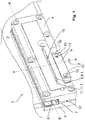
- FIG. 1 shows a door element 3, which is mounted on a corner fitting 1 on a pivot point 2, which may for example also be a BTS axis.
- the corner fitting 1 is clamped in the lower left corner of the door element 3 via abutment sections 6 to the door element 3.
- the Indian FIG. 1 shown corner fitting 1 is designed so that it can be clamped at the upper left or upper right or lower right corner of the door member 3 for supporting the door member 3 on a pivot point 2 and / or an axis.
- the corner fitting 1 consists of a first fitting element 4 and a second fitting element 5. Both Fitting elements 4 and 5 have contact sections 6, which serve at least for indirect installation via an intermediate layer, not shown here, for engagement with the door element 3.
- a clamping area 7, in which the door element 3 is inserted forms.
- a holding element 8 is arranged, which is displaceable relative to the fitting elements 4 and 5, in particular in the longitudinal extent of the fitting elements 4 and 5.
- the connecting element 9 via two fasteners 10 non-positively and / or positively connected to the holding element 8 operatively connected.
- the standing with the connecting element 9 in operative connection holding element 8 is movably guided in a designed as a recess 11.1 in the form of a groove 11 free space in the fitting element 4 and the fitting element.
- the free space 11 is configured in the form of the groove parallel to the longitudinal extent of the fitting elements 4 and 5.
- the retaining element 8 and the connection element 9, which is in operative connection via the fastening elements 10, are parallel along the recess 11.1, ie, displaceable relative to or in the longitudinal extension of the fitting elements 4 and 5.
- the connecting element 9 is displaceable with the retaining element 8 relative to the door member 3 in the opposite direction, the door element 3 can be aligned continuously to the pivot point 2 along the axis BB, for example in its position in a door frame or a glass door system. Is z. B.
- the door element 3 by shifting the Holding element 8 and thus operatively connected to the holding element 8 connecting element 9 on the Pivot and / or the axis can be adjusted.
- the holding element 8 and the connecting element 9 are in the present case designed as two interconnected components which comprise the fastening mechanism, which is presently integrated in both components, namely in the holding element 8 and the connecting element 9.
- the fastening elements 10 which connect the holding element 8 via the connecting part with the connecting element 9, screwed into the bushings 12.
- the holding element 8 performs a lifting movement and clamped at least partially with the head part 8.1 via a support portion 16 at least frictionally in the recess 11.1 designed as a groove 11 in the free space on the fitting elements.
- the displaceability of the retaining element 8 and of the connecting element 9 operatively connected to the retaining element 8 is thus prevented or the retaining element 8 is fixed in its position on the fitting elements 4 and 5.
- a lower recess 18 is configured on the fitting elements 4 and 5, preferably parallel to the as a free space 11 configured recess 11.1 is formed, and preferably extends over the same length as the configured as a free space 11 recess 11.1.
- the lower recess 18 is here is preferably formed in both fitting elements 4 and 5 and extends over the distance 17 of the fitting elements from one to the other fitting element 4 and 5.
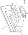
- FIG. 2 shows for better representation of the mounting of the support member 8 in the corner fitting 1, the corner fitting 1 without the front fitting element 4 in the unmounted state.
- the door element 3 outside the abutment section 6 has a cutout in accordance with the known glass cutout standards and lies outside the cutout on the abutment section 6 of the fitting element 5.
- a free space is created in the corner fitting 1, which serves for the arrangement of the holding element 8 and the connecting element 9.
- the fastening mechanism comprises only the retaining element 8 and the connecting element 9, which are connected to one another in a non-positive and / or form-locking manner via two fastening elements 10 that can be operated by the bushings 12 configured on the connecting element 9 (not shown here).
- the advantageously designed as screws or grub screws fasteners 10 are guided or screwed through configured in the connecting element 9 bushings 12 in the form of holes.
- the connecting element 9 and the retaining element 8 comprise the fastening mechanism, which can be transferred to a fixable state for continuously displaceable mounting of the retaining element 8 in a released state, wherein the retaining element 8 is at least frictionally coupled to the fitting element.
- a positioning of the door element 3 indirectly via the orientation of the corner fitting 1 on the axis or the pivot point be determined.
- the operatively connected to the holding element 8 connecting element 9 approximately centrally a receptacle 13, which serves for the arrangement of the door element 3 on the pivot point 2 and / or the axis.
- the receptacle 13 is advantageously adaptable to the pivot point 2 and / or the axis, for example by different adapters. Since the connecting element 9 in the present embodiment is a single component of the corner fitting, this can of course also be connected with different sized receptacles 13 variable with the support member 8 and include the attachment mechanism.
- connection element 9 With the connecting element 9 12 recesses 14 are configured in the connecting element 9 in the region of the bushings, which serve to receive on the holding element 8 configured pin 15, which are formed on the connecting part 8.2 of the holding member 8.
- the pins 15 each have a bore 15.1, through which the fastening elements 10, which are guided in the passages 12 of the connecting element 9, engage.
- the fastening elements 10 serve on the one hand preferably to convert the fastening mechanism, which is formed inter alia of the connecting element 9 and the retaining element 8, in different functional states.
- the connecting element 9 and the retaining element 8 are positively and positively connected via the fastening elements 10 and thereby form a preassembled one-piece component.
- the area formed on the head part 8.1 of the holding element 8 is guided in the fitting element 5 as a recess 11.1 in the form of a groove 11 designed free space.
- have the holes 15.1 in the pin 15 of the support member 8 each means 15.2, in the present case in the form of a chamfer, which leads to a reduction or to an extension of the holes 15.1 serve.
- the function of the means 15.2 is in the FIGS. 4a and 4b shown.
- FIGS. 3a and 3b show in a plan view the underside of the head part 8.1 of the designed as a clamping plate holding member 8 with engagement or support portion 16.
- the engaging portion 16 has a corrugation, for example, as in FIG. 3a shown, a rhombic ribbing on.
- FIG. 3b Another embodiment of the corrugation of the engagement or support portion 16 shows FIG. 3b , wherein a parallel corrugation on the engagement or support portion 16 is configured, which is formed perpendicular to the longitudinal extent of the configured as a recess 11.1 space 11.
- the clamping of designed as a clamping plate holding member 8 can also be done only by adhesion, but limited for a maximum torque which is transmitted via the rotation axis of the bottom-TürSch Strukturer on the support member 8.
- FIGS. 4a and 4b show in a schematic sectional view of the holding element 8, which is designed in T-shape as a T-profile. It shows FIG. 4a the freely movable in dissolved state retaining element 8 and FIG. 4b The frictional connection in the clamping position or in the fixing state with the configured as a recess 11.1 space 11 of the fitting element 4 and 5 holding element 8. The frictional connection between the support member 8 and the recess 11.1 designed as a free space 11 of the fitting element 4 and 5 is effected by propulsion of the fastener 10. As in FIG.
- the fastener 10 in the direction of the bore 15.1 driven, wherein the configured on the fastener 10 conical surface 10.1 presses against the bevel formed in the bore 15.1 means 15.2, whereby the holding member 8 is pulled down, ie in a vertical movement to the movement of the fastener 10 and in the orthogonal direction to the longitudinal extent the fitting elements 4 and 5 performs a lifting movement.
Landscapes
- Engineering & Computer Science (AREA)
- Mechanical Engineering (AREA)
- Hinges (AREA)
- Connection Of Plates (AREA)
- Gasket Seals (AREA)
Claims (10)
- Ferrure d'angle (1) pour un élément de porte (3) agençable sur un point de rotation (2) et/ou un axe, comprenant un premier élément de ferrure (4) et un deuxième élément de ferrure (5), lesquels respectivement comprennent au moins par régions une section de placement (6) pour le placement contre l'élément de porte (3) et sont connectables entre eux tout en serrant l'élément de porte (3),
une région de serrage (7) se formant entre les deux éléments de ferrure (4, 5), dans laquelle l'élément de porte (3) est insérable, et les éléments de ferrure (4, 5) étant aménagés de telle façon qu'un élément de retenue (8) est agencé entre les deux éléments de ferrure (4, 5), lequel est déplaçable par rapport aux éléments de ferrure (4, 5), et l'élément de retenue (8) est en connexion opérationnelle avec l'élément de connexion (9), lequel sert au support de l'élément de porte (3) sur le point de rotation (2) et/ou l'axe, un mécanisme d'attachement étant intégré au moins sur l'élément de retenue (8) de même qu'au moins sur l'élément de connexion (9), lequel mécanisme est transférable entre un état relâché et un état de fixation, dans l'état relâché l'élément de retenue (8) étant déplaçable sur les éléments de ferrure (4, 5), et dans l'état de fixation étant attaché par la force et/ou par la forme sur au moins un des éléments de ferrure (4, 5), l'élément de retenue (8) étant mobile dans un espace libre (11) le long de l'extension longitudinale dudit au moins un élément de ferrure (4, 5), l'espace libre (11) présentant un évidement (11.1) dans ledit au moins un élément de ferrure (4, 5) et l'élément de retenue (8) étant supporte de façon mobile dans l'évidement (11.1), un transfert depuis l'état de fixation vers l'état relâché et vice versa étant exécutable via un élément d'attachement (10) lequel est agencé sur l'élément de connexion (9) de façon accessible depuis l'extérieur pour un utilisateur,
caractérisée en ce
que l'élément de retenue (8) présente au moins un perçage (15.1), dans lequel l'élément d'attachement (10) dans l'état de fixation s'engrène au moins partiellement, ce qui produit un serrage plus fort entre l'élément de retenue (8) et l'évidement (11.1), et dans l'état relâché l'élément d'attachement (10) s'engrène moins avancé dans le perçage (15.1) ou se trouve espacé au perçage (15.1), de sorte que le serrage est plus faible ou le serrage est pratiquement annulé, le perçage (15.1) présentant des moyens (15.2) faisant qu'une pièce de connexion (8.2) de l'élément de retenue (8) lors de l'engrènement de l'élément d'attachement (10) dans le perçage (15.1) bouge verticalement par rapport à la direction de mouvement de l'élément d'attachement (10), l'élément de connexion (9) présentant un passage (12), dans lequel l'élément d'attachement (10) est agencé, le passage (12) s'étendant jusque vers le perçage (15.1), et dans l'état relâché n'étant pas aligné au perçage (15.1). - Ferrure d'angle (1) selon la revendication 1,
caractérisée en ce
que le mécanisme d'attachement est aménagé de telle façon que dans l'état relâché une friction d'adhésion est effective entre l'élément de retenue (8) et l'évidement (11.1), qui est considérablement plus faible que la friction d'adhésion, qui est effective entre l'élément de retenue (8) et l'évidement (11.1) dans l'état de fixation. - Ferrure d'angle (1) selon l'une des revendications précédentes,
caractérisée en ce
que dans l'état de fixation un serrage est effective entre l'élément de retenue (8) et l'évidement (11.1), le serrage empêchant un mouvement de l'élément de retenue (8) par rapport à l'élément de ferrure (4, 5). - Ferrure d'angle (1) selon l'une des revendications précédentes,
caractérisée en ce
que le mécanisme d'attachement est aménagé de telle façon que lors du transfert depuis l'état de fixation vers l'état relâché et vice versa l'élément de retenue (8) effectue un mouvement de levage à l'intérieur de l'espace libre (11). - Ferrure d'angle (1) selon l'une des revendications précédentes,
caractérisée en ce
que le perçage (15.1) et/ou le passage (12) présentent un taraudage, dans lequel l'élément d'attachement (10) arrive à l'engrènement par la force et/ou par la forme. - Ferrure d'angle (1) selon l'une des revendications précédentes,
caractérisée en ce
que l'évidement (11.1) s'étend le long de l'extension longitudinale de l'élément de ferrure (4, 5), et l'élément de retenue (8) est supporté de façon mobile avec une partie de tête (8.1) dans l'évidement (11.1), dans l'état de fixation l'élément de retenue (8) avec une section d'appui, respectivement d'engrènement (16) qui se trouve tout particulièrement sur la partie de tête (8.1) restant contre l'évidement (11.1). - Ferrure d'angle (1) selon l'une des revendications précédentes,
caractérisée en ce
que la surface de la section d'appui, respectivement d'engrènement (16) et/ou de l'évidement (11/1), qui agit sur la section d'appui, respectivement d'engrènement (16) en l'état de fixation, présente une rugosité et/ou cannelage élevé. - Ferrure d'angle (1) selon l'une des revendications précédentes,
caractérisée en ce
que l'élément de retenue (8) présente une pièce de connexion (8.2), sur laquelle l'élément de connexion (9) est attaché par l'intermédiaire de l'élément d'attachement (10), tout particulièrement la partie de tête (8.1) et la pièce de connexion (8.2) étant alignées verticalement l'une par rapport à l'autre et/ou formant un composant monolithique et/ou intégral. - Ferrure d'angle (1) selon l'une des revendications précédentes,
caractérisée en ce
que l'élément de retenue (8) est déplaçable le long de l'extension longitudinale de l'élément de ferrure (4, 5) par l'intermédiaire de la pièce de connexion (8.2) dans un espace libre (17) en une première direction de mouvement, l'espace libre (17) étant aménagé de telle façon par rapport à l'élément de retenue (8) que l'élément de retenue (8) est déplaçable orthogonalement par rapport à la première direction de mouvement vers une deuxième direction de mouvement. - Méthode pour l'agencement d'un élément de porte (3) sur un point de rotation (2) et/ou un axe par l'intermédiaire d'une ferrure d'angle (1) selon l'une des revendications 1 à 9, comprenant un premier élément de ferrure (4) et un deuxième élément de ferrure (5), lesquels comprennent respectivement au moins par régions une section de placement (6) pour le placement contre l'élément de porte (3) et sont connectables entre eux tout en serrant l'élément de porte (3),
caractérisée en ce
que la ferrure d'angle (1) présente un mécanisme d'attachement, lequel est transférable entre un état relâché et un état de fixation, en l'état relâché un élément de connexion (9) supporté de façon déplaçable dans la ferrure d'angle (1) étant aligné sur le point de rotation (2) et/ou l'axe, et suivant l'alignement de l'élément de connexion (9) sur le point de rotation (2) et/ou l'axe, le mécanisme d'attachement étant transféré vers l'état de fixation de sorte que l'élément de retenue (8) est attaché de façon serrée sur au moins un élément de ferrure (4, 5) ce qui exclut un mouvement relatif entre l'élément de retenue (8) et l'élément de ferrure (4, 5).
Priority Applications (5)
| Application Number | Priority Date | Filing Date | Title |
|---|---|---|---|
| ES14196234T ES2717935T3 (es) | 2014-12-04 | 2014-12-04 | Herraje de esquina ajustable con elemento de retención |
| EP14196234.0A EP3029236B1 (fr) | 2014-12-04 | 2014-12-04 | Ferrure d'angle réglable dotée d'un élément de retenue |
| CN201510325157.6A CN106193941B (zh) | 2014-12-04 | 2015-06-12 | 具有保持元件的能调节的包角 |
| AU2015264825A AU2015264825B2 (en) | 2014-12-04 | 2015-12-02 | Adjustable corner fitting with holding element |
| US14/958,721 US9605458B2 (en) | 2014-12-04 | 2015-12-03 | Adjustable corner fitting with holding element |
Applications Claiming Priority (1)
| Application Number | Priority Date | Filing Date | Title |
|---|---|---|---|
| EP14196234.0A EP3029236B1 (fr) | 2014-12-04 | 2014-12-04 | Ferrure d'angle réglable dotée d'un élément de retenue |
Publications (2)
| Publication Number | Publication Date |
|---|---|
| EP3029236A1 EP3029236A1 (fr) | 2016-06-08 |
| EP3029236B1 true EP3029236B1 (fr) | 2019-02-20 |
Family
ID=52011049
Family Applications (1)
| Application Number | Title | Priority Date | Filing Date |
|---|---|---|---|
| EP14196234.0A Not-in-force EP3029236B1 (fr) | 2014-12-04 | 2014-12-04 | Ferrure d'angle réglable dotée d'un élément de retenue |
Country Status (5)
| Country | Link |
|---|---|
| US (1) | US9605458B2 (fr) |
| EP (1) | EP3029236B1 (fr) |
| CN (1) | CN106193941B (fr) |
| AU (1) | AU2015264825B2 (fr) |
| ES (1) | ES2717935T3 (fr) |
Families Citing this family (2)
| Publication number | Priority date | Publication date | Assignee | Title |
|---|---|---|---|---|
| EP3029241A1 (fr) * | 2014-12-04 | 2016-06-08 | DORMA Deutschland GmbH | Ferrure d'angle à force de serrage accrue |
| IT202100024731A1 (it) * | 2021-09-28 | 2023-03-28 | Pdp Box Doccia S P A | Cerniera e anta battente comprendente tale cerniera |
Family Cites Families (20)
| Publication number | Priority date | Publication date | Assignee | Title |
|---|---|---|---|---|
| US3828394A (en) * | 1971-01-18 | 1974-08-13 | Blumcraft Pittsburgh | Hinge-device and method |
| JPS5628297Y2 (fr) * | 1976-08-13 | 1981-07-06 | ||
| US4200956A (en) * | 1977-06-15 | 1980-05-06 | M.M.G., Inc. | Hinge, handle and detent |
| NL7807767A (nl) * | 1977-08-05 | 1979-02-07 | Yoshida Kogyo Kk | Draaimechanisme voor draairamen. |
| DE3008223A1 (de) * | 1980-03-04 | 1981-09-10 | Vereinigte Glaswerke Gmbh, 5100 Aachen | Drehbeschlag fuer ganzglastueren |
| US4513474A (en) * | 1982-08-27 | 1985-04-30 | Santo Industries Co., Ltd. | Wedge hinge having an axially movable pivot |
| DE3538064A1 (de) * | 1985-10-25 | 1987-04-30 | Marinoni & Figli Casma | Beschlag fuer einen ganzglasfluegel, insbesondere fuer ganzglastueren, ganzglasfenster, ganzglasoberlichter und ganzglasvitrinenscheiben |
| DE8536840U1 (de) * | 1985-10-25 | 1990-02-08 | Società Italiana Progetti S.r.l., Magenta, Mailand/Milano | Beschlag für einen Ganzglasflügel, insbesondere für Ganzglastüren, Ganzglasfenster, Ganzglasoberlichter und Ganzglasvitrinenscheiben |
| DE3806199A1 (de) * | 1988-02-26 | 1989-09-07 | Casma Spa | Ganzglastuer mit ortsfestem schwenkzapfen |
| DE4107327A1 (de) * | 1991-03-07 | 1992-09-10 | Italiana Progetti | Ganzglastuer |
| DE9318246U1 (de) * | 1993-11-29 | 1994-10-27 | Società Italiana Progetti S.r.l., Magenta, Mailand/Milano | Tür- oder Fensterbeschlag |
| US5613276A (en) * | 1995-12-20 | 1997-03-25 | Franz; George W. | Glass shower door hinge system and method |
| CA2240758C (fr) * | 1995-12-22 | 2001-07-24 | Societa Italiana Progetti S.R.L. | Dispositif de montage pour battant de porte |
| US6643898B1 (en) * | 2002-05-18 | 2003-11-11 | Southeastern Aluminum Products, Inc. | Self-centering pivot door hinge system |
| US7493673B2 (en) * | 2005-04-21 | 2009-02-24 | Custom Hardware Mfg. Inc. | Notchless glass plate clamp |
| US7607199B2 (en) * | 2005-06-13 | 2009-10-27 | C.R. Laurence Company, Inc. | Frameless glass door hinge |
| DE102009022803B4 (de) * | 2009-05-27 | 2017-08-03 | Dormakaba Deutschland Gmbh | Dreiteiliger Universaltürbeschlag |
| TW201331461A (zh) * | 2012-01-19 | 2013-08-01 | Leado Door Controls Ltd | 用於玻璃門之自動歸位機構 |
| TW201402928A (zh) * | 2012-07-06 | 2014-01-16 | Leado Door Controls Ltd | 用於玻璃門之自動歸位裝置 |
| US8528169B1 (en) * | 2012-09-11 | 2013-09-10 | Leado Door Controls Ltd. | Patch fitting with auto-return function |
-
2014
- 2014-12-04 ES ES14196234T patent/ES2717935T3/es active Active
- 2014-12-04 EP EP14196234.0A patent/EP3029236B1/fr not_active Not-in-force
-
2015
- 2015-06-12 CN CN201510325157.6A patent/CN106193941B/zh not_active Expired - Fee Related
- 2015-12-02 AU AU2015264825A patent/AU2015264825B2/en not_active Ceased
- 2015-12-03 US US14/958,721 patent/US9605458B2/en active Active
Non-Patent Citations (1)
| Title |
|---|
| None * |
Also Published As
| Publication number | Publication date |
|---|---|
| US9605458B2 (en) | 2017-03-28 |
| AU2015264825B2 (en) | 2020-08-20 |
| CN106193941A (zh) | 2016-12-07 |
| ES2717935T3 (es) | 2019-06-26 |
| EP3029236A1 (fr) | 2016-06-08 |
| US20160160548A1 (en) | 2016-06-09 |
| CN106193941B (zh) | 2021-01-15 |
| AU2015264825A1 (en) | 2016-06-23 |
Similar Documents
| Publication | Publication Date | Title |
|---|---|---|
| EP2715021B1 (fr) | Scharnière | |
| DE4219681C2 (de) | Einstellbares Abhebescharnier | |
| EP3029238B1 (fr) | Ferrure d'angle dotée d'une plage de serrage réglable | |
| DE2614446A1 (de) | Scharnier | |
| EP3103948B1 (fr) | Penture pour une porte ou une fenêtre | |
| EP2159345B1 (fr) | Fixation pour éléments de revêtement | |
| EP2927409B1 (fr) | Joint pour une porte coulissante | |
| EP2345787B1 (fr) | Penture de porte pour portes en aluminium | |
| EP3029236B1 (fr) | Ferrure d'angle réglable dotée d'un élément de retenue | |
| EP3029235B1 (fr) | Ferrure d'angle destinée à l'agencement d'un élément de porte sur un pivot ou un axe | |
| EP2345786A2 (fr) | Penture de porte pour portes en aluminium | |
| EP3029237B1 (fr) | Ferrure d'angle | |
| EP3029240A1 (fr) | Ferrure d'angle dotée d'une plage de réglage variable | |
| EP3029234B1 (fr) | Ferrure d'angle réglable | |
| DE3920141C1 (fr) | ||
| EP2169167A1 (fr) | Dispositif de réglage de la distance entre deux chariots se déplaçant sur un rail commun et procédé | |
| EP3029227B1 (fr) | Ferrure dotée d'une plage de serrage réglable | |
| EP2108774B1 (fr) | Charnière | |
| DE102013200305B4 (de) | Trennwand | |
| EP2740872B1 (fr) | Palier d'angle prévu pour l'agencement recouvert | |
| EP0445363A1 (fr) | Dispositif de fraisage ou perçage | |
| DE3243805C2 (fr) | ||
| EP3029241A1 (fr) | Ferrure d'angle à force de serrage accrue | |
| DE102006012051B4 (de) | Bandaufnahme mit integrierter Höhenverstellung für Türzargen zur Aufnahme von Rahmenteilen zur dreidimensionalen Verstellung | |
| CH632802A5 (de) | Vorrichtung zum befestigen eines tuerschliessers. |
Legal Events
| Date | Code | Title | Description |
|---|---|---|---|
| PUAI | Public reference made under article 153(3) epc to a published international application that has entered the european phase |
Free format text: ORIGINAL CODE: 0009012 |
|
| AK | Designated contracting states |
Kind code of ref document: A1 Designated state(s): AL AT BE BG CH CY CZ DE DK EE ES FI FR GB GR HR HU IE IS IT LI LT LU LV MC MK MT NL NO PL PT RO RS SE SI SK SM TR |
|
| AX | Request for extension of the european patent |
Extension state: BA ME |
|
| STAA | Information on the status of an ep patent application or granted ep patent |
Free format text: STATUS: REQUEST FOR EXAMINATION WAS MADE |
|
| 17P | Request for examination filed |
Effective date: 20161121 |
|
| RBV | Designated contracting states (corrected) |
Designated state(s): AL AT BE BG CH CY CZ DE DK EE ES FI FR GB GR HR HU IE IS IT LI LT LU LV MC MK MT NL NO PL PT RO RS SE SI SK SM TR |
|
| RAP1 | Party data changed (applicant data changed or rights of an application transferred) |
Owner name: DORMAKABA DEUTSCHLAND GMBH |
|
| STAA | Information on the status of an ep patent application or granted ep patent |
Free format text: STATUS: EXAMINATION IS IN PROGRESS |
|
| 17Q | First examination report despatched |
Effective date: 20180411 |
|
| RIC1 | Information provided on ipc code assigned before grant |
Ipc: E05D 7/081 20060101ALI20180621BHEP Ipc: E05D 15/54 20060101ALN20180621BHEP Ipc: E05D 7/04 20060101ALI20180621BHEP Ipc: E05D 5/02 20060101AFI20180621BHEP |
|
| GRAP | Despatch of communication of intention to grant a patent |
Free format text: ORIGINAL CODE: EPIDOSNIGR1 |
|
| STAA | Information on the status of an ep patent application or granted ep patent |
Free format text: STATUS: GRANT OF PATENT IS INTENDED |
|
| INTG | Intention to grant announced |
Effective date: 20180905 |
|
| GRAS | Grant fee paid |
Free format text: ORIGINAL CODE: EPIDOSNIGR3 |
|
| GRAA | (expected) grant |
Free format text: ORIGINAL CODE: 0009210 |
|
| STAA | Information on the status of an ep patent application or granted ep patent |
Free format text: STATUS: THE PATENT HAS BEEN GRANTED |
|
| AK | Designated contracting states |
Kind code of ref document: B1 Designated state(s): AL AT BE BG CH CY CZ DE DK EE ES FI FR GB GR HR HU IE IS IT LI LT LU LV MC MK MT NL NO PL PT RO RS SE SI SK SM TR |
|
| REG | Reference to a national code |
Ref country code: GB Ref legal event code: FG4D Free format text: NOT ENGLISH |
|
| REG | Reference to a national code |
Ref country code: CH Ref legal event code: EP |
|
| REG | Reference to a national code |
Ref country code: DE Ref legal event code: R096 Ref document number: 502014010843 Country of ref document: DE |
|
| REG | Reference to a national code |
Ref country code: AT Ref legal event code: REF Ref document number: 1098391 Country of ref document: AT Kind code of ref document: T Effective date: 20190315 |
|
| REG | Reference to a national code |
Ref country code: IE Ref legal event code: FG4D Free format text: LANGUAGE OF EP DOCUMENT: GERMAN |
|
| REG | Reference to a national code |
Ref country code: CH Ref legal event code: NV Representative=s name: RENTSCH PARTNER AG, CH |
|
| REG | Reference to a national code |
Ref country code: ES Ref legal event code: FG2A Ref document number: 2717935 Country of ref document: ES Kind code of ref document: T3 Effective date: 20190626 Ref country code: NL Ref legal event code: MP Effective date: 20190220 |
|
| REG | Reference to a national code |
Ref country code: LT Ref legal event code: MG4D |
|
| PG25 | Lapsed in a contracting state [announced via postgrant information from national office to epo] |
Ref country code: NO Free format text: LAPSE BECAUSE OF FAILURE TO SUBMIT A TRANSLATION OF THE DESCRIPTION OR TO PAY THE FEE WITHIN THE PRESCRIBED TIME-LIMIT Effective date: 20190520 Ref country code: FI Free format text: LAPSE BECAUSE OF FAILURE TO SUBMIT A TRANSLATION OF THE DESCRIPTION OR TO PAY THE FEE WITHIN THE PRESCRIBED TIME-LIMIT Effective date: 20190220 Ref country code: PT Free format text: LAPSE BECAUSE OF FAILURE TO SUBMIT A TRANSLATION OF THE DESCRIPTION OR TO PAY THE FEE WITHIN THE PRESCRIBED TIME-LIMIT Effective date: 20190620 Ref country code: SE Free format text: LAPSE BECAUSE OF FAILURE TO SUBMIT A TRANSLATION OF THE DESCRIPTION OR TO PAY THE FEE WITHIN THE PRESCRIBED TIME-LIMIT Effective date: 20190220 Ref country code: NL Free format text: LAPSE BECAUSE OF FAILURE TO SUBMIT A TRANSLATION OF THE DESCRIPTION OR TO PAY THE FEE WITHIN THE PRESCRIBED TIME-LIMIT Effective date: 20190220 Ref country code: LT Free format text: LAPSE BECAUSE OF FAILURE TO SUBMIT A TRANSLATION OF THE DESCRIPTION OR TO PAY THE FEE WITHIN THE PRESCRIBED TIME-LIMIT Effective date: 20190220 |
|
| PG25 | Lapsed in a contracting state [announced via postgrant information from national office to epo] |
Ref country code: LV Free format text: LAPSE BECAUSE OF FAILURE TO SUBMIT A TRANSLATION OF THE DESCRIPTION OR TO PAY THE FEE WITHIN THE PRESCRIBED TIME-LIMIT Effective date: 20190220 Ref country code: GR Free format text: LAPSE BECAUSE OF FAILURE TO SUBMIT A TRANSLATION OF THE DESCRIPTION OR TO PAY THE FEE WITHIN THE PRESCRIBED TIME-LIMIT Effective date: 20190521 Ref country code: HR Free format text: LAPSE BECAUSE OF FAILURE TO SUBMIT A TRANSLATION OF THE DESCRIPTION OR TO PAY THE FEE WITHIN THE PRESCRIBED TIME-LIMIT Effective date: 20190220 Ref country code: BG Free format text: LAPSE BECAUSE OF FAILURE TO SUBMIT A TRANSLATION OF THE DESCRIPTION OR TO PAY THE FEE WITHIN THE PRESCRIBED TIME-LIMIT Effective date: 20190520 Ref country code: IS Free format text: LAPSE BECAUSE OF FAILURE TO SUBMIT A TRANSLATION OF THE DESCRIPTION OR TO PAY THE FEE WITHIN THE PRESCRIBED TIME-LIMIT Effective date: 20190620 Ref country code: RS Free format text: LAPSE BECAUSE OF FAILURE TO SUBMIT A TRANSLATION OF THE DESCRIPTION OR TO PAY THE FEE WITHIN THE PRESCRIBED TIME-LIMIT Effective date: 20190220 |
|
| PG25 | Lapsed in a contracting state [announced via postgrant information from national office to epo] |
Ref country code: DK Free format text: LAPSE BECAUSE OF FAILURE TO SUBMIT A TRANSLATION OF THE DESCRIPTION OR TO PAY THE FEE WITHIN THE PRESCRIBED TIME-LIMIT Effective date: 20190220 Ref country code: EE Free format text: LAPSE BECAUSE OF FAILURE TO SUBMIT A TRANSLATION OF THE DESCRIPTION OR TO PAY THE FEE WITHIN THE PRESCRIBED TIME-LIMIT Effective date: 20190220 Ref country code: CZ Free format text: LAPSE BECAUSE OF FAILURE TO SUBMIT A TRANSLATION OF THE DESCRIPTION OR TO PAY THE FEE WITHIN THE PRESCRIBED TIME-LIMIT Effective date: 20190220 Ref country code: RO Free format text: LAPSE BECAUSE OF FAILURE TO SUBMIT A TRANSLATION OF THE DESCRIPTION OR TO PAY THE FEE WITHIN THE PRESCRIBED TIME-LIMIT Effective date: 20190220 Ref country code: SK Free format text: LAPSE BECAUSE OF FAILURE TO SUBMIT A TRANSLATION OF THE DESCRIPTION OR TO PAY THE FEE WITHIN THE PRESCRIBED TIME-LIMIT Effective date: 20190220 Ref country code: AL Free format text: LAPSE BECAUSE OF FAILURE TO SUBMIT A TRANSLATION OF THE DESCRIPTION OR TO PAY THE FEE WITHIN THE PRESCRIBED TIME-LIMIT Effective date: 20190220 |
|
| REG | Reference to a national code |
Ref country code: DE Ref legal event code: R097 Ref document number: 502014010843 Country of ref document: DE |
|
| PG25 | Lapsed in a contracting state [announced via postgrant information from national office to epo] |
Ref country code: PL Free format text: LAPSE BECAUSE OF FAILURE TO SUBMIT A TRANSLATION OF THE DESCRIPTION OR TO PAY THE FEE WITHIN THE PRESCRIBED TIME-LIMIT Effective date: 20190220 Ref country code: SM Free format text: LAPSE BECAUSE OF FAILURE TO SUBMIT A TRANSLATION OF THE DESCRIPTION OR TO PAY THE FEE WITHIN THE PRESCRIBED TIME-LIMIT Effective date: 20190220 |
|
| PLBE | No opposition filed within time limit |
Free format text: ORIGINAL CODE: 0009261 |
|
| STAA | Information on the status of an ep patent application or granted ep patent |
Free format text: STATUS: NO OPPOSITION FILED WITHIN TIME LIMIT |
|
| 26N | No opposition filed |
Effective date: 20191121 |
|
| PG25 | Lapsed in a contracting state [announced via postgrant information from national office to epo] |
Ref country code: SI Free format text: LAPSE BECAUSE OF FAILURE TO SUBMIT A TRANSLATION OF THE DESCRIPTION OR TO PAY THE FEE WITHIN THE PRESCRIBED TIME-LIMIT Effective date: 20190220 |
|
| PG25 | Lapsed in a contracting state [announced via postgrant information from national office to epo] |
Ref country code: TR Free format text: LAPSE BECAUSE OF FAILURE TO SUBMIT A TRANSLATION OF THE DESCRIPTION OR TO PAY THE FEE WITHIN THE PRESCRIBED TIME-LIMIT Effective date: 20190220 |
|
| REG | Reference to a national code |
Ref country code: BE Ref legal event code: MM Effective date: 20191231 |
|
| PG25 | Lapsed in a contracting state [announced via postgrant information from national office to epo] |
Ref country code: MC Free format text: LAPSE BECAUSE OF FAILURE TO SUBMIT A TRANSLATION OF THE DESCRIPTION OR TO PAY THE FEE WITHIN THE PRESCRIBED TIME-LIMIT Effective date: 20190220 |
|
| GBPC | Gb: european patent ceased through non-payment of renewal fee |
Effective date: 20191204 |
|
| PG25 | Lapsed in a contracting state [announced via postgrant information from national office to epo] |
Ref country code: IE Free format text: LAPSE BECAUSE OF NON-PAYMENT OF DUE FEES Effective date: 20191204 Ref country code: GB Free format text: LAPSE BECAUSE OF NON-PAYMENT OF DUE FEES Effective date: 20191204 Ref country code: LU Free format text: LAPSE BECAUSE OF NON-PAYMENT OF DUE FEES Effective date: 20191204 |
|
| PG25 | Lapsed in a contracting state [announced via postgrant information from national office to epo] |
Ref country code: BE Free format text: LAPSE BECAUSE OF NON-PAYMENT OF DUE FEES Effective date: 20191231 |
|
| PG25 | Lapsed in a contracting state [announced via postgrant information from national office to epo] |
Ref country code: CY Free format text: LAPSE BECAUSE OF FAILURE TO SUBMIT A TRANSLATION OF THE DESCRIPTION OR TO PAY THE FEE WITHIN THE PRESCRIBED TIME-LIMIT Effective date: 20190220 |
|
| PG25 | Lapsed in a contracting state [announced via postgrant information from national office to epo] |
Ref country code: HU Free format text: LAPSE BECAUSE OF FAILURE TO SUBMIT A TRANSLATION OF THE DESCRIPTION OR TO PAY THE FEE WITHIN THE PRESCRIBED TIME-LIMIT; INVALID AB INITIO Effective date: 20141204 Ref country code: MT Free format text: LAPSE BECAUSE OF FAILURE TO SUBMIT A TRANSLATION OF THE DESCRIPTION OR TO PAY THE FEE WITHIN THE PRESCRIBED TIME-LIMIT Effective date: 20190220 |
|
| REG | Reference to a national code |
Ref country code: DE Ref legal event code: R081 Ref document number: 502014010843 Country of ref document: DE Owner name: DORMA-GLAS GMBH, DE Free format text: FORMER OWNER: DORMAKABA DEUTSCHLAND GMBH, 58256 ENNEPETAL, DE |
|
| PGFP | Annual fee paid to national office [announced via postgrant information from national office to epo] |
Ref country code: FR Payment date: 20211224 Year of fee payment: 8 Ref country code: DE Payment date: 20211210 Year of fee payment: 8 Ref country code: AT Payment date: 20211222 Year of fee payment: 8 |
|
| PGFP | Annual fee paid to national office [announced via postgrant information from national office to epo] |
Ref country code: CH Payment date: 20211221 Year of fee payment: 8 |
|
| REG | Reference to a national code |
Ref country code: ES Ref legal event code: PC2A Owner name: DORMA-GLAS GMBH Effective date: 20220303 |
|
| REG | Reference to a national code |
Ref country code: AT Ref legal event code: PC Ref document number: 1098391 Country of ref document: AT Kind code of ref document: T Owner name: DORMA-GLAS GMBH, DE Effective date: 20220216 |
|
| PGFP | Annual fee paid to national office [announced via postgrant information from national office to epo] |
Ref country code: IT Payment date: 20211224 Year of fee payment: 8 Ref country code: ES Payment date: 20220222 Year of fee payment: 8 |
|
| PG25 | Lapsed in a contracting state [announced via postgrant information from national office to epo] |
Ref country code: MK Free format text: LAPSE BECAUSE OF FAILURE TO SUBMIT A TRANSLATION OF THE DESCRIPTION OR TO PAY THE FEE WITHIN THE PRESCRIBED TIME-LIMIT Effective date: 20190220 |
|
| REG | Reference to a national code |
Ref country code: DE Ref legal event code: R119 Ref document number: 502014010843 Country of ref document: DE |
|
| REG | Reference to a national code |
Ref country code: CH Ref legal event code: PL |
|
| REG | Reference to a national code |
Ref country code: AT Ref legal event code: MM01 Ref document number: 1098391 Country of ref document: AT Kind code of ref document: T Effective date: 20221204 |
|
| PG25 | Lapsed in a contracting state [announced via postgrant information from national office to epo] |
Ref country code: LI Free format text: LAPSE BECAUSE OF NON-PAYMENT OF DUE FEES Effective date: 20221231 Ref country code: DE Free format text: LAPSE BECAUSE OF NON-PAYMENT OF DUE FEES Effective date: 20230701 Ref country code: CH Free format text: LAPSE BECAUSE OF NON-PAYMENT OF DUE FEES Effective date: 20221231 Ref country code: AT Free format text: LAPSE BECAUSE OF NON-PAYMENT OF DUE FEES Effective date: 20221204 |
|
| PG25 | Lapsed in a contracting state [announced via postgrant information from national office to epo] |
Ref country code: FR Free format text: LAPSE BECAUSE OF NON-PAYMENT OF DUE FEES Effective date: 20221231 |
|
| REG | Reference to a national code |
Ref country code: ES Ref legal event code: FD2A Effective date: 20240126 |
|
| PG25 | Lapsed in a contracting state [announced via postgrant information from national office to epo] |
Ref country code: IT Free format text: LAPSE BECAUSE OF NON-PAYMENT OF DUE FEES Effective date: 20221204 |
|
| PG25 | Lapsed in a contracting state [announced via postgrant information from national office to epo] |
Ref country code: ES Free format text: LAPSE BECAUSE OF NON-PAYMENT OF DUE FEES Effective date: 20221205 |
|
| PG25 | Lapsed in a contracting state [announced via postgrant information from national office to epo] |
Ref country code: ES Free format text: LAPSE BECAUSE OF NON-PAYMENT OF DUE FEES Effective date: 20221205 |