EP3029247B1 - Schiebetür oder fensteranordnung mit niedriger bodenschwellenhöhe - Google Patents
Schiebetür oder fensteranordnung mit niedriger bodenschwellenhöhe Download PDFInfo
- Publication number
- EP3029247B1 EP3029247B1 EP15198315.2A EP15198315A EP3029247B1 EP 3029247 B1 EP3029247 B1 EP 3029247B1 EP 15198315 A EP15198315 A EP 15198315A EP 3029247 B1 EP3029247 B1 EP 3029247B1
- Authority
- EP
- European Patent Office
- Prior art keywords
- sliding panel
- sealing
- wagon
- sealing plate
- sliding
- Prior art date
- Legal status (The legal status is an assumption and is not a legal conclusion. Google has not performed a legal analysis and makes no representation as to the accuracy of the status listed.)
- Active
Links
Images


Classifications
-
- E—FIXED CONSTRUCTIONS
- E05—LOCKS; KEYS; WINDOW OR DOOR FITTINGS; SAFES
- E05D—HINGES OR SUSPENSION DEVICES FOR DOORS, WINDOWS OR WINGS
- E05D15/00—Suspension arrangements for wings
- E05D15/06—Suspension arrangements for wings for wings sliding horizontally more or less in their own plane
- E05D15/10—Suspension arrangements for wings for wings sliding horizontally more or less in their own plane movable out of one plane into a second parallel plane
- E05D15/1005—Suspension arrangements for wings for wings sliding horizontally more or less in their own plane movable out of one plane into a second parallel plane the wing being supported on arms movable in horizontal planes
- E05D15/1013—Suspension arrangements for wings for wings sliding horizontally more or less in their own plane movable out of one plane into a second parallel plane the wing being supported on arms movable in horizontal planes specially adapted for windows
-
- E—FIXED CONSTRUCTIONS
- E05—LOCKS; KEYS; WINDOW OR DOOR FITTINGS; SAFES
- E05D—HINGES OR SUSPENSION DEVICES FOR DOORS, WINDOWS OR WINGS
- E05D15/00—Suspension arrangements for wings
- E05D15/06—Suspension arrangements for wings for wings sliding horizontally more or less in their own plane
- E05D15/10—Suspension arrangements for wings for wings sliding horizontally more or less in their own plane movable out of one plane into a second parallel plane
- E05D15/1005—Suspension arrangements for wings for wings sliding horizontally more or less in their own plane movable out of one plane into a second parallel plane the wing being supported on arms movable in horizontal planes
-
- E—FIXED CONSTRUCTIONS
- E06—DOORS, WINDOWS, SHUTTERS, OR ROLLER BLINDS IN GENERAL; LADDERS
- E06B—FIXED OR MOVABLE CLOSURES FOR OPENINGS IN BUILDINGS, VEHICLES, FENCES OR LIKE ENCLOSURES IN GENERAL, e.g. DOORS, WINDOWS, BLINDS, GATES
- E06B7/00—Special arrangements or measures in connection with doors or windows
- E06B7/16—Sealing arrangements on wings or parts co-operating with the wings
- E06B7/22—Sealing arrangements on wings or parts co-operating with the wings by means of elastic edgings, e.g. elastic rubber tubes; by means of resilient edgings, e.g. felt or plush strips, resilient metal strips
-
- E—FIXED CONSTRUCTIONS
- E05—LOCKS; KEYS; WINDOW OR DOOR FITTINGS; SAFES
- E05D—HINGES OR SUSPENSION DEVICES FOR DOORS, WINDOWS OR WINGS
- E05D15/00—Suspension arrangements for wings
- E05D15/06—Suspension arrangements for wings for wings sliding horizontally more or less in their own plane
- E05D15/10—Suspension arrangements for wings for wings sliding horizontally more or less in their own plane movable out of one plane into a second parallel plane
- E05D2015/1028—Suspension arrangements for wings for wings sliding horizontally more or less in their own plane movable out of one plane into a second parallel plane with only the wing moving transversely
- E05D2015/1031—Suspension arrangements for wings for wings sliding horizontally more or less in their own plane movable out of one plane into a second parallel plane with only the wing moving transversely the wing supported on arms extending from the carriage
-
- E—FIXED CONSTRUCTIONS
- E05—LOCKS; KEYS; WINDOW OR DOOR FITTINGS; SAFES
- E05Y—INDEXING SCHEME ASSOCIATED WITH SUBCLASSES E05D AND E05F, RELATING TO CONSTRUCTION ELEMENTS, ELECTRIC CONTROL, POWER SUPPLY, POWER SIGNAL OR TRANSMISSION, USER INTERFACES, MOUNTING OR COUPLING, DETAILS, ACCESSORIES, AUXILIARY OPERATIONS NOT OTHERWISE PROVIDED FOR, APPLICATION THEREOF
- E05Y2201/00—Constructional elements; Accessories therefor
- E05Y2201/10—Covers; Housings
- E05Y2201/11—Covers
-
- E—FIXED CONSTRUCTIONS
- E05—LOCKS; KEYS; WINDOW OR DOOR FITTINGS; SAFES
- E05Y—INDEXING SCHEME ASSOCIATED WITH SUBCLASSES E05D AND E05F, RELATING TO CONSTRUCTION ELEMENTS, ELECTRIC CONTROL, POWER SUPPLY, POWER SIGNAL OR TRANSMISSION, USER INTERFACES, MOUNTING OR COUPLING, DETAILS, ACCESSORIES, AUXILIARY OPERATIONS NOT OTHERWISE PROVIDED FOR, APPLICATION THEREOF
- E05Y2201/00—Constructional elements; Accessories therefor
- E05Y2201/60—Suspension or transmission members; Accessories therefor
- E05Y2201/622—Suspension or transmission members elements
- E05Y2201/64—Carriers
-
- E—FIXED CONSTRUCTIONS
- E05—LOCKS; KEYS; WINDOW OR DOOR FITTINGS; SAFES
- E05Y—INDEXING SCHEME ASSOCIATED WITH SUBCLASSES E05D AND E05F, RELATING TO CONSTRUCTION ELEMENTS, ELECTRIC CONTROL, POWER SUPPLY, POWER SIGNAL OR TRANSMISSION, USER INTERFACES, MOUNTING OR COUPLING, DETAILS, ACCESSORIES, AUXILIARY OPERATIONS NOT OTHERWISE PROVIDED FOR, APPLICATION THEREOF
- E05Y2800/00—Details, accessories and auxiliary operations not otherwise provided for
- E05Y2800/10—Additional functions
- E05Y2800/12—Sealing
Definitions
- the current invention relates to an inwardly or outwardly opening sliding door or window assembly with a low bottom sill height.
- the current invention relates to a sliding door or window assembly
- a sliding door or window assembly comprising: a frame having a bottom sill, said bottom sill having a sealing surface, a sliding panel moveable between an open position and a closed position, said sliding panel having a bottom sealing surface which is sealed against the sealing surface of the bottom sill of the frame in the closed position of the sliding panel to provide a sealing interface between the bottom sill and the sliding panel, a track, a wagon arranged to be displaceable along the track, and a displacement mechanism connecting the sliding panel and the wagon, said displacement mechanism arranged such that the sliding panel is displaceable with respect to the wagon in a direction having a vector component which is perpendicular to the plane of the sliding panel.
- the term “sealing interface” should be understood as the interface or connection between two individual and with respect to each other displaceable elements which creates a weatherproof seal between the two elements.
- the term “sealing surface” should be understood as a surface of an element which forms one part of a “sealing interface”. In other words, when two elements come into contact with each other to form a sealing interface, the surfaces on the parts which are in contact with each other will be termed “sealing surfaces”.
- inner and outer refer to the two sides of a wall in which the door or window assembly is mounted.
- the door/window assembly will be mounted in an exterior wall where the term inner side refers to the interior side of the wall and the term outer side refers to the exterior side of the wall.
- inner and outer can be interpreted as the first and second major surface of the assembly. An object which is on the inner side of the assembly will be located closer to the inner side of the wall and an object which is on the outer side of the assembly will be located closer to the outer side of the wall.
- Sliding doors/windows are typically comprised of two panels, a fixed panel which is fixed in position and a sliding panel which slides relative to the fixed panel. This is typical for assemblies which comprise glass panes as the panels.
- sliding door or window assemblies are provided without a "fixed panel" as such.
- the assembly comprises a sliding panel which is placed adjacent a fixed wall section.
- the sliding panel could be arranged to slide past a fixed post element instead of a fixed panel element.
- the sliding panel is connected to a wagon which slides on a track.
- the track will be arranged parallel with the plane of the sliding panel in the closed position of the door.
- the track will be arranged underneath the fixed panel such that the track is hidden underneath the fixed panel.
- the sliding panel will be connected to two wagons, one arranged at each side of the sliding panel.
- the displacement mechanism used to displace the sliding panel perpendicularly to the plane of the sliding panel is typically a pivotable arm assembly where one end of the arm is pivotably connected to the wagon and the other end of the arm is pivotably connected to the sliding panel.
- Sliding doors can furthermore be classified into one of two main kinds.
- a first kind of sliding door when the door is in its closed position, the fixed and sliding panels are arranged parallel but offset from each other in a direction perpendicular to the plane of the panels.
- the inner surface of the sliding panel is arranged outside the outer surface of the fixed panel.
- the outer surface of the sliding panel is arranged inside the inner surface of the fixed panel. In this way the sliding panel can slide past the fixed panel in an easy manner without requiring any large displacements of the sliding panel perpendicular to the panel.
- a small perpendicular displacement is provided when opening/closing the assembly in order to protect the seal between the frame and the sliding panel when sliding the sliding panel relative to the frame.
- a disadvantage of this type of sliding door/window assembly is that in the closed position, the outer surfaces of the fixed and sliding panels are in separate planes. The same is true for the inner surfaces. This means that the outer and inner visual impression made by the door is less harmonious. This disharmonious visual appearance will be more apparent as the sliding panel gets thicker. With current developments in door/window assemblies where very thick multiple glazed window pane assemblies of are becoming standard, the disharmonious visual impression is very significant.
- a second type of sliding door when the door is closed, the fixed panel and the sliding panel are arranged in line with each other.
- the outer surface of the sliding panel is in the same plane as the outer surface of the fixed panel when the door is closed.
- the inner surface of the sliding panel is in the same plane as the inner surface of the fixed panel. In this way, a more harmonious outer and/or inner visual appearance is provided. If the thickness of the fixed panel and the sliding panel are the same, then both the outer and inner surfaces of the fixed and sliding panels can be arranged co-planar when the door is closed. This gives a very harmonious outer and inner visual impression. This harmonious visual appearance is provided no matter how thick the panel construction is.
- a disadvantage of this type of construction is that in order to allow the sliding panel to slide past the fixed panel, it is first necessary to displace the sliding panel a distance perpendicular to the plane of the sliding panel at the start of the opening process.
- the distance which needs to be displaces should be greater than the thickness of the sliding panel perpendicularly to the plane of the sliding panel.
- the sliding panel In an inwardly opening sliding door assembly, the sliding panel needs to be displaced inwardly until the outer surface of the sliding panel is inside the inner surface of the fixed panel.
- an outwardly opening sliding door assembly the sliding panel needs to be displaced outwardly until the inner surface of the sliding panel is outside the outer surface of the fixed panel. Due to the thickness and weight of modern sliding panels made from multiple glazed glass panes, the mechanisms used for displacing the sliding panel need to be quite strong.
- the current invention relates to the second type of sliding door where the fixed and sliding panels are arranged inline when the door is closed.
- This type of sliding door are provided in DE2700598C2 , DE3725617A1 , DE3810944A1 , DE8435367U1 , EP90956B1 , EP222091B1 , EP619410B1 , EP1645707A1 , EP2216472B1 , EP2685040A2 and EP2690241A1 .
- DE2648344 A1 discloses an inwardly or outwardly opening sliding door assembly according to the preamble of claim 1.
- FIG. 1 A schematic example of a prior art mechanism used to displace a sliding panel of an outwardly opening sliding door assembly is shown in figure 1 in a closed position.
- the mechanism 1 comprises a wagon 2 which rolls on a track 3 and a pivotable arm 4 which connects the wagon and the sliding panel 5.
- the wagon is typically arranged such that it is located underneath the sliding panel 5 when the door is closed. In this way, the wagon is hidden from view when the door is closed.
- the inner most sealing interface 6 between the sliding panel 5 and the bottom sill 7 is located above the uppermost edge of the wagon.
- the sliding panel has to slide out and over the wagon. As such the portions of the sliding panel which are located on the inner side of the wagon when the door is closed need to be above the uppermost edge of the wagon.
- the dimension “d” has to be positive for all points of the sliding panel arranged inside the wagon when the door is closed, otherwise the portion of the sliding panel which is lower than the uppermost edge of the wagon could not pass the wagon and the door could not open.
- a first aspect of the current invention is therefore to provide a sliding door or window assembly of the above described kind which has a low bottom sill height.
- an assembly as specified in the introductory paragraph which further comprises a sealing plate which in the closed position of the sliding panel is arranged between the wagon and the sealing surface of the bottom sill, is provided with an upper sealing surface which establishes an upper sealing interface between the sealing plate and the sliding panel and which comprises a portion which is located above the uppermost edge of the wagon and is provided with a lower sealing surface which establishes a lower sealing interface between the sealing plate and the sealing surface of the bottom sill and which comprises a portion which is located below the uppermost edge of the wagon.
- the sealing plate is connected to the wagon and displaces together with the wagon when the wagon displaces along the track.
- the sealing plate is arranged such that the plane of the major surface of the sealing plate is parallel to the plane of the sliding panel in the closed position of the assembly.
- the sealing plate can be arranged as a plate element which has a thickness which is smaller than the length and height of the plate.
- the major surface of the plate is the surface which is defined by the length and height of the plate.
- the assembly could further comprise a cover element which is connected to the sealing plate element to cover the wagon in the open position of the sliding panel. This way, the mechanism between the sealing plate and the wagon is protected.
- the cover element could be arranged as an essentially horizontal plate element extending essentially perpendicularly from the sealing plate element.
- the upper sealing surface of the sealing plate is located on the outer side of the sealing plate and the lower sealing surface is located on the inner side of the sealing plate. In one embodiment of an inwardly opening assembly, the upper sealing surface of the sealing plate is located on the inner side of the sealing plate and the lower sealing surface is located on the outer side of the sealing plate.
- the assembly in the open position of the sliding panel, is arranged such that the upper sealing surface of the sealing plate is not in sealing contact with the sliding panel and/or in that the lower sealing surface of the sealing plate is not in sealing contact with the sealing surface of the bottom sill.
- the sealing interface between the sealing plate and the sliding panel and/or the sealing interface between the sealing plate and the bottom sill are/is broken.
- both sealing interfaces are broken when the sliding panel is moved into its open position.
- other embodiments could be provided where at least one of the sealing interfaces remains intact in the open position of the sliding panel.
- the wagon is arranged underneath the sliding panel when the assembly is closed. In this way, the wagon can be hidden underneath the sliding panel in the closed position of the assembly. This provides a cleaner visual impression.
- a second wagon is provided which is also connected to the sliding panel. In one such embodiment, the second wagon is hidden underneath the fixed panel in the closed position of the sliding panel.
- the sealing plate is arranged to displace as the sliding panel moves from its closed position to its open position. In one embodiment, the sealing plate displaces along a direction which is parallel to the sliding panel.
- the assembly further comprises a sealing plate displacement mechanism which allows the sealing plate to be displaceable with respect to the wagon in a direction having a vector component which is parallel to the axis of the track and/or in a direction having a vector component which is perpendicular to the plane of the sliding panel.
- the sealing plate is connected directly to the wagon. As the wagon moves, the sealing plate also moves. However, the sealing plate in the embodiments from the figures is also provided with a displacement mechanism between the wagon and the sealing plate.
- the sealing plate displacement mechanism could comprise one or two or more cantilever spring element(s) having a first portion which is fastened such that it is not displaceable in a direction perpendicular to the plane of the sliding panel and a second portion offset from said first portion in a direction which is parallel to the plane of the sliding panel and being unsupported, said second portion being arranged to be connectable to the sealing plate.
- cantilever spring element(s) having a first portion which is fastened such that it is not displaceable in a direction perpendicular to the plane of the sliding panel and a second portion offset from said first portion in a direction which is parallel to the plane of the sliding panel and being unsupported, said second portion being arranged to be connectable to the sealing plate.
- the sealing plate could however be arranged such that it is not directly connected to the wagon. However, as the sliding door is opened, the sealing plate could be displaced in another manner to remove the sealing plate from the door opening.
- the sealing plate could be arranged to slide downwardly into the bottom sill.
- the sealing plate could be arranged to slide opposite to the wagon and slide out into the frame of the assembly.
- the sealing plate could displace both outwardly and rotate such that it is laid down when the assembly is opened.
- the sealing plate extends across essentially the entire width of the sliding panel. It should be noted that it is not necessary that the sealing plate is exactly the same length as the width of the sliding panel.
- the sealing plate covers the entire width of the sliding panel which is visible between the frame members.
- the length of the sealing plate is at least 80%, at least 90% or at least 95% of the width of the sliding panel. In this case, during the opening of the sliding panel, it is necessary to displace the sealing plate since otherwise, the sealing plate would just add to the height of the bottom sill.
- the sealing plate extends across only a portion of the width of the sliding panel. For example, the length of the sealing plate in the horizontal direction parallel to the plane of the sliding panel could be less than 50% of the width of the sliding panel.
- the length of the sealing plate could be less than 30% or less than 20% of the width of the sliding panel. In one embodiment, the length of the sealing plate is slightly larger than the length of the wagon. By reducing the length of the sealing plate, a smaller plate needs to be displaced. If the sealing plate is small enough, one could also imagine an embodiment where the sealing plate remains fixed in place on the bottom sill when opening the assembly.
- the sliding panel further comprises an elongated sealing profile which is fixedly connected to or otherwise incorporated into the sliding panel along a bottom edge of the sliding panel and which is provided with the bottom sealing surface which establishes the sealing interface between the sliding panel and the bottom sill when the sliding panel is in its closed position, at least a portion of said bottom sealing interface being located between the wagon and the sealing surface of the bottom sill and at least a portion of said bottom sealing interface being located below the uppermost edge of the wagon, and said sealing profile being provided with an opening, said opening defining an area in a plane which is parallel to the plane of the sliding panel and being arranged in the vicinity of the wagon in the closed position of the sliding panel whereby the wagon can pass through said opening in the sealing profile when moving the sliding panel from its closed position to its open position and in that said sealing plate is arranged to seal the opening when the sliding panel is in its closed position.
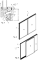
- FIGS 2-15 show different views of the same embodiment of an outwardly opening sliding door assembly according to the invention.
- the sliding door assembly 1 comprises a frame 2, a fixed panel 3 arranged in a first opening in the frame and a sliding panel 4 arranged in a second opening in the frame.
- the frame is mounted in a wall opening (not shown) as is of the kind which is well known in the art.
- the frame comprises four outer frame elements forming the periphery of the frame and a post arranged in the middle of the frame to define two openings in the frame.
- the fixed panel and the sliding panel are assembled from similar extruded sash elements and therefore have similar cross sections.
- the fixed panel is fixed in the first frame opening via fixed fittings while the sliding panel is mounted in the second frame opening via sliding door fittings.
- the person skilled in the art will be familiar with this type of construction and more details will not be provided here.
- the outer surface (the surface which can be seen in the figures) of the fixed panel 3 is in the same plane as the outer surface of the sliding panel 4.
- This provides a harmonious outer visual impression.
- the thickness of the sliding panel and the thickness of the fixed panel are the same, and as such, the inner surfaces (the surfaces facing into the paper in the figures) of the fixed and sliding panels are also arranged in the same plane. This also gives a harmonious visual impression on the inside of the door assembly.
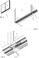
- Figures 4-7 show different views of the bottom of the door assembly in the closed position of the door assembly. In order to show the details of the opening mechanism, the track on which the wagons roll has been removed.
- the opening mechanism comprises two wagons, a side wagon 10 placed at one side of the door assembly and a centre wagon 11 placed near the centre of the door assembly.
- the centre wagon 11 is placed near the side edge of the sliding panel which is closest to a side edge of the fixed panel, which places it near the centre of the door assembly, hence the name "center” wagon.
- Each wagon has a pivotable arm 12,13.
- Each arm is pivotably connected to a wagon and one side edge of the sliding door panel near the bottom of the sliding door panel.
- the arm is connected to the ide edge of the sliding panel at the corner between the side edge and the bottom edge.
- the arm could also be connected to the bottom edge of the sliding panel.
- the arm 12 of the side wagon 10 is connected to the side edge of the sliding panel which is closest to the side edge of the door assembly on the side of the sliding panel and the arm 13 of the centre wagon 11 is connected to the side edge of the sliding panel which is closest the centre of the door assembly.
- the centre wagon 11 and the centre wagon's arm 13 is located underneath the fixed panel 3.
- the side wagon 10 and the side wagon's arm 12 are located underneath the sliding panel 4.
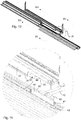
- Figures 8-15 show different views of the door assembly in an open position.
- the sliding panel is first displaced outwardly by rotating the arms 12,13.
- the wagons are both displaced a small amount towards the side edge of the door assembly closest to the sliding panel. In this way, it is possible to move the door almost perpendicularly outwards at the start of the opening procedure.
- it is furthermore arranged such that the centre wagon and centre arm are displaced a small amount more than the side wagon and side arm are displaced at the start of the procedure. In this way, the door is angled slightly.
- this form of opening procedure and opening mechanism is known in the prior art. More details of such mechanisms can be found in the previously cited patent documents.
- a sealing profile 30 has been attached to the inside lowermost edge of the fixed and sliding panels 3,4. This can best be seen in figures 12 and 13 .
- the sealing profile is an extruded elongated profile having an essentially constant cross section perpendicular to the longitudinal axis of the profile.
- the sealing profile 30 is arranged to move the seal 31 between the panel and the sill downwards in comparison to prior art so that the sill height can be reduced.
- the seal 31 can be described as a lower sealing surface which forms a sealing interface between the panel and the sealing surface 23 of the bottom sill 20.
- an opening 32 is formed in the sealing profile 30, to allow the wagon to pass through the sealing profile when the sliding panel is to be displaced outwardly.
- the opening is formed such that an open area having a cross sectional area in a plane parallel to the plane of the sliding panel is large enough for the wagon to slide through the opening.
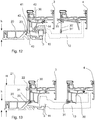
- a sealing plate 40 has been attached to the wagon between the wagon and the sealing surface 23 of the bottom sill 20.
- the sealing plate 40 is arranged to fill the opening 32 in the sealing profile 30 when the sliding panel 4 is put into the closed position of the door assembly.
- the opening 32 in the sealing profile 30 is provided with a sealing edge 33 which is arranged around the periphery of the opening 32.
- the sealing edge is arranged in a plane which is parallel to the plane of the sliding panel.
- the sealing edge 33 is furthermore arranged to correspond to the outer edge 41 of the sealing plate 40. When the sliding panel is closed, the outer edge 41 of the sealing plate 40 is arranged to press up against the sealing edge 33 of the opening 32 in the sealing profile 30.
- the upper outer horizontal edge 42 of the sealing plate forms a vertically arranged sealing surface which engages with the inner upper horizontal edge 34 of the opening of the sliding panel to form an upper sealing interface in the closed position of the assembly.
- the lower inner horizontal edge 43 of the sealing plate forms a vertically arranged sealing surface which engages with the vertically arranged and outwardly facing sealing surface 23 of the bottom sill 20 to form a lower sealing interface in the closed position of the assembly.
- the sealing surfaces are arranged as vertical surfaces which engage with each other by pressing one surface against another.
- Deformable seals for example rubber gaskets, are attached to the sealing surfaces to further improve the sealing effect.
- the sealing plate could be arranged slightly smaller than the opening and be provided with a perimeter seal, for example a wiper seal or an o-ring, which engages with an inner surface of the opening when the sealing plate is inserted into the opening.
- the sealing plate 40 is attached to the wagon in a displaceable manner via two displacement mechanisms.
- a first displacement mechanism 50 is provided to allow the sealing plate 40 to displace in a direction perpendicular to the plane of the sliding panel and a second displacement mechanism 51 is provided to allow the sealing plate 40 to displace in a direction parallel to the plane of the sliding panel.
- the first displacement mechanism 50 allows the sealing plate 40 to retract from the sill 20 when the sliding panel is opened.
- the first displacement mechanism comprises a horizontal slot 52 connected to the wagon and square horizontal rod 53 connected to the outer side of the sealing plate 40.
- the rod 53 is arranged inside the slot 52.
- the rod can displace in the slot but cannot rotate in the slot. In this way, the sealing plate can slide in an out in a direction parallel to the axis of the slot.
- the axis of the slot in the current embodiment is arranged perpendicular to the plane of the sliding panel.
- a spring is provided to bias the sealing plate towards the wagon.
- the sealing plate will also move outwards, thereby releasing the sealing interface between the sealing plate and the bottom sill.
- the closing of the sliding panel will press the sealing plate back in towards the bottom sill thereby re-establishing the sealing interface.
- the second displacement mechanism 51 allows the side wagon 10 to displace slightly sideways before the sliding panel starts to move outwardly. In this way, the wagon can move without requiring that the sealing plate 40 displaces with the wagon at the start of the motion.
- the sideways motion is provided by the same slot 52 and rod 53 arrangement as the first displacement mechanism in the current embodiment.
- the rod is arranged to slide in the opening of the slot in a direction which is parallel to the longitudinal axis of the rod 53.
- a spring 54 is provided to move the sealing plate into a predetermined bias position. In the current embodiment, the spring is arranged to force the sealing plate to one side of the wagon. However, in another embodiment (not shown) another spring arrangement could be provided to bias the sealing plate in a position where motion to both sides was permitted.
- the sealing profile 30 is provided with an opening for the side wagon 10 to pass through the sealing profile. This is because the side wagon is placed underneath the sliding panel 4 in the closed position of the sliding panel. In contrast, since the centre wagon 11 is placed underneath the fixed panel 3 in the closed position of the sliding panel, see for example figure 6 , it is not necessary for the centre wagon 11 to pass through the sealing profile 30. As such only one opening 32 is required in the sealing profile 30 of the sliding panel. Furthermore, as can be roughly seen in figure 9 , the arm 13 of the centre wagon 11 is connected to the side edge of the sliding panel. In this way, the arm does not interfere with the sealing profile since the sealing profile does not extend into the corner region of the sliding panel. This explains why the arm 13 in figure 13 is higher than the sealing profile 30.
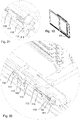
- Figure 18 shows a close-up view of a second embodiment of an assembly 100 according to the current invention.
- the sealing plate was a vertically arranged plate which closed the opening in the sealing profile.
- a second plate element 102 is provided which is attached to the sealing plate 101.
- the sealing plate 101 is arranged as an essentially vertical plate which is sized to close the opening in the sealing profile in the same manner as the sealing plate of the first embodiment.
- the second plate element 102 is arranged as an essentially horizontal plate which extends perpendicularly to the sealing plate 101.
- the second plate element is arranged above the side wagon such that the side wagon is covered by the second plate element 102. In this way, a user is prevented from getting his or her fingers or any other unwanted objects stuck in the mechanism between the sealing plate 101 and the side wagon.
- the second plate element could be considered a form of cover element.
- Figure 18 also shows a portion of a connecting element 103 which connects the side and centre wagon so that the two wagons move in a synchronized manner.
- Figures 20 and 21 show a second way of connecting the sealing plate to the wagon.
- the sealing plate itself has been hidden to show the details of connection.
- the first displacement mechanism is arranged as two spring wire elements 110 and the second displacement element is arranged as a sled 111.
- the sled 111 is provided with two elongated rods 112 arranged parallel to the direction of displacement of the side wagon and displaceably supported in two brackets 113 fixed to the wagon.
- the sled 111 is biased into one position by a coil spring 114.
- the two spring wire elements 110 are arranged essentially parallel to the plane of the door and are arranged as cantilever beams with one end 115 fastened to sled 111 and a second end 116 offset from the first end and unsupported.
- the second end 116 is provided with a mounting plate 117 onto which the sealing plate is mountable.
- the wire spring elements 110 are arranged to allow the second end 116 to displace in a direction essentially perpendicular to the plane of the door.
- the first displacement mechanism comprising the two spring wire elements allows the sealing plate to displace in a direction perpendicular to the plane of the door and the second displacement mechanism allows the sealing plate to displace in a direction parallel to the direction of the wagon motion.
- the first displacement mechanism is arranged as two spring wire elements bent into a C shape, with the free ends of the C shape being held in a fixed arrangement on the sled.
- a spring element could also be imagined.
- a simple spring plate element could be used.
- an arrangement of the first displacement mechanism is provided in the form of two cantilever beams where one end of the beams is connected to the sled and the other end of the beams is free and connected to the sealing element.
- the sealing element is arranged to have the same length as the width of the sliding door panel and in this way, extend all the way across the door opening.
- the bottom sash profile of the fixed panel is provided with space to allow the sealing element to slide into when the sliding panel is opened.
- a schematic example is shown in figure 16 .
- the sealing profile 60 attached to the fixed panel 3 were provided with a slot 61 which was the same size as the sealing plate (not shown in figure 16 , but arranged as in figure 12 but extending across the entire width of the door).
- the sealing plate would displace slightly outwardly to be able to pass by the inside surface 62 of the sealing profile 60 of the fixed panel, and then the sealing plate would slide in under the fixed panel while the sliding panel slides outside of the fixed panel.
- the sealing plate displaces slightly outwardly and downwardly to give more room in the fixed profile.
- the invention can be used for both sliding door assemblies and sliding window assemblies.
- the focus was on sliding doors.
- the person skilled in the art will be able to use the teaching of the current invention and apply it to windows as well.
- an outwardly opening door assembly has been described. The terms used in the description will therefore refer to an outwardly opening assembly.
- the person skilled in the art will be able to understand that when designing an inwardly opening door or window assembly based on the teachings of the current specification, the terms inside and outside will be reversed.
Landscapes
- Engineering & Computer Science (AREA)
- Mechanical Engineering (AREA)
- Civil Engineering (AREA)
- Structural Engineering (AREA)
- Specific Sealing Or Ventilating Devices For Doors And Windows (AREA)
- Wing Frames And Configurations (AREA)
Claims (12)
- Eine sich nach innen oder außen öffnende Schiebetür- oder Schiebefensteranordnung (1), umfassend:a. einen Rahmen (2) mit einer unteren Schwelle (20), wobei die untere Schwelle eine Dichtfläche (23) aufweist,b. einen Schiebeflügel (4), der zwischen einer geöffneten Position und einer geschlossenen Position beweglich ist, wobei der Schiebeflügel eine untere Dichtfläche (31) aufweist, die gegen die Dichtfläche (23) der unteren Schwelle (20) des Rahmens (2) in der geschlossenen Position des Schiebeflügels (4) abgedichtet ist, um eine Dichtungsschnittstelle zwischen der unteren Schwelle und dem Schiebeflügel bereitzustellen,c. einen feststehenden Flügel, der in einer Linie mit dem Schiebeflügel in der geschlossenen Position des Schiebeflügels angeordnet ist, so dass die Außenfläche des feststehenden Flügels in der gleichen Ebene wie die Außenfläche des Schiebeflügels ist und/oder die Innenfläche des feststehenden Flügels in der gleichen Ebene wie die Innenfläche des Schiebeflügels ist,d. eine Schiene (3),e. einen Schlitten (10), der so angeordnet ist, dass er entlang der Schiene verschiebbar ist, undf. einen Verschiebemechanismus (12), der den Schiebeflügel (4) und den Schlitten (10) miteinander verbindet, wobei der Verschiebemechanismus so angeordnet ist, dass der Schiebeflügel in Bezug auf den Schlitten in einer Richtung verschiebbar ist, die eine Vektorkomponente aufweist, die senkrecht zur Ebene des Schiebeflügels ist, so dass der Schiebeflügel in einer sich nach innen öffnenden Anordnung nach innen verschoben wird, bis sich die Außenfläche des Schiebeflügels innerhalb der Innenfläche des feststehenden Flügels befindet, oder in einer sich nach außen öffnenden Anordnung, wobei der Schiebeflügel nach außen verschoben wird, bis die Innenfläche des Schiebeflügels außerhalb der Außenfläche des feststehenden Flügels ist,dadurch gekennzeichnet, dass die Anordnung weiter umfasstg. eine Dichtungsplatte (40), die in der geschlossenen Position des Schiebeflügels:i. zwischen dem Schlitten (10) und der Dichtfläche (23) der unteren Schwelle (20) angeordnet ist,ii. mit einer oberen Dichtfläche (42) bereitgestellt ist, die eine obere Dichtungsschnittstelle zwischen der Dichtungsplatte (40) und dem Schiebeflügel(4) bildet und die einen Abschnitt umfasst, der sich oberhalb der obersten Kante (14) des Schlittens (10) befindet, undiii. mit einer unteren Dichtungsfläche (43) versehen ist, die eine untere Dichtungsschnittstelle zwischen der Dichtungsplatte (40) und der Dichtungsfläche (23) der unteren Schwelle (20) bildet und die einen Abschnitt umfasst, der unterhalb der obersten Kante (14) des Schlittens (10) angeordnet ist,h. und wobei die Dichtungsplatte (40) mit dem Schlitten (10) verbunden ist und sich zusammen mit dem Schlitten verschiebt, wenn sich der Schlitten entlang der Schiene (3) verschiebt.
- Schiebetür- oder Schiebefensteranordnung (1) nach Anspruch 1, dadurch gekennzeichnet, dass die Dichtplatte (40) so angeordnet ist, dass die Ebene der Dichtplatte parallel zur Ebene des Schiebeflügels (4) in der geschlossenen Position der Anordnung verläuft.
- Schiebetür- oder Schiebefensteranordnung (100) nach Anspruch 1 oder 2, dadurch gekennzeichnet, dass die Anordnung weiter ein Abdeckelement (102) umfasst, das mit dem Dichtungsplattenelement (101) verbunden ist, um den Schlitten in der geöffneten Position des Schiebeflügels abzudecken.
- Schiebetür- oder Schiebefensteranordnung (100) nach den Ansprüchen 2 und 3, dadurch gekennzeichnet, dass das Abdeckelement (102) als im Wesentlichen horizontales Plattenelement angeordnet ist, das sich im Wesentlichen senkrecht zum Dichtungsplattenelement (101) erstreckt.
- Schiebetür- oder Schiebefensteranordnung (1) nach einem der Ansprüche 1 bis 4, dadurch gekennzeichnet, dass die Anordnung so angeordnet ist, dass die obere Dichtfläche (42) der Dichtplatte (40) in der geöffneten Position des Schiebeflügels (4) nicht in abdichtendem Kontakt mit dem Schiebeflügel (4) steht.
- Schiebetür- oder Schiebefensteranordnung (1) nach einem der Ansprüche 1-5, dadurch gekennzeichnet, dass die untere Dichtfläche (43) der Dichtungsplatte (40) in der geöffneten Position des Schiebeflügels (4) nicht in abdichtendem Kontakt mit der Dichtfläche (23) der unteren Schwelle (20) steht.
- Schiebetür- oder Schiebefensteranordnung (1) nach einem der Ansprüche 1 bis 6, dadurch gekennzeichnet, dass der Schlitten (10) unterhalb des Schiebeflügels (4) angeordnet ist, wenn die Anordnung geschlossen ist.
- Schiebetür- oder Schiebefensteranordnung (1) nach einem der Ansprüche 1 bis 7, dadurch gekennzeichnet, dass die Anordnung weiter einen Verschiebemechanismus (50, 51) für die Dichtplatte umfasst, der es ermöglicht, die Dichtplatte (40) in Bezug auf den Schlitten (10) in eine Richtung mit einer Vektorkomponente, die parallel zur Achse der Schiene (3) verläuft, und/oder in eine Richtung mit einer Vektorkomponente, die senkrecht zur Ebene des Schiebeflügels (4) verläuft, zu verschieben.
- Schiebetür- oder Schiebefensteranordnung (100) nach Anspruch 8, dadurch gekennzeichnet, dass der Verschiebemechanismus der Dichtplatte ein freitragendes Federelement (110) mit einem ersten Abschnitt (115) umfasst, der so befestigt ist, dass er nicht in einer Richtung senkrecht zur Ebene des Schiebeflügels (4) verschiebbar ist, und einem zweiten Abschnitt (116), der von dem ersten Abschnitt in einer Richtung versetzt ist, die parallel zur Ebene des Schiebeflügels verläuft und nicht gestützt ist, wobei der zweite Abschnitt so angeordnet ist, dass er mit der Dichtplatte verbindbar ist.
- Schiebetür- oder Schiebefensteranordnung (1) nach einem der Ansprüche 1 bis 9, dadurch gekennzeichnet, dass sich die Dichtungsplatte (40) über mehr als 90 % der Breite des Schiebeflügels (4) erstreckt.
- Schiebetür- oder Schiebefensteranordnung (1) nach einem der Ansprüche 1 bis 9, dadurch gekennzeichnet, dass sich die Dichtungsplatte (40) nur über einen Abschnitt der Breite des Schiebeflügels (4) erstreckt.
- Schiebetür- oder Schiebefensteranordnung (1) nach Anspruch 11, dadurch gekennzeichnet, dass der Schiebeflügel weiter ein längliches Dichtungsprofil (30) umfasst, das entlang einer Unterkante des Schiebeflügels fest mit dem Schiebeflügel (4) verbunden oder anderweitig in diesen integriert ist und das mit der unteren Dichtfläche (31) versehen ist, die die Dichtfläche zwischen der Unterkante des Schiebeflügels (4) und der unteren Schwelle (20) bildet, wenn sich der Schiebeflügel in seiner geschlossenen Position befindet, wobei sich zumindest ein Abschnitt der Dichtungsschnittstelle zwischen dem Schlitten (10) und der Dichtfläche (23) der unteren Schwelle (20) und zumindest ein Abschnitt der Dichtungsschnittstelle unterhalb der obersten Kante (14) des Wagens (10) befindet, und wobei das Dichtungsprofil (30) mit einer Öffnung (32) versehen ist, wobei die Öffnung einen Bereich in einer Ebene definiert, die parallel zur Ebene des Schiebeflügels ist und in der Nähe des Schlittens (10) in der geschlossenen Position des Schiebeflügels angeordnet ist, wodurch der Schlitten durch die Öffnung (32) in dem Dichtungsprofil (30) hindurchgehen kann, wenn er den Schiebeflügel (4) aus seiner geschlossenen Position in seine geöffnete Position verschiebt, und wobei die Dichtplatte (40) angeordnet ist, um die Öffnung (32) abzudichten, wenn sich der Schiebeflügel (4) in seiner geschlossenen Position befindet.
Applications Claiming Priority (1)
| Application Number | Priority Date | Filing Date | Title |
|---|---|---|---|
| DKPA201470766A DK178574B1 (en) | 2014-12-05 | 2014-12-05 | Sliding door or window assembly with a low bottom sill height |
Publications (2)
| Publication Number | Publication Date |
|---|---|
| EP3029247A1 EP3029247A1 (de) | 2016-06-08 |
| EP3029247B1 true EP3029247B1 (de) | 2019-06-26 |
Family
ID=54834712
Family Applications (1)
| Application Number | Title | Priority Date | Filing Date |
|---|---|---|---|
| EP15198315.2A Active EP3029247B1 (de) | 2014-12-05 | 2015-12-07 | Schiebetür oder fensteranordnung mit niedriger bodenschwellenhöhe |
Country Status (2)
| Country | Link |
|---|---|
| EP (1) | EP3029247B1 (de) |
| DK (2) | DK178574B1 (de) |
Families Citing this family (8)
| Publication number | Priority date | Publication date | Assignee | Title |
|---|---|---|---|---|
| DK179236B9 (en) * | 2016-11-24 | 2018-04-30 | Vkr Holding As | Sliding door or window assembly with a sliding center post bar |
| CN115263147B (zh) * | 2022-01-28 | 2025-12-19 | 沧州凌硕装饰工程有限公司 | 一种外形平齐的隔热防尘漂移窗 |
| CN114809871B (zh) * | 2022-04-27 | 2023-09-29 | 徐州智誉建筑装饰工程有限公司 | 一种便于清灰的环保型塑钢门窗及其使用方法 |
| AT526235B1 (de) * | 2023-04-12 | 2024-01-15 | Kdm Innovation Gmbh | Scharnier zur bewegbaren Lagerung eines Abdeckelementes |
| AT526334B1 (de) * | 2023-04-12 | 2024-02-15 | Kdm Innovation Gmbh | Profil für wenigstens ein Abdeckelement |
| AT526423B1 (de) * | 2023-04-12 | 2024-03-15 | Kdm Innovation Gmbh | Anordnung mit Struktur, Abdeckelement und Führungssystem |
| CN116624072B (zh) * | 2023-07-26 | 2023-10-27 | 广东科腾幕墙有限公司 | 一种便于拆装的装配式门窗及其控制方法 |
| CN118390940B (zh) * | 2024-06-26 | 2024-09-03 | 武汉邢仪新未来电力科技股份有限公司 | 太阳能复合系统及其生产工艺 |
Citations (2)
| Publication number | Priority date | Publication date | Assignee | Title |
|---|---|---|---|---|
| DE2648344A1 (de) * | 1976-10-26 | 1978-05-03 | Rudolf Weikert | Beschlag fuer schiebefenster, schiebetueren u.dgl. |
| EP0916794A2 (de) * | 1997-11-11 | 1999-05-19 | VELUX Industri A/S | Schiebefenster- oder Türanordnung |
Family Cites Families (7)
| Publication number | Priority date | Publication date | Assignee | Title |
|---|---|---|---|---|
| DE3212246C2 (de) * | 1982-04-02 | 1985-09-05 | Gretsch-Unitas GmbH Baubeschläge, 7257 Ditzingen | Beschlag für einen in eine Parallelabstellage bringbaren Flügel einer Tür, eines Fensters od.dgl. |
| EP0443307A1 (de) * | 1990-02-20 | 1991-08-28 | Lindpointner Tore Gesellschaft M.B.H. | Schiebetor |
| DE9305261U1 (de) * | 1993-04-06 | 1993-06-17 | W. Hautau GmbH, 3068 Helpsen | Schiebeflügelbeschlag mit unrundem Führungszapfen |
| DE102005001911A1 (de) * | 2005-01-14 | 2006-07-20 | SCHÜCO International KG | Schiebefenster |
| US8074699B2 (en) * | 2008-09-12 | 2011-12-13 | La Cantina Doors, Inc. | Zero step sill extruded flush threshold door seal system |
| KR101348488B1 (ko) * | 2010-10-27 | 2014-01-07 | (주)엘지하우시스 | 수평밀착창호 |
| DE102014205287A1 (de) * | 2014-03-21 | 2015-09-24 | Roto Frank Ag | Schiebefenster oder Schiebetür mit einem Dichtelement |
-
2014
- 2014-12-05 DK DKPA201470766A patent/DK178574B1/en not_active IP Right Cessation
-
2015
- 2015-12-07 EP EP15198315.2A patent/EP3029247B1/de active Active
- 2015-12-07 DK DK15198315.2T patent/DK3029247T3/da active
Patent Citations (2)
| Publication number | Priority date | Publication date | Assignee | Title |
|---|---|---|---|---|
| DE2648344A1 (de) * | 1976-10-26 | 1978-05-03 | Rudolf Weikert | Beschlag fuer schiebefenster, schiebetueren u.dgl. |
| EP0916794A2 (de) * | 1997-11-11 | 1999-05-19 | VELUX Industri A/S | Schiebefenster- oder Türanordnung |
Also Published As
| Publication number | Publication date |
|---|---|
| DK178574B1 (en) | 2016-07-04 |
| DK201470766A1 (en) | 2016-06-27 |
| DK3029247T3 (da) | 2019-08-26 |
| EP3029247A1 (de) | 2016-06-08 |
Similar Documents
| Publication | Publication Date | Title |
|---|---|---|
| EP3029247B1 (de) | Schiebetür oder fensteranordnung mit niedriger bodenschwellenhöhe | |
| KR101520149B1 (ko) | 이중 개폐구조를 갖는 미서기 창호 | |
| CA2988015A1 (en) | Expanding window covering | |
| US7716875B2 (en) | Windows | |
| US20100012279A1 (en) | Louvred Shutter | |
| US9909359B2 (en) | Covering device | |
| CA2588978C (en) | Window assembly with movable interior sash | |
| EP3071775B1 (de) | Unsichtbarer fensterrahmen | |
| CN204023854U (zh) | 一种侧向通风式玻璃幕墙系统 | |
| EP2213826A1 (de) | Verbundfensterflügel für Fenster und Fenstertüren mit entsprechendem Stockprofil | |
| US20230358092A1 (en) | Projecting, compression seal, window designs | |
| WO2010098688A1 (en) | Balcony glazing system without vertical frame members | |
| WO2005028793A1 (en) | Window or door structure with a locking tap | |
| CN210659714U (zh) | 一种玻璃幕墙窗的地弹门 | |
| EP3953554B1 (de) | Schiebefensteranordnung und verwendung davon zur verglasung einer balkoneinheit | |
| JP5107658B2 (ja) | シャッター装置のガイドレール、及び、それを備えるシャッター装置 | |
| DK179236B9 (en) | Sliding door or window assembly with a sliding center post bar | |
| DE102015114424A1 (de) | Rahmenadapter, Fenstereinsatz mit einem Rahmenadapter und Fahrzeug mit einem Rahmenadapter | |
| KR102629333B1 (ko) | 기밀성능이 구비된 방재 창호 구조 | |
| NZ583779A (en) | Window and door frames and sashes lined with insulating thermoplastic layer | |
| JP6652435B2 (ja) | 建具 | |
| CN113846957B (zh) | 一种适用于推拉式窗户的隐形纱窗 | |
| EP4006253B1 (de) | Dachfenster umfassend einen flügel mit aufklappbarem äusseren wetterschutzschild | |
| EP1643069A2 (de) | Rahmen für Fenster, Fenstertüren und dergleichen | |
| CN210888507U (zh) | 一种窗户连接件及窗户 |
Legal Events
| Date | Code | Title | Description |
|---|---|---|---|
| PUAI | Public reference made under article 153(3) epc to a published international application that has entered the european phase |
Free format text: ORIGINAL CODE: 0009012 |
|
| AK | Designated contracting states |
Kind code of ref document: A1 Designated state(s): AL AT BE BG CH CY CZ DE DK EE ES FI FR GB GR HR HU IE IS IT LI LT LU LV MC MK MT NL NO PL PT RO RS SE SI SK SM TR |
|
| AX | Request for extension of the european patent |
Extension state: BA ME |
|
| STAA | Information on the status of an ep patent application or granted ep patent |
Free format text: STATUS: REQUEST FOR EXAMINATION WAS MADE |
|
| 17P | Request for examination filed |
Effective date: 20161208 |
|
| RBV | Designated contracting states (corrected) |
Designated state(s): AL AT BE BG CH CY CZ DE DK EE ES FI FR GB GR HR HU IE IS IT LI LT LU LV MC MK MT NL NO PL PT RO RS SE SI SK SM TR |
|
| STAA | Information on the status of an ep patent application or granted ep patent |
Free format text: STATUS: EXAMINATION IS IN PROGRESS |
|
| 17Q | First examination report despatched |
Effective date: 20170717 |
|
| GRAP | Despatch of communication of intention to grant a patent |
Free format text: ORIGINAL CODE: EPIDOSNIGR1 |
|
| STAA | Information on the status of an ep patent application or granted ep patent |
Free format text: STATUS: GRANT OF PATENT IS INTENDED |
|
| INTG | Intention to grant announced |
Effective date: 20190104 |
|
| GRAS | Grant fee paid |
Free format text: ORIGINAL CODE: EPIDOSNIGR3 |
|
| GRAA | (expected) grant |
Free format text: ORIGINAL CODE: 0009210 |
|
| STAA | Information on the status of an ep patent application or granted ep patent |
Free format text: STATUS: THE PATENT HAS BEEN GRANTED |
|
| AK | Designated contracting states |
Kind code of ref document: B1 Designated state(s): AL AT BE BG CH CY CZ DE DK EE ES FI FR GB GR HR HU IE IS IT LI LT LU LV MC MK MT NL NO PL PT RO RS SE SI SK SM TR |
|
| REG | Reference to a national code |
Ref country code: GB Ref legal event code: FG4D |
|
| REG | Reference to a national code |
Ref country code: CH Ref legal event code: EP |
|
| REG | Reference to a national code |
Ref country code: AT Ref legal event code: REF Ref document number: 1148479 Country of ref document: AT Kind code of ref document: T Effective date: 20190715 |
|
| REG | Reference to a national code |
Ref country code: DE Ref legal event code: R096 Ref document number: 602015032625 Country of ref document: DE |
|
| REG | Reference to a national code |
Ref country code: IE Ref legal event code: FG4D |
|
| REG | Reference to a national code |
Ref country code: DK Ref legal event code: T3 Effective date: 20190823 |
|
| REG | Reference to a national code |
Ref country code: SE Ref legal event code: TRGR |
|
| REG | Reference to a national code |
Ref country code: NL Ref legal event code: MP Effective date: 20190626 |
|
| PG25 | Lapsed in a contracting state [announced via postgrant information from national office to epo] |
Ref country code: LT Free format text: LAPSE BECAUSE OF FAILURE TO SUBMIT A TRANSLATION OF THE DESCRIPTION OR TO PAY THE FEE WITHIN THE PRESCRIBED TIME-LIMIT Effective date: 20190626 Ref country code: FI Free format text: LAPSE BECAUSE OF FAILURE TO SUBMIT A TRANSLATION OF THE DESCRIPTION OR TO PAY THE FEE WITHIN THE PRESCRIBED TIME-LIMIT Effective date: 20190626 Ref country code: NO Free format text: LAPSE BECAUSE OF FAILURE TO SUBMIT A TRANSLATION OF THE DESCRIPTION OR TO PAY THE FEE WITHIN THE PRESCRIBED TIME-LIMIT Effective date: 20190926 Ref country code: AL Free format text: LAPSE BECAUSE OF FAILURE TO SUBMIT A TRANSLATION OF THE DESCRIPTION OR TO PAY THE FEE WITHIN THE PRESCRIBED TIME-LIMIT Effective date: 20190626 Ref country code: HR Free format text: LAPSE BECAUSE OF FAILURE TO SUBMIT A TRANSLATION OF THE DESCRIPTION OR TO PAY THE FEE WITHIN THE PRESCRIBED TIME-LIMIT Effective date: 20190626 |
|
| REG | Reference to a national code |
Ref country code: LT Ref legal event code: MG4D |
|
| PG25 | Lapsed in a contracting state [announced via postgrant information from national office to epo] |
Ref country code: BG Free format text: LAPSE BECAUSE OF FAILURE TO SUBMIT A TRANSLATION OF THE DESCRIPTION OR TO PAY THE FEE WITHIN THE PRESCRIBED TIME-LIMIT Effective date: 20190926 Ref country code: GR Free format text: LAPSE BECAUSE OF FAILURE TO SUBMIT A TRANSLATION OF THE DESCRIPTION OR TO PAY THE FEE WITHIN THE PRESCRIBED TIME-LIMIT Effective date: 20190927 Ref country code: LV Free format text: LAPSE BECAUSE OF FAILURE TO SUBMIT A TRANSLATION OF THE DESCRIPTION OR TO PAY THE FEE WITHIN THE PRESCRIBED TIME-LIMIT Effective date: 20190626 Ref country code: RS Free format text: LAPSE BECAUSE OF FAILURE TO SUBMIT A TRANSLATION OF THE DESCRIPTION OR TO PAY THE FEE WITHIN THE PRESCRIBED TIME-LIMIT Effective date: 20190626 |
|
| REG | Reference to a national code |
Ref country code: AT Ref legal event code: MK05 Ref document number: 1148479 Country of ref document: AT Kind code of ref document: T Effective date: 20190626 |
|
| PG25 | Lapsed in a contracting state [announced via postgrant information from national office to epo] |
Ref country code: EE Free format text: LAPSE BECAUSE OF FAILURE TO SUBMIT A TRANSLATION OF THE DESCRIPTION OR TO PAY THE FEE WITHIN THE PRESCRIBED TIME-LIMIT Effective date: 20190626 Ref country code: AT Free format text: LAPSE BECAUSE OF FAILURE TO SUBMIT A TRANSLATION OF THE DESCRIPTION OR TO PAY THE FEE WITHIN THE PRESCRIBED TIME-LIMIT Effective date: 20190626 Ref country code: NL Free format text: LAPSE BECAUSE OF FAILURE TO SUBMIT A TRANSLATION OF THE DESCRIPTION OR TO PAY THE FEE WITHIN THE PRESCRIBED TIME-LIMIT Effective date: 20190626 Ref country code: CZ Free format text: LAPSE BECAUSE OF FAILURE TO SUBMIT A TRANSLATION OF THE DESCRIPTION OR TO PAY THE FEE WITHIN THE PRESCRIBED TIME-LIMIT Effective date: 20190626 Ref country code: RO Free format text: LAPSE BECAUSE OF FAILURE TO SUBMIT A TRANSLATION OF THE DESCRIPTION OR TO PAY THE FEE WITHIN THE PRESCRIBED TIME-LIMIT Effective date: 20190626 Ref country code: PT Free format text: LAPSE BECAUSE OF FAILURE TO SUBMIT A TRANSLATION OF THE DESCRIPTION OR TO PAY THE FEE WITHIN THE PRESCRIBED TIME-LIMIT Effective date: 20191028 Ref country code: SK Free format text: LAPSE BECAUSE OF FAILURE TO SUBMIT A TRANSLATION OF THE DESCRIPTION OR TO PAY THE FEE WITHIN THE PRESCRIBED TIME-LIMIT Effective date: 20190626 |
|
| PG25 | Lapsed in a contracting state [announced via postgrant information from national office to epo] |
Ref country code: IS Free format text: LAPSE BECAUSE OF FAILURE TO SUBMIT A TRANSLATION OF THE DESCRIPTION OR TO PAY THE FEE WITHIN THE PRESCRIBED TIME-LIMIT Effective date: 20191026 Ref country code: IT Free format text: LAPSE BECAUSE OF FAILURE TO SUBMIT A TRANSLATION OF THE DESCRIPTION OR TO PAY THE FEE WITHIN THE PRESCRIBED TIME-LIMIT Effective date: 20190626 Ref country code: SM Free format text: LAPSE BECAUSE OF FAILURE TO SUBMIT A TRANSLATION OF THE DESCRIPTION OR TO PAY THE FEE WITHIN THE PRESCRIBED TIME-LIMIT Effective date: 20190626 Ref country code: ES Free format text: LAPSE BECAUSE OF FAILURE TO SUBMIT A TRANSLATION OF THE DESCRIPTION OR TO PAY THE FEE WITHIN THE PRESCRIBED TIME-LIMIT Effective date: 20190626 |
|
| PG25 | Lapsed in a contracting state [announced via postgrant information from national office to epo] |
Ref country code: TR Free format text: LAPSE BECAUSE OF FAILURE TO SUBMIT A TRANSLATION OF THE DESCRIPTION OR TO PAY THE FEE WITHIN THE PRESCRIBED TIME-LIMIT Effective date: 20190626 |
|
| PG25 | Lapsed in a contracting state [announced via postgrant information from national office to epo] |
Ref country code: PL Free format text: LAPSE BECAUSE OF FAILURE TO SUBMIT A TRANSLATION OF THE DESCRIPTION OR TO PAY THE FEE WITHIN THE PRESCRIBED TIME-LIMIT Effective date: 20190626 |
|
| PG25 | Lapsed in a contracting state [announced via postgrant information from national office to epo] |
Ref country code: IS Free format text: LAPSE BECAUSE OF FAILURE TO SUBMIT A TRANSLATION OF THE DESCRIPTION OR TO PAY THE FEE WITHIN THE PRESCRIBED TIME-LIMIT Effective date: 20200224 |
|
| REG | Reference to a national code |
Ref country code: DE Ref legal event code: R097 Ref document number: 602015032625 Country of ref document: DE |
|
| PLBE | No opposition filed within time limit |
Free format text: ORIGINAL CODE: 0009261 |
|
| STAA | Information on the status of an ep patent application or granted ep patent |
Free format text: STATUS: NO OPPOSITION FILED WITHIN TIME LIMIT |
|
| PG2D | Information on lapse in contracting state deleted |
Ref country code: IS |
|
| REG | Reference to a national code |
Ref country code: CH Ref legal event code: PL |
|
| 26N | No opposition filed |
Effective date: 20200603 |
|
| REG | Reference to a national code |
Ref country code: BE Ref legal event code: MM Effective date: 20191231 |
|
| PG25 | Lapsed in a contracting state [announced via postgrant information from national office to epo] |
Ref country code: SI Free format text: LAPSE BECAUSE OF FAILURE TO SUBMIT A TRANSLATION OF THE DESCRIPTION OR TO PAY THE FEE WITHIN THE PRESCRIBED TIME-LIMIT Effective date: 20190626 Ref country code: MC Free format text: LAPSE BECAUSE OF FAILURE TO SUBMIT A TRANSLATION OF THE DESCRIPTION OR TO PAY THE FEE WITHIN THE PRESCRIBED TIME-LIMIT Effective date: 20190626 |
|
| PG25 | Lapsed in a contracting state [announced via postgrant information from national office to epo] |
Ref country code: FR Free format text: LAPSE BECAUSE OF NON-PAYMENT OF DUE FEES Effective date: 20191231 Ref country code: IE Free format text: LAPSE BECAUSE OF NON-PAYMENT OF DUE FEES Effective date: 20191207 Ref country code: LU Free format text: LAPSE BECAUSE OF NON-PAYMENT OF DUE FEES Effective date: 20191207 |
|
| PG25 | Lapsed in a contracting state [announced via postgrant information from national office to epo] |
Ref country code: CH Free format text: LAPSE BECAUSE OF NON-PAYMENT OF DUE FEES Effective date: 20191231 Ref country code: BE Free format text: LAPSE BECAUSE OF NON-PAYMENT OF DUE FEES Effective date: 20191231 Ref country code: LI Free format text: LAPSE BECAUSE OF NON-PAYMENT OF DUE FEES Effective date: 20191231 |
|
| PG25 | Lapsed in a contracting state [announced via postgrant information from national office to epo] |
Ref country code: CY Free format text: LAPSE BECAUSE OF FAILURE TO SUBMIT A TRANSLATION OF THE DESCRIPTION OR TO PAY THE FEE WITHIN THE PRESCRIBED TIME-LIMIT Effective date: 20190626 |
|
| PG25 | Lapsed in a contracting state [announced via postgrant information from national office to epo] |
Ref country code: MT Free format text: LAPSE BECAUSE OF FAILURE TO SUBMIT A TRANSLATION OF THE DESCRIPTION OR TO PAY THE FEE WITHIN THE PRESCRIBED TIME-LIMIT Effective date: 20190626 Ref country code: HU Free format text: LAPSE BECAUSE OF FAILURE TO SUBMIT A TRANSLATION OF THE DESCRIPTION OR TO PAY THE FEE WITHIN THE PRESCRIBED TIME-LIMIT; INVALID AB INITIO Effective date: 20151207 |
|
| PG25 | Lapsed in a contracting state [announced via postgrant information from national office to epo] |
Ref country code: MK Free format text: LAPSE BECAUSE OF FAILURE TO SUBMIT A TRANSLATION OF THE DESCRIPTION OR TO PAY THE FEE WITHIN THE PRESCRIBED TIME-LIMIT Effective date: 20190626 |
|
| PGFP | Annual fee paid to national office [announced via postgrant information from national office to epo] |
Ref country code: DE Payment date: 20251104 Year of fee payment: 11 |
|
| PGFP | Annual fee paid to national office [announced via postgrant information from national office to epo] |
Ref country code: GB Payment date: 20251114 Year of fee payment: 11 |
|
| PGFP | Annual fee paid to national office [announced via postgrant information from national office to epo] |
Ref country code: DK Payment date: 20251212 Year of fee payment: 11 |
|
| PGFP | Annual fee paid to national office [announced via postgrant information from national office to epo] |
Ref country code: SE Payment date: 20251112 Year of fee payment: 11 |