EP3032045A1 - Système antigivrage de nacelle de moteur à turbine à gaz - Google Patents
Système antigivrage de nacelle de moteur à turbine à gaz Download PDFInfo
- Publication number
- EP3032045A1 EP3032045A1 EP15197690.9A EP15197690A EP3032045A1 EP 3032045 A1 EP3032045 A1 EP 3032045A1 EP 15197690 A EP15197690 A EP 15197690A EP 3032045 A1 EP3032045 A1 EP 3032045A1
- Authority
- EP
- European Patent Office
- Prior art keywords
- coolant
- gas turbine
- turbine engine
- heat exchanger
- passageway
- Prior art date
- Legal status (The legal status is an assumption and is not a legal conclusion. Google has not performed a legal analysis and makes no representation as to the accuracy of the status listed.)
- Granted
Links
Images

Classifications
-
- F—MECHANICAL ENGINEERING; LIGHTING; HEATING; WEAPONS; BLASTING
- F02—COMBUSTION ENGINES; HOT-GAS OR COMBUSTION-PRODUCT ENGINE PLANTS
- F02C—GAS-TURBINE PLANTS; AIR INTAKES FOR JET-PROPULSION PLANTS; CONTROLLING FUEL SUPPLY IN AIR-BREATHING JET-PROPULSION PLANTS
- F02C7/00—Features, components parts, details or accessories, not provided for in, or of interest apart form groups F02C1/00 - F02C6/00; Air intakes for jet-propulsion plants
- F02C7/04—Air intakes for gas-turbine plants or jet-propulsion plants
- F02C7/047—Heating to prevent icing
-
- B—PERFORMING OPERATIONS; TRANSPORTING
- B64—AIRCRAFT; AVIATION; COSMONAUTICS
- B64D—EQUIPMENT FOR FITTING IN OR TO AIRCRAFT; FLIGHT SUITS; PARACHUTES; ARRANGEMENT OR MOUNTING OF POWER PLANTS OR PROPULSION TRANSMISSIONS IN AIRCRAFT
- B64D33/00—Arrangement in aircraft of power plant parts or auxiliaries not otherwise provided for
- B64D33/02—Arrangement in aircraft of power plant parts or auxiliaries not otherwise provided for of combustion air intakes
-
- F—MECHANICAL ENGINEERING; LIGHTING; HEATING; WEAPONS; BLASTING
- F01—MACHINES OR ENGINES IN GENERAL; ENGINE PLANTS IN GENERAL; STEAM ENGINES
- F01D—NON-POSITIVE DISPLACEMENT MACHINES OR ENGINES, e.g. STEAM TURBINES
- F01D25/00—Component parts, details, or accessories, not provided for in, or of interest apart from, other groups
- F01D25/02—De-icing means for engines having icing phenomena
-
- F—MECHANICAL ENGINEERING; LIGHTING; HEATING; WEAPONS; BLASTING
- F02—COMBUSTION ENGINES; HOT-GAS OR COMBUSTION-PRODUCT ENGINE PLANTS
- F02C—GAS-TURBINE PLANTS; AIR INTAKES FOR JET-PROPULSION PLANTS; CONTROLLING FUEL SUPPLY IN AIR-BREATHING JET-PROPULSION PLANTS
- F02C7/00—Features, components parts, details or accessories, not provided for in, or of interest apart form groups F02C1/00 - F02C6/00; Air intakes for jet-propulsion plants
- F02C7/12—Cooling of plants
- F02C7/14—Cooling of plants of fluids in the plant, e.g. lubricant or fuel
-
- F—MECHANICAL ENGINEERING; LIGHTING; HEATING; WEAPONS; BLASTING
- F02—COMBUSTION ENGINES; HOT-GAS OR COMBUSTION-PRODUCT ENGINE PLANTS
- F02K—JET-PROPULSION PLANTS
- F02K3/00—Plants including a gas turbine driving a compressor or a ducted fan
- F02K3/02—Plants including a gas turbine driving a compressor or a ducted fan in which part of the working fluid by-passes the turbine and combustion chamber
- F02K3/04—Plants including a gas turbine driving a compressor or a ducted fan in which part of the working fluid by-passes the turbine and combustion chamber the plant including ducted fans, i.e. fans with high volume, low pressure outputs, for augmenting the jet thrust, e.g. of double-flow type
- F02K3/06—Plants including a gas turbine driving a compressor or a ducted fan in which part of the working fluid by-passes the turbine and combustion chamber the plant including ducted fans, i.e. fans with high volume, low pressure outputs, for augmenting the jet thrust, e.g. of double-flow type with front fan
-
- B—PERFORMING OPERATIONS; TRANSPORTING
- B64—AIRCRAFT; AVIATION; COSMONAUTICS
- B64D—EQUIPMENT FOR FITTING IN OR TO AIRCRAFT; FLIGHT SUITS; PARACHUTES; ARRANGEMENT OR MOUNTING OF POWER PLANTS OR PROPULSION TRANSMISSIONS IN AIRCRAFT
- B64D33/00—Arrangement in aircraft of power plant parts or auxiliaries not otherwise provided for
- B64D33/02—Arrangement in aircraft of power plant parts or auxiliaries not otherwise provided for of combustion air intakes
- B64D2033/0233—Arrangement in aircraft of power plant parts or auxiliaries not otherwise provided for of combustion air intakes comprising de-icing means
-
- B—PERFORMING OPERATIONS; TRANSPORTING
- B64—AIRCRAFT; AVIATION; COSMONAUTICS
- B64D—EQUIPMENT FOR FITTING IN OR TO AIRCRAFT; FLIGHT SUITS; PARACHUTES; ARRANGEMENT OR MOUNTING OF POWER PLANTS OR PROPULSION TRANSMISSIONS IN AIRCRAFT
- B64D33/00—Arrangement in aircraft of power plant parts or auxiliaries not otherwise provided for
- B64D33/02—Arrangement in aircraft of power plant parts or auxiliaries not otherwise provided for of combustion air intakes
- B64D2033/0266—Arrangement in aircraft of power plant parts or auxiliaries not otherwise provided for of combustion air intakes specially adapted for particular type of power plants
- B64D2033/0286—Arrangement in aircraft of power plant parts or auxiliaries not otherwise provided for of combustion air intakes specially adapted for particular type of power plants for turbofan engines
-
- F—MECHANICAL ENGINEERING; LIGHTING; HEATING; WEAPONS; BLASTING
- F05—INDEXING SCHEMES RELATING TO ENGINES OR PUMPS IN VARIOUS SUBCLASSES OF CLASSES F01-F04
- F05D—INDEXING SCHEME FOR ASPECTS RELATING TO NON-POSITIVE-DISPLACEMENT MACHINES OR ENGINES, GAS-TURBINES OR JET-PROPULSION PLANTS
- F05D2260/00—Function
- F05D2260/20—Heat transfer, e.g. cooling
- F05D2260/207—Heat transfer, e.g. cooling using a phase changing mass, e.g. heat absorbing by melting or boiling
-
- Y—GENERAL TAGGING OF NEW TECHNOLOGICAL DEVELOPMENTS; GENERAL TAGGING OF CROSS-SECTIONAL TECHNOLOGIES SPANNING OVER SEVERAL SECTIONS OF THE IPC; TECHNICAL SUBJECTS COVERED BY FORMER USPC CROSS-REFERENCE ART COLLECTIONS [XRACs] AND DIGESTS
- Y02—TECHNOLOGIES OR APPLICATIONS FOR MITIGATION OR ADAPTATION AGAINST CLIMATE CHANGE
- Y02T—CLIMATE CHANGE MITIGATION TECHNOLOGIES RELATED TO TRANSPORTATION
- Y02T50/00—Aeronautics or air transport
- Y02T50/60—Efficient propulsion technologies, e.g. for aircraft
Definitions
- This disclosure relates to a gas turbine engine de-icing system used, for example, for a fan nacelle.
- a gas turbine engine typically includes a fan section, a compressor section, a combustor section and a turbine section. Air entering the compressor section is compressed and delivered into the combustor section where it is mixed with fuel and ignited to generate a high-speed exhaust gas flow. The high-speed exhaust gas flow expands through the turbine section to drive the compressor and the fan section.
- the compressor section typically includes low and high pressure compressors, and the turbine section includes low and high pressure turbines.
- Gas turbine engine inlet components such as the fan nacelle, are subject to icing during some engine operating conditions. Ice accumulation at the engine inlet can adversely impact engine operation. To this end, de-icing systems are used to melt any ice on the engine's inlet surfaces.
- One example de-icing system uses electrically operated resistive elements embedded in the nacelle inlet walls. These resistive elements are powered by a generator driven by the engine. The generators must be sized to power the resistive elements, which represent a parasitic load on the engine.
- Another example de-icing system uses a spray ring arranged in a D-duct, which provides the inlet surface of the fan nacelle. Bleed air from the compressor section is provided to the spray ring to direct hot air onto the inlet wall. Since work has already been done to this hot air by the compressor section, engine efficiency is reduced.
- a gas turbine engine de-icing system includes a heat exchanger and a coolant loop that is in fluid communication with the heat exchanger and is configured to circulate a coolant.
- An engine oil loop is in fluid communication with the heat exchanger and is configured to transfer heat to the coolant.
- a gas turbine engine inlet structure includes a cavity.
- a manifold is arranged in the cavity and is in fluid communication with the coolant loop. The manifold is configured to spray the coolant onto the gas turbine engine inlet structure to de-ice the gas turbine engine inlet structure.
- the heat exchanger is arranged in a passageway and is configured to be exposed to an airflow.
- a fan nacelle and a core nacelle that provide a bypass flow path.
- the passageway is in fluid communication with the bypass flow path.
- a door is arranged in the passageway.
- a controller is configured to operatively communicate with the door to selectively regulate the airflow through the passageway.
- the coolant is a phase change fluid.
- the coolant changes phase from a liquid to a gas or saturated vapor in a range of 200°F-500°F (93°C-260°C).
- the gas turbine engine inlet structure is a fan nacelle and the manifold is an annular spray bar that is arranged in the fan nacelle.
- the coolant loop includes a reservoir and a pump that is configured to circulate the coolant.
- the reservoir is arranged downstream from the manifold and is configured to collect the liquid.
- At least one of a gearbox and bearing system is in fluid communication with the engine oil loop.
- the gearbox operatively connects a turbine section to a fan section.
- a method of de-icing a gas turbine engine component comprising the steps of circulating an engine oil to a heat exchanger, rejecting heat from the engine oil to a coolant, circulating the coolant to an gas turbine engine inlet component and de-icing the gas turbine engine inlet component with the coolant.
- the engine oil circulating step includes pumping the engine oil from at least one of a gearbox and bearing system.
- the heat exchanger is arranged in a passageway and the method comprises the step of providing an airflow through the passageway to cool the engine oil.
- the method includes the step of regulating the airflow through the passageway based upon a desired heat transfer within the heat exchanger.
- the coolant is a phase change fluid.
- the method may further comprise the step of spraying gaseous or saturated vapor coolant onto the gas turbine engine inlet component to de-ice the gas turbine engine inlet component and condensing the gaseous or saturated vapor coolant to a liquid coolant with the de-iced gas turbine engine inlet component.
- the method includes the step of collecting the condensed liquid coolant in a reservoir.
- a gas turbine engine de-icing system in another exemplary embodiment, includes a fan nacelle and a core nacelle that provide a bypass flow path.
- the fan nacelle includes a cavity, a turbine section and a fan section operatively connected by a gearbox.
- a passageway is configured to be exposed to an airflow from the bypass flow path.
- a heat exchanger and a coolant loop is in fluid communication with the heat exchanger and is configured to circulate a coolant.
- An engine oil loop is in fluid communication with the heat exchanger and is configured to transfer heat to the coolant.
- the gearbox is arranged in the engine oil loop.
- a manifold is arranged in the cavity and is in fluid communication with the coolant loop. The manifold is configured to spray the coolant onto the gas turbine engine inlet structure to de-ice the fan nacelle.
- a door is arranged in the passageway.
- a controller is configured to operatively communicate with the door to selectively regulate the airflow through the passageway.
- the coolant is a phase change fluid.
- the coolant changes phase from a liquid to a gas in a range of 200°F-500°F (93°C-260°C).
- FIG. 1 schematically illustrates a gas turbine engine 20.
- the gas turbine engine 20 is disclosed herein as a two-spool turbofan that generally incorporates a fan section 22, a compressor section 24, a combustor section 26 and a turbine section 28.
- Alternative engines might include an augmenter section (not shown) among other systems or features.
- the fan section 22 drives air along a bypass flow path B in a bypass duct 15 defined within a nacelle, while the compressor section 24 drives air along a core flow path C for compression and communication into the combustor section 26 then expansion through the turbine section 28.
- the exemplary engine 20 generally includes a low speed spool 30 and a high speed spool 32 mounted for rotation about an engine central longitudinal axis X relative to an engine static structure 36 via several bearing systems 38. It should be understood that various bearing systems 38 at various locations may alternatively or additionally be provided, and the location of bearing systems 38 may be varied as appropriate to the application.
- the low speed spool 30 generally includes an inner shaft 40 that interconnects a fan 42, a first (or low) pressure compressor 44 and a first (or low) pressure turbine 46.
- the inner shaft 40 is connected to the fan 42 through a speed change mechanism, which in exemplary gas turbine engine 20 is illustrated as a geared architecture 48 to drive the fan 42 at a lower speed than the low speed spool 30.
- the high speed spool 32 includes an outer shaft 50 that interconnects a second (or high) pressure compressor 52 and a second (or high) pressure turbine 54.
- a combustor 56 is arranged in exemplary gas turbine 20 between the high pressure compressor 52 and the high pressure turbine 54.
- a mid-turbine frame 57 of the engine static structure 36 is arranged generally between the high pressure turbine 54 and the low pressure turbine 46.
- the mid-turbine frame 57 further supports bearing systems 38 in the turbine section 28.
- the inner shaft 40 and the outer shaft 50 are concentric and rotate via bearing systems 38 about the engine central longitudinal axis X which is collinear with their longitudinal axes.
- the core airflow is compressed by the low pressure compressor 44 then the high pressure compressor 52, mixed and burned with fuel in the combustor 56, then expanded over the high pressure turbine 54 and low pressure turbine 46.
- the mid-turbine frame 57 includes airfoils 59 which are in the core airflow path C.
- the turbines 46, 54 rotationally drive the respective low speed spool 30 and high speed spool 32 in response to the expansion.
- gear system 48 may be located aft of combustor section 26 or even aft of turbine section 28, and fan section 22 may be positioned forward or aft of the location of gear system 48.
- the engine 20 in one example is a high-bypass geared aircraft engine.
- the engine 20 bypass ratio is greater than about six (6), with an example embodiment being greater than about ten (10)
- the geared architecture 48 is an epicyclic gear train, such as a planetary gear system or other gear system, with a gear reduction ratio of greater than about 2.3
- the low pressure turbine 46 has a pressure ratio that is greater than about five.
- the engine 20 bypass ratio is greater than about ten (10:1)
- the fan diameter is significantly larger than that of the low pressure compressor 44
- the low pressure turbine 46 has a pressure ratio that is greater than about five 5:1.
- Low pressure turbine 46 pressure ratio is pressure measured prior to inlet of low pressure turbine 46 as related to the pressure at the outlet of the low pressure turbine 46 prior to an exhaust nozzle.
- the geared architecture 48 may be an epicycle gear train, such as a planetary gear system or other gear system, with a gear reduction ratio of greater than about 2.3:1. It should be understood, however, that the above parameters are only exemplary of one embodiment of a geared architecture engine and that the present invention is applicable to other gas turbine engines including direct drive turbofans.
- the fan section 22 of the engine 20 is designed for a particular flight condition -- typically cruise at about 0.8 Mach and about 35,000 feet (10,668 meters).
- the flight condition of 0.8 Mach and 35,000 ft (10,668 meters), with the engine at its best fuel consumption - also known as "bucket cruise Thrust Specific Fuel Consumption ('TSFC')" - is the industry standard parameter of lbm of fuel being burned divided by lbf of thrust the engine produces at that minimum point.
- "Low fan pressure ratio” is the pressure ratio across the fan blade alone, without a Fan Exit Guide Vane (“FEGV”) system.
- the low fan pressure ratio as disclosed herein according to one non-limiting embodiment is less than about 1.45.
- Low corrected fan tip speed is the actual fan tip speed in ft/sec divided by an industry standard temperature correction of [(Tram °R) / (518.7 °R)] 0.5 .
- the "Low corrected fan tip speed” as disclosed herein according to one non-limiting embodiment is less than about 1150 ft / second (350.5 meters/second).
- the engine 20 includes a core nacelle 60 and a fan nacelle 62.
- a fan nacelle 62 provides an inlet to the engine 20.
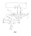
- a passageway 66 is arranged in the core nacelle 60 to provide an air flow from the bypass flow path through the passageway.
- a heat exchanger 64 is arranged in the passageway 66, as best shown in Figure 2 .
- the heat exchanger 64 is in fluid communication with an engine oil loop 91 that includes oil lines 69, 70.
- a coolant loop 92 is also in fluid communication with the heat exchanger and includes coolant lines 71, 72.
- the coolant lines 72 extend from the heat exchanger 64 through a bifurcation 68 arranged in the bypass flow path and interconnecting the core nacelle 60 to the fan nacelle 62.
- the passageway 66 provides an inlet 74 and an exit 76. Air flow through the passageway 66 may be selectively regulated by a door 78 that opens and closes in response to an actuator 80.
- a controller 82 communicates with the actuator 80 to command a position of the door 78 in response to inputs, such as a manual input 84 from a pilot or an automatic input 86 based upon an icing algorithm, for example.
- the controller 82 communicates with various sensors 88, 90, such as temperature and pressure sensors, which can be used to predict an icing condition and desired heat transfer characteristics of the heat exchanger based upon engine operation.
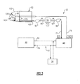
- the engine oil loop 91 circulates lubrication oil from the geared architecture 48 and/or the bearings 38 to the heat exchanger 64 for cooling.
- the coolant loop 92 circulates a coolant to a manifold, such as an annular spray bar 98, arranged in a cavity of the D-duct 102 of the fan nacelle 92.
- the coolant is a phase change fluid, for example, that changes phase from a liquid to a gas or saturated vapor in an operating range of the engine oil, such as a range of 200°F-500°F (93°C-260°C).
- phase change fluid is ammonia 2, 3, 3, 3-tetrafluoropropene, 2, 2-dichloro-1, 1, 1-trifluoroethane, although it should be understood that other phase change fluids may also be used.
- a fluid reservoir 96 and first and second pumps 93, 94 are arranged in the coolant loop 92.
- First and second valves 95, 97 are provided respectively between the first and second pumps 93, 94 and the reservoir 96.
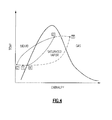
- the coolant at location 1 is a liquid.
- the liquid coolant is pumped from the reservoir 96 with second pump 94 to the heat exchanger 64 to location 2 where heat is transferred from the engine oil to the coolant.
- the enthalpy of the liquid coolant is increased by the engine oil and circulated to the annular spray bar 98.
- the hot gaseous coolant is sprayed through holes 100 in the annular spray bar 98 as a saturated vapor 3 or a gas 3' onto an inner surface of the D-duct 102.
- Ice on an exterior surface 104 of the D-duct 102 is melted as heat is transferred from the hot gaseous coolant or saturated vapor to the ice, which reduces the temperature of the gaseous coolant and condenses the coolant to a liquid at location 4.
- the condensed liquid coolant flows from a drain 106 in the D-duct 102 back to the reservoir 96.
- a level sensor 108 communicates with the controller 82, which operates the first pump 93, which is used to maintain a desired condensate level within the reservoir 96.
- the first and second valves 95, 97 which are in communication with the controller 82, are operated to provide desired flow rates and volumes at various locations throughout the coolant loop 92.
Landscapes
- Engineering & Computer Science (AREA)
- Chemical & Material Sciences (AREA)
- Combustion & Propulsion (AREA)
- Mechanical Engineering (AREA)
- General Engineering & Computer Science (AREA)
- Aviation & Aerospace Engineering (AREA)
- Structures Of Non-Positive Displacement Pumps (AREA)
Applications Claiming Priority (1)
| Application Number | Priority Date | Filing Date | Title |
|---|---|---|---|
| US201462089016P | 2014-12-08 | 2014-12-08 |
Publications (2)
| Publication Number | Publication Date |
|---|---|
| EP3032045A1 true EP3032045A1 (fr) | 2016-06-15 |
| EP3032045B1 EP3032045B1 (fr) | 2018-10-03 |
Family
ID=54782543
Family Applications (1)
| Application Number | Title | Priority Date | Filing Date |
|---|---|---|---|
| EP15197690.9A Active EP3032045B1 (fr) | 2014-12-08 | 2015-12-03 | Système antigivrage de nacelle de moteur à turbine à gaz |
Country Status (2)
| Country | Link |
|---|---|
| US (1) | US20160160758A1 (fr) |
| EP (1) | EP3032045B1 (fr) |
Cited By (1)
| Publication number | Priority date | Publication date | Assignee | Title |
|---|---|---|---|---|
| CN109665107A (zh) * | 2018-12-05 | 2019-04-23 | 中国航空工业集团公司成都飞机设计研究所 | 一种基于发动机热滑油的机翼前缘防冰结构 |
Families Citing this family (16)
| Publication number | Priority date | Publication date | Assignee | Title |
|---|---|---|---|---|
| FR3007738B1 (fr) * | 2013-06-28 | 2015-07-31 | Aircelle Sa | Dispositif de degivrage et de conditionnement pour aeronef |
| FR3027624B1 (fr) * | 2014-10-27 | 2019-04-19 | Safran Aircraft Engines | Circuit de degivrage d'une levre d'entree d'air d'un ensemble propulsif d'aeronef |
| EP3018304B1 (fr) * | 2014-11-06 | 2020-10-14 | United Technologies Corporation | Système de gestion thermique pour moteur à turbine à gaz |
| KR102285456B1 (ko) | 2015-02-10 | 2021-08-03 | 동우 화인켐 주식회사 | 도전패턴 |
| CN110121463B (zh) * | 2016-06-30 | 2022-12-20 | 庞巴迪公司 | 用于在飞机上调节发动机加热的空气的组件和方法 |
| WO2018236449A1 (fr) * | 2017-06-23 | 2018-12-27 | EnisEnerGen, LLC | Système de turbine à gaz |
| US11130582B2 (en) * | 2018-08-03 | 2021-09-28 | Rolls-Royce Corporation | Systems and methods of optimizing cooling and providing useful heating from single phase and two phase heat management in propulsion systems |
| FR3088961A1 (fr) * | 2018-11-22 | 2020-05-29 | Airbus Operations (S.A.S.) | Turbomachine équipée d’un système de dégivrage de l’entrée d’air. |
| FR3093530B1 (fr) * | 2019-03-08 | 2021-04-02 | Safran Aircraft Engines | Turbomachine comportant un échangeur de chaleur formé dans une plateforme |
| US11365647B2 (en) * | 2020-02-28 | 2022-06-21 | Raytheon Technologies Corporation | Closed loop fan inlet vane anti icing system |
| FR3129661A1 (fr) * | 2021-11-29 | 2023-06-02 | Airbus | Systeme de chauffage de dihydrogene et de refroidissement de fluide combines pour aeronef, et aeronef comprenant un tel systeme |
| US20230212956A1 (en) * | 2022-01-03 | 2023-07-06 | Honeywell International Inc. | System and method to increase the temperature of oil used to anti-ice a gas turbine propulsion engine |
| US11834992B2 (en) | 2022-04-27 | 2023-12-05 | General Electric Company | Heat exchanger capacity for one or more heat exchangers associated with an accessory gearbox of a turbofan engine |
| US11680530B1 (en) | 2022-04-27 | 2023-06-20 | General Electric Company | Heat exchanger capacity for one or more heat exchangers associated with a power gearbox of a turbofan engine |
| US12060829B2 (en) | 2022-04-27 | 2024-08-13 | General Electric Company | Heat exchanger capacity for one or more heat exchangers associated with an accessory gearbox of a turbofan engine |
| US12366204B2 (en) | 2022-04-27 | 2025-07-22 | General Electric Company | Heat exchanger capacity for one or more heat exchangers associated with a power gearbox of a turbofan engine |
Citations (4)
| Publication number | Priority date | Publication date | Assignee | Title |
|---|---|---|---|---|
| GB2204361A (en) * | 1987-05-07 | 1988-11-09 | Rolls Royce Plc | Deicing of a geared gas turbine engine |
| US20140205446A1 (en) * | 2013-01-22 | 2014-07-24 | Snecma | Regulated oil cooling system for a turbine engine with deicing of the nacelle |
| WO2014134040A1 (fr) * | 2013-02-28 | 2014-09-04 | United Technologies Corporation | Gestion thermique intégrée avec régulation de flux laminaire de nacelle pour moteur à turbines à gaz à architecture à réducteur |
| WO2014155009A1 (fr) * | 2013-03-26 | 2014-10-02 | Aircelle | Dispositif de refroidissement pour un turbomoteur d'une nacelle d'aéronef |
Family Cites Families (7)
| Publication number | Priority date | Publication date | Assignee | Title |
|---|---|---|---|---|
| US2081963A (en) * | 1935-09-26 | 1937-06-01 | Theodorsen Theodore | Vapor heating system |
| FR2987602B1 (fr) * | 2012-03-02 | 2014-02-28 | Aircelle Sa | Nacelle de turbomoteur equipe d'un echangeur de chaleur |
| US9816897B2 (en) * | 2012-06-06 | 2017-11-14 | Harris Corporation | Wireless engine monitoring system and associated engine wireless sensor network |
| US9429072B2 (en) * | 2013-05-22 | 2016-08-30 | General Electric Company | Return fluid air cooler system for turbine cooling with optional power extraction |
| US9777698B2 (en) * | 2013-11-12 | 2017-10-03 | Daniel Keith Schlak | Multiple motor gas turbine engine system with auxiliary gas utilization |
| US9656756B2 (en) * | 2014-03-10 | 2017-05-23 | The Boeing Company | Turbo-compressor system and method for extracting energy from an aircraft engine |
| US10100748B2 (en) * | 2014-09-15 | 2018-10-16 | The Boeing Company | Dual fuel gas turbine thrust and power control |
-
2015
- 2015-11-20 US US14/947,174 patent/US20160160758A1/en not_active Abandoned
- 2015-12-03 EP EP15197690.9A patent/EP3032045B1/fr active Active
Patent Citations (4)
| Publication number | Priority date | Publication date | Assignee | Title |
|---|---|---|---|---|
| GB2204361A (en) * | 1987-05-07 | 1988-11-09 | Rolls Royce Plc | Deicing of a geared gas turbine engine |
| US20140205446A1 (en) * | 2013-01-22 | 2014-07-24 | Snecma | Regulated oil cooling system for a turbine engine with deicing of the nacelle |
| WO2014134040A1 (fr) * | 2013-02-28 | 2014-09-04 | United Technologies Corporation | Gestion thermique intégrée avec régulation de flux laminaire de nacelle pour moteur à turbines à gaz à architecture à réducteur |
| WO2014155009A1 (fr) * | 2013-03-26 | 2014-10-02 | Aircelle | Dispositif de refroidissement pour un turbomoteur d'une nacelle d'aéronef |
Cited By (1)
| Publication number | Priority date | Publication date | Assignee | Title |
|---|---|---|---|---|
| CN109665107A (zh) * | 2018-12-05 | 2019-04-23 | 中国航空工业集团公司成都飞机设计研究所 | 一种基于发动机热滑油的机翼前缘防冰结构 |
Also Published As
| Publication number | Publication date |
|---|---|
| EP3032045B1 (fr) | 2018-10-03 |
| US20160160758A1 (en) | 2016-06-09 |
Similar Documents
| Publication | Publication Date | Title |
|---|---|---|
| EP3032045B1 (fr) | Système antigivrage de nacelle de moteur à turbine à gaz | |
| EP3872324B1 (fr) | Système anti-givrage d'aube d'entrée de ventilateur en boucle fermée | |
| US11781484B2 (en) | Secondary fuel flow demand fuel pumping system | |
| US11549728B2 (en) | Gas turbine engine with transcritical vapor cycle cooling | |
| EP2809915B1 (fr) | Moteur à turbine à gaz comportant un turboréacteur à double flux à engrenage et un système de gestion thermique d'huile | |
| US10400671B2 (en) | Gas turbine engine thermal management system | |
| EP2981697B1 (fr) | Système d'augmentation de l'écoulement d'air de refroidisseur d'huile par air et procédé correspondant | |
| EP2809907B1 (fr) | Système tampon pour une turbine à gaz | |
| EP3018304A1 (fr) | Système de gestion thermique pour moteur à turbine à gaz | |
| EP3109434B1 (fr) | Échangeur de chaleur avec un conduit de dérivation de ventilateur commandé | |
| US20130284398A1 (en) | Gas turbine engine thermal management system | |
| EP3584427B1 (fr) | Système à air de refroidissement refroidi avec de l'air à basse température pour compartiment de palier | |
| EP2949883B1 (fr) | Système de lubrification de moteur de turbine à gaz | |
| EP3287620B1 (fr) | Compresseur pour circuit de refroidissement de moteur | |
| EP4144971B1 (fr) | Air de refroidissement refroidi avec décharge de pression sélective | |
| EP2971646B1 (fr) | Système de gestion thermique de turbine à gaz |
Legal Events
| Date | Code | Title | Description |
|---|---|---|---|
| PUAI | Public reference made under article 153(3) epc to a published international application that has entered the european phase |
Free format text: ORIGINAL CODE: 0009012 |
|
| AK | Designated contracting states |
Kind code of ref document: A1 Designated state(s): AL AT BE BG CH CY CZ DE DK EE ES FI FR GB GR HR HU IE IS IT LI LT LU LV MC MK MT NL NO PL PT RO RS SE SI SK SM TR |
|
| AX | Request for extension of the european patent |
Extension state: BA ME |
|
| RAP1 | Party data changed (applicant data changed or rights of an application transferred) |
Owner name: UNITED TECHNOLOGIES CORPORATION |
|
| STAA | Information on the status of an ep patent application or granted ep patent |
Free format text: STATUS: REQUEST FOR EXAMINATION WAS MADE |
|
| 17P | Request for examination filed |
Effective date: 20161215 |
|
| RBV | Designated contracting states (corrected) |
Designated state(s): AL AT BE BG CH CY CZ DE DK EE ES FI FR GB GR HR HU IE IS IT LI LT LU LV MC MK MT NL NO PL PT RO RS SE SI SK SM TR |
|
| RIC1 | Information provided on ipc code assigned before grant |
Ipc: F02K 3/06 20060101ALI20180329BHEP Ipc: F02C 7/14 20060101ALI20180329BHEP Ipc: F02C 7/047 20060101ALI20180329BHEP Ipc: F01D 25/02 20060101AFI20180329BHEP Ipc: B64D 33/02 20060101ALI20180329BHEP |
|
| GRAP | Despatch of communication of intention to grant a patent |
Free format text: ORIGINAL CODE: EPIDOSNIGR1 |
|
| STAA | Information on the status of an ep patent application or granted ep patent |
Free format text: STATUS: GRANT OF PATENT IS INTENDED |
|
| INTG | Intention to grant announced |
Effective date: 20180507 |
|
| GRAS | Grant fee paid |
Free format text: ORIGINAL CODE: EPIDOSNIGR3 |
|
| GRAA | (expected) grant |
Free format text: ORIGINAL CODE: 0009210 |
|
| STAA | Information on the status of an ep patent application or granted ep patent |
Free format text: STATUS: THE PATENT HAS BEEN GRANTED |
|
| AK | Designated contracting states |
Kind code of ref document: B1 Designated state(s): AL AT BE BG CH CY CZ DE DK EE ES FI FR GB GR HR HU IE IS IT LI LT LU LV MC MK MT NL NO PL PT RO RS SE SI SK SM TR |
|
| REG | Reference to a national code |
Ref country code: GB Ref legal event code: FG4D |
|
| REG | Reference to a national code |
Ref country code: CH Ref legal event code: EP Ref country code: AT Ref legal event code: REF Ref document number: 1048824 Country of ref document: AT Kind code of ref document: T Effective date: 20181015 |
|
| REG | Reference to a national code |
Ref country code: IE Ref legal event code: FG4D Ref country code: DE Ref legal event code: R096 Ref document number: 602015017420 Country of ref document: DE |
|
| REG | Reference to a national code |
Ref country code: NL Ref legal event code: MP Effective date: 20181003 |
|
| REG | Reference to a national code |
Ref country code: LT Ref legal event code: MG4D |
|
| REG | Reference to a national code |
Ref country code: AT Ref legal event code: MK05 Ref document number: 1048824 Country of ref document: AT Kind code of ref document: T Effective date: 20181003 |
|
| PG25 | Lapsed in a contracting state [announced via postgrant information from national office to epo] |
Ref country code: NL Free format text: LAPSE BECAUSE OF FAILURE TO SUBMIT A TRANSLATION OF THE DESCRIPTION OR TO PAY THE FEE WITHIN THE PRESCRIBED TIME-LIMIT Effective date: 20181003 |
|
| PG25 | Lapsed in a contracting state [announced via postgrant information from national office to epo] |
Ref country code: IS Free format text: LAPSE BECAUSE OF FAILURE TO SUBMIT A TRANSLATION OF THE DESCRIPTION OR TO PAY THE FEE WITHIN THE PRESCRIBED TIME-LIMIT Effective date: 20190203 Ref country code: BG Free format text: LAPSE BECAUSE OF FAILURE TO SUBMIT A TRANSLATION OF THE DESCRIPTION OR TO PAY THE FEE WITHIN THE PRESCRIBED TIME-LIMIT Effective date: 20190103 Ref country code: LT Free format text: LAPSE BECAUSE OF FAILURE TO SUBMIT A TRANSLATION OF THE DESCRIPTION OR TO PAY THE FEE WITHIN THE PRESCRIBED TIME-LIMIT Effective date: 20181003 Ref country code: FI Free format text: LAPSE BECAUSE OF FAILURE TO SUBMIT A TRANSLATION OF THE DESCRIPTION OR TO PAY THE FEE WITHIN THE PRESCRIBED TIME-LIMIT Effective date: 20181003 Ref country code: HR Free format text: LAPSE BECAUSE OF FAILURE TO SUBMIT A TRANSLATION OF THE DESCRIPTION OR TO PAY THE FEE WITHIN THE PRESCRIBED TIME-LIMIT Effective date: 20181003 Ref country code: PL Free format text: LAPSE BECAUSE OF FAILURE TO SUBMIT A TRANSLATION OF THE DESCRIPTION OR TO PAY THE FEE WITHIN THE PRESCRIBED TIME-LIMIT Effective date: 20181003 Ref country code: LV Free format text: LAPSE BECAUSE OF FAILURE TO SUBMIT A TRANSLATION OF THE DESCRIPTION OR TO PAY THE FEE WITHIN THE PRESCRIBED TIME-LIMIT Effective date: 20181003 Ref country code: ES Free format text: LAPSE BECAUSE OF FAILURE TO SUBMIT A TRANSLATION OF THE DESCRIPTION OR TO PAY THE FEE WITHIN THE PRESCRIBED TIME-LIMIT Effective date: 20181003 Ref country code: CZ Free format text: LAPSE BECAUSE OF FAILURE TO SUBMIT A TRANSLATION OF THE DESCRIPTION OR TO PAY THE FEE WITHIN THE PRESCRIBED TIME-LIMIT Effective date: 20181003 Ref country code: NO Free format text: LAPSE BECAUSE OF FAILURE TO SUBMIT A TRANSLATION OF THE DESCRIPTION OR TO PAY THE FEE WITHIN THE PRESCRIBED TIME-LIMIT Effective date: 20190103 Ref country code: AT Free format text: LAPSE BECAUSE OF FAILURE TO SUBMIT A TRANSLATION OF THE DESCRIPTION OR TO PAY THE FEE WITHIN THE PRESCRIBED TIME-LIMIT Effective date: 20181003 |
|
| PG25 | Lapsed in a contracting state [announced via postgrant information from national office to epo] |
Ref country code: PT Free format text: LAPSE BECAUSE OF FAILURE TO SUBMIT A TRANSLATION OF THE DESCRIPTION OR TO PAY THE FEE WITHIN THE PRESCRIBED TIME-LIMIT Effective date: 20190203 Ref country code: GR Free format text: LAPSE BECAUSE OF FAILURE TO SUBMIT A TRANSLATION OF THE DESCRIPTION OR TO PAY THE FEE WITHIN THE PRESCRIBED TIME-LIMIT Effective date: 20190104 Ref country code: RS Free format text: LAPSE BECAUSE OF FAILURE TO SUBMIT A TRANSLATION OF THE DESCRIPTION OR TO PAY THE FEE WITHIN THE PRESCRIBED TIME-LIMIT Effective date: 20181003 Ref country code: SE Free format text: LAPSE BECAUSE OF FAILURE TO SUBMIT A TRANSLATION OF THE DESCRIPTION OR TO PAY THE FEE WITHIN THE PRESCRIBED TIME-LIMIT Effective date: 20181003 Ref country code: AL Free format text: LAPSE BECAUSE OF FAILURE TO SUBMIT A TRANSLATION OF THE DESCRIPTION OR TO PAY THE FEE WITHIN THE PRESCRIBED TIME-LIMIT Effective date: 20181003 |
|
| REG | Reference to a national code |
Ref country code: DE Ref legal event code: R097 Ref document number: 602015017420 Country of ref document: DE |
|
| PG25 | Lapsed in a contracting state [announced via postgrant information from national office to epo] |
Ref country code: IT Free format text: LAPSE BECAUSE OF FAILURE TO SUBMIT A TRANSLATION OF THE DESCRIPTION OR TO PAY THE FEE WITHIN THE PRESCRIBED TIME-LIMIT Effective date: 20181003 Ref country code: DK Free format text: LAPSE BECAUSE OF FAILURE TO SUBMIT A TRANSLATION OF THE DESCRIPTION OR TO PAY THE FEE WITHIN THE PRESCRIBED TIME-LIMIT Effective date: 20181003 |
|
| REG | Reference to a national code |
Ref country code: CH Ref legal event code: PL |
|
| PLBE | No opposition filed within time limit |
Free format text: ORIGINAL CODE: 0009261 |
|
| STAA | Information on the status of an ep patent application or granted ep patent |
Free format text: STATUS: NO OPPOSITION FILED WITHIN TIME LIMIT |
|
| PG25 | Lapsed in a contracting state [announced via postgrant information from national office to epo] |
Ref country code: LU Free format text: LAPSE BECAUSE OF NON-PAYMENT OF DUE FEES Effective date: 20181203 Ref country code: MC Free format text: LAPSE BECAUSE OF FAILURE TO SUBMIT A TRANSLATION OF THE DESCRIPTION OR TO PAY THE FEE WITHIN THE PRESCRIBED TIME-LIMIT Effective date: 20181003 Ref country code: SK Free format text: LAPSE BECAUSE OF FAILURE TO SUBMIT A TRANSLATION OF THE DESCRIPTION OR TO PAY THE FEE WITHIN THE PRESCRIBED TIME-LIMIT Effective date: 20181003 Ref country code: RO Free format text: LAPSE BECAUSE OF FAILURE TO SUBMIT A TRANSLATION OF THE DESCRIPTION OR TO PAY THE FEE WITHIN THE PRESCRIBED TIME-LIMIT Effective date: 20181003 Ref country code: SM Free format text: LAPSE BECAUSE OF FAILURE TO SUBMIT A TRANSLATION OF THE DESCRIPTION OR TO PAY THE FEE WITHIN THE PRESCRIBED TIME-LIMIT Effective date: 20181003 Ref country code: EE Free format text: LAPSE BECAUSE OF FAILURE TO SUBMIT A TRANSLATION OF THE DESCRIPTION OR TO PAY THE FEE WITHIN THE PRESCRIBED TIME-LIMIT Effective date: 20181003 |
|
| 26N | No opposition filed |
Effective date: 20190704 |
|
| REG | Reference to a national code |
Ref country code: IE Ref legal event code: MM4A |
|
| REG | Reference to a national code |
Ref country code: BE Ref legal event code: MM Effective date: 20181231 |
|
| PG25 | Lapsed in a contracting state [announced via postgrant information from national office to epo] |
Ref country code: IE Free format text: LAPSE BECAUSE OF NON-PAYMENT OF DUE FEES Effective date: 20181203 Ref country code: SI Free format text: LAPSE BECAUSE OF FAILURE TO SUBMIT A TRANSLATION OF THE DESCRIPTION OR TO PAY THE FEE WITHIN THE PRESCRIBED TIME-LIMIT Effective date: 20181003 |
|
| PG25 | Lapsed in a contracting state [announced via postgrant information from national office to epo] |
Ref country code: BE Free format text: LAPSE BECAUSE OF NON-PAYMENT OF DUE FEES Effective date: 20181231 |
|
| PG25 | Lapsed in a contracting state [announced via postgrant information from national office to epo] |
Ref country code: CH Free format text: LAPSE BECAUSE OF NON-PAYMENT OF DUE FEES Effective date: 20181231 Ref country code: LI Free format text: LAPSE BECAUSE OF NON-PAYMENT OF DUE FEES Effective date: 20181231 |
|
| PG25 | Lapsed in a contracting state [announced via postgrant information from national office to epo] |
Ref country code: MT Free format text: LAPSE BECAUSE OF NON-PAYMENT OF DUE FEES Effective date: 20181203 |
|
| PG25 | Lapsed in a contracting state [announced via postgrant information from national office to epo] |
Ref country code: TR Free format text: LAPSE BECAUSE OF FAILURE TO SUBMIT A TRANSLATION OF THE DESCRIPTION OR TO PAY THE FEE WITHIN THE PRESCRIBED TIME-LIMIT Effective date: 20181003 |
|
| PG25 | Lapsed in a contracting state [announced via postgrant information from national office to epo] |
Ref country code: HU Free format text: LAPSE BECAUSE OF FAILURE TO SUBMIT A TRANSLATION OF THE DESCRIPTION OR TO PAY THE FEE WITHIN THE PRESCRIBED TIME-LIMIT; INVALID AB INITIO Effective date: 20151203 Ref country code: CY Free format text: LAPSE BECAUSE OF FAILURE TO SUBMIT A TRANSLATION OF THE DESCRIPTION OR TO PAY THE FEE WITHIN THE PRESCRIBED TIME-LIMIT Effective date: 20181003 Ref country code: MK Free format text: LAPSE BECAUSE OF NON-PAYMENT OF DUE FEES Effective date: 20181003 |
|
| REG | Reference to a national code |
Ref country code: DE Ref legal event code: R081 Ref document number: 602015017420 Country of ref document: DE Owner name: RAYTHEON TECHNOLOGIES CORPORATION (N.D.GES.D.S, US Free format text: FORMER OWNER: UNITED TECHNOLOGIES CORPORATION, FARMINGTON, CONN., US Ref country code: DE Ref legal event code: R081 Ref document number: 602015017420 Country of ref document: DE Owner name: RTX CORPORATION (N.D.GES.D. STAATES DELAWARE),, US Free format text: FORMER OWNER: UNITED TECHNOLOGIES CORPORATION, FARMINGTON, CONN., US |
|
| P01 | Opt-out of the competence of the unified patent court (upc) registered |
Effective date: 20230520 |
|
| REG | Reference to a national code |
Ref country code: DE Ref legal event code: R081 Ref document number: 602015017420 Country of ref document: DE Owner name: RTX CORPORATION (N.D.GES.D. STAATES DELAWARE),, US Free format text: FORMER OWNER: RAYTHEON TECHNOLOGIES CORPORATION (N.D.GES.D.STAATES DELAWARE), ARLINGTON, VA, US |
|
| PGFP | Annual fee paid to national office [announced via postgrant information from national office to epo] |
Ref country code: DE Payment date: 20251126 Year of fee payment: 11 |
|
| PGFP | Annual fee paid to national office [announced via postgrant information from national office to epo] |
Ref country code: GB Payment date: 20251119 Year of fee payment: 11 |
|
| PGFP | Annual fee paid to national office [announced via postgrant information from national office to epo] |
Ref country code: FR Payment date: 20251120 Year of fee payment: 11 |