EP3032082A1 - Motorkolben - Google Patents
Motorkolben Download PDFInfo
- Publication number
- EP3032082A1 EP3032082A1 EP15003328.0A EP15003328A EP3032082A1 EP 3032082 A1 EP3032082 A1 EP 3032082A1 EP 15003328 A EP15003328 A EP 15003328A EP 3032082 A1 EP3032082 A1 EP 3032082A1
- Authority
- EP
- European Patent Office
- Prior art keywords
- piston
- bowl
- bore
- along
- rim
- Prior art date
- Legal status (The legal status is an assumption and is not a legal conclusion. Google has not performed a legal analysis and makes no representation as to the accuracy of the status listed.)
- Withdrawn
Links
- 241000782128 Albizia adianthifolia Species 0.000 claims abstract description 8
- 238000002485 combustion reaction Methods 0.000 claims description 17
- 230000006835 compression Effects 0.000 claims description 5
- 238000007906 compression Methods 0.000 claims description 5
- 230000000994 depressogenic effect Effects 0.000 claims 1
- 239000000446 fuel Substances 0.000 description 18
- 238000013461 design Methods 0.000 description 7
- 239000000463 material Substances 0.000 description 7
- 230000007704 transition Effects 0.000 description 5
- 230000008901 benefit Effects 0.000 description 3
- 238000002347 injection Methods 0.000 description 3
- 239000007924 injection Substances 0.000 description 3
- 239000000203 mixture Substances 0.000 description 3
- 230000002301 combined effect Effects 0.000 description 2
- 230000003247 decreasing effect Effects 0.000 description 2
- 238000003754 machining Methods 0.000 description 2
- 239000002184 metal Substances 0.000 description 2
- 238000000034 method Methods 0.000 description 2
- 230000002093 peripheral effect Effects 0.000 description 2
- 230000000717 retained effect Effects 0.000 description 2
- 238000007789 sealing Methods 0.000 description 2
- 238000004904 shortening Methods 0.000 description 2
- 238000012360 testing method Methods 0.000 description 2
- 238000012546 transfer Methods 0.000 description 2
- 238000000889 atomisation Methods 0.000 description 1
- 238000005266 casting Methods 0.000 description 1
- 238000000576 coating method Methods 0.000 description 1
- 238000005474 detonation Methods 0.000 description 1
- 239000012530 fluid Substances 0.000 description 1
- 230000006870 function Effects 0.000 description 1
- 230000005484 gravity Effects 0.000 description 1
- 238000005461 lubrication Methods 0.000 description 1
- 238000004519 manufacturing process Methods 0.000 description 1
- 238000002156 mixing Methods 0.000 description 1
- 238000012986 modification Methods 0.000 description 1
- 230000004048 modification Effects 0.000 description 1
- 230000009467 reduction Effects 0.000 description 1
- 230000029058 respiratory gaseous exchange Effects 0.000 description 1
- 238000009736 wetting Methods 0.000 description 1
Images


Classifications
-
- F—MECHANICAL ENGINEERING; LIGHTING; HEATING; WEAPONS; BLASTING
- F02—COMBUSTION ENGINES; HOT-GAS OR COMBUSTION-PRODUCT ENGINE PLANTS
- F02F—CYLINDERS, PISTONS OR CASINGS, FOR COMBUSTION ENGINES; ARRANGEMENTS OF SEALINGS IN COMBUSTION ENGINES
- F02F3/00—Pistons
- F02F3/28—Other pistons with specially-shaped head
-
- F—MECHANICAL ENGINEERING; LIGHTING; HEATING; WEAPONS; BLASTING
- F02—COMBUSTION ENGINES; HOT-GAS OR COMBUSTION-PRODUCT ENGINE PLANTS
- F02F—CYLINDERS, PISTONS OR CASINGS, FOR COMBUSTION ENGINES; ARRANGEMENTS OF SEALINGS IN COMBUSTION ENGINES
- F02F3/00—Pistons
Definitions
- This disclosure relates generally to internal combustion engines and, more particularly, to pistons operating within engine bores.
- Internal combustion engines typically include one or more pistons interconnected by connecting rods to a crankshaft.
- the pistons are typically disposed to reciprocate within bores formed in a crankcase.
- a typical piston includes a head portion, which at least partially defines a combustion chamber within each bore, and a skirt, which typically includes a pin opening and other support structures for connection to the connecting rod of the engine.
- a piston is formed to have a generally cupped shape, with the piston head forming the base, and the skirt portion being connected to the base and surrounding an enclosed gallery of the piston.
- lubrication oil from the engine is provided within the gallery of the piston during operation to convectively cool and lubricate various portions of the piston.
- a typical piston head also includes an outer cylindrical wall having one or more circumferentially continuous grooves formed therein. These grooves typically extend parallel to one another and are appropriately sized to accommodate sealing rings therewithin. These sealing rings create sliding seals between each piston and the crankcase bore it is operating within.
- the groove located closest to the skirt of the piston accommodates a scrapper ring, which is arranged to scrape oil clinging on the walls of the piston bore during a down-stroke of the piston. Oil that may remain wetting the walls of the bore following the down-stroke of the piston may enter the combustion chamber and combust during operation of the engine.
- the piston operates by reciprocating within a bore formed in a cylinder case of the engine, which creates a variable volume that can compress a fuel/air mixture provided therein.
- the combusting fuel/air mixture expands and pushes the piston to increase the variable volume, thus producing power.
- Fuel can be provided directly or indirectly within the variable volume, while air and exhaust gas is provided or removed from the variable volume through one or more intake and exhaust valves that selectively fluidly connect the variable volume with intake and exhaust collectors.
- the materials used to construct the walls of the engine cylinders, the piston, the various valves associated with the variable volume, and other surrounding engine structures, are selected to withstand high temperatures and pressures that are present during engine operation.
- Various features of the piston are also shaped to promote the efficient burning of fuel within the piston, reliability of the various engine components associated with the engine cylinders, and other considerations. However, it is always desired to increase the reliability and service life of these and other engine components, as well as promote the efficient operation of the engine in terms of reducing fuel consumption and emissions and increasing power and efficiency.
- the disclosure describes a piston for an internal combustion engine.
- the piston includes a piston body forming a crown portion and a skirt portion.
- the skirt portion includes a pin bore that is arranged to receive a pin for connecting the piston to a connecting rod.
- the crown portion forms a bowl surrounded by a flat crown surface having an annular shape and disposed along a plane.
- the bowl and the flat crown surface meet along a rim of the bowl having a generally circular shape.
- a generally cylindrical surface surrounds the crown portion.
- the generally cylindrical surface forms at least two grooves therein that extend parallel to one another.
- the at least two grooves define a top land surface, a bottom land surface, and at least one intermediate land surface along the generally cylindrical surface.
- the top land surface has a height along a centerline of the piston, and the piston has a nominal diameter configured to allow the piston to reciprocally operate within bore having an inner diameter, such that a ratio between the height of the top land surface and the inner diameter of the bore is between 3% and 4.5%.
- This disclosure relates to pistons for use in internal combustion engines.
- the disclosure provides various embodiments for engine pistons having features that can set up flow fields and turbulence to promote combustion of fuel within the cylinder.
- Such features of the piston depending on the type of engine operation, for example, spark ignition or compression ignition, can operate to contain, mix and/or direct various fuel containing masses within the piston to increase engine efficiency, decrease heat rejection, shorten burn time, and also control component temperatures, thus increasing component reliability and service life.
- the mixing or directing of material within the cylinder may occur at least for an instant and may last no more than a few thousandths of a second while an injection of fuel and/or a combustion flame is present within the cylinder, or over portions of that period.
- FIG. 1 For purpose of illustration of certain features of an engine piston in accordance with the disclosure, a fragmented view of a piston 100 for an engine is shown from a side perspective in FIG. 1 , and an outline view thereof from a bottom perspective is shown in FIG. 2 .
- the piston 100 includes a crown portion 102 and a skirt portion 104.
- the skirt portion 104 forms a pin bore 106 that accommodates a pin (not shown) used to pivotally connect the piston to a connecting rod (not shown), which is connected to an engine crankshaft (not shown) in the known fashion.
- the skirt portion 104 further includes two guide surfaces 105 disposed on diametrically opposite sides of the piston 100. In an alternative embodiment, the guide surfaces may be integrated into a single guide surface extending substantially around the piston.
- the two guide surfaces 105 extend at least along cross sections of the piston that include a piston cross section 103, which is shown in FIG. 1 and which is perpendicular to a centerline, C/L, of the pin bore 106, as shown in FIG. 2 .
- the two guide surfaces 105 may extend over two angular portions of the periphery of the piston, each denoted by ⁇ in FIG. 2 and extending about between 70 and 90 degrees.
- each angle ⁇ is about 77 degrees for a total of about 154 degrees of coverage around the piston 100.
- each of the two guide surfaces 105 extends on an outer portion of the skirt portion 104 over a height, H, in a direction along a centerline, C, of the piston 100.
- the diameter, D, of the pin bore 106 along the centerline C of the piston 100 at least partially overlaps the height, H, of the guide surface such that the skirt portion 104 partially supports the piston 100 during operation by counteracting forces and moments present in the piston between the connecting rod, via the pin disposed in the pin bore 106, and a piston bore into which the piston is disposed.
- the piston to provide full support to the piston, i.e., a full coverage of the pin bore 106, the piston includes a secondary guide surface 108, which is formed as the second land between piston ring grooves 110 formed in the peripheral, outer cylindrical wall 112 of the crown portion 102.
- the crown portion 102 includes piston ring grooves 110 in the outer cylindrical wall 112.
- the piston ring grooves 110 accommodate ring seals (not shown) that slidably and generally sealably engage the walls of the engine cylinder in which the piston 100 is reciprocally disposed.
- An outer diameter of the two guide surfaces 105 and the secondary guide surface 108 is arranged such that the piston is prevented from rotating or binding within the bore in which it is reciprocally disposed during operation.
- the two guide surfaces 105 and secondary guide surface 108 collectively cover a length along the centerline, C, of the piston that entirely includes along the same direction the pin bore 106 such that full coverage is provided.
- the crown portion 102 forms a bowl 114 having generally a concave shape.
- the bowl 114 is surrounded by a rim 116.
- the rim 116 is centrally disposed relative to the centerline, C, and has a generally circular shape.
- An annularly shaped, flat, crown surface 118 is disposed around the rim 116 of the bowl 144.
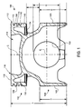
- a detailed, enlarged view of the bowl 114 is shown in FIG. 3 .
- the bowl 114 forms a frusto-conical wall surface 117 adjacent the rim 116.
- the frusto-conical wall surface 117 surrounds the bowl 114 and is formed at an angle, ⁇ , of about 80 degrees with respect to the crown surface 118.
- the convex surface 120 Around the center of the bowl is a convex surface 120 that is centrally disposed with respect to the piston 100.
- the convex surface 120 has a radius, R1, of about 155 mm, but other radii can also be selected. From a functional standpoint, the radius of the convex surface 120 determines the overall volume of the bowl 114, which in turn determines the volume of the combustion chamber when the piston is at the top dead center position within the bore and also the compression ratio of the engine. Thus, the radius R1 of the convex surface 120 can be selected depending on the desired compression ratio of the particular engine in which the piston is installed and will operate.
- a concave surface 122 Surrounding the convex surface 120 and disposed within the frusto-conical wall surface 117 is a concave surface 122.
- the concave surface 122 is formed at a radius of about 10 mm and extends peripherally around the convex surface 120.
- the rim 116 is relatively sharp or formed at a relatively small de-burr chamfer, for example, of about 0.25 mm or less.
- the piston 100 forms various features that operate to redirect and/or contain various moving masses within the cylinder.
- these features operate to split the hot injector fuel plume that is provided to the cylinder when the piston is close to a top dead center position in the cylinder, and also which may be provided while the piston is approaching the top dead center position (e.g., pilot injection events) and/or is moving away from the top dead center position (e.g. post injection events during a combustion stroke).
- the fuel plume, a fuel atomization cloud, and/or a flame of burning fuel during these times of engine operation can be redirected in terms of flow direction and material dissipation in a fashion that reduces exposure of the various surrounding in-cylinder combustion surfaces to flame temperatures.
- the piston 100 achieves flow detachment along the crown surface 118 and material turbulation within the bowl 114 by the combined effects or primarily the frusto-conical wall surface 117 and the rim 116 having a sharp transition. These features operate to keep the burning fuel away from the edges of the piston.
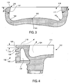
- FIG. 4 An enlarged view of the crown portion 102 is shown in FIG. 4 .
- a cross section showing the edge of the bowl 114 is annotated with dashed-line arrows to show the direction of burning material motion during at least an instant of operation of the piston.
- a moving mass of burning fuel is turbulated or mixed within the bowl 114 in a region that generally follows a path 124.
- Surrounding air from within the combustion chamber is drawn in along a path 126.
- the combined effects of combustion that is, at least partially, provided by the various piston features described, enables a reduction in the height of the crown portion 102, in general, and the top land 128, in specific.
- the top land 128, as described herein, is a portion of the outer cylindrical wall 112 of the piston 100 that is disposed between the uppermost one of the piston ring grooves 110 and the crown surface 118.
- the height of the top land would be increased such that the topmost ring disposed in the topmost one of the piston ring grooves 110 would be further away from the heat generated during fuel burning within the cylinder.
- the height of the top land 128, along with the dead volume it creates around the piston can be reduced.
- the top land has a height, L ( FIG. 4 ), of a nominal dimension of about 6 mm, ⁇ 0.5 mm.
- the piston 100 has a nominal outer diameter (as measured at the skirt) that is consistent with a bore diameter of 170 mm. This means that the ratio between the top land height to the nominal diameter of the piston is about 3.5%, or within a range between 3% and 4.5%.
- annular oil gallery 130 which is formed within the crown portion 102 between the outer cylindrical wall 112 and the bowl 114 (also see FIG. 1 ), helps remove heat generated at the bowl 114 and the crown surface 118 that would tend to migrate via conduction towards the topmost one of the piston ring grooves 110 and the ring disposed therein (not shown).
- FIG. 5 An enlarged detail view of a portion of the piston 100 is shown in FIG. 5 .
- the gallery is open at one end along an opening 132, which is closed during operation by an annularly shaped, generally conical plate 134 ( FIG. 1 ).
- the conical plate 134 is retained between a lower surface 136 and an upper surface 138 disposed on either side of the opening 132.
- various convex and concave surfaces are formed around the cavity volume to generally follow the shape of the external piston features such as the bowl 114, the crown surface 118, and the outer cylindrical wall 112.
- an axial distance, X that is required for tool access when forming the annular oil gallery 130 through the opening 132.
- the axial distance, X at least partially overlaps with an upper end of the diameter D of the pin bores, which is why the two guide surfaces 105 can only partially support the piston and the secondary guide surface 108 must be used to fully support the piston.
- the axial distance, X also tends to increase the overall length, L, of the piston in a direction along the centerline, C, of the piston.
- the increase in overall length L of the piston 100 increases the mass of the piston and also increases the overall rotational moment of the engine crankshaft to which the piston is connected.
- FIG. 6 an alternative design for a piston 200 is shown in FIG. 6 .
- the piston 200 includes various structures and features that are the same or similar to corresponding structures and features of the piston 100 are denoted by the same or similar reference numerals and letters as previously used for discussion, but should not necessarily be understood as limiting the scope of the disclosure to those elements shown.
- the height H' of the two guide surfaces 105 is longer than and completely covers or overlaps with the diameter, D, of the pin bore 106. This means that the skirt portion 104 of the piston 200 completely supports the pin bore 106 and additional support from the outer cylindrical wall 112 of the crown portion 102 is not required. Because no support from the outer cylindrical wall 112 or any of the lands disposed therein is required, the overall height of the outer cylindrical wall 112 can be reduced, as can the distance X' between the outer cylindrical wall 112 and the two guide surfaces 105 can be reduced while still maintaining sufficient tool clearance for machining the annular oil gallery 130.
- the center of gravity of the piston 200 can move closer to the centerline C/L of the pin (not shown) disposed in the pin bore 106, the overall weight of the piston 200 can be reduced, as compared to the piston 100 ( FIG. 1 ), and the rotational moment of inertia of the crankshaft of the engine in which the piston is installed can be reduced.
- the present disclosure is applicable to pistons for internal combustion engines, which can be used in any application such as land or marine based applications, as well as for mobile or stationary applications.
- the various embodiments for piston features described herein have been found to have advantages in improving engine operation by increasing power output, decreasing fuel consumption and also decreasing emissions.
- the heat release rate of a cylinder as a function of crankshaft angle rotation in degrees (CAD), for three piston designs was considered.
- the three piston designs included a baseline piston, in which the bowl includes a peripherally extending wall surface that is shallow or, stated differently, the inclination angle of the baseline piston bowl that corresponds to the angle, ⁇ (see FIG. 3 ), was more than 90 degrees.
- the analysis further included a second, intermediate piston, in which the peripherally extending wall surface of the piston bowl was generally cylindrical or, stated differently, the inclination angle corresponding to the angle, ⁇ , was about 90 degrees.
- a third piston was considered, in which the angle, ⁇ , was about 80 degrees, as shown in the piston 100 illustrated, for example, in FIG. 3 .
- the peak IHRR for the baseline piston was determined to be at about 0.032 (1/CAD)
- the peak IHRR for the second piston was at about 0.037
- the third piston was at about 0.042, which represents an increase of more than 30% in the IHRR for the cylinder over the baseline piston, which was unexpected.
- a peak IHRR as high as 0.055 (1/CAD) was observed, which is about a 72% increase over the baseline piston.
- the test conditions for measuring the reported peak IHRR values were run on a gas, spark-ignited engine operating at 2220 kPa IMEP, generating about 180 ppm NOx, having an intake manifold absolute temperature of about 51 deg.
- IHRR IMAT
- BTDC top dead center
- FIG. 1 Another feature of the piston 100 ( FIG. 1 ) that has been found to affect engine operation, for example, in apparent heat release rate in the cylinder, is the sharpness of the piston bowl rim or edge radius, when the transition is formed as a chamfer, which is denoted by reference numeral 116, for example, in FIG. 1 .
- the apparent heat release rate (AHRR) with respect to crank angle was measured for a baseline piston design, in which a rim radius for a chamfer transition was about 5 mm, an intermediate piston, in which a rim radius was about 2.5 mm, and a third piston, which corresponds to the piston 100 ( FIG. 1 ), in which the rim radius was about 0.25 mm.
- the maximum AHRR for the baseline piston was about 0.84 kJ/CAD
- the maximum AHRR for the intermediate piston was about 0.88 kJ/CAD
- the maximum AHRR for the piston in accordance with the present disclosure was, surprisingly, about 1.06 kJ/CAD, which represents an increase of about 26% over the baseline piston. It is believed that the sharper bowl edge, which exhibits higher combustion efficiency and improved knock or detonation margin in the cylinder, improved engine operation by also shortening the duration of fuel burn within the cylinder.
Landscapes
- Engineering & Computer Science (AREA)
- Chemical & Material Sciences (AREA)
- Combustion & Propulsion (AREA)
- Mechanical Engineering (AREA)
- General Engineering & Computer Science (AREA)
- Pistons, Piston Rings, And Cylinders (AREA)
Applications Claiming Priority (1)
| Application Number | Priority Date | Filing Date | Title |
|---|---|---|---|
| US14/567,144 US20160169152A1 (en) | 2014-12-11 | 2014-12-11 | Engine Piston |
Publications (1)
| Publication Number | Publication Date |
|---|---|
| EP3032082A1 true EP3032082A1 (de) | 2016-06-15 |
Family
ID=54703706
Family Applications (1)
| Application Number | Title | Priority Date | Filing Date |
|---|---|---|---|
| EP15003328.0A Withdrawn EP3032082A1 (de) | 2014-12-11 | 2015-11-23 | Motorkolben |
Country Status (3)
| Country | Link |
|---|---|
| US (1) | US20160169152A1 (de) |
| EP (1) | EP3032082A1 (de) |
| CN (1) | CN105697182A (de) |
Families Citing this family (3)
| Publication number | Priority date | Publication date | Assignee | Title |
|---|---|---|---|---|
| US10400663B2 (en) | 2017-12-18 | 2019-09-03 | Caterpillar Inc. | Piston bowl for improved combustion stability |
| US11047293B1 (en) | 2020-09-28 | 2021-06-29 | Caterpillar Inc. | Engine operating method and piston having non-reentrant combustion bowl and anti-sooting ramp |
| US12146452B1 (en) * | 2023-07-13 | 2024-11-19 | Caterpillar Inc. | Piston and engine system using same |
Citations (10)
| Publication number | Priority date | Publication date | Assignee | Title |
|---|---|---|---|---|
| US4941440A (en) * | 1988-10-21 | 1990-07-17 | Caterpillar Inc. | Engine including a piston member having a high top ring groove |
| US5146883A (en) * | 1990-05-24 | 1992-09-15 | Kolbenschmidt Aktiengesellschaft | Piston and connecting rod assembly |
| US5323744A (en) * | 1992-06-22 | 1994-06-28 | Kabushiki Kaisha Riken | Piston for internal combustion engines |
| DE69116512T2 (de) * | 1990-11-08 | 1996-05-30 | Ford Werke Ag | Aluminium-Gusslegierung |
| WO1997048895A1 (en) * | 1996-06-14 | 1997-12-24 | Metal Leve S.A. Indústria E Comércio | A piston for an internal combustion engine |
| US20030075042A1 (en) * | 2001-10-23 | 2003-04-24 | Federal-Mogul World Wide, Inc. | Monobloc piston |
| US20080148933A1 (en) * | 2006-12-21 | 2008-06-26 | Gm Global Technology Operations, Inc. | Piston top chamfer design to reduce noise and friction |
| US20110253096A1 (en) * | 2010-04-20 | 2011-10-20 | Caterpillar Inc. | Piston having combustion bowl shaped to balance combustion efficiency and emission properties |
| US20130220266A1 (en) * | 2011-08-29 | 2013-08-29 | Deep Bandyopadhyay | Piston |
| DE102013009164A1 (de) * | 2013-05-31 | 2014-12-04 | Mahle International Gmbh | Kolben für einen Verbrennungsmotor |
Family Cites Families (24)
| Publication number | Priority date | Publication date | Assignee | Title |
|---|---|---|---|---|
| DE2253868B2 (de) * | 1972-11-03 | 1980-11-20 | M.A.N. Maschinenfabrik Augsburg-Nuernberg Ag, 8500 Nuernberg | Einteiliger, mit einer Pleuelstange verbundener Gußeisenkolben |
| FR2385904A1 (fr) * | 1977-03-28 | 1978-10-27 | Promeyrat Casteilla Tech Nle M | Piston alternatif a pourtour de tete auto-adaptable pour l'amelioration fondamentale du moteur thermique, et autres machines a pistons alternatifs |
| US4245611A (en) * | 1978-09-05 | 1981-01-20 | General Motors Corporation | Ceramic insulated engine pistons |
| JPS5627047A (en) * | 1979-08-07 | 1981-03-16 | Honda Motor Co Ltd | 4-cycle engine |
| IT1240526B (it) * | 1990-07-31 | 1993-12-17 | Borgo Nova S.P.A. | Perfezionamento relativo a pistoni, in genere. |
| DE19535590A1 (de) * | 1994-09-26 | 1996-04-04 | Unisia Jecs Corp | Kolben für Brennkraftmaschinen und Verfahren zu deren Herstellung |
| GB9605838D0 (en) * | 1996-03-20 | 1996-05-22 | Perkins Ltd | A method for producing a piston for an internal combustion engine and a piston produced by the method |
| US5660156A (en) * | 1996-05-16 | 1997-08-26 | Zollner Corporation | Cast piston having reinforced combustion bowl edge |
| SE510909C2 (sv) * | 1997-01-16 | 1999-07-05 | Volvo Ab | Förbränningmotorkolv |
| GB0007726D0 (en) * | 2000-03-31 | 2000-05-17 | Galvin George F | Piston |
| EP2295777B1 (de) * | 2003-03-31 | 2016-12-07 | Hitachi Metals, Ltd. | Kolben für eine Verbrennungsmaschine und Verfahren zu seiner Herstellung |
| DE102005060547A1 (de) * | 2005-12-17 | 2007-06-28 | Mahle International Gmbh | Kolben für einen Verbrennungsmotor und Verfahren zu seiner Herstellung |
| US7458358B2 (en) * | 2006-05-10 | 2008-12-02 | Federal Mogul World Wide, Inc. | Thermal oxidation protective surface for steel pistons |
| DE102008002572A1 (de) * | 2008-06-20 | 2009-12-24 | Federal-Mogul Nürnberg GmbH | Verfahren zur Herstellung eines Kolbens für einen Verbrennungsmotor sowie Kolben für einen Verbrennungsmotor |
| US20100108044A1 (en) * | 2008-11-06 | 2010-05-06 | International Engine Intellectual Property Company, Llc | Combustion Chamber with Double Convex Surfaces and Double Concave Surfaces |
| US8291881B2 (en) * | 2009-12-22 | 2012-10-23 | Perkins Engine Company Limited | Piston for internal combustion engine |
| US9234451B2 (en) * | 2010-04-20 | 2016-01-12 | Caterpillar Inc. | Piston having combustion bowl shaped to balance combustion efficiency and emission properties |
| US8813713B2 (en) * | 2010-12-22 | 2014-08-26 | Caterpillar Inc. | Piston with cylindrical wall |
| US8671905B2 (en) * | 2011-07-12 | 2014-03-18 | Mahle International Gmbh | Piston for an internal combustion engine and method for its production |
| KR102068372B1 (ko) * | 2012-03-12 | 2020-01-20 | 테네코 인코퍼레이티드 | 엔진 피스톤 |
| DE102012103193B4 (de) * | 2012-04-13 | 2018-05-30 | Caterpillar Energy Solutions Gmbh | Verwendung eines Kolbens für einen Otto-Motor mit externer Gemischbildung und Otto-Motor |
| EP2752564A1 (de) * | 2013-01-08 | 2014-07-09 | Perkins Engines Company Limited | Kolben |
| US9228531B2 (en) * | 2013-05-13 | 2016-01-05 | Caterpillar Inc. | Piston having combustion bowl and engine using same |
| US20160169153A1 (en) * | 2014-12-11 | 2016-06-16 | Caterpillar Inc. | Engine Piston |
-
2014
- 2014-12-11 US US14/567,144 patent/US20160169152A1/en not_active Abandoned
-
2015
- 2015-11-23 EP EP15003328.0A patent/EP3032082A1/de not_active Withdrawn
- 2015-12-10 CN CN201510917635.2A patent/CN105697182A/zh active Pending
Patent Citations (11)
| Publication number | Priority date | Publication date | Assignee | Title |
|---|---|---|---|---|
| US4941440A (en) * | 1988-10-21 | 1990-07-17 | Caterpillar Inc. | Engine including a piston member having a high top ring groove |
| US4941440B1 (en) * | 1988-10-21 | 2000-06-06 | Caterpillar Inc | Engine including a piston member having a high top ring groove |
| US5146883A (en) * | 1990-05-24 | 1992-09-15 | Kolbenschmidt Aktiengesellschaft | Piston and connecting rod assembly |
| DE69116512T2 (de) * | 1990-11-08 | 1996-05-30 | Ford Werke Ag | Aluminium-Gusslegierung |
| US5323744A (en) * | 1992-06-22 | 1994-06-28 | Kabushiki Kaisha Riken | Piston for internal combustion engines |
| WO1997048895A1 (en) * | 1996-06-14 | 1997-12-24 | Metal Leve S.A. Indústria E Comércio | A piston for an internal combustion engine |
| US20030075042A1 (en) * | 2001-10-23 | 2003-04-24 | Federal-Mogul World Wide, Inc. | Monobloc piston |
| US20080148933A1 (en) * | 2006-12-21 | 2008-06-26 | Gm Global Technology Operations, Inc. | Piston top chamfer design to reduce noise and friction |
| US20110253096A1 (en) * | 2010-04-20 | 2011-10-20 | Caterpillar Inc. | Piston having combustion bowl shaped to balance combustion efficiency and emission properties |
| US20130220266A1 (en) * | 2011-08-29 | 2013-08-29 | Deep Bandyopadhyay | Piston |
| DE102013009164A1 (de) * | 2013-05-31 | 2014-12-04 | Mahle International Gmbh | Kolben für einen Verbrennungsmotor |
Also Published As
| Publication number | Publication date |
|---|---|
| US20160169152A1 (en) | 2016-06-16 |
| CN105697182A (zh) | 2016-06-22 |
Similar Documents
| Publication | Publication Date | Title |
|---|---|---|
| EP3032081A1 (de) | Motorkolben | |
| US10184388B1 (en) | Engine piston | |
| EP3023610B1 (de) | Motorkolben | |
| EP2978962B1 (de) | Kolbenwärmeverwaltung in einem motor mit versetzten kolben | |
| EP3032082A1 (de) | Motorkolben | |
| US11053838B2 (en) | Combustion chamber geometry | |
| EP1112442B1 (de) | Hubkolbenmaschine mit zwei hilfskammern | |
| US7131405B2 (en) | Rotating cylinder valve engine | |
| CN107636276B (zh) | 四冲程内燃发动机以及用于该发动机的活塞 | |
| CN205135827U (zh) | 用于内燃机的活塞 | |
| EP0604223A1 (de) | Kolbenskopf fur Dieselmotor | |
| EP3594469B1 (de) | Zweitaktmotor mit unidirektionaler spülung | |
| EP3023612B1 (de) | Motorkolben | |
| EP3023611B1 (de) | Motorkolben | |
| US9822729B2 (en) | Engine piston having a notched top land | |
| JP2019120185A (ja) | シリンダーの周壁面構造 | |
| EP2630354B1 (de) | Verfahren und vorrichtung zur steuerung einer verbrennung | |
| CN110036190A (zh) | 内燃机的活塞 | |
| CN118715361A (zh) | 用于改善燃烧稳定性的低压缩天然气发动机活塞顶凹腔 | |
| US10227949B2 (en) | Piston for an internal combustion engine and method for producing said piston | |
| FI128417B (en) | Cylinder liner with slots |
Legal Events
| Date | Code | Title | Description |
|---|---|---|---|
| PUAI | Public reference made under article 153(3) epc to a published international application that has entered the european phase |
Free format text: ORIGINAL CODE: 0009012 |
|
| AK | Designated contracting states |
Kind code of ref document: A1 Designated state(s): AL AT BE BG CH CY CZ DE DK EE ES FI FR GB GR HR HU IE IS IT LI LT LU LV MC MK MT NL NO PL PT RO RS SE SI SK SM TR |
|
| AX | Request for extension of the european patent |
Extension state: BA ME |
|
| 17P | Request for examination filed |
Effective date: 20161215 |
|
| RBV | Designated contracting states (corrected) |
Designated state(s): AL AT BE BG CH CY CZ DE DK EE ES FI FR GB GR HR HU IE IS IT LI LT LU LV MC MK MT NL NO PL PT RO RS SE SI SK SM TR |
|
| 17Q | First examination report despatched |
Effective date: 20191030 |
|
| STAA | Information on the status of an ep patent application or granted ep patent |
Free format text: STATUS: THE APPLICATION IS DEEMED TO BE WITHDRAWN |
|
| 18D | Application deemed to be withdrawn |
Effective date: 20200820 |