EP3034236A1 - Temperaturmessverfahren und temperaturmessvorrichtung - Google Patents
Temperaturmessverfahren und temperaturmessvorrichtung Download PDFInfo
- Publication number
- EP3034236A1 EP3034236A1 EP14836301.3A EP14836301A EP3034236A1 EP 3034236 A1 EP3034236 A1 EP 3034236A1 EP 14836301 A EP14836301 A EP 14836301A EP 3034236 A1 EP3034236 A1 EP 3034236A1
- Authority
- EP
- European Patent Office
- Prior art keywords
- temperature measurement
- rotating
- tool
- unit
- holder
- Prior art date
- Legal status (The legal status is an assumption and is not a legal conclusion. Google has not performed a legal analysis and makes no representation as to the accuracy of the status listed.)
- Granted
Links
Images




Classifications
-
- B—PERFORMING OPERATIONS; TRANSPORTING
- B23—MACHINE TOOLS; METAL-WORKING NOT OTHERWISE PROVIDED FOR
- B23Q—DETAILS, COMPONENTS, OR ACCESSORIES FOR MACHINE TOOLS, e.g. ARRANGEMENTS FOR COPYING OR CONTROLLING; MACHINE TOOLS IN GENERAL CHARACTERISED BY THE CONSTRUCTION OF PARTICULAR DETAILS OR COMPONENTS; COMBINATIONS OR ASSOCIATIONS OF METAL-WORKING MACHINES, NOT DIRECTED TO A PARTICULAR RESULT
- B23Q17/00—Arrangements for observing, indicating or measuring on machine tools
- B23Q17/09—Arrangements for observing, indicating or measuring on machine tools for indicating or measuring cutting pressure or for determining cutting-tool condition, e.g. cutting ability, load on tool
- B23Q17/0952—Arrangements for observing, indicating or measuring on machine tools for indicating or measuring cutting pressure or for determining cutting-tool condition, e.g. cutting ability, load on tool during machining
-
- G—PHYSICS
- G01—MEASURING; TESTING
- G01K—MEASURING TEMPERATURE; MEASURING QUANTITY OF HEAT; THERMALLY-SENSITIVE ELEMENTS NOT OTHERWISE PROVIDED FOR
- G01K13/00—Thermometers specially adapted for specific purposes
- G01K13/04—Thermometers specially adapted for specific purposes for measuring temperature of moving solid bodies
- G01K13/08—Thermometers specially adapted for specific purposes for measuring temperature of moving solid bodies in rotary movement
-
- B—PERFORMING OPERATIONS; TRANSPORTING
- B23—MACHINE TOOLS; METAL-WORKING NOT OTHERWISE PROVIDED FOR
- B23K—SOLDERING OR UNSOLDERING; WELDING; CLADDING OR PLATING BY SOLDERING OR WELDING; CUTTING BY APPLYING HEAT LOCALLY, e.g. FLAME CUTTING; WORKING BY LASER BEAM
- B23K20/00—Non-electric welding by applying impact or other pressure, with or without the application of heat, e.g. cladding or plating
- B23K20/12—Non-electric welding by applying impact or other pressure, with or without the application of heat, e.g. cladding or plating the heat being generated by friction; Friction welding
- B23K20/122—Non-electric welding by applying impact or other pressure, with or without the application of heat, e.g. cladding or plating the heat being generated by friction; Friction welding using a non-consumable tool, e.g. friction stir welding
- B23K20/1245—Non-electric welding by applying impact or other pressure, with or without the application of heat, e.g. cladding or plating the heat being generated by friction; Friction welding using a non-consumable tool, e.g. friction stir welding characterised by the apparatus
- B23K20/1255—Tools therefor, e.g. characterised by the shape of the probe
-
- B—PERFORMING OPERATIONS; TRANSPORTING
- B23—MACHINE TOOLS; METAL-WORKING NOT OTHERWISE PROVIDED FOR
- B23K—SOLDERING OR UNSOLDERING; WELDING; CLADDING OR PLATING BY SOLDERING OR WELDING; CUTTING BY APPLYING HEAT LOCALLY, e.g. FLAME CUTTING; WORKING BY LASER BEAM
- B23K26/00—Working by laser beam, e.g. welding, cutting or boring
-
- B—PERFORMING OPERATIONS; TRANSPORTING
- B23—MACHINE TOOLS; METAL-WORKING NOT OTHERWISE PROVIDED FOR
- B23K—SOLDERING OR UNSOLDERING; WELDING; CLADDING OR PLATING BY SOLDERING OR WELDING; CUTTING BY APPLYING HEAT LOCALLY, e.g. FLAME CUTTING; WORKING BY LASER BEAM
- B23K26/00—Working by laser beam, e.g. welding, cutting or boring
- B23K26/0093—Working by laser beam, e.g. welding, cutting or boring combined with mechanical machining or metal-working covered by other subclasses than B23K
-
- B—PERFORMING OPERATIONS; TRANSPORTING
- B23—MACHINE TOOLS; METAL-WORKING NOT OTHERWISE PROVIDED FOR
- B23K—SOLDERING OR UNSOLDERING; WELDING; CLADDING OR PLATING BY SOLDERING OR WELDING; CUTTING BY APPLYING HEAT LOCALLY, e.g. FLAME CUTTING; WORKING BY LASER BEAM
- B23K26/00—Working by laser beam, e.g. welding, cutting or boring
- B23K26/02—Positioning or observing the workpiece, e.g. with respect to the point of impact; Aligning, aiming or focusing the laser beam
- B23K26/03—Observing, e.g. monitoring, the workpiece
- B23K26/032—Observing, e.g. monitoring, the workpiece using optical means
-
- B—PERFORMING OPERATIONS; TRANSPORTING
- B23—MACHINE TOOLS; METAL-WORKING NOT OTHERWISE PROVIDED FOR
- B23K—SOLDERING OR UNSOLDERING; WELDING; CLADDING OR PLATING BY SOLDERING OR WELDING; CUTTING BY APPLYING HEAT LOCALLY, e.g. FLAME CUTTING; WORKING BY LASER BEAM
- B23K26/00—Working by laser beam, e.g. welding, cutting or boring
- B23K26/02—Positioning or observing the workpiece, e.g. with respect to the point of impact; Aligning, aiming or focusing the laser beam
- B23K26/03—Observing, e.g. monitoring, the workpiece
- B23K26/034—Observing the temperature of the workpiece
-
- B—PERFORMING OPERATIONS; TRANSPORTING
- B23—MACHINE TOOLS; METAL-WORKING NOT OTHERWISE PROVIDED FOR
- B23K—SOLDERING OR UNSOLDERING; WELDING; CLADDING OR PLATING BY SOLDERING OR WELDING; CUTTING BY APPLYING HEAT LOCALLY, e.g. FLAME CUTTING; WORKING BY LASER BEAM
- B23K26/00—Working by laser beam, e.g. welding, cutting or boring
- B23K26/34—Laser welding for purposes other than joining
- B23K26/342—Build-up welding
-
- B—PERFORMING OPERATIONS; TRANSPORTING
- B23—MACHINE TOOLS; METAL-WORKING NOT OTHERWISE PROVIDED FOR
- B23K—SOLDERING OR UNSOLDERING; WELDING; CLADDING OR PLATING BY SOLDERING OR WELDING; CUTTING BY APPLYING HEAT LOCALLY, e.g. FLAME CUTTING; WORKING BY LASER BEAM
- B23K9/00—Arc welding or cutting
- B23K9/095—Monitoring or automatic control of welding parameters
- B23K9/0956—Monitoring or automatic control of welding parameters using sensing means, e.g. optical
-
- B—PERFORMING OPERATIONS; TRANSPORTING
- B23—MACHINE TOOLS; METAL-WORKING NOT OTHERWISE PROVIDED FOR
- B23Q—DETAILS, COMPONENTS, OR ACCESSORIES FOR MACHINE TOOLS, e.g. ARRANGEMENTS FOR COPYING OR CONTROLLING; MACHINE TOOLS IN GENERAL CHARACTERISED BY THE CONSTRUCTION OF PARTICULAR DETAILS OR COMPONENTS; COMBINATIONS OR ASSOCIATIONS OF METAL-WORKING MACHINES, NOT DIRECTED TO A PARTICULAR RESULT
- B23Q17/00—Arrangements for observing, indicating or measuring on machine tools
- B23Q17/09—Arrangements for observing, indicating or measuring on machine tools for indicating or measuring cutting pressure or for determining cutting-tool condition, e.g. cutting ability, load on tool
- B23Q17/0952—Arrangements for observing, indicating or measuring on machine tools for indicating or measuring cutting pressure or for determining cutting-tool condition, e.g. cutting ability, load on tool during machining
- B23Q17/0985—Arrangements for observing, indicating or measuring on machine tools for indicating or measuring cutting pressure or for determining cutting-tool condition, e.g. cutting ability, load on tool during machining by measuring temperature
-
- B—PERFORMING OPERATIONS; TRANSPORTING
- B23—MACHINE TOOLS; METAL-WORKING NOT OTHERWISE PROVIDED FOR
- B23Q—DETAILS, COMPONENTS, OR ACCESSORIES FOR MACHINE TOOLS, e.g. ARRANGEMENTS FOR COPYING OR CONTROLLING; MACHINE TOOLS IN GENERAL CHARACTERISED BY THE CONSTRUCTION OF PARTICULAR DETAILS OR COMPONENTS; COMBINATIONS OR ASSOCIATIONS OF METAL-WORKING MACHINES, NOT DIRECTED TO A PARTICULAR RESULT
- B23Q5/00—Driving or feeding mechanisms; Control arrangements therefor
- B23Q5/02—Driving main working members
- B23Q5/04—Driving main working members rotary shafts, e.g. working-spindles
-
- G—PHYSICS
- G05—CONTROLLING; REGULATING
- G05B—CONTROL OR REGULATING SYSTEMS IN GENERAL; FUNCTIONAL ELEMENTS OF SUCH SYSTEMS; MONITORING OR TESTING ARRANGEMENTS FOR SUCH SYSTEMS OR ELEMENTS
- G05B19/00—Program-control systems
- G05B19/02—Program-control systems electric
- G05B19/18—Numerical control [NC], i.e. automatically operating machines, in particular machine tools, e.g. in a manufacturing environment, so as to execute positioning, movement or co-ordinated operations by means of program data in numerical form
- G05B19/406—Numerical control [NC], i.e. automatically operating machines, in particular machine tools, e.g. in a manufacturing environment, so as to execute positioning, movement or co-ordinated operations by means of program data in numerical form characterised by monitoring or safety
- G05B19/4065—Monitoring tool breakage, life or condition
Definitions
- the present invention relates to a temperature measurement method and a temperature measurement device for a rotating tool used in processing.
- the present invention relates to, in particular, a temperature measurement method and a temperature measurement device for a cutting tool that cuts a target during cutting, and a temperature measurement method and a temperature measurement device for a rotating tool such as a welding torch.
- the performances of cutting oil used for cutting a target have been conventionally evaluated based on "how much tool wear is suppressed (how long the tool life is)” and "how much the quality of a processed face can be improved (how much a processed face is fairly finished)".
- the performances of the cutting oil have been evaluated by measuring wear of the cutting tool used in an NC lathe or a machining center, or measuring the surface roughness of the target. Such measurements take a lot of time and effort. Therefore, such measurements are hard to apply to selection and development of the cutting oil.
- Three elements for improving processability of the cutting oil are lubricating performance, cooling performance, and welding resistance (Refer to Patent Literature 1, for example). Evaluating each of the three elements readily and accurately is a shortcut to selection and development of the cutting oil. Under present circumstances, the cooling performance is evaluated by placing the heated cutting tool, to which a thermocouple is attached, in the cutting oil and then, checking a temperature curve of the cutting tool.
- Patent Literature 1 Japanese Unexamined Patent Publication No. 2012-92205
- the above-mentioned conventional method of evaluating the cooling performance does not evaluate the quality of the cooling performance by ascertaining the temperature of the rotating tool during operation, for example, the temperature of the cutting tool during cutting or the welding torch during welding, in real time.
- the temperature of the rotating tool used in the conventional method of evaluating the cooling performance may be different from the temperature of the rotating tool (cutting tool, welding torch, or the like) during actual processing (cutting, welding, or the like). Therefore, the conventional method of evaluating the cooling performance is not necessarily accurate.
- an object of the present invention is to provide a temperature measurement method and a temperature measurement device that can actually ascertain the temperature of a rotating tool during actual operation, such as a cutting tool during cutting or a welding torch during welding, in real time, in order to evaluate the cooling performance of cutting oil, cooling water, or the like during welding more accurately than conventional means.
- a temperature measurement method of the present invention uses a rotating holder that is rotatable around a rotating axis and has a hollow hole extending from a front end to a rear end along the rotating axis, and a rotating tool that is connected to the rotating holder and has a coaxial through hole with the hollow hole.
- a step of attaching a temperature measurement unit near the through hole of the rotating tool, a step of measuring the temperature of the rotating tool that rotates coaxially with the rotating holder using the temperature measurement unit, and a step of receiving a measurement result of the temperature measurement unit by an electronic substrate are performed in this order.
- the present invention also provides a temperature measurement device used for the temperature measurement method.
- the temperature measurement device includes a rotating holder that is rotatable around a rotating axis and has a hollow hole extending from a front end to a rear end along the rotating axis, a rotating tool that is connected to the rotating holder and has a coaxial through hole with the hollow hole, a temperature measurement unit that is located near the through hole of the rotating tool and measures temperature of the rotating tool coaxially rotating with the rotating holder, and an electronic substrate that receives a measurement result of the temperature measurement unit.
- the rotating holder and the rotating tool are connected to each other along the rotating axis, coaxially rotate, and communicate with each other via the through hole.
- a temperature measurement unit such as a thermocouple
- the cooling performance of a coolant of the rotating tool during actual processing can be evaluated. This enables easy selection of a coolant and its amount for the rotating tool having an excellent cooling performance, and contributes to proper temperature control of a heat source.
- the temperature measurement method and the temperature measurement device can use a cutting tool as the rotating tool, and ascertain the temperature of the cutting tool in real time, evaluating the cooling performance of cutting oil readily and accurately.
- the rotating tool include a cutting tool and a welding torch.
- the rotating holder is a tubular tool holder that can hold the cutting tool at a front end.
- the cooling performance of cutting oil can be evaluated. More specifically, referring to the cutting tool temperature ascertained in real time, cutting oil with a small temperature rise can be determined as cutting oil having a high cooling performance. Accordingly, the cooling performance of the cutting oil can be evaluated more accurately than conventional means. This enables easy selection of cutting oil having an excellent cooling performance, and greatly contributes to development of cutting oil.
- the rotating holder is a tubular tool holder connected to the welding torch at a front end.
- the cooling performance of cooling water can be evaluated. Selection and development of solvents and base materials can be evaluated. Specifically, referring to the welding torch temperature ascertained in real time, cooling water supply causing a desired temperature change (adjustment of water passage and amount), discharge regions for cooling water and solvent, and proper moving speed of the welding torch can be evaluated and controlled as appropriate.
- the electronic substrate is provided on an outer circumferential section of the tool holder.
- the electronic substrate includes a transmission unit that can transmit a measurement result of the temperature measurement unit to an external unit.
- the transmission unit may wirelessly transmit the measurement result of the temperature measurement unit to the external unit.
- a power feeding unit that is provided on the outer circumferential section of the tool holder, and can feed power to the electronic substrate may be provided.
- the tool holder may include a communication hole that communicates the hollow hole from an outer circumferential section of the tool holder, and electric wiring that can electrically connect the electronic substrate to the temperature measurement unit via the communication hole and the hollow hole.
- a cover member that is provided an outer circumferential section of the tool holder and covers at least the electronic substrate may be provided.
- the tool holder may include a storage space that communicates with the hollow hole, and the electronic substrate may be stored in the storage space.
- a power feeding unit that can feed power to the electronic substrate is stored in the storage space. More preferably, a transmission unit that is provided on an outer circumferential section of the tool holder, and can wirelessly transmit a measurement result of the temperature measurement unit to an external unit is provided.
- the tool holder may include a communication hole that communicates the hollow hole from an outer circumferential section of the tool holder, and electric wiring that can electrically connect the electronic substrate to the transmission unit via the communication hole and the hollow hole.
- a stress measurement unit that is attached to an outer circumferential section of the tool holder, and can measure an external stress exerted on the cutting tool or the welding torch rotating coaxially with the tool holder
- the electronic substrate includes a stress reception unit that can receive a measurement result of the stress measurement unit.
- a transmission unit that is provided on an outer circumferential section of the tool holder, and can wirelessly transmit a measurement result of the stress measurement unit to an external unit may be provided.
- the tool holder further includes a communication hole that communicates the hollow hole from an outer circumferential section of the tool holder, and electric wiring that can electrically connect the electronic substrate to the transmission unit via the communication hole and the hollow hole.
- the temperature of a rotating tool (cutting tool, welding torch, or the like) during actual processing can be ascertained in real time, the rotating tool itself, and cooling performances of cutting oil and cooling water can be evaluated more accurately than conventional means.
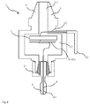
- a temperature measurement method and a temperature measurement device in a first embodiment of the present invention will be described below with reference to Fig. 1 to Fig. 3 .
- a temperature measurement device 1 includes a tubular tool holder 2, a collet nut 3, a cutting tool 4, a temperature measurement unit 5, an electronic substrate 6, a power feeding unit 7, and a cover member 8 that covers the electronic substrate 6 and the power feeding unit 7.
- the tool holder 2 is rotatable around a rotating axis (not illustrated), and has a hollow hole 20 extending from a front end to a rear end along the rotating axis.
- the tool holder 2 can hold the cutting tool 4 at the front end.
- the tool holder 2 has a communication hole 22 that communicates with the hollow hole 20 from an outer circumferential section 21. As illustrated in Fig. 1 , the communication hole 22 extends substantially orthogonal to the axial length of the tool holder 2.
- the collet nut 3 is incorporated near the front end of the tool holder 2, and acts as a holding member that can hold the cutting tool 4 at the front end of the tool holder 2.
- the cutting tool 4 may be formed of a drill, end mill, tap, or the like, and serves to cut a target.
- the cutting tool 4 illustrated in Fig. 1 has a through hole 40 formed by piercing.
- the through hole 40 is a hole that is coaxial with the hollow hole 20 of the tool holder 2, and is a hole to which the temperature measurement unit 5 is attached.
- the through hole 40 passes through an upper end to a lower end of the cutting tool.
- the through hole in this description also includes a semi-through hole extending from the upper end on the way to the lower end.
- the temperature measurement unit 5 may be formed of a temperature measurement element such as a thermocouple, a thermistor, or a platinum resistance thermometer sensor, and can be attached to the through hole 40 of the cutting tool 4. With being attached to the through hole 40, the temperature measurement unit 5 can measure, in real time, the temperature of the cutting tool 4 that rotates coaxially with the tool holder 2. The temperature measurement unit 5 can transmit a measurement result to the electronic substrate 6 through electric wiring (not illustrated).
- a temperature measurement element such as a thermocouple, a thermistor, or a platinum resistance thermometer sensor
- the electronic substrate 6 is provided on the outer circumferential section 21 of the tool holder 2, with being covered with the cover member 8.
- the electronic substrate 6 includes a temperature reception unit 60 and a transmission unit 61.
- the temperature reception unit 60 can receive, in real time, the temperature of the cutting tool 4 from the temperature measurement unit 5 through electric wiring (not illustrated).
- the transmission unit 61 can wirelessly transmit the temperature of the cutting tool 4, which is received by the temperature reception unit 60, to an external unit.
- the power feeding unit 7 is provided on the outer circumferential section 21 of the tool holder 2.
- the power feeding unit 7 may be formed of a charging or non-charging battery, and can feed power to the electronic substrate 6.
- Fig. 2 is a block diagram illustrating an example of a flow of an electric signal indicating the cutting tool temperature measured by the temperature measurement unit.
- a flow of an electric signal is indicated in a case where a thermocouple constitutes the temperature measurement unit 5.
- Each arrow in Fig. 2 represents a flow of the electric signal indicating the temperature of the cutting tool 4, which is measured by the thermocouple, according to the mode of the signal transmission path, wire communication is expressed as a solid line, and wireless communication is expressed as a broken line.
- a zero contact compensation circuit, a potential difference amplification unit, an A/D (analog/digital) converter, and an intra-device control circuit constitute the temperature reception unit 60.
- a controller and a wireless communication device constitute the transmission unit 61.
- a wireless reception and record output apparatus constitutes the external unit.
- the wireless reception and record output apparatus includes a wireless reception device, a serial USB (Universal Serial Bus) converter, a record and calculation device such as a personal computer, and an output device such as a display or a printer, from the upstream side to the downstream side along the flow of the electric signal.
- Examples of the wireless communication standard expressed as a broken line between the wireless reception devices in Fig. 2 include Wi-Fi (Wireless Fidelity), Blue-tooth (Bluetooth), wireless LAN (Local Area Network), and ZigBee (ZigBee).
- the cutting tool 4 held at the front end of the tool holder 2 that is rotatable around the rotating axis has the through hole 40 to which the temperature measurement unit 5 can be attached, by receiving the measurement result of the temperature measurement unit 5 by the electronic substrate 6, the temperature of the cutting tool 4 during actual processing of rotating coaxially with the tool holder 2 (actual cutting of the target) can be ascertained in real time.
- the cooling performance of cutting oil can be evaluated. More specifically, referring to the cutting tool temperature ascertained in real time, cutting oil with a small temperature rise can be determined to be cutting oil having a high cooling performance.
- the cooling performance of the cutting oil can be evaluated more accurately than conventional means. This enables easy selection of cutting oil having an excellent cooling performance, and contributes to development of cutting oil.
- the temperature measurement device 1 in this embodiment is different from the temperature measurement device of the first embodiment (See Fig. 1 ) in that a tool holder 2 includes a storage space 23 communicating with a hollow hole 20. As illustrated in Fig. 4 , a horizontal cross-sectional diameter of the storage space 23 is larger than a horizontal cross-sectional diameter of the hollow hole 20 so as to store an electronic substrate 6 and a power feeding unit 7. Further, the temperature measurement device 1 in this embodiment is different from the temperature measurement device in the first embodiment (See Fig.
- the tool holder 2 has a communication hole 22 that communicates with the hollow hole 20 from the outer circumferential section 21, and the transmission unit 61 is electrically connected to the temperature reception unit 60 of the electronic substrate 6 via the power feeding unit 7 using electric wiring extending inside the communication hole 22 and the hollow hole 20.
- a flow of the electric signal indicating the cutting tool temperature measured by the temperature measurement unit in this embodiment is different from the flow of the electric signal in the first embodiment (See Fig. 2 ).
- Fig. 5 is a block diagram illustrating an example of a flow of an electric signal indicating the cutting tool temperature measured by the temperature measurement unit.
- a flow of an electric signal is indicated in a case where a thermistor constitutes the temperature measurement unit 5.
- a detection circuit, an A/D converter, and a controller constitute the temperature reception unit 60.
- a wireless communication device such as a wireless transmission antenna constitutes the transmission unit 61.
- a wireless reception and record output apparatus constitutes the external unit.
- a flow of the electric signal in the wireless reception and record output apparatus is the same as the flow of the electric signal in the first embodiment (See Fig. 2 ) and thus, detailed description thereof is omitted.
- the second embodiment can achieve the same effect as the first embodiment.
- the storage space 23 in the tool holder 2 can store the electronic substrate 6 and the power feeding unit 7 in this embodiment, the cover member 8 required in the case where the electronic substrate 6 and the power feeding unit 7 are provided on the outer circumferential section 21 of the tool holder 2 can be omitted, reducing the number of components.
- the temperature measurement device 1 in this embodiment is different from the temperature measurement device in the second embodiment (See Fig. 4 ) in that a stress measurement unit 9 is attached to an outer circumferential section 21 of a tool holder 2. As illustrated in Fig. 6 , the stress measurement unit 9 is disposed above a storage space 23. As illustrated in Fig. 6 , the temperature measurement device 1 in this embodiment is different from the temperature measurement device in the second embodiment (See Fig. 4 ) in that an electronic substrate 6 further includes a stress reception unit 10, and a transmission unit 61 can wirelessly transmit a measurement result of the stress measurement unit 9 to an external unit.
- a flow of the electric signal indicating the cutting tool temperature measured by the temperature measurement unit (See Fig. 7 ) is the same as the flow of the electric signal in the first embodiment (See Fig. 2 ) and thus, detailed description is omitted.
- the stress measurement unit 9 can be formed of a quartz piezoelectric element, a piezoelectric element, or the like, and can measure an external stress exerted on a cutting tool 4. With being attached to the outer circumferential section 21 of the tool holder 2, the stress measurement unit 9 can measure the external stress exerted on the cutting tool 4, which rotates coaxially with the tool holder 2 in real time. Then, the stress measurement unit 9 can transmit a measurement result to a stress reception unit 10 of the electronic substrate 6 via electric wiring.
- the stress reception unit 10 is mounted in the electronic substrate 6, and can receive the measurement result of the stress measurement unit 9 via the electric wiring in real time.
- an electric signal indicating the stress measured by the stress measurement unit sequentially flows through a quartz piezoelectric element, a charge amplifier, an A/D converter, and a controller from the upstream side to the downstream side.
- a flow of an electric signal is indicated in a case where the quartz piezoelectric element constitutes the stress measurement unit 9.
- the charge amplifier and the A/D converter constitute the stress reception unit 10.
- a controller and a wireless communication device such as a wireless transmission antenna constitute the transmission unit 61.
- a wireless reception and record output apparatus constitutes the external unit.
- a flow of the electric signal in the wireless reception and record output apparatus is the same as the flow of the electric signal in the first embodiment (See Fig. 2 ) and thus, detailed description thereof is omitted.
- the third embodiment can achieve the same effect as the second embodiment.
- the stress measurement unit 9 can be attached to the outer circumferential section 21 of the tool holder 2 that is rotatable around the rotating axis (not illustrated), by receiving the measurement result of the stress measurement unit 9 by the stress reception unit 10 of the electronic substrate 6, the external stress exerted on the cutting tool 4 during actual processing of rotating coaxially with the tool holder 2 (actual cutting of the target) can be ascertained in real time.
- the temperature measurement device 1 in this embodiment has the same configuration as the temperature measurement device (See Fig. 6 ) in the third embodiment and thus, detailed description and illustration is omitted.
- a flow of an electric signal indicating the cutting tool temperature measured by the temperature measurement unit in this embodiment is the same as the flow of the electric signal in the second embodiment (See Fig. 5 ) and thus, detailed description is omitted.
- an electric signal indicating the stress measured by the stress measurement unit sequentially flows through a piezoelectric element, a detection circuit, an A/D converter, and a controller from the upstream side to the downstream side.
- a flow of an electric signal is indicated in a case where a piezoelectric element constitutes the stress measurement unit 9.
- the detection circuit, the A/D converter, and the controller constitute the stress reception unit 10.
- a wireless communication device such as a wireless transmission antenna constitutes the transmission unit 61.
- a wireless reception and record output apparatus constitute the external unit.
- a flow of the electric signal in the wireless reception and record output apparatus is the same as the flow of the electric signal in the second embodiment (See Fig. 5 ) and thus, detailed description is omitted.
- the fourth embodiment can achieve the same effect as the third embodiment.
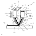
- a temperature measurement device 100 includes a tool holder 102 as a rotating holder, a welding torch 104 as a rotating tool, a temperature measurement unit 142, an electronic substrate 106, a power feeding unit 107, and a cover member 108 that covers the electronic substrate 106 and the power feeding unit 107.
- Fig. 9 schematically illustrates laser cladding.
- the temperature measurement device 100 includes the tool holder 102 and the welding torch 104 connected to the lower side of the tool holder 102 along a rotating axis X.
- the temperature measurement device 100 includes through holes 120, 105 connected to the tool holder 102 and the welding torch 104, respectively, and the through holes 120, 105 form a hollow laser beam path.
- a laser beam enters through an incidence port 110 that communicates the through hole 120 with the outside, is reflected on a mirror 112 in the vertically downward direction, and reaches a convex lens 114.
- the laser beam reaching the convex lens 114 is condensed, and the condensed beam is projected from an irradiation port 116 at the lower end of the through hole 105 in the welding torch 104. Then, the laser beam is condensed or defocused at a point immediately below the lower end of the welding torch 104 along the optical axis X, and is projected onto a surface of a base (base material) 130. At this time, the base 130 forms a molten pool 130a liquefied by melting at irradiation of the laser beam. However, the molten pool 130a has a small area.
- the welding torch 104 includes a cladding material powder feed pipe 133 that sends cladding material powder (also referred to as merely "cladding material”) 132 downward, a cooling water feed pipe 135 that sends cooling water 134 downward, and a shield gas feed pipe 137 that sends inert gas 136 downward, in this order from the central axis that is coaxial with the laser beam path X.
- cladding material powder feed pipe 133 that sends cladding material powder (also referred to as merely "cladding material”) 132 downward
- a cooling water feed pipe 135 that sends cooling water 134 downward
- shield gas feed pipe 137 that sends inert gas 136 downward, in this order from the central axis that is coaxial with the laser beam path X.
- the cladding material powder feed pipe 133 is disposed on the innermost side on a horizontal plane concentric with the laser beam path X, is converged from an upper end to the optical axis X following condensing of the laser beam, and communicates with the vicinity of the irradiation port 116 at the lower end of the welding torch 104.
- the cladding material powder feed pipe 133 may be one or more pipes disposed every predetermined angle on the horizontal plane, or may be a ring-like pipe that is circumferentially continuous. Accordingly, the cladding material powder feed pipe 133 pours the cladding material powder 132 from the upper end, and discharges to the position where the laser beam is projected onto the surface of the base 130, that is, the molten pool 130a on the surface of the base 130. The discharged cladding material powder 132 is heated with the laser beam and the molten pool 130a on the base 130 to form a clad layer 144 on the surface of the base 130 opposite to the moving direction of the welding torch 104 (See an arrow Y).
- the shield gas feed pipe 137 is disposed on the concentric outer side (coaxial outer side) of the cladding material powder feed pipe 133 on the horizontal plane with respect to the laser beam path X, is converged from an upper end to the optical axis X following condensing of the laser beam, and communicates with the vicinity of the irradiation port 116. Accordingly, the shield gas feed pipe 135 discharges the inert gas 136 such as argon gas flowing from the upper end at the lower end. The discharged inert gas 18 is sprayed to the cladding material powder 132 (and the clad layer 144), thereby stacking the clad layer 144 on the surface of the base 130 to apply an anti-oxidation processing.
- the cooling water feed pipe 137 is further disposed on the concentric outer side of the shield gas feed pipe 135, and its upper end communicates with the position above the lower end of the welding torch 104 by a predetermined distance.
- the clad layer 144 is rapidly cooled so as not to make the molten pool 13a on the base 130b large due to the laser beam, to form the uniformly distributed clad layer 144.
- the tool holder 102 is rotatable around the rotating axis X, and has the hollow through hole 120 extending from its upper end to its lower end along the rotating axis.
- the tool holder 102 is integrally connected to the welding torch 104 at the lower end.
- the tool holder 102 has a communication hole 141 that communicates with the through hole 120 at its outer circumferential section. As illustrated in Fig. 10, the communication hole 141 extends substantially orthogonal to the axial length of the tool holder 102.
- the temperature measurement unit 142 may be formed of a temperature measurement element such as a thermocouple, a thermistor, or a platinum resistance thermometer sensor, and can be attached to a position in the through hole (hollow hole) 105 of the welding torch 104, the temperature of which is to be measured. Since the through hole 105 includes the optical axis of the laser beam, the temperature measurement unit 142 is attached to an inner wall or the like of the through hole 105 so as not to interfere with the laser beam. With being attached to the through hole 105, the temperature measurement unit 142 can measure the temperature of the welding torch 104 located at a desired position, which rotates coaxially with the tool holder 102. The temperature measurement unit 142 can transmit a measurement result to the electronic substrate 106 via the electric wiring 141.
- a temperature measurement element such as a thermocouple, a thermistor, or a platinum resistance thermometer sensor
- the electronic substrate 106 is provided on the outer circumferential section of the tool holder 102.
- the electronic substrate 106 includes a temperature reception unit (reference number 60 in Fig. 2 ) and a transmission unit (reference number 61 in Fig. 2 ).
- the temperature reception unit can receive the temperature of the welding torch 104 from the temperature measurement unit 142 via the electric wiring 141 in real time.
- the transmission unit can wirelessly transmit the temperature of the welding torch 104, which is received by the temperature reception unit, to an external unit.
- the power feeding unit 107 is provided on the outer circumferential section of the tool holder 102.
- the power feeding unit 107 may be formed of a charging or non-charging battery, and can feed power to the electronic substrate 106.
- Modification examples of the temperature measurement device 1 for the cutting tool 4 in the second to fourth embodiments can be applied to the temperature measurement unit 142, the electronic substrate 106, and the power feeding unit 107 of the temperature measurement device 100 illustrated in Fig 9 .
- a storage unit for the electronic substrate 106 and so on may be provided in the tool holder 102.
- a piezoelectric element may be provided in the tool holder 102 to measure a stress exerted to the welding torch 104.
- the block diagram in Fig. 2 illustrating the flow of the electric signal indicating the temperature of the cutting tool 4 of the temperature measurement device 1 is referred.
- the flow of the electric signal is indicated in a case where a thermocouple constitutes the temperature measurement unit 5.
- Each arrow in Fig. 2 represents a flow of the electric signal indicating the temperature of the cutting tool 4, which is measured by the thermocouple, and according to the mode of the signal transmission path, wire communication is expressed as a solid line, and wireless communication is expressed as a broken line.
- a zero contact compensation circuit, a potential difference amplification unit, an A/D (analog/digital) converter, and an intra-device control circuit constitute the temperature reception unit 60.
- a controller and a wireless communication device constitute the transmission unit 61.
- a wireless reception and record output apparatus constitutes the external unit.
- the wireless reception and record output apparatus includes a wireless reception device, a serial USB (Universal Serial Bus) converter, a record and calculation device such as a personal computer, and an output device such as a display or a printer, from the upstream side to the downstream side along the flow of the electric signal.
- Examples of the wireless communication standard expressed as a broken line between the wireless reception devices in Fig. 2 include Wi-Fi (Wireless Fidelity), Blue-tooth (Bluetooth), wireless LAN (Local Area Network), and ZigBee (ZigBee).
- Modification examples (second to fourth embodiments) (See Fig. 5 , Fig. 7 , and Fig. 8 ) of the temperature measurement device 1 for the cutting tool 4 can be applied to a flow of the electric signal in the temperature measurement device 100 illustrated in Fig. 9 .
- the temperature measurement unit 142 is attached in a hollow region (through hole 105) in the welding torch 104 integrally connected to the lower end of the tool holder 102 that is rotatable around the rotating axis, by receiving a measurement result of the temperature measurement unit 142 by the electronic substrate 106, the temperature of the welding torch 104 during the actual processing of rotating coaxially with the tool holder 102 (actual welding) can be ascertained in real time.
- the cooling performances of the cooling water 134 and the cladding material 132 can be evaluated.
- the temperature measurement method and the temperature measurement device of the present invention can preferably apply to measurement of the temperature of various industrial rotating tools such as a cutting tool that cuts a target and a welding torch.
Landscapes
- Engineering & Computer Science (AREA)
- Mechanical Engineering (AREA)
- Physics & Mathematics (AREA)
- Optics & Photonics (AREA)
- Plasma & Fusion (AREA)
- General Physics & Mathematics (AREA)
- Human Computer Interaction (AREA)
- Manufacturing & Machinery (AREA)
- Automation & Control Theory (AREA)
- Arrangements For Transmission Of Measured Signals (AREA)
- Measuring Temperature Or Quantity Of Heat (AREA)
- Laser Beam Processing (AREA)
- Machine Tool Sensing Apparatuses (AREA)
Applications Claiming Priority (2)
| Application Number | Priority Date | Filing Date | Title |
|---|---|---|---|
| JP2013168372A JP6168695B2 (ja) | 2013-08-13 | 2013-08-13 | リアルタイム温度測定方法、及びリアルタイム温度測定装置 |
| PCT/JP2014/071334 WO2015022967A1 (ja) | 2013-08-13 | 2014-08-12 | 温度測定方法、及び、温度測定装置 |
Publications (3)
| Publication Number | Publication Date |
|---|---|
| EP3034236A1 true EP3034236A1 (de) | 2016-06-22 |
| EP3034236A4 EP3034236A4 (de) | 2017-04-19 |
| EP3034236B1 EP3034236B1 (de) | 2019-09-11 |
Family
ID=52468352
Family Applications (1)
| Application Number | Title | Priority Date | Filing Date |
|---|---|---|---|
| EP14836301.3A Active EP3034236B1 (de) | 2013-08-13 | 2014-08-12 | Temperaturmessverfahren und temperaturmessvorrichtung |
Country Status (6)
| Country | Link |
|---|---|
| US (1) | US10024737B2 (de) |
| EP (1) | EP3034236B1 (de) |
| JP (1) | JP6168695B2 (de) |
| KR (2) | KR20160006786A (de) |
| CN (1) | CN105339134B (de) |
| WO (1) | WO2015022967A1 (de) |
Cited By (1)
| Publication number | Priority date | Publication date | Assignee | Title |
|---|---|---|---|---|
| DE102017110647A1 (de) | 2017-05-16 | 2018-11-22 | Rheinisch-Westfälische Technische Hochschule (Rwth) Aachen | Schneidwerkzeug zum zerspanenden Bearbeiten eines Festkörpers |
Families Citing this family (27)
| Publication number | Priority date | Publication date | Assignee | Title |
|---|---|---|---|---|
| DE102014005315B3 (de) * | 2014-04-10 | 2015-06-11 | Grenzebach Maschinenbau Gmbh | Verfahren und Vorrichtung zur Erfassung der mechanischen Kräfte an der Schweißpin - Spitze bei dem Vorgang des Rührreibschweißens sowie Computerprogramm und maschinenlesbarer Träger mit einem Programmcode zur Durchführung des Verfahrens |
| JP6038426B1 (ja) * | 2015-01-07 | 2016-12-07 | 株式会社山本金属製作所 | 摩擦攪拌接合装置および摩擦攪拌接合に用いる回転ツール |
| US20180178293A1 (en) * | 2015-06-27 | 2018-06-28 | Yamamoto Metal Technos Co., Ltd. | Rotary machine tool equipped with sensor for real-time detection of state |
| JP5883978B1 (ja) * | 2015-08-06 | 2016-03-15 | 株式会社日立パワーソリューションズ | 摩擦攪拌接合装置および摩擦攪拌接合制御方法 |
| JP6853464B2 (ja) * | 2016-02-24 | 2021-03-31 | 株式会社山本金属製作所 | 疲労試験装置 |
| CN106271880B (zh) * | 2016-09-20 | 2018-07-31 | 天津大学 | 一种同时测量铣削过程铣刀及工件温度的测量系统 |
| JP6900613B2 (ja) * | 2016-09-27 | 2021-07-07 | 株式会社山本金属製作所 | 振動測定装置 |
| CN106595060A (zh) * | 2016-11-17 | 2017-04-26 | 中车长春轨道客车股份有限公司 | 热风枪的监控系统 |
| CN107083550A (zh) * | 2017-02-21 | 2017-08-22 | 机械科学研究总院先进制造技术研究中心 | 一种温度、送粉量可自动调试智能激光熔覆头 |
| CN106975984B (zh) * | 2017-05-05 | 2023-06-16 | 大连交通大学 | 一种基于薄膜热电偶的智能瞬态铣削测温刀具 |
| CN107030370A (zh) * | 2017-05-08 | 2017-08-11 | 宁波金凤焊割机械制造有限公司 | 金属新型焊接方法 |
| JP2019042831A (ja) * | 2017-08-31 | 2019-03-22 | 株式会社山本金属製作所 | 研切削加工装置用の測定・管理装置 |
| CN109202262B (zh) * | 2017-09-07 | 2020-12-25 | 中国航空制造技术研究院 | 一种搅拌摩擦焊接的搅拌头水冷却结构及冷却方法 |
| CN107779865B (zh) * | 2017-11-28 | 2019-11-15 | 西藏中轨科技有限责任公司 | 一种钢轨熔覆合金带火焰加热方法 |
| WO2020149280A1 (ja) * | 2019-01-15 | 2020-07-23 | 株式会社山本金属製作所 | リアルタイム加工状態表示装置 |
| DE102019203118B4 (de) * | 2019-03-07 | 2024-02-22 | Premium Aerotec Gmbh | Messwerkzeug zum Vermessen von Bohrungsdurchmessern sowie Werkzeugmaschine |
| DE102019112629A1 (de) * | 2019-05-14 | 2020-11-19 | Schunk Gmbh & Co. Kg Spann- Und Greiftechnik | Spanneinrichtung zum Spannen eines Bauteils, insbesondere zum Fixieren eines Werkzeugs an einer Werkzeugmaschine |
| US12059764B2 (en) | 2019-08-09 | 2024-08-13 | Yamamoto Metal Technos Co., Ltd. | Vibration measurement device |
| WO2021033671A1 (ja) * | 2019-08-19 | 2021-02-25 | 株式会社山本金属製作所 | ツールホルダユニット |
| JP7621582B2 (ja) * | 2019-08-19 | 2025-01-27 | 株式会社山本金属製作所 | 分割式ツールホルダユニット |
| CN118060605A (zh) * | 2019-09-03 | 2024-05-24 | 住友电气工业株式会社 | 切削工具、模块、切削工具单元以及切削系统 |
| EP3808503A1 (de) * | 2019-10-14 | 2021-04-21 | Albert Knebel Holding GmbH | Steuerplatine, werkzeughalter, werkzeug, korrespondierende verwendung und bearbeitungsmaschine |
| JP7432453B2 (ja) * | 2020-06-26 | 2024-02-16 | 本田技研工業株式会社 | 摩擦撹拌接合装置及び摩擦撹拌接合方法 |
| CN111906693B (zh) * | 2020-07-27 | 2022-02-08 | 郑州磨料磨具磨削研究所有限公司 | 一种磨削弧区热力集成测量装置及方法 |
| US20240217003A1 (en) | 2021-04-28 | 2024-07-04 | Sumitomo Electric Industries, Ltd. | Cutting tool |
| US11630005B1 (en) * | 2022-01-13 | 2023-04-18 | Eli Yudkevich | Machining monitor and a method for monitoring a machining of an object |
| CN114689197B (zh) * | 2022-05-31 | 2022-10-25 | 成都飞机工业(集团)有限责任公司 | 一种用于金属表面功能再造的在线测温装置 |
Family Cites Families (23)
| Publication number | Priority date | Publication date | Assignee | Title |
|---|---|---|---|---|
| FR1223607A (fr) * | 1959-01-31 | 1960-06-17 | Dispositif destiné à empêcher des dilatations locales dans des organes de machines dans lesquels tournent des broches porte-outils de grande capacité | |
| DE2630047C3 (de) * | 1976-07-03 | 1981-04-23 | Gebr. Heller Maschinenfabrik GmbH, 7440 Nürtingen | Fräswerkzeug zur Bearbeitung von Kurbelwellen und Kurbelwellenfräsmaschine zur Verwendung dieses Fräswerkzeuges |
| JPS58149113A (ja) * | 1982-02-25 | 1983-09-05 | Kiyoshi Hajikano | センサ−付きドリル |
| JPH0231257Y2 (de) * | 1986-06-13 | 1990-08-23 | ||
| CN2087551U (zh) * | 1991-03-13 | 1991-10-30 | 浙江大学 | 能显示切削刀具温度场的装置 |
| JPH05288611A (ja) * | 1992-04-13 | 1993-11-02 | Japan Energy Corp | 温度測定装置 |
| US5449882A (en) * | 1993-03-15 | 1995-09-12 | Reliant Laser Corporation | Mirror-based laser-processing system with temperature and position control of moving laser spot |
| KR950005451A (ko) * | 1993-08-05 | 1995-03-20 | 이장무 | 다중센서와 비젼 장치를 복합적으로 이용한 엔.시(nc) 절삭시스템의 실시간 공구상태 감시방법 |
| US5516285A (en) * | 1993-09-27 | 1996-05-14 | Yacker; Miles J. | Temperature gauge for surgical drills and method employing same |
| JPH07198429A (ja) * | 1993-12-28 | 1995-08-01 | Yahata Shiyoten:Kk | 波動情報変換装置 |
| US5573335A (en) * | 1994-05-25 | 1996-11-12 | Schinazi; Robert | Thin film temperature sensing device for measuring the operating temperature of a cutting tool |
| KR0174595B1 (ko) * | 1995-07-01 | 1999-05-15 | 윤덕용 | 절삭공구의 절삭력 측정구조 |
| DE19738229A1 (de) * | 1997-09-02 | 1999-03-04 | Bilz Otto Werkzeug | Werkzeug oder Werkzeughalter |
| JP3385473B2 (ja) * | 2000-12-14 | 2003-03-10 | 島根大学長 | 被削材の切削時の工具刃先温度の測定方法及びその装置 |
| JP3801862B2 (ja) * | 2000-12-27 | 2006-07-26 | 株式会社日研工作所 | 流体通路を備えた工具ホルダ |
| CN2652590Y (zh) * | 2003-10-10 | 2004-11-03 | 华南理工大学 | 刀具高速旋转时测温装置 |
| DE112005003148T5 (de) * | 2004-12-17 | 2007-10-31 | Milwaukee Electric Tool Corp., Brookfield | Intelligentes Zubehör für Elektrowerkzeuge |
| WO2006067398A1 (en) * | 2004-12-20 | 2006-06-29 | Renishaw Plc | Machine and control system |
| GB2438877A (en) * | 2006-06-07 | 2007-12-12 | Anglia Polytechnic University | An environment sensing power tool and control system |
| JP5822441B2 (ja) * | 2010-07-13 | 2015-11-24 | 株式会社幸和電熱計器 | 切削加工評価装置 |
| JP2012092205A (ja) | 2010-10-26 | 2012-05-17 | Nisshin Seiki Kk | 機械加工用油剤 |
| FR2978932B1 (fr) * | 2011-08-08 | 2014-05-09 | Snecma | Machine d'usinage |
| CN103128599B (zh) * | 2013-03-06 | 2015-03-04 | 上海交通大学 | 一种用于高速钻削加工的切削温度监测装置 |
-
2013
- 2013-08-13 JP JP2013168372A patent/JP6168695B2/ja active Active
-
2014
- 2014-08-12 WO PCT/JP2014/071334 patent/WO2015022967A1/ja not_active Ceased
- 2014-08-12 KR KR1020157035235A patent/KR20160006786A/ko not_active Ceased
- 2014-08-12 CN CN201480032405.1A patent/CN105339134B/zh active Active
- 2014-08-12 EP EP14836301.3A patent/EP3034236B1/de active Active
- 2014-08-12 KR KR1020187030914A patent/KR102055518B1/ko not_active Expired - Fee Related
-
2015
- 2015-12-14 US US14/967,365 patent/US10024737B2/en active Active
Non-Patent Citations (1)
| Title |
|---|
| See references of WO2015022967A1 * |
Cited By (1)
| Publication number | Priority date | Publication date | Assignee | Title |
|---|---|---|---|---|
| DE102017110647A1 (de) | 2017-05-16 | 2018-11-22 | Rheinisch-Westfälische Technische Hochschule (Rwth) Aachen | Schneidwerkzeug zum zerspanenden Bearbeiten eines Festkörpers |
Also Published As
| Publication number | Publication date |
|---|---|
| WO2015022967A1 (ja) | 2015-02-19 |
| US10024737B2 (en) | 2018-07-17 |
| KR20160006786A (ko) | 2016-01-19 |
| JP2015036174A (ja) | 2015-02-23 |
| KR20180118826A (ko) | 2018-10-31 |
| EP3034236A4 (de) | 2017-04-19 |
| JP6168695B2 (ja) | 2017-07-26 |
| KR102055518B1 (ko) | 2019-12-12 |
| US20160097687A1 (en) | 2016-04-07 |
| CN105339134B (zh) | 2018-02-27 |
| CN105339134A (zh) | 2016-02-17 |
| EP3034236B1 (de) | 2019-09-11 |
Similar Documents
| Publication | Publication Date | Title |
|---|---|---|
| EP3034236B1 (de) | Temperaturmessverfahren und temperaturmessvorrichtung | |
| US20180178293A1 (en) | Rotary machine tool equipped with sensor for real-time detection of state | |
| CN102554702B (zh) | 刀杆式旋铣刀片切削力及温度测量装置 | |
| EP3747597B1 (de) | Drehwerkzeug und drehverfahren | |
| JP6931150B2 (ja) | 温度測定装置 | |
| CN109396958B (zh) | 结合机床的主轴使用几何探针的方法及执行此方法的机床 | |
| US20180243873A1 (en) | Temperature measurement device | |
| RU2339923C2 (ru) | Градуировка и измерение температур в расплавах посредством оптических волокон | |
| CN104942318A (zh) | 一种智能瞬态切削测温刀具、制作方法及其测温方法 | |
| CN109676435B (zh) | 一种铣削温度测试装置、系统及方法 | |
| JP2017140696A (ja) | リアルタイム温度測定方法、及び、リアルタイム温度測定装置 | |
| Moreira et al. | Temperature field acquisition during gas metal arc welding using thermocouples, thermography and fibre Bragg grating sensors | |
| Subramani et al. | Temperature distribution in a hollow cylindrical workpiece during machining: theoretical model and experimental results | |
| CN103353466A (zh) | 一种固态金属热流密度的测量方法 | |
| CN113210686A (zh) | 一种可跟随刀-屑接触磨损的瞬态铣削温度测试装置 | |
| CN101936908A (zh) | 一种用于真空熔炼炉内钢液成分在线监测装置的检测探头 | |
| CN116372401A (zh) | 一种锂离子电池极耳激光焊接质量实时检测的系统及方法 | |
| CN114603493A (zh) | 一种磨削温度在线测量的砂轮 | |
| CN207014123U (zh) | 基于红外热成像的机床切削热监控系统 | |
| CN223352558U (zh) | 一种具有模具温度监测报警功能的扁线拉丝设备 | |
| WO2022202497A1 (ja) | 旋削工具 | |
| Guthy et al. | A review of temperature measurement methods for twist drilling processes | |
| Fernandes et al. | Real-time temperature monitoring during titanium alloy machining with cutting tools integrating novel thin-film sensors | |
| CN113794089A (zh) | 激光器调试方法、激光器调试系统和计算机可读存储介质 | |
| CN1936527A (zh) | 消耗型热电偶及其测温系统在线校准装置 |
Legal Events
| Date | Code | Title | Description |
|---|---|---|---|
| PUAI | Public reference made under article 153(3) epc to a published international application that has entered the european phase |
Free format text: ORIGINAL CODE: 0009012 |
|
| 17P | Request for examination filed |
Effective date: 20151214 |
|
| AK | Designated contracting states |
Kind code of ref document: A1 Designated state(s): AL AT BE BG CH CY CZ DE DK EE ES FI FR GB GR HR HU IE IS IT LI LT LU LV MC MK MT NL NO PL PT RO RS SE SI SK SM TR |
|
| AX | Request for extension of the european patent |
Extension state: BA ME |
|
| DAX | Request for extension of the european patent (deleted) | ||
| A4 | Supplementary search report drawn up and despatched |
Effective date: 20170316 |
|
| RIC1 | Information provided on ipc code assigned before grant |
Ipc: B23K 20/12 20060101ALI20170311BHEP Ipc: B23K 26/00 20140101ALI20170311BHEP Ipc: B23K 26/342 20140101ALI20170311BHEP Ipc: B23K 26/03 20060101ALI20170311BHEP Ipc: B23Q 17/09 20060101AFI20170311BHEP Ipc: B23K 9/095 20060101ALI20170311BHEP Ipc: B23Q 5/04 20060101ALI20170311BHEP |
|
| STAA | Information on the status of an ep patent application or granted ep patent |
Free format text: STATUS: EXAMINATION IS IN PROGRESS |
|
| 17Q | First examination report despatched |
Effective date: 20180719 |
|
| GRAP | Despatch of communication of intention to grant a patent |
Free format text: ORIGINAL CODE: EPIDOSNIGR1 |
|
| STAA | Information on the status of an ep patent application or granted ep patent |
Free format text: STATUS: GRANT OF PATENT IS INTENDED |
|
| INTG | Intention to grant announced |
Effective date: 20190322 |
|
| GRAS | Grant fee paid |
Free format text: ORIGINAL CODE: EPIDOSNIGR3 |
|
| GRAA | (expected) grant |
Free format text: ORIGINAL CODE: 0009210 |
|
| STAA | Information on the status of an ep patent application or granted ep patent |
Free format text: STATUS: THE PATENT HAS BEEN GRANTED |
|
| AK | Designated contracting states |
Kind code of ref document: B1 Designated state(s): AL AT BE BG CH CY CZ DE DK EE ES FI FR GB GR HR HU IE IS IT LI LT LU LV MC MK MT NL NO PL PT RO RS SE SI SK SM TR |
|
| REG | Reference to a national code |
Ref country code: GB Ref legal event code: FG4D |
|
| REG | Reference to a national code |
Ref country code: CH Ref legal event code: EP |
|
| REG | Reference to a national code |
Ref country code: AT Ref legal event code: REF Ref document number: 1177823 Country of ref document: AT Kind code of ref document: T Effective date: 20190915 |
|
| REG | Reference to a national code |
Ref country code: DE Ref legal event code: R096 Ref document number: 602014053598 Country of ref document: DE |
|
| REG | Reference to a national code |
Ref country code: IE Ref legal event code: FG4D |
|
| REG | Reference to a national code |
Ref country code: NL Ref legal event code: MP Effective date: 20190911 |
|
| REG | Reference to a national code |
Ref country code: LT Ref legal event code: MG4D |
|
| PG25 | Lapsed in a contracting state [announced via postgrant information from national office to epo] |
Ref country code: HR Free format text: LAPSE BECAUSE OF FAILURE TO SUBMIT A TRANSLATION OF THE DESCRIPTION OR TO PAY THE FEE WITHIN THE PRESCRIBED TIME-LIMIT Effective date: 20190911 Ref country code: SE Free format text: LAPSE BECAUSE OF FAILURE TO SUBMIT A TRANSLATION OF THE DESCRIPTION OR TO PAY THE FEE WITHIN THE PRESCRIBED TIME-LIMIT Effective date: 20190911 Ref country code: FI Free format text: LAPSE BECAUSE OF FAILURE TO SUBMIT A TRANSLATION OF THE DESCRIPTION OR TO PAY THE FEE WITHIN THE PRESCRIBED TIME-LIMIT Effective date: 20190911 Ref country code: NO Free format text: LAPSE BECAUSE OF FAILURE TO SUBMIT A TRANSLATION OF THE DESCRIPTION OR TO PAY THE FEE WITHIN THE PRESCRIBED TIME-LIMIT Effective date: 20191211 Ref country code: BG Free format text: LAPSE BECAUSE OF FAILURE TO SUBMIT A TRANSLATION OF THE DESCRIPTION OR TO PAY THE FEE WITHIN THE PRESCRIBED TIME-LIMIT Effective date: 20191211 Ref country code: LT Free format text: LAPSE BECAUSE OF FAILURE TO SUBMIT A TRANSLATION OF THE DESCRIPTION OR TO PAY THE FEE WITHIN THE PRESCRIBED TIME-LIMIT Effective date: 20190911 |
|
| PG25 | Lapsed in a contracting state [announced via postgrant information from national office to epo] |
Ref country code: RS Free format text: LAPSE BECAUSE OF FAILURE TO SUBMIT A TRANSLATION OF THE DESCRIPTION OR TO PAY THE FEE WITHIN THE PRESCRIBED TIME-LIMIT Effective date: 20190911 Ref country code: LV Free format text: LAPSE BECAUSE OF FAILURE TO SUBMIT A TRANSLATION OF THE DESCRIPTION OR TO PAY THE FEE WITHIN THE PRESCRIBED TIME-LIMIT Effective date: 20190911 Ref country code: GR Free format text: LAPSE BECAUSE OF FAILURE TO SUBMIT A TRANSLATION OF THE DESCRIPTION OR TO PAY THE FEE WITHIN THE PRESCRIBED TIME-LIMIT Effective date: 20191212 Ref country code: AL Free format text: LAPSE BECAUSE OF FAILURE TO SUBMIT A TRANSLATION OF THE DESCRIPTION OR TO PAY THE FEE WITHIN THE PRESCRIBED TIME-LIMIT Effective date: 20190911 Ref country code: ES Free format text: LAPSE BECAUSE OF FAILURE TO SUBMIT A TRANSLATION OF THE DESCRIPTION OR TO PAY THE FEE WITHIN THE PRESCRIBED TIME-LIMIT Effective date: 20190911 |
|
| REG | Reference to a national code |
Ref country code: AT Ref legal event code: MK05 Ref document number: 1177823 Country of ref document: AT Kind code of ref document: T Effective date: 20190911 |
|
| PG25 | Lapsed in a contracting state [announced via postgrant information from national office to epo] |
Ref country code: PL Free format text: LAPSE BECAUSE OF FAILURE TO SUBMIT A TRANSLATION OF THE DESCRIPTION OR TO PAY THE FEE WITHIN THE PRESCRIBED TIME-LIMIT Effective date: 20190911 Ref country code: NL Free format text: LAPSE BECAUSE OF FAILURE TO SUBMIT A TRANSLATION OF THE DESCRIPTION OR TO PAY THE FEE WITHIN THE PRESCRIBED TIME-LIMIT Effective date: 20190911 Ref country code: RO Free format text: LAPSE BECAUSE OF FAILURE TO SUBMIT A TRANSLATION OF THE DESCRIPTION OR TO PAY THE FEE WITHIN THE PRESCRIBED TIME-LIMIT Effective date: 20190911 Ref country code: PT Free format text: LAPSE BECAUSE OF FAILURE TO SUBMIT A TRANSLATION OF THE DESCRIPTION OR TO PAY THE FEE WITHIN THE PRESCRIBED TIME-LIMIT Effective date: 20200113 Ref country code: IT Free format text: LAPSE BECAUSE OF FAILURE TO SUBMIT A TRANSLATION OF THE DESCRIPTION OR TO PAY THE FEE WITHIN THE PRESCRIBED TIME-LIMIT Effective date: 20190911 Ref country code: EE Free format text: LAPSE BECAUSE OF FAILURE TO SUBMIT A TRANSLATION OF THE DESCRIPTION OR TO PAY THE FEE WITHIN THE PRESCRIBED TIME-LIMIT Effective date: 20190911 Ref country code: AT Free format text: LAPSE BECAUSE OF FAILURE TO SUBMIT A TRANSLATION OF THE DESCRIPTION OR TO PAY THE FEE WITHIN THE PRESCRIBED TIME-LIMIT Effective date: 20190911 |
|
| PG25 | Lapsed in a contracting state [announced via postgrant information from national office to epo] |
Ref country code: SM Free format text: LAPSE BECAUSE OF FAILURE TO SUBMIT A TRANSLATION OF THE DESCRIPTION OR TO PAY THE FEE WITHIN THE PRESCRIBED TIME-LIMIT Effective date: 20190911 Ref country code: CZ Free format text: LAPSE BECAUSE OF FAILURE TO SUBMIT A TRANSLATION OF THE DESCRIPTION OR TO PAY THE FEE WITHIN THE PRESCRIBED TIME-LIMIT Effective date: 20190911 Ref country code: IS Free format text: LAPSE BECAUSE OF FAILURE TO SUBMIT A TRANSLATION OF THE DESCRIPTION OR TO PAY THE FEE WITHIN THE PRESCRIBED TIME-LIMIT Effective date: 20200224 Ref country code: SK Free format text: LAPSE BECAUSE OF FAILURE TO SUBMIT A TRANSLATION OF THE DESCRIPTION OR TO PAY THE FEE WITHIN THE PRESCRIBED TIME-LIMIT Effective date: 20190911 |
|
| REG | Reference to a national code |
Ref country code: DE Ref legal event code: R097 Ref document number: 602014053598 Country of ref document: DE |
|
| PLBE | No opposition filed within time limit |
Free format text: ORIGINAL CODE: 0009261 |
|
| STAA | Information on the status of an ep patent application or granted ep patent |
Free format text: STATUS: NO OPPOSITION FILED WITHIN TIME LIMIT |
|
| PG2D | Information on lapse in contracting state deleted |
Ref country code: IS |
|
| PG25 | Lapsed in a contracting state [announced via postgrant information from national office to epo] |
Ref country code: DK Free format text: LAPSE BECAUSE OF FAILURE TO SUBMIT A TRANSLATION OF THE DESCRIPTION OR TO PAY THE FEE WITHIN THE PRESCRIBED TIME-LIMIT Effective date: 20190911 Ref country code: IS Free format text: LAPSE BECAUSE OF FAILURE TO SUBMIT A TRANSLATION OF THE DESCRIPTION OR TO PAY THE FEE WITHIN THE PRESCRIBED TIME-LIMIT Effective date: 20200112 |
|
| 26N | No opposition filed |
Effective date: 20200615 |
|
| PG25 | Lapsed in a contracting state [announced via postgrant information from national office to epo] |
Ref country code: SI Free format text: LAPSE BECAUSE OF FAILURE TO SUBMIT A TRANSLATION OF THE DESCRIPTION OR TO PAY THE FEE WITHIN THE PRESCRIBED TIME-LIMIT Effective date: 20190911 |
|
| PG25 | Lapsed in a contracting state [announced via postgrant information from national office to epo] |
Ref country code: MC Free format text: LAPSE BECAUSE OF FAILURE TO SUBMIT A TRANSLATION OF THE DESCRIPTION OR TO PAY THE FEE WITHIN THE PRESCRIBED TIME-LIMIT Effective date: 20190911 |
|
| REG | Reference to a national code |
Ref country code: CH Ref legal event code: PL |
|
| PG25 | Lapsed in a contracting state [announced via postgrant information from national office to epo] |
Ref country code: CH Free format text: LAPSE BECAUSE OF NON-PAYMENT OF DUE FEES Effective date: 20200831 Ref country code: LU Free format text: LAPSE BECAUSE OF NON-PAYMENT OF DUE FEES Effective date: 20200812 Ref country code: LI Free format text: LAPSE BECAUSE OF NON-PAYMENT OF DUE FEES Effective date: 20200831 |
|
| REG | Reference to a national code |
Ref country code: BE Ref legal event code: MM Effective date: 20200831 |
|
| PG25 | Lapsed in a contracting state [announced via postgrant information from national office to epo] |
Ref country code: BE Free format text: LAPSE BECAUSE OF NON-PAYMENT OF DUE FEES Effective date: 20200831 Ref country code: IE Free format text: LAPSE BECAUSE OF NON-PAYMENT OF DUE FEES Effective date: 20200812 |
|
| PG25 | Lapsed in a contracting state [announced via postgrant information from national office to epo] |
Ref country code: TR Free format text: LAPSE BECAUSE OF FAILURE TO SUBMIT A TRANSLATION OF THE DESCRIPTION OR TO PAY THE FEE WITHIN THE PRESCRIBED TIME-LIMIT Effective date: 20190911 Ref country code: MT Free format text: LAPSE BECAUSE OF FAILURE TO SUBMIT A TRANSLATION OF THE DESCRIPTION OR TO PAY THE FEE WITHIN THE PRESCRIBED TIME-LIMIT Effective date: 20190911 Ref country code: CY Free format text: LAPSE BECAUSE OF FAILURE TO SUBMIT A TRANSLATION OF THE DESCRIPTION OR TO PAY THE FEE WITHIN THE PRESCRIBED TIME-LIMIT Effective date: 20190911 |
|
| PG25 | Lapsed in a contracting state [announced via postgrant information from national office to epo] |
Ref country code: MK Free format text: LAPSE BECAUSE OF FAILURE TO SUBMIT A TRANSLATION OF THE DESCRIPTION OR TO PAY THE FEE WITHIN THE PRESCRIBED TIME-LIMIT Effective date: 20190911 |
|
| PGFP | Annual fee paid to national office [announced via postgrant information from national office to epo] |
Ref country code: DE Payment date: 20250904 Year of fee payment: 12 |
|
| PGFP | Annual fee paid to national office [announced via postgrant information from national office to epo] |
Ref country code: GB Payment date: 20250828 Year of fee payment: 12 |
|
| PGFP | Annual fee paid to national office [announced via postgrant information from national office to epo] |
Ref country code: FR Payment date: 20250828 Year of fee payment: 12 |