EP3034252A1 - Gerät zum schneiden von lebensmitteln in scheiben, stifte, würfel oder sehr feine streifen - Google Patents
Gerät zum schneiden von lebensmitteln in scheiben, stifte, würfel oder sehr feine streifen Download PDFInfo
- Publication number
- EP3034252A1 EP3034252A1 EP16153293.2A EP16153293A EP3034252A1 EP 3034252 A1 EP3034252 A1 EP 3034252A1 EP 16153293 A EP16153293 A EP 16153293A EP 3034252 A1 EP3034252 A1 EP 3034252A1
- Authority
- EP
- European Patent Office
- Prior art keywords
- cutting
- cutting tool
- food
- complementary
- movable
- Prior art date
- Legal status (The legal status is an assumption and is not a legal conclusion. Google has not performed a legal analysis and makes no representation as to the accuracy of the status listed.)
- Granted
Links
Images



Classifications
-
- B—PERFORMING OPERATIONS; TRANSPORTING
- B26—HAND CUTTING TOOLS; CUTTING; SEVERING
- B26D—CUTTING; DETAILS COMMON TO MACHINES FOR PERFORATING, PUNCHING, CUTTING-OUT, STAMPING-OUT OR SEVERING
- B26D3/00—Cutting work characterised by the nature of the cut made; Apparatus therefor
- B26D3/18—Cutting work characterised by the nature of the cut made; Apparatus therefor to obtain cubes or the like
- B26D3/20—Cutting work characterised by the nature of the cut made; Apparatus therefor to obtain cubes or the like using reciprocating knives
-
- B—PERFORMING OPERATIONS; TRANSPORTING
- B26—HAND CUTTING TOOLS; CUTTING; SEVERING
- B26D—CUTTING; DETAILS COMMON TO MACHINES FOR PERFORATING, PUNCHING, CUTTING-OUT, STAMPING-OUT OR SEVERING
- B26D1/00—Cutting through work characterised by the nature or movement of the cutting member or particular materials not otherwise provided for; Apparatus or machines therefor; Cutting members therefor
- B26D1/0006—Cutting members therefor
- B26D2001/0053—Cutting members therefor having a special cutting edge section or blade section
-
- B—PERFORMING OPERATIONS; TRANSPORTING
- B26—HAND CUTTING TOOLS; CUTTING; SEVERING
- B26D—CUTTING; DETAILS COMMON TO MACHINES FOR PERFORATING, PUNCHING, CUTTING-OUT, STAMPING-OUT OR SEVERING
- B26D7/00—Details of apparatus for cutting, cutting-out, stamping-out, punching, perforating, or severing by means other than cutting
- B26D7/06—Arrangements for feeding or delivering work of other than sheet, web, or filamentary form
- B26D7/065—Arrangements for feeding or delivering work of other than sheet, web, or filamentary form by the cutter itself because of its form
Definitions
- the present invention relates to the technical field of household cutting devices, manual or motorized, also called mandolins, used to cut food, including slices or filaments, by reciprocating a cutting tool.
- a patent US 5,445,332 has proposed a household linear cutting apparatus comprising a frame defining a cutting zone which is fixed relative to the frame.
- the apparatus also comprises a feed chute to cut that is secured to the frame and located above the cutting area being fixed relative to the cutting area and which extends in a direction ⁇ .
- the apparatus is provided with a cutting tool movable relative to the frame in the cutting area.
- the movable cutting tool is moved by motorized operating means in reciprocating motion in a cutting plane substantially normal to the direction of extension of the chute.
- Such a household linear cutting device then allows to cut food slices or to grate them to form filaments.
- this device is not able to cut food into cubes or sticks as is necessary for example for the realization of a julienne or a macedonia of vegetables.
- the combination of the cutting tool that is movable and the complementary cutting tool that is fixed allows, by the only movement of the cutting tool, to cut food into cubes or sticks, which was not not possible with the cutting apparatus according to the prior art.
- the main cutting edge of the cutting tool is used to cut a slice of the feed introduced into the chute, while the pressure shoe forces, as and when advancement of the tool of cutting, the slice being cut against the fixed complementary cutting tool, so as to divide this slice into rods or cubes.
- the pressure shoe has a thickness, measured between the cutting plane and the end of the inclined surface opposite the main cutting edge, greater than or equal to 4 mm.
- a thickness of the pressure shoe makes it possible to cut vegetable sticks or cubes having a size sufficient for the realization of a julienne for example.
- the pressure shoe has in the extension of the bevel a heel substantially parallel to the cutting plane. This heel makes it possible to squeeze the food to be cut against the fixed complementary cutting tool.
- the mobile cutting tool comprises a second main cutting edge substantially parallel to the cutting plane and arranged to work in the return direction, said second main cutting stop being associated with another pressure shoe.
- the implementation of a second main cutting edge allows cutting in the two phases of the reciprocating movement, so as to increase the cutting rate of the apparatus according to the invention.
- the fixed complementary cutting tool comprises a first series of cutting members substantially parallel to each other and forming an angle with the direction of movement of the movable cutting tool.
- the cutting members thus contribute to holding the sliced food by the main cutting edge.
- the cutting members of the first series are substantially perpendicular to the direction of movement of the movable cutting tool.
- the fixed complementary cutting tool comprises a second series of other cutting members substantially parallel to each other, the first series of cutting members and the second series of other cutting members defining a cutting grid.
- the cutting members of the second series are substantially perpendicular to the cutting members of the first series. It is thus formed a cutting grid adapted to the production of cubes.
- the movable cutting tool comprises at least one secondary cutting blade which is substantially perpendicular to the main cutting edge and substantially parallel to the direction of extension of the chute.
- Such an embodiment of the movable cutting tool makes it possible to cut into a slice the slice of food cut by the main cutting edge.
- the fixed complementary cutting tool comprises a bearing abutment for a food which extends transversely to the cutting plane and which is substantially opposite the main cutting edge.
- the implementation of such a support abutment prevents the food slice cut by the first cutting edge does not follow the movement of the cutting tool under the effect of the thrust exerted by the pressure shoe.
- the stop is movable between a working position in which the stop is opposite the main cutting edge and a withdrawal position in which the stop is erased below the cutting plane.
- This variant allows the abutment to be erased during the passage of the pressure shoe, so that the main cutting edge of the movable cutting tool can move beyond the stop.
- the stop can then be enslaved in the extended position by elastic return means.
- the fixed complementary cutting tool and the movable cutting tool are connected to each other by a slide connection ensuring the guiding of the movable cutting tool during its reciprocating movements.
- the fixed complementary cutting tool and the movable cutting tool are integral and form an assembly removably adapted to the frame.
- the mobile cutting tool can not be mounted on the frame without the fixed complementary cutting tool.
- the food cutting apparatus comprises operating means that can be operated manually by a user of the apparatus.
- the operating means may then comprise for example a handle secured to the movable cutting tool.
- the food cutting apparatus comprises motorized operating means comprising a drive member complementary to a coupling member of the movable cutting tool.
- the motorized operating means can then be arranged in the frame or in the cover.
- the motorized operating means may also include a motorized housing independent of the frame and the cover.
- the apparatus comprises means for identifying the fixed complementary cutting tool and the motorized operating means are adapted to modify their operating speed as a function of the identification of the cutting tool. complementary.
- identification means makes it possible, for example, to implement a fast cutting speed in the absence of the fixed complementary cutting tool and a slow cutting speed in the presence of the complementary cutting tool. fixed.
- the food cutting apparatus is associated with motorized operating means comprising a motorized housing independent of the frame and the cover.
- the food cutter thus forms an accessory used with the motorized housing.
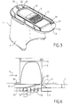
- a food cutting apparatus as illustrated in Figures 1 to 3 , comprises a frame 1 formed, according to the illustrated example, of a trunk 2 intended to be placed on a support and a head 3 which extends cantilevered from the trunk 2 and which delimits, laterally to the trunk 2, a cutting zone 4.
- the cutting zone 4 is located in height relative to the support on which the frame 1 rests, so that it is possible to place a container under the cutting zone. 4 to collect the cut food by means of cutting tools located in said cutting zone 4, as will appear later.
- the face 2f of the trunk facing the cutting zone 4 is concave so as to marry the rounded shape of a bowl, a bowl or a plate so that they are correctly positioned under the cutting area 4.
- the food cutting apparatus also comprises a food chute 5 to cut which is integral with the frame 1 and is located above the cutting zone 4.
- the chute 5 is integrated in a removable cover 6 which covers the head 3 so that the cutting zone 4 and the cutting tools therein are not accessible from above.
- the chute 5 extends in a substantially vertical direction.
- the chute 5 is fixed relative to the cutting zone 4.
- the cutting zone 4 is fixed relative to the frame 1.
- the apparatus comprises a cutting tool 10 and a complementary cutting tool 11 which, according to the illustrated example, are removable.
- the cutting tool 10 is movable in the cutting zone 4, while the complementary cutting tool 11 is fixed relative to the frame 1 while being located in the cutting zone 4 under the chute 5 so that the cutting tool 10 moves between the chute 5 and the complementary cutting tool 11.
- the cutting tool 10 is, in this case, movable in translation in a direction D substantially normal to the direction ⁇ of extension of the chute 5.
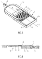
- the complementary cutting tool 11 comprises, as shown more particularly by the Figures 4 and 5 , a body 12 of generally parallelepipedal shape.
- the body 12 comprises, in its region intended to be placed in the cutting zone 4 opposite the chute 5, a first series of cutting members 13 parallel to each other.
- Each cutting member 13 then extends in a plane, on the one hand, substantially parallel to the direction ⁇ of extension of the chute and, on the other hand, substantially perpendicular to the direction D of displacement of the tool of The cutting members 13 thus form an angle with the direction of movement of the movable cutting tool 10.
- each cutting member 13 comprises a cutting edge 14 facing upwards in the direction of the chute 5.
- the cutting tool 10 comprises a body 22 provided with two lateral grooves 23 intended to engage on two longitudinal tongues 24 carried by the body 12 of the complementary cutting tool 11, so that the cutting tool 10 and the complementary cutting tool 11 are connected to each other by a slide connection guiding the cutting tool 10 during its reciprocating movements.
- the cutting tool 10 and the complementary cutting tool 11 are integral and form an assembly removably adapted to the frame 1.
- the body 22 carries a blade 25 which is in front of a solid portion 26 of the body 22 and at the rear of a cutting window 27 delimited by the body 22.
- the blade 25 comprises a main cutting edge 28 in the plane of section C.
- the cutting plane C is substantially normal to the direction ⁇ of extension of the chute 5.
- the cutting tool 10 also comprises a pressing shoe 29 which is derived from the main cutting edge 28 and arranged on the side of the complementary cutting tool 11.
- the pressing shoe 29 comprises a bevel 30 inclined from the main cutting stop 28 towards the inside of the cutting tool 10 and in a direction opposite to the direction of work indicated by the arrow F1.
- the bevel 30 is extended by a heel 31 substantially parallel to the plane of section C.
- the pressing shoe 29 has, according to the illustrated example, a thickness h sufficient to occupy most of the space between the complementary cutting tool 11 and the lower end of the chute 5.
- the thickness h, measured between the cutting plane and the end of the bevel 30 opposite the main cutting edge 28, is preferably greater than or equal to 4 mm.
- the food cutting apparatus comprises operating means 36 of the movable cutting tool 10.
- the operating means 36 are adapted to ensure a displacement of the cutting tool 10 in a reciprocating rectilinear motion in a direction of work indicated by the arrow F1 and in a return direction indicated by the arrow F2.
- the cutting tool 10 is thus movable relative to the frame 1 at least in the cutting zone 4, reciprocating in the plane of section C.
- the operating means 36 are integrated in the chassis 1.
- the operating means 36 are motorized and comprise an element 37 in the present case, the drive member 37 of the actuating means 36 is formed by a lug intended to engage in the engagement of the coupling member 35 of the cutting tool 10. a complementary bore of the coupling member 35 of the cutting tool 10.
- the operating means 36 furthermore comprise an electric motor 38 of which an output shaft 43 drives a transmission system 40 adapted to ensure a displacement. rectilinear alternative to the drive member 37.
- the starting and stopping of the electric motor 38 are then ensured by means of a push button 60 placed on the removable cover 6.
- the pushbutton 60 is adapted to actuate a rod 61 for controlling a switch located under the cover 6 when it is in place.
- the rod 61 is disposed in a bore 62 of the head 3 so as to be flush with an upper surface of said head 3.
- the bore 62 has dimensions sufficiently small to prevent maneuvering of the rod 61 with a finger. In the case of a cylindrical bore 62 of revolution, the diameter of the latter will preferably be less than 1 cm.
- the diameter of the bore 62 is for example 6.5 mm.
- the food cutting apparatus according to the invention is implemented in the following manner.
- the assembly formed by the cutting tool 10 and the complementary cutting tool 11 is placed in the head 3 of the frame 1, as shown in FIG. figure 3 .
- the cover 6 is placed on the head 3, so that the cutting tool 10, the complementary cutting tool 11 and the cutting zone 4 are not accessible from above the device.
- a pressure on the push button 60 can trigger the operation of the electric motor 38 and thus the setting in motion of the cutting tool 10.
- the pushbutton 60 must be held down to ensure continuous operation of the electric motor 38, while releasing the pushbutton 60 then causing a stop of the electric motor 38.
- the food to be cut is introduced into the trough 5 to be pushed by means of a pusher 70.
- the figure 6 shows schematically the combined operation of the cutting tool 10 and the complementary cutting tool 11 when cutting a potato.
- the main cutting edge 28 of the cutting tool 10 slices the portion of the potato in the cutting zone 4 between the complementary cutting tool 11 and the cutting plane C.
- the bevel 30 presses the cut portion against the cutters 13 of the complementary cutting tool 11 so that the cut portion is cut parallel to the direction of cutting. extension and thus divided into rods which are placed between the cutting members 13. The rods thus cut will then be expelled on the next passage of the cutting tool 10.
- heel 31 of the pressure shoe 29 contributes to ensuring a perfect engagement of the rods between the cutting members 13.
- the complementary cutting tool 11 preferably comprises a bearing stop 71 which extends transversely to the cutting plane C and is located substantially opposite the main cutting stop 28.
- the stop 71 is movable between a working position T, illustrated in solid lines at the figure 5 , and a withdrawal position A, illustrated in broken lines at the figure 5 , in which the stop 71 is erased below the plane of section C.
- the stop 71 is then locked in working position T by elastic return means 72 such as a coil spring.
- elastic return means 72 such as a coil spring.
- the complementary cutting tool 11 comprises a single series of cutting members 13.
- the complementary cutting tool 11 may also comprise a second series of other cutting members 73, as illustrated. to the Figures 7 and 8 .
- the other cutters 73 of the second series are parallel to each other and to the direction of displacement D of the cutting tool 10.
- Each other cutter 73 also extends in a plane substantially parallel to the direction of extension of the chute 5.
- the first series of cutting members 13 and the second series of other cutting members 73 then define a cutting grid 17 for slicing the food into cubes or small rods.
- the figure 9 illustrates another embodiment of the cutting tool 10 and the complementary cutting tool 11.
- the cutting tool 10 comprises a second main cutting edge 75 substantially parallel to the cutting plane C and arranged to work in the direction of return indicated by the arrow F2.
- the second main cutting stop 75 is also associated with another pressing shoe 76 which comprises another bevel 77 inclined in one direction opposite that of the wedge 30 of the pressing shoe 29 associated with the first main cutting edge 28.
- the complementary cutting tool 11 comprises a second stop 78 which as the stop 71 is movable between a working position T and a withdrawal position A.
- the second stop 78 can be made as the stop 71 .
- the figure 10 illustrates yet another embodiment of the cutting tool 10 according to which the latter comprises at least one and according to the illustrated example four secondary cutting blades 80 which are perpendicular to the main cutting edge 28 and substantially parallel to the direction ⁇ chute extension 5.
- Such an embodiment of the cutting tool allows the latter to make cuts in sticks.
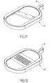
- the apparatus according to the invention is not necessarily used with a movable cutting tool 10 and a complementary cutting tool 11 fixed. Indeed, the apparatus according to the invention can be used with a single mobile cutting tool. So, the figure 11 illustrates a mobile cutting tool 10 'that can be used alone for producing thin slices while the figure 12 illustrates a movable cutting tool 10 "that can be used alone for grating food.It should be noted that when the cutting tool 10 ';10" mobile is used alone, the frequency of the reciprocating movements of the latter can be higher than when the movable cutting tool 10 is used in combination with the fixed complementary cutting tool 11.
- the apparatus may then comprise identification means 90 of the complementary cutting tool 11 that can be made in any appropriate manner.
- the identification means 90 may, for example, comprise on the one hand a magnet 91 integrated in the fixed complementary cutting tool, and on the other hand, a sensor
- the magnetic sensor 92 is, for example, a magnetic switch with a flexible blade called in English "reed switch” connected to a circuit powering the electric motor 38.
- the magnetic sensor 92 is closed so that the electric motor 38 is powered by a circuit 93 inducing a "slow" rotation speed.
- the magnetic sensor 92 is open so that the electric motor 38 is powered by a circuit 94 inducing a "fast” rotation speed greater than the rotation speed. "Slow"
- the motorized operating means 36 are adapted to modify their operating speed as a function of the identification of the complementary cutting tool 11.
- the identification means 90 of the complementary cutting tool 11 fixed can be used to prohibit the operation of motorized operating means 36 in the absence of the complementary cutting tool 11.
- the fixed complementary cutting tool 11 is not necessarily integral with the movable cutting tool 10.
- the frame 1 and / or the movable cutting tool 10 may be shaped to prevent coupling of the coupling member 35 of the movable cutting tool 10 with the drive member. 37 motorized operating means 36 in the absence of the complementary cutting tool 11 fixed.
- the movable cutting tool 10 and the complementary cutting tool 11 are not necessarily removable relative to the frame 1.
- the electric motor 38 is integrated in the trunk 2 permanently fitted to the cutting head 3.
- the electric motor 38 can also be integrated in the cover 6; the electric motor 38 can also be integrated in a housing removably adapted to the food cutting apparatus, in particular on the frame 1 or on the lid 6.
- the operating means 36 are not necessarily motorized.
- the operating means may then comprise for example a handle secured to the movable cutting tool.
- the food cutting device can also be associated with motorized operating means comprising a motorized housing independent of the frame and the lid, the food cutting device then forming an accessory used with the motorized housing.
- the main cutting edge 28 of the blade 25 preferably extends in a plane such as the cutting plane C, in particular to obtain cubes or rods, according to the complementary cutting tool 11 used. If desired, the main cutting edge 28 can be sharpened.
- the main cutting edge 28 is not necessarily straight.
- the main cutting edge 28 may in particular have a corrugated and / or micro-serrated leading edge, to facilitate the cutting of food without using sharpened cutting edge 28.
- the main cutting edge 28 of the blade 25 comprises corrugations 28 'and micro-serrations 28 ", the corrugations 28' create preferential zones of attack 28"'facilitating the initiation of cutting food.
- the length of each corrugation 28 ' is for example between 4 mm and 2 cm.
- the main cutting edge 28 may comprise between 5 and 20 micro-serrations 28" per cm, for example 10 micro-serrations. per cm.
- the mobile cutting tool 10 'capable of being used alone for the production of thin slices illustrated on FIG. figure 11 could include a blade 25 comprising a main cutting edge 28 having corrugations 28 'and / or micro-serrations 28 ".
Landscapes
- Life Sciences & Earth Sciences (AREA)
- Forests & Forestry (AREA)
- Engineering & Computer Science (AREA)
- Mechanical Engineering (AREA)
- Food-Manufacturing Devices (AREA)
- Processing Of Meat And Fish (AREA)
Applications Claiming Priority (2)
| Application Number | Priority Date | Filing Date | Title |
|---|---|---|---|
| FR1262573A FR2999901B1 (fr) | 2012-12-21 | 2012-12-21 | Appareil de decoupe d’aliments en tranches, batonnets,cubes ou filaments |
| EP13180117.7A EP2746003B1 (de) | 2012-12-21 | 2013-08-12 | Gerät zum Schneiden von Lebensmitteln in Scheiben, Stifte, Würfel oder Fäden |
Related Parent Applications (2)
| Application Number | Title | Priority Date | Filing Date |
|---|---|---|---|
| EP13180117.7A Division EP2746003B1 (de) | 2012-12-21 | 2013-08-12 | Gerät zum Schneiden von Lebensmitteln in Scheiben, Stifte, Würfel oder Fäden |
| EP13180117.7A Division-Into EP2746003B1 (de) | 2012-12-21 | 2013-08-12 | Gerät zum Schneiden von Lebensmitteln in Scheiben, Stifte, Würfel oder Fäden |
Publications (2)
| Publication Number | Publication Date |
|---|---|
| EP3034252A1 true EP3034252A1 (de) | 2016-06-22 |
| EP3034252B1 EP3034252B1 (de) | 2017-10-18 |
Family
ID=47902215
Family Applications (2)
| Application Number | Title | Priority Date | Filing Date |
|---|---|---|---|
| EP16153293.2A Active EP3034252B1 (de) | 2012-12-21 | 2013-08-12 | Gerät zum schneiden von lebensmitteln in scheiben, stifte, würfel oder sehr feine streifen |
| EP13180117.7A Active EP2746003B1 (de) | 2012-12-21 | 2013-08-12 | Gerät zum Schneiden von Lebensmitteln in Scheiben, Stifte, Würfel oder Fäden |
Family Applications After (1)
| Application Number | Title | Priority Date | Filing Date |
|---|---|---|---|
| EP13180117.7A Active EP2746003B1 (de) | 2012-12-21 | 2013-08-12 | Gerät zum Schneiden von Lebensmitteln in Scheiben, Stifte, Würfel oder Fäden |
Country Status (5)
| Country | Link |
|---|---|
| EP (2) | EP3034252B1 (de) |
| CN (2) | CN103878802B (de) |
| FR (1) | FR2999901B1 (de) |
| RU (1) | RU2654401C2 (de) |
| WO (1) | WO2014096711A1 (de) |
Families Citing this family (5)
| Publication number | Priority date | Publication date | Assignee | Title |
|---|---|---|---|---|
| WO2017205471A1 (en) | 2016-05-25 | 2017-11-30 | Sharkninja Operating Llc | Oscillating blade for food processor system |
| CN114147776A (zh) | 2018-08-10 | 2022-03-08 | 宁波金舜家居用品有限公司 | 一种食品切割器 |
| CN109910097B (zh) * | 2018-12-05 | 2020-11-06 | 宋少琦 | 一种蔬菜切割设备 |
| CN110625652B (zh) * | 2019-10-31 | 2021-07-13 | 湖南省原本记忆食品有限公司 | 一种食品加工用豆腐批量切块设备 |
| CN111493591B (zh) * | 2020-04-24 | 2021-10-15 | 高波 | 一种水果保鲜摆放展示装置 |
Citations (4)
| Publication number | Priority date | Publication date | Assignee | Title |
|---|---|---|---|---|
| CH277896A (de) * | 1949-12-02 | 1951-09-30 | Sigfrid Haell Ernst Otto | Maschine zum Schneiden von Hackfrüchten, Gemüse und dergleichen. |
| US5445332A (en) | 1993-09-02 | 1995-08-29 | Kabushiki Kaisha Izumi Seiki Seisakusho | Food processor |
| DE10060276A1 (de) * | 2000-12-05 | 2002-06-13 | Alexanderwerk Ag | Maschine zum Schneiden von Lebensmitteln, insbesondere von Käse |
| DE20319844U1 (de) * | 2003-12-22 | 2004-04-29 | Alexanderwerk Ag | Würfelgatter zum Schneiden von Lebensmitteln, insbesondere von Käse |
Family Cites Families (6)
| Publication number | Priority date | Publication date | Assignee | Title |
|---|---|---|---|---|
| SU1024047A1 (ru) * | 1981-03-04 | 1983-06-23 | Каспийское Производственно-Техническое Объединение "Касптехрыбпром" | Устройство дл резки пищевых продуктов |
| CH690323A5 (de) * | 1995-10-04 | 2000-07-31 | Ferag Ag | Verfahren und Vorrichtung zum Schneiden von kontinuierlich geforderten, flochigen Produkten insbesondere aus Papier. |
| DK172773B1 (da) * | 1996-02-22 | 1999-07-12 | Tetra Laval Food Hoyer As | Klippeanordning til klipning af især rørformede papirbaner |
| CH693263A5 (fr) * | 1999-06-18 | 2003-05-15 | Bobsts A | Procédé de découpage/refoulage d'éléments platsadjacents et dispositif pour sa mise en oeuvre. |
| KR100356599B1 (ko) * | 1999-06-21 | 2002-10-19 | 주식회사 빅섬 테크노 | 적재부 상, 하 연동형 식품슬라이서 |
| DE20319841U1 (de) * | 2003-12-22 | 2004-03-25 | Schmidt, Uwe | Vorrichtung zum Halten von Käseblöcken in Käseschneidemaschinen |
-
2012
- 2012-12-21 FR FR1262573A patent/FR2999901B1/fr active Active
-
2013
- 2013-08-12 EP EP16153293.2A patent/EP3034252B1/de active Active
- 2013-08-12 EP EP13180117.7A patent/EP2746003B1/de active Active
- 2013-12-18 CN CN201310696031.0A patent/CN103878802B/zh active Active
- 2013-12-18 CN CN201320835998.8U patent/CN203831455U/zh not_active Expired - Fee Related
- 2013-12-19 RU RU2015127758A patent/RU2654401C2/ru active
- 2013-12-19 WO PCT/FR2013/053181 patent/WO2014096711A1/fr not_active Ceased
Patent Citations (4)
| Publication number | Priority date | Publication date | Assignee | Title |
|---|---|---|---|---|
| CH277896A (de) * | 1949-12-02 | 1951-09-30 | Sigfrid Haell Ernst Otto | Maschine zum Schneiden von Hackfrüchten, Gemüse und dergleichen. |
| US5445332A (en) | 1993-09-02 | 1995-08-29 | Kabushiki Kaisha Izumi Seiki Seisakusho | Food processor |
| DE10060276A1 (de) * | 2000-12-05 | 2002-06-13 | Alexanderwerk Ag | Maschine zum Schneiden von Lebensmitteln, insbesondere von Käse |
| DE20319844U1 (de) * | 2003-12-22 | 2004-04-29 | Alexanderwerk Ag | Würfelgatter zum Schneiden von Lebensmitteln, insbesondere von Käse |
Also Published As
| Publication number | Publication date |
|---|---|
| CN103878802B (zh) | 2017-08-11 |
| EP2746003B1 (de) | 2016-03-30 |
| RU2015127758A (ru) | 2017-01-27 |
| EP2746003A1 (de) | 2014-06-25 |
| FR2999901B1 (fr) | 2014-12-26 |
| RU2654401C2 (ru) | 2018-05-17 |
| FR2999901A1 (fr) | 2014-06-27 |
| EP3034252B1 (de) | 2017-10-18 |
| CN203831455U (zh) | 2014-09-17 |
| CN103878802A (zh) | 2014-06-25 |
| WO2014096711A1 (fr) | 2014-06-26 |
Similar Documents
| Publication | Publication Date | Title |
|---|---|---|
| EP3181310B1 (de) | Gerät zum schneiden von lebensmitteln mit abwechselnden bewegungen mit herausnehmbarem, waschbarem behälter | |
| EP2746003B1 (de) | Gerät zum Schneiden von Lebensmitteln in Scheiben, Stifte, Würfel oder Fäden | |
| FR2857840A1 (fr) | Appareil de transformation d'aliments, notamment de jus ou centrifugeuse | |
| EP2062516A1 (de) | Manueller Gemüseschneider zum Schneiden des Gemüses in Stiftchen oder Würfel | |
| EP2941334B1 (de) | Vorrichtung zum schneiden von lebensmitteln mit kompaktem getriebe | |
| EP2934833B1 (de) | Vorrichtung zum schneiden von lebensmitteln mittels einer wechselbewegung ausgerüstet mit einer sicherheitssteuerung | |
| EP2856919A1 (de) | Zubehör zum Schneiden von Lebensmitteln, das mehrere Werkzeuge für den Nachschnitt umfasst | |
| EP3324802B1 (de) | Lebensmittelzubereitungsvorrichtung mit mindestens einem rotierenden spiralschneidwerkzeug | |
| EP0929383B1 (de) | Maschine zum auf genaues mass zerkleinern von nahrungsmitteln | |
| BE1024083B1 (fr) | Trancheuse de pain avec un moyen de pression et un organe de poussée | |
| EP2941161B1 (de) | Lebensmittelzubereitungsvorrichtung mit einer halterung zur anbringung eines abnehmbaren reinigungszubehörs | |
| EP2801455B1 (de) | Maschine zum automatischen Schneiden von Brot | |
| EP3967465B1 (de) | Brotschneidemaschine mit einer halterung für die brotscheiben | |
| EP2260984B1 (de) | Methode und Vorrichtung zum Schneiden von Brot | |
| EP3898138B1 (de) | Motorisierte küchenmaschine | |
| EP0014135B1 (de) | Vorrichtungen zum in Scheiben schneiden von Lachs | |
| EP0134802A1 (de) | Holzspaltgeräte, insbesondere für klötze. | |
| EP3169208B1 (de) | Umkehrbares rotierendes verarbeitungswerkzeug sowie lebensmittelzubereitungsvorrichtung mit umkehrbarem rotierenden verarbeitungswerkzeug | |
| BE882897A (fr) | Dispositif pour la coupe de produits alimentaires | |
| EP1621301A1 (de) | Vorrichtung zum automatischen Schneiden von Brot in Scheiben | |
| FR2535642A1 (fr) | Machine pour debiter en tranches un produit | |
| WO2002040232A1 (fr) | Machine pour le decoupage d'une piece de viande presentant un os a moelle | |
| CH299453A (fr) | Machine pour fendre les têtes de pièces présentant une tige, notamment de vis. |
Legal Events
| Date | Code | Title | Description |
|---|---|---|---|
| PUAI | Public reference made under article 153(3) epc to a published international application that has entered the european phase |
Free format text: ORIGINAL CODE: 0009012 |
|
| AC | Divisional application: reference to earlier application |
Ref document number: 2746003 Country of ref document: EP Kind code of ref document: P |
|
| AK | Designated contracting states |
Kind code of ref document: A1 Designated state(s): AL AT BE BG CH CY CZ DE DK EE ES FI FR GB GR HR HU IE IS IT LI LT LU LV MC MK MT NL NO PL PT RO RS SE SI SK SM TR |
|
| RAP1 | Party data changed (applicant data changed or rights of an application transferred) |
Owner name: SEB S.A. |
|
| 17P | Request for examination filed |
Effective date: 20161221 |
|
| RBV | Designated contracting states (corrected) |
Designated state(s): AL AT BE BG CH CY CZ DE DK EE ES FI FR GB GR HR HU IE IS IT LI LT LU LV MC MK MT NL NO PL PT RO RS SE SI SK SM TR |
|
| REG | Reference to a national code |
Ref country code: DE Ref legal event code: R079 Ref document number: 602013028273 Country of ref document: DE Free format text: PREVIOUS MAIN CLASS: B26D0001060000 Ipc: B26D0003200000 |
|
| GRAP | Despatch of communication of intention to grant a patent |
Free format text: ORIGINAL CODE: EPIDOSNIGR1 |
|
| RIC1 | Information provided on ipc code assigned before grant |
Ipc: B26D 7/00 20060101ALN20170412BHEP Ipc: B26D 3/20 20060101AFI20170412BHEP Ipc: B26D 1/06 20060101ALI20170412BHEP Ipc: B26D 7/06 20060101ALI20170412BHEP Ipc: B26D 1/00 20060101ALI20170412BHEP Ipc: B26D 3/18 20060101ALI20170412BHEP |
|
| INTG | Intention to grant announced |
Effective date: 20170502 |
|
| GRAS | Grant fee paid |
Free format text: ORIGINAL CODE: EPIDOSNIGR3 |
|
| GRAA | (expected) grant |
Free format text: ORIGINAL CODE: 0009210 |
|
| AC | Divisional application: reference to earlier application |
Ref document number: 2746003 Country of ref document: EP Kind code of ref document: P |
|
| AK | Designated contracting states |
Kind code of ref document: B1 Designated state(s): AL AT BE BG CH CY CZ DE DK EE ES FI FR GB GR HR HU IE IS IT LI LT LU LV MC MK MT NL NO PL PT RO RS SE SI SK SM TR |
|
| REG | Reference to a national code |
Ref country code: GB Ref legal event code: FG4D Free format text: NOT ENGLISH |
|
| RIN1 | Information on inventor provided before grant (corrected) |
Inventor name: VALLINO, VINCENT Inventor name: VOLATIER, SEBASTIEN Inventor name: CYPRES, REGIS Inventor name: PEDRICO, PASCAL |
|
| REG | Reference to a national code |
Ref country code: CH Ref legal event code: EP |
|
| REG | Reference to a national code |
Ref country code: AT Ref legal event code: REF Ref document number: 937539 Country of ref document: AT Kind code of ref document: T Effective date: 20171115 Ref country code: IE Ref legal event code: FG4D Free format text: LANGUAGE OF EP DOCUMENT: FRENCH |
|
| REG | Reference to a national code |
Ref country code: DE Ref legal event code: R096 Ref document number: 602013028273 Country of ref document: DE |
|
| REG | Reference to a national code |
Ref country code: NL Ref legal event code: MP Effective date: 20171018 |
|
| REG | Reference to a national code |
Ref country code: LT Ref legal event code: MG4D |
|
| REG | Reference to a national code |
Ref country code: AT Ref legal event code: MK05 Ref document number: 937539 Country of ref document: AT Kind code of ref document: T Effective date: 20171018 |
|
| PG25 | Lapsed in a contracting state [announced via postgrant information from national office to epo] |
Ref country code: NL Free format text: LAPSE BECAUSE OF FAILURE TO SUBMIT A TRANSLATION OF THE DESCRIPTION OR TO PAY THE FEE WITHIN THE PRESCRIBED TIME-LIMIT Effective date: 20171018 |
|
| PG25 | Lapsed in a contracting state [announced via postgrant information from national office to epo] |
Ref country code: ES Free format text: LAPSE BECAUSE OF FAILURE TO SUBMIT A TRANSLATION OF THE DESCRIPTION OR TO PAY THE FEE WITHIN THE PRESCRIBED TIME-LIMIT Effective date: 20171018 Ref country code: LT Free format text: LAPSE BECAUSE OF FAILURE TO SUBMIT A TRANSLATION OF THE DESCRIPTION OR TO PAY THE FEE WITHIN THE PRESCRIBED TIME-LIMIT Effective date: 20171018 Ref country code: FI Free format text: LAPSE BECAUSE OF FAILURE TO SUBMIT A TRANSLATION OF THE DESCRIPTION OR TO PAY THE FEE WITHIN THE PRESCRIBED TIME-LIMIT Effective date: 20171018 Ref country code: NO Free format text: LAPSE BECAUSE OF FAILURE TO SUBMIT A TRANSLATION OF THE DESCRIPTION OR TO PAY THE FEE WITHIN THE PRESCRIBED TIME-LIMIT Effective date: 20180118 Ref country code: SE Free format text: LAPSE BECAUSE OF FAILURE TO SUBMIT A TRANSLATION OF THE DESCRIPTION OR TO PAY THE FEE WITHIN THE PRESCRIBED TIME-LIMIT Effective date: 20171018 |
|
| PG25 | Lapsed in a contracting state [announced via postgrant information from national office to epo] |
Ref country code: LV Free format text: LAPSE BECAUSE OF FAILURE TO SUBMIT A TRANSLATION OF THE DESCRIPTION OR TO PAY THE FEE WITHIN THE PRESCRIBED TIME-LIMIT Effective date: 20171018 Ref country code: GR Free format text: LAPSE BECAUSE OF FAILURE TO SUBMIT A TRANSLATION OF THE DESCRIPTION OR TO PAY THE FEE WITHIN THE PRESCRIBED TIME-LIMIT Effective date: 20180119 Ref country code: AT Free format text: LAPSE BECAUSE OF FAILURE TO SUBMIT A TRANSLATION OF THE DESCRIPTION OR TO PAY THE FEE WITHIN THE PRESCRIBED TIME-LIMIT Effective date: 20171018 Ref country code: HR Free format text: LAPSE BECAUSE OF FAILURE TO SUBMIT A TRANSLATION OF THE DESCRIPTION OR TO PAY THE FEE WITHIN THE PRESCRIBED TIME-LIMIT Effective date: 20171018 Ref country code: IS Free format text: LAPSE BECAUSE OF FAILURE TO SUBMIT A TRANSLATION OF THE DESCRIPTION OR TO PAY THE FEE WITHIN THE PRESCRIBED TIME-LIMIT Effective date: 20180218 Ref country code: RS Free format text: LAPSE BECAUSE OF FAILURE TO SUBMIT A TRANSLATION OF THE DESCRIPTION OR TO PAY THE FEE WITHIN THE PRESCRIBED TIME-LIMIT Effective date: 20171018 Ref country code: BG Free format text: LAPSE BECAUSE OF FAILURE TO SUBMIT A TRANSLATION OF THE DESCRIPTION OR TO PAY THE FEE WITHIN THE PRESCRIBED TIME-LIMIT Effective date: 20180118 |
|
| REG | Reference to a national code |
Ref country code: DE Ref legal event code: R097 Ref document number: 602013028273 Country of ref document: DE |
|
| PG25 | Lapsed in a contracting state [announced via postgrant information from national office to epo] |
Ref country code: EE Free format text: LAPSE BECAUSE OF FAILURE TO SUBMIT A TRANSLATION OF THE DESCRIPTION OR TO PAY THE FEE WITHIN THE PRESCRIBED TIME-LIMIT Effective date: 20171018 Ref country code: DK Free format text: LAPSE BECAUSE OF FAILURE TO SUBMIT A TRANSLATION OF THE DESCRIPTION OR TO PAY THE FEE WITHIN THE PRESCRIBED TIME-LIMIT Effective date: 20171018 Ref country code: SK Free format text: LAPSE BECAUSE OF FAILURE TO SUBMIT A TRANSLATION OF THE DESCRIPTION OR TO PAY THE FEE WITHIN THE PRESCRIBED TIME-LIMIT Effective date: 20171018 Ref country code: CZ Free format text: LAPSE BECAUSE OF FAILURE TO SUBMIT A TRANSLATION OF THE DESCRIPTION OR TO PAY THE FEE WITHIN THE PRESCRIBED TIME-LIMIT Effective date: 20171018 |
|
| PLBE | No opposition filed within time limit |
Free format text: ORIGINAL CODE: 0009261 |
|
| STAA | Information on the status of an ep patent application or granted ep patent |
Free format text: STATUS: NO OPPOSITION FILED WITHIN TIME LIMIT |
|
| REG | Reference to a national code |
Ref country code: FR Ref legal event code: PLFP Year of fee payment: 6 |
|
| PG25 | Lapsed in a contracting state [announced via postgrant information from national office to epo] |
Ref country code: SM Free format text: LAPSE BECAUSE OF FAILURE TO SUBMIT A TRANSLATION OF THE DESCRIPTION OR TO PAY THE FEE WITHIN THE PRESCRIBED TIME-LIMIT Effective date: 20171018 Ref country code: PL Free format text: LAPSE BECAUSE OF FAILURE TO SUBMIT A TRANSLATION OF THE DESCRIPTION OR TO PAY THE FEE WITHIN THE PRESCRIBED TIME-LIMIT Effective date: 20171018 Ref country code: IT Free format text: LAPSE BECAUSE OF FAILURE TO SUBMIT A TRANSLATION OF THE DESCRIPTION OR TO PAY THE FEE WITHIN THE PRESCRIBED TIME-LIMIT Effective date: 20171018 Ref country code: RO Free format text: LAPSE BECAUSE OF FAILURE TO SUBMIT A TRANSLATION OF THE DESCRIPTION OR TO PAY THE FEE WITHIN THE PRESCRIBED TIME-LIMIT Effective date: 20171018 |
|
| 26N | No opposition filed |
Effective date: 20180719 |
|
| PG25 | Lapsed in a contracting state [announced via postgrant information from national office to epo] |
Ref country code: MT Free format text: LAPSE BECAUSE OF FAILURE TO SUBMIT A TRANSLATION OF THE DESCRIPTION OR TO PAY THE FEE WITHIN THE PRESCRIBED TIME-LIMIT Effective date: 20171018 |
|
| PG25 | Lapsed in a contracting state [announced via postgrant information from national office to epo] |
Ref country code: SI Free format text: LAPSE BECAUSE OF FAILURE TO SUBMIT A TRANSLATION OF THE DESCRIPTION OR TO PAY THE FEE WITHIN THE PRESCRIBED TIME-LIMIT Effective date: 20171018 |
|
| PG25 | Lapsed in a contracting state [announced via postgrant information from national office to epo] |
Ref country code: MC Free format text: LAPSE BECAUSE OF FAILURE TO SUBMIT A TRANSLATION OF THE DESCRIPTION OR TO PAY THE FEE WITHIN THE PRESCRIBED TIME-LIMIT Effective date: 20171018 |
|
| REG | Reference to a national code |
Ref country code: CH Ref legal event code: PL |
|
| PG25 | Lapsed in a contracting state [announced via postgrant information from national office to epo] |
Ref country code: LI Free format text: LAPSE BECAUSE OF NON-PAYMENT OF DUE FEES Effective date: 20180831 Ref country code: LU Free format text: LAPSE BECAUSE OF NON-PAYMENT OF DUE FEES Effective date: 20180812 Ref country code: CH Free format text: LAPSE BECAUSE OF NON-PAYMENT OF DUE FEES Effective date: 20180831 |
|
| REG | Reference to a national code |
Ref country code: BE Ref legal event code: MM Effective date: 20180831 |
|
| REG | Reference to a national code |
Ref country code: IE Ref legal event code: MM4A |
|
| PG25 | Lapsed in a contracting state [announced via postgrant information from national office to epo] |
Ref country code: IE Free format text: LAPSE BECAUSE OF NON-PAYMENT OF DUE FEES Effective date: 20180812 |
|
| PG25 | Lapsed in a contracting state [announced via postgrant information from national office to epo] |
Ref country code: BE Free format text: LAPSE BECAUSE OF NON-PAYMENT OF DUE FEES Effective date: 20180831 |
|
| PG25 | Lapsed in a contracting state [announced via postgrant information from national office to epo] |
Ref country code: TR Free format text: LAPSE BECAUSE OF FAILURE TO SUBMIT A TRANSLATION OF THE DESCRIPTION OR TO PAY THE FEE WITHIN THE PRESCRIBED TIME-LIMIT Effective date: 20171018 |
|
| PG25 | Lapsed in a contracting state [announced via postgrant information from national office to epo] |
Ref country code: PT Free format text: LAPSE BECAUSE OF FAILURE TO SUBMIT A TRANSLATION OF THE DESCRIPTION OR TO PAY THE FEE WITHIN THE PRESCRIBED TIME-LIMIT Effective date: 20171018 |
|
| PG25 | Lapsed in a contracting state [announced via postgrant information from national office to epo] |
Ref country code: MK Free format text: LAPSE BECAUSE OF NON-PAYMENT OF DUE FEES Effective date: 20171018 Ref country code: CY Free format text: LAPSE BECAUSE OF FAILURE TO SUBMIT A TRANSLATION OF THE DESCRIPTION OR TO PAY THE FEE WITHIN THE PRESCRIBED TIME-LIMIT Effective date: 20171018 Ref country code: HU Free format text: LAPSE BECAUSE OF FAILURE TO SUBMIT A TRANSLATION OF THE DESCRIPTION OR TO PAY THE FEE WITHIN THE PRESCRIBED TIME-LIMIT; INVALID AB INITIO Effective date: 20130812 |
|
| PG25 | Lapsed in a contracting state [announced via postgrant information from national office to epo] |
Ref country code: AL Free format text: LAPSE BECAUSE OF FAILURE TO SUBMIT A TRANSLATION OF THE DESCRIPTION OR TO PAY THE FEE WITHIN THE PRESCRIBED TIME-LIMIT Effective date: 20171018 |
|
| PGFP | Annual fee paid to national office [announced via postgrant information from national office to epo] |
Ref country code: GB Payment date: 20210819 Year of fee payment: 9 |
|
| GBPC | Gb: european patent ceased through non-payment of renewal fee |
Effective date: 20220812 |
|
| P01 | Opt-out of the competence of the unified patent court (upc) registered |
Effective date: 20230517 |
|
| PG25 | Lapsed in a contracting state [announced via postgrant information from national office to epo] |
Ref country code: GB Free format text: LAPSE BECAUSE OF NON-PAYMENT OF DUE FEES Effective date: 20220812 |
|
| PGFP | Annual fee paid to national office [announced via postgrant information from national office to epo] |
Ref country code: DE Payment date: 20250812 Year of fee payment: 13 |
|
| PGFP | Annual fee paid to national office [announced via postgrant information from national office to epo] |
Ref country code: FR Payment date: 20250828 Year of fee payment: 13 |