EP3034376B1 - Transportanordnung für zerlegbare schubkarren - Google Patents
Transportanordnung für zerlegbare schubkarren Download PDFInfo
- Publication number
- EP3034376B1 EP3034376B1 EP15197382.3A EP15197382A EP3034376B1 EP 3034376 B1 EP3034376 B1 EP 3034376B1 EP 15197382 A EP15197382 A EP 15197382A EP 3034376 B1 EP3034376 B1 EP 3034376B1
- Authority
- EP
- European Patent Office
- Prior art keywords
- wheelbarrow
- wall
- frame
- assembly according
- holding box
- Prior art date
- Legal status (The legal status is an assumption and is not a legal conclusion. Google has not performed a legal analysis and makes no representation as to the accuracy of the status listed.)
- Active
Links
Images




Classifications
-
- B—PERFORMING OPERATIONS; TRANSPORTING
- B62—LAND VEHICLES FOR TRAVELLING OTHERWISE THAN ON RAILS
- B62B—HAND-PROPELLED VEHICLES, e.g. HAND CARTS OR PERAMBULATORS; SLEDGES
- B62B1/00—Hand carts having only one axis carrying one or more transport wheels; Equipment therefor
- B62B1/18—Hand carts having only one axis carrying one or more transport wheels; Equipment therefor in which the load is disposed between the wheel axis and the handles, e.g. wheelbarrows
- B62B1/20—Hand carts having only one axis carrying one or more transport wheels; Equipment therefor in which the load is disposed between the wheel axis and the handles, e.g. wheelbarrows involving parts being collapsible, attachable, detachable or convertible
- B62B1/206—Hand carts having only one axis carrying one or more transport wheels; Equipment therefor in which the load is disposed between the wheel axis and the handles, e.g. wheelbarrows involving parts being collapsible, attachable, detachable or convertible and capable of being completely disassembled
-
- B—PERFORMING OPERATIONS; TRANSPORTING
- B65—CONVEYING; PACKING; STORING; HANDLING THIN OR FILAMENTARY MATERIAL
- B65D—CONTAINERS FOR STORAGE OR TRANSPORT OF ARTICLES OR MATERIALS, e.g. BAGS, BARRELS, BOTTLES, BOXES, CANS, CARTONS, CRATES, DRUMS, JARS, TANKS, HOPPERS, FORWARDING CONTAINERS; ACCESSORIES, CLOSURES, OR FITTINGS THEREFOR; PACKAGING ELEMENTS; PACKAGES
- B65D85/00—Containers, packaging elements or packages, specially adapted for particular articles or materials
- B65D85/68—Containers, packaging elements or packages, specially adapted for particular articles or materials for machines, engines or vehicles in assembled or dismantled form
-
- B—PERFORMING OPERATIONS; TRANSPORTING
- B65—CONVEYING; PACKING; STORING; HANDLING THIN OR FILAMENTARY MATERIAL
- B65D—CONTAINERS FOR STORAGE OR TRANSPORT OF ARTICLES OR MATERIALS, e.g. BAGS, BARRELS, BOTTLES, BOXES, CANS, CARTONS, CRATES, DRUMS, JARS, TANKS, HOPPERS, FORWARDING CONTAINERS; ACCESSORIES, CLOSURES, OR FITTINGS THEREFOR; PACKAGING ELEMENTS; PACKAGES
- B65D2585/00—Containers, packaging elements or packages specially adapted for particular articles or materials
- B65D2585/68—Containers, packaging elements or packages specially adapted for particular articles or materials for machines, engines, or vehicles in assembled or dismantled form
- B65D2585/6802—Containers, packaging elements or packages specially adapted for particular articles or materials for machines, engines, or vehicles in assembled or dismantled form specific machines, engines or vehicles
- B65D2585/6897—Containers, packaging elements or packages specially adapted for particular articles or materials for machines, engines, or vehicles in assembled or dismantled form specific machines, engines or vehicles others
Definitions
- the invention relates to the technical field of wheelbarrows, and more particularly to the logistics of such stretcher vehicles.
- Wheelbarrows are conventionally delivered stacked on pallets.
- the document FR 2717761 proposes a wheelbarrow stackable by pre-assembled sub-elements, the wheelbarrow comprising two sets: a first assembly formed by the body and the stretchers, and a second assembly formed by the feet and wheel bearings, these two assemblies being connected together in a manner that can be dismantled by a wheel with a removable axle.
- the stretchers are made by a single tube.
- the feet are also formed by a folded one-piece tube.
- the second set is positioned in the box and the wheel is placed between the stretchers. This arrangement allows stacking for storage, the box and the stretchers of a wheelbarrow being placed above the body and the stretcher of a lower wheelbarrow.
- the document FR 2767106 proposes a wheelbarrow of the same general type as described in the document FR 2717761 , the assembly of the first and the second assembly can be performed without the aid of tools, by clipping.
- a first object of the invention is to provide a logistics for dismountable wheelbarrows, to provide a wide range of wheelbarrows, advantageously to the unit, to a variety of end customers.
- a second object of the invention is to provide such a logistics which ensures a high quality of service, in particular a high quality perceived by the end customers.
- a third object of the invention is to provide such a logistics that provides security during transport, especially in case of stacking and palletizing.
- a fourth object of the invention is to provide such a logistics that facilitates, for the first user of a dismountable wheelbarrow, an intuitive assembly, without significant recourse to reasoning or previous experience.
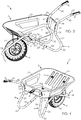
- the Figures 1 and 2 represent a wheelbarrow 1 in an exploded configuration according to two different orientations.
- the wheelbarrow 1 comprises a tank 2 , a frame comprising a stopper 3 and two stretchers 4 , two body supports 5 for taking up forces from the tank 2 on the stopper 3, two buffers 6 making it possible to interface the vat 2 and the stretchers 4, a wheel 7 and two handles 8 adapted to cooperate with the shafts 4 to facilitate the gripping and the operation of the wheelbarrow 1 for a user.
- the elements of the wheelbarrow 1 are provided with holes that allow the assembly of the wheelbarrow 1.
- the holes of the various elements will be referenced Xa, where "X” is the reference of the element carrying the piercing and "a” is the index defining that it is a piercing.
- the tank 2 has a bottom 9 , a rear border 10 , a front edge 11 and two lateral edges 12 each connecting the rear edge 10 to the front edge 11 .
- the borders 10 , 11 , 12 form a belt that protrudes from the bottom 9 and are inclined relative to the bottom 9 so that the tank 2 has a flared shape from the bottom 9.
- the end rim of the borders 10, 11, 12, opposite the bottom 9, is folded in order to avoid any injury to the user during the manipulation of the tank 2.
- the rim 11 before the rear edge 10 and the bottom 9 of the vessel 2 are provided with holes 11a, 10a, 9a to allow assembly of the wheelbarrow 1 as will be explained below.
- edges 10, 11, 12 may have embossed for stiffening or simply aesthetic purposes.
- Bumper 3 is a generally V-shaped bent tube having a base and two arms whose ends are bent.
- the stopper 3 comprises successively a first portion 13, a first fold 14, a second portion 15, a second fold 16, a third portion 17, a third fold 18, a fourth portion 19, a fourth fold 20, a fifth portion 21, a fifth fold 22 and a sixth portion 23.
- the third fold 18 forms the base of the V and the first portion 13, the second portion 15, the third portion 17, the first fold 14 and the second fold 16, on the one hand, and the fourth portion 19 , the fifth portion 21, the sixth portion 23, the fourth fold 20 and the fifth fold 22, on the other hand, form respectively the first arm and the second arm of V.
- the third portion 17 and the fourth portion 19 extend in the same plane different from one plane in which the first portion 13 , the second portion 15 , the fifth portion 21 and the sixth portion 23 extend, the second fold 16 and the fourth fold 20 forming the angular offset between these two extensions.
- first portion 13 and the second portion 15 are angularly offset by the first fold 14, as well as the sixth portion 23 and the fifth portion 21 are angularly offset by the fifth fold 22 .
- the first portion 13 and the sixth portion 23 are provided with holes 13a , 23a to allow the assembly of the shafts 4 as we shall see below.
- the third portion 17 and the fourth portion 19 are also provided with holes 17a , 19a to allow the fastening of the stopper 3 and the supports 5 of cash.
- the stopper 3 also comprises a crosspiece 24 provided with holes 24a , connecting the second fold 16 and the fourth fold 20 , and two lugs 25 also provided with holes 25a , the first lug 25 being integral with the third portion 17 , the second lug 25 being integral with the fourth portion 19 .
- the stretchers 4 are curved tubes having a general S shape.
- the two stretchers 4 are identical, so we will describe only one stretcher 4.
- the stretcher 4 comprises successively a first section 26 , a first elbow 27 , a second section 28 , a second elbow 29 , a third section 30, a third elbow 31 , a fourth section 32 , a fourth elbow 33 , a fifth section 34 and finally, a restriction 35 , the restriction 35 having a diameter smaller than the diameter of the remainder of the stretcher 4.
- the tubes used to form the stopper 3 and the shafts 4 are identical and the outer diameter of the restriction 35 is equal to an inner diameter of the remainder of the stretcher tube 4 so as to allow the interlocking of the restriction 35 stretchers 4 in the first portion 13 and the sixth portion 23 of the stopper 3.
- the first bend 27, the second bend 29 and the third bend 31 open in a substantially similar direction so as to form a first curve of the S, the fourth bend 33 opening in an opposite direction so as to form the bend. other curve of S.
- the restriction 35 comprises holes 35a able to come opposite the holes 13a, 23a of the first portion 13 and the sixth portion 23 of the stopper 3 to allow the assembly of the shafts 4 with the stopper 3, and the third section 30 includes bores 30 is to allow the fastening of the tank 2 with the shafts 4.
- the body supports 5 are identical, so we will describe only one support 5 cash.
- the body support 5 is a substantially U-shaped metal part having a body 36 and two ends 37, 38, namely a first end 37 and a second end 38, bent with respect to the body 36, the ends 37, 38 extending by flaring away from the body 36.
- the body 36 has a general shape of gutter that is to say that it is rounded, and the ends 37, 38 are substantially planar and each comprise a bore 37a, 38a.
- Buffers 6 are also identical, so we will describe only one buffer 6.
- the pad 6 comprises a base 39 of complementary shape to the part of the tank 2 against which the pad 6 is in contact, that is to say a base 39 substantially flat if the pad 6 is in contact with a flat surface of the tank 2 or a concave base 39 if the pad 6 is in contact with a convex surface of the tank 2.
- the pad 6 Opposite the base 39, the pad 6 comprises a concave face 40 adapted to receive a section of a stretcher 4, in the illustrated example, the third section 30.
- the buffer 6 comprises two holes 6a passing from the concave face 40.
- the wheel 7 comprises a rim 41, a hub 42 which is traversed by an axis (not shown) to allow the rotation of the wheel 7, and a tire 43 mounted on the rim 41.
- the wheel 7 is of the air chamber type and comprises a valve protruding from the rim 41.
- the presence of the air chamber makes it possible to adjust the pressure in the wheel 7 so as to make it possible to increase the connection surface between the wheel 7 and the ground and thus allow a better distribution of the load of the wheelbarrow 1 on the ground or, conversely, reduce the contact area between the wheel 7 and the ground and make the wheelbarrow 1 easily maneuverable for the user .
- the wheel 7 is full, that is to say that the tire is made in an elastomeric strip.
- handles 8 are in the form of blind sleeves and have alternating depressions and bumps to allow the gripping and maintaining the wheelbarrow 1 by a user.
- the handles 8 have an internal diameter slightly smaller than the external diameter of the tubes of the shafts 4 so as to ensure a good hold of the handles 8 on the shafts 4.
- the assembly of the wheelbarrow 1 by a user is done by means of screws and nuts not shown, according to the following steps.
- the user forms the frame by assembling the shafts 4 on the stopper 3. For this, the user inserts the restriction 35 of each stretcher 4 into the first portion 13 or the sixth portion 23 of the stopper 3 so that the bores 35a of the restrictions 35 are opposite the bores 13a, 23a of the first portion 13 and the sixth portion 23.
- the user mounts the wheel 7 on the chassis.
- the user positions the hub of the wheel 7 opposite the holes 25a of the tabs 25 of the stopper 3, inserts the axis (not shown) so that the axis passes through the wheel 7 and the tabs 25, then solidarizes all by means of nuts.
- the assembled portion of the wheelbarrow 1, that is to say the frame and the wheel 7, is stable and rests on three points, namely the fourth bend 33 of the stretchers 4 and the wheel 7 .
- the user can then secure the tank 2 to the frame by means of screws and nuts.
- the user positions the 5 fund supports so that the bore 37a of the first end 37 of the box 5 of supports is opposite a bore 11a of the rim 11 before the vessel 2, and the bore 38a of the second end 38 of the box 5 of supports is opposite a bore 17a, 19a of the third portion 17 or the fourth portion 19 of the bumper 3.
- the user can then secure the box supports 5 to the stopper 3 and to the tank 2 by means of screws and nuts.
- the user can then complete the assembly of the wheelbarrow 1 during a fifth step in which the handles 8 are secured to the shafts 4.
- the user places the handles 8 for a few minutes in hot water between 75 ° C and 85 ° C, and preferably 80 ° C, to expand and soften the handles 8 to make them malleable.
- the user can grip the handles 8 on the first section 26 of each of the stretchers 4.
- the handles 8 cover their initial dimensions and are secured to the shafts 4.
- the handles 8 are fitted during manufacture on the stretchers 4.
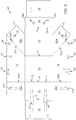
- hinge line will be used to designate one or more lines of creasing, grooving, one or more lines of weakness, for example by making notches or perforations, allowing the pivoting the elements of the blank 49 relative to each other.
- the holding blank 49 has a symmetry with respect to a longitudinal plane, with the exception of the detail structure of the passage openings of the stretchers.
- the holding blank 49 comprises a bottom wall 50, the other elements of the blank 49 being hinged, directly or indirectly, to this bottom wall 50.
- the bottom wall 50 is in abutment against the bottom 9 of the tank 2.
- the bottom wall 50 is of smaller or substantially equal dimensions to the dimensions of the bottom 9 of the tank 2, allowing support on the entire bottom 9 of the tank 2.
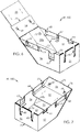
- the bottom wall 50 is intended to form the bottom of a holding box 100 of all the parts of a dismountable wheelbarrow as shown in FIG. Figures 1 to 4 the holding box 100 accommodating all the parts of the wheelbarrow 1.
- the holding box 100 is placed in the tank 2 and the tank assembly 2 / holding box 100 is housed in a transport carton 200.
- the holding box 100 comprises a bottom, formed by the bottom wall 50, and a side wall forming a belt substantially perpendicular to the bottom wall 50, and has no cover. In other embodiments, not shown, the holding box 100 has a cover, articulated or reported.
- the width of the bottom wall 50 is advantageously substantially equal to the width of the wheel 7, this arrangement contributing to the stability of the position of the wheel 7 in the holding box 100.
- the retaining blank 49 comprises, in its principal longitudinal elongation direction, a first rear flap 51 and a second rear flap 52, a first front flap 53, a second front flap 54, and a separation flap 55.
- the first rear flap 51 and the first front flap 53 are articulated transversely to the bottom wall 50 and are of the same width as the bottom wall 50.
- the second rear flap 52 is hinged transversely at the front and rear flap 51 is to be folded in 180 ° opposite the first rear flap 51 inwardly of the retaining box 100, when the volume setting of the sidewall 49 .
- the second front flap 54 is articulated transversely to the first front flap 53 and is intended to be folded at 180 ° with respect to the first front flap 53, towards the inside of the holding box 100, during the setting up of the flank 49.
- the blank 49 comprises two trapezoidal-shaped side flaps 56, 57 articulated longitudinally to the bottom wall 50 over the entire length of the bottom wall 50.
- the length of the lateral flaps 56, 57 is increasing from their hinge line at the bottom wall 50 to their free edge.
- the right side flap 56 is articulated transversely to a rear leg 58a and is articulated to a front leg 59a.
- the left side flap 57 is articulated transversely to a rear leg 58b and a front leg 59b.
- the blank 49 comprises means of passage, support and wedging of the elements of the wheelbarrow 1, and more precisely the bumper 3 and the stretchers 4.
- two oblong 60.61 lumens extend longitudinally on either side of the transverse hinge line of the first rear flap 51 to the second rear flap 52.
- the tabs 58a, 58b are placed between the first rear flap 51 and the second rear flap 52, and the cutouts 62a, 62b come opposite the oblong slots 60, 61, the triple thickness of material forming the blank 49 ensuring a high mechanical strength for the wedging of the stopper 3 in the holding box 100.
- the right lateral flap 56 comprises means of positioning, passage and setting 63, 64, 65 of a first stretcher, these means 63, 64, 65 extending from the longitudinal free edge of this right lateral flap 56.
- the left side door 57 comprises positioning means, passage and wedging 66, 67, 68 of the second stretcher, these means 66, 67, 68 extending from the longitudinal free edge of the left side door.
- the positioning, passage and wedging means 63-65 disposed on the right lateral flap 56 are of similar design but of different dimensions from those of the positioning, passage and wedging means. 66-68 arranged on the left side shutter 57. These differences in dimensions apart, the blank 49 has a symmetry with respect to a longitudinal plane.
- this maintenance volume is provided without the use of additional material to that of the blank 49, by means of three sets of tabs and notches.
- the second rear flap 52 comprises, on its free transverse edge, two tabs 71 which are housed, when the volume of the blank 49 is set, in two notches 72 formed on the bottom wall 50 , near the hinge line with the first rear flap 51.
- the front tabs 59a, 59b are each provided, on their free edge, with a tongue 73 which is housed, when the volume of the blank 49 is set, in a notch 74 formed on the hinge line between the first front flap 53 and second flap 54 front.
- the second front flap 54 is provided with a tongue 54a, 54b on each of its two side edges, two tabs 54a, 54b being received in a respective recess 56a, 56b formed in the right side door 56 and the left side door 57, near the hinge line with the front leg 59a, 59b.
- the assembly formed by the first rear flap 51, the second rear flap 52 and the rear legs 58a, 58b is folded around the lines joints 75, 76, 82a, 82b so that the rear legs 58a, 58b are placed between the first rear flap 51 and the second rear flap 52, the lights 62a, 62b coming opposite the oblong slots 60,61 .
- the lateral flaps 56, 57 are folded at 90 ° with respect to the bottom wall 50 and the front lugs 59a, 59b are bent at 90 ° with respect to the lateral flaps 56, 57, around lines 83a, 83b of articulation, and then placed above the first front flap 53, the second front flap 54 is then folded 180 ° and placed opposite the tabs 59a, 59b inwardly of the holding box 100. in this arrangement , the cutouts 69, 70 are facing each other.
- the holding box 100 has an inclined front part, via a line 77 of articulation, and not perpendicular to the bottom wall 50.
- the angle of inclination of this front part of the box 100 is advantageously substantially equal to the angle between the front edge 11 and the bottom 9 of the tank 2.
- the means 63, 64, 65, 66, 67, 68 are provided with slots in their bottom, with a ventail, and, at their side edges, flaps to allow, as it will be explained below, the setting of the stretchers 4.
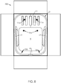
- the stopper 3 After placing the holding box 100 in the tank 3 ( figure 9 ), the stopper 3 is placed in the box 100, so that the stopper 3 passes through and bears against the base of the slots ( 60, 61, 62a, 62b ) formed in the triple thickness of blank 49. This setting in place leads to a provision of the type represented in figure 10 .
- the transverse dimension of the box 100 is advantageously of the order of the diameter of the wheel 7, allowing, taking advantage of the stiffness of the material forming the blank 49 , a blockage transverse wheel 7 in the holding box 100.
- This implementation leads to a provision of the type shown in FIG. figure 11 .
- a first stretcher 4 is placed in support in the means 64, 65 of positioning, passage and wedging, formed in the right side door 56 , the stretcher being also placed in support in the means 66 of positioning, passage and setting, arranged in the left side panel.
- This implementation leads to a disposition of the type represented in figure 12 .
- the separating flap 55 is then placed above the stretcher and the body supports 5 are advantageously placed against this separating flap 55, for example by means of blanks.
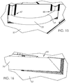
- This implementation leads to a disposition of the type represented in figure 13 .
- the second stretcher 4 is placed in abutment in the positioning means 67, 68 , passage and wedging, formed in the left side door 57, the stretcher being also placed in abutment in the means 63 for positioning, passage and setting, arranged in the right-hand side panel 56.
- This installation leads to a layout of the type represented in figure 14 .
- the transport carton 200 can then be closed again.
- the pads 6 and the screws and nuts, necessary for the assembly of the wheelbarrow 2 are placed in a bag which is slid under the wheel 7 after placing it in the holding box 100.
- the assembly as just described has many advantages.
- This set allows logistics for dismountable wheelbarrows, for providing a wide range of wheelbarrows, advantageously to the unit, to a variety of end customers.
- the customers can advantageously choose themselves the characteristics of the wheelbarrow desired, for example by connecting, via a computer, a tablet, or a mobile communication terminal, on an online command platform on the internet.
- This set ensures, for such logistics, a high quality of service, in particular a high quality perceived by the end customers.
- the positioning and setting means ensure that the parts of the wheelbarrow can not substantially move during transport, even in case of stacking and palletizing.
- This assembly finally makes it easier for the first user of a dismountable wheelbarrow, an intuitive assembly, without significant recourse to reasoning or previous experience. Indeed, the user discovers, during delivery, the parts in a defined order, which is advantageously presented in the assembly instructions.
Landscapes
- Engineering & Computer Science (AREA)
- Mechanical Engineering (AREA)
- Chemical & Material Sciences (AREA)
- Combustion & Propulsion (AREA)
- Transportation (AREA)
- Handcart (AREA)
Claims (10)
- Anordnung, umfassend:- eine Schubkarre (1) in Einzelteilen, umfassend:dadurch gekennzeichnet, dass die Anordnung umfasst:- eine Wanne (2);- ein Gestell, das geeignet ist, die Wanne (2) aufzunehmen;- ein Rad (7), das geeignet ist, drehbar auf dem Gestell montiert zu werden;- zwei Längsträger (4), die geeignet sind, auf dem Gestell befestigt zu werden, um Mittel zum Ergreifen und Betätigen der Schubkarre (1) zu bilden, und- einen Transportkarton (200), der geeignet ist, die Wanne (2) der Schubkarre (1) aufzunehmen, und- eine Halteschachtel (100) mit einer im Wesentlichen zur Wanne (2) komplementären Form, wobei diese Halteschachtel (100) in der Wanne (2) angeordnet und geeignet ist, das Gestell, die Längsträger (4) und das Rad (7) der Schubkarre (1) aufzunehmen.
- Anordnung nach Anspruch 1, dadurch gekennzeichnet, dass die Halteschachtel (100) einen Boden, eine erste Wand, eine zweite Wand, eine dritte Wand und eine vierte Wand umfasst, wobei diese vier Wände einen Gürtel bilden, der den Boden umschließt.
- Anordnung nach dem vorhergehenden Anspruch, dadurch gekennzeichnet, dass die erste Wand eine volle Fläche umfasst, die geeignet ist, ein erstes Ende des Gestells der Schubkarre abgestützt aufzunehmen.
- Anordnung nach Anspruch 3, dadurch gekennzeichnet, dass die zweite Wand, die der ersten gegenüberliegt, Öffnungen umfasst, die geeignet sind, zumindest teilweise ein zweites Ende des Gestells der Schubkarre, das dem ersten Ende gegenüberliegt, aufzunehmen.
- Anordnung nach einem der Ansprüche 2 bis 4, dadurch gekennzeichnet, dass die erste Wand Öffnungen umfasst, die geeignet sind, zumindest teilweise ein erstes Ende jedes der Längsträger der Schubkarre aufzunehmen.
- Anordnung nach einem der Ansprüche 2 bis 5, dadurch gekennzeichnet, dass die dritte Wand und die vierte Wand jeweils mit drei Schlitzen versehen sind, die am oberen Rand, der zum Boden der Halteschachtel (100) beabstandet ist, vorgesehen sind, wobei diese Schlitze geeignet sind, die zwei Längsträger (4) aufzunehmen.
- Anordnung nach dem vorhergehenden Anspruch, dadurch gekennzeichnet, dass die Schlitze mit einem zum Inneren des Kartons faltbaren Flügel versehen sind, um als Stütze für die Längsträger zu dienen.
- Anordnung nach Anspruch 6 oder Anspruch 7, dadurch gekennzeichnet, dass jeder Schlitz mit Klappen versehen ist, die sich auf einer geringeren Höhe als die Höhe des Schlitzes erstrecken, um eine Aufnahme zu definieren, in der der Längsträger aufgenommen wird, wobei es die Klappen ferner ermöglichen, den Längsträger in dem Schlitz zu halten.
- Anordnung nach einem der Ansprüche 6 bis 8, dadurch gekennzeichnet, dass jeder Schlitz eine eigene Höhe unabhängig von der Höhe der anderen Schlitze aufweist.
- Verfahren zum Zusammenbau der Anordnung nach einem der vorhergehenden Ansprüche, wobei dieses Verfahren die folgenden Schritte umfasst, darin bestehend:- den Transportkarton auszustellen;- die Halteschachtel (100) aufzustellen;- die Wanne (2) der Schubkarre (1) in dem Transportkarton (200) anzuordnen;- die Halteschachtel (100) in der Wanne (2) anzuordnen;- das Gestell der Schubkarre in der Halteschachtel (100) anzuordnen;- das Rad (7) auf dem Gestell der Schubkarre anzuordnen;- einen ersten Längsträger über dem Rad (7) anzuordnen, und- den zweiten Längsträger auf dem ersten Längsträger anzuordnen.
Applications Claiming Priority (1)
| Application Number | Priority Date | Filing Date | Title |
|---|---|---|---|
| FR1462514A FR3029880B1 (fr) | 2014-12-16 | 2014-12-16 | Ensemble de transport de brouettes demontables |
Publications (2)
| Publication Number | Publication Date |
|---|---|
| EP3034376A1 EP3034376A1 (de) | 2016-06-22 |
| EP3034376B1 true EP3034376B1 (de) | 2018-04-18 |
Family
ID=52737246
Family Applications (1)
| Application Number | Title | Priority Date | Filing Date |
|---|---|---|---|
| EP15197382.3A Active EP3034376B1 (de) | 2014-12-16 | 2015-12-01 | Transportanordnung für zerlegbare schubkarren |
Country Status (2)
| Country | Link |
|---|---|
| EP (1) | EP3034376B1 (de) |
| FR (1) | FR3029880B1 (de) |
Families Citing this family (4)
| Publication number | Priority date | Publication date | Assignee | Title |
|---|---|---|---|---|
| GB2555069A (en) * | 2016-03-31 | 2018-04-25 | Haemmerlin Ltd | Wheelbarrow |
| CN107187468B (zh) * | 2017-06-07 | 2019-05-03 | 江西电力职业技术学院 | 山地运输车以及探测山地运输车 |
| FR3092064B1 (fr) | 2019-01-28 | 2021-01-29 | Cdh Group | Brouette a brancards amovibles |
| FR3092065B1 (fr) | 2019-01-28 | 2021-11-19 | Cdh Group | Brouette a brancards pivotants et reglables en hauteur |
Family Cites Families (21)
| Publication number | Priority date | Publication date | Assignee | Title |
|---|---|---|---|---|
| US1630975A (en) * | 1925-10-26 | 1927-05-31 | Sterling Wheelbarrow Company | Wheelbarrow |
| GB654802A (en) | 1948-11-13 | 1951-06-27 | Herbert George Smith | Improvements in steel wheelbarrows |
| US3580467A (en) * | 1969-05-21 | 1971-05-25 | Carroll Plastics Corp | Carburetor package |
| FR2076549A5 (de) * | 1970-01-19 | 1971-10-15 | Fraisse Francois | |
| FR2326834A6 (fr) | 1972-12-08 | 1977-04-29 | Michel Marthe | Perfectionnements a la construction de brouettes demontables, et brouettes de ce type |
| FR2405877A1 (fr) | 1977-10-12 | 1979-05-11 | Richard Fils Sa | Conditionnement pour materiel demontable, tel brouette, ainsi qu'ensemble forme d'un tel conditionnement et d'elements de brouette |
| FR2486893B1 (fr) | 1980-07-21 | 1985-08-09 | Richard Fils Sa | Brouette demontable |
| FR2511978A1 (fr) | 1981-09-03 | 1983-03-04 | Richard Fils Sa | Emballage destine a recevoir une brouette demontable |
| FR2523059A1 (fr) | 1982-03-09 | 1983-09-16 | Aubry Et Cie | Nouvelle structure de brouette |
| FR2523058A1 (fr) | 1982-03-15 | 1983-09-16 | Fraisse Ets Francois | Perfectionnements aux brouettes et brouettes munies de ces perfectionnements |
| FR2543531B1 (fr) | 1983-03-28 | 1991-12-20 | Spafi | Centrifugeur creux pour le fibrage de matieres thermoplastiques, notamment de verre |
| US4991716A (en) * | 1990-03-08 | 1991-02-12 | Republic Tool & Mfg. Corp. | Nested packaging arrangement for hand-propelled wheeled vehicles |
| FR2717761B1 (fr) | 1994-03-24 | 1996-06-28 | Haemmerlin Sa | Brouette ou analogue empilable par sous-éléments prémontés. |
| FR2750953A1 (fr) * | 1996-07-09 | 1998-01-16 | Jacquemot Andre | Feuille de protection pour recipient destine a contenir des materiaux liants |
| NL1006839C2 (nl) | 1996-08-28 | 1998-07-15 | Metaalfab Oehet Fortoe B V | Verpakking. |
| FR2767106B1 (fr) | 1997-08-08 | 1999-10-15 | Haemmerlin Sa | Vehicule de type brouette forme d'elements premontes pouvant etre assembles sans outils |
| US7104565B1 (en) * | 2003-08-08 | 2006-09-12 | Ames True Temper, Inc. | Packaged wheelbarrow and associated method |
| US20070007738A1 (en) * | 2005-07-05 | 2007-01-11 | Ames True Temper, Inc. | Folding leg brace for a wheelbarrow |
| US9701462B2 (en) | 2006-08-17 | 2017-07-11 | The Ames Companies, Inc. | Nestable carton for wheelbarrow kit |
| FR2915448B1 (fr) | 2007-04-25 | 2010-01-22 | Haemmerlin Sas | Brouette ou analogue empilable par sous-elements premontes |
| GB2496629A (en) | 2011-11-16 | 2013-05-22 | Walsall Wheelbarrow Company Ltd | Wheelbarrow |
-
2014
- 2014-12-16 FR FR1462514A patent/FR3029880B1/fr active Active
-
2015
- 2015-12-01 EP EP15197382.3A patent/EP3034376B1/de active Active
Non-Patent Citations (1)
| Title |
|---|
| None * |
Also Published As
| Publication number | Publication date |
|---|---|
| FR3029880B1 (fr) | 2017-01-06 |
| EP3034376A1 (de) | 2016-06-22 |
| FR3029880A1 (fr) | 2016-06-17 |
Similar Documents
| Publication | Publication Date | Title |
|---|---|---|
| EP2847079B1 (de) | Schachtel mit konvexen zentrierelementen sowie zuschnitt zur herstellung solch einer schachtel | |
| EP3034376A1 (de) | Transportanordnung für zerlegbare schubkarren | |
| EP2241516A1 (de) | Element zum Verkeilen eines in einen Behälter gegebenen Gegenstands | |
| EP3102494B1 (de) | Aus pappebahnmaterial hergestellte schale zur manuellen montage und rohling zur herstellung solch einer schale | |
| EP3046846B1 (de) | Zuschnitt von blattmaterial mit zentrierenden laschen, schachtel und verfahren zur implementierung solch eines zuschnitts | |
| EP3620402B1 (de) | Abstandhalter, set von gefässen, das einen solchen abstandhalter umfasst, sowie verfahren zur herstellung dieses sets | |
| FR2656591A1 (fr) | Boite modulaire et empilable. | |
| EP0081427B1 (de) | Verpackung für spröde, schwere und/oder umformbare Produkte | |
| EP3119685A1 (de) | Verpackung für ein produkt und verfahren zur verpackung eines produkts | |
| FR2721909A1 (fr) | Emballage individuel de protection et de calage notamment pour un verre de lunettes | |
| FR2865460A1 (fr) | Caisse parallelepipedique rectangle pliable. | |
| EP1363843A1 (de) | Spender mit einem flexiblen beutel und verfahren zu dessen herstellung | |
| EP0595744B1 (de) | Zerlegbare und stapelbare Palette, insbesondere für plattenförmige Produkte | |
| EP2311742B1 (de) | Zuschnitt aus Pappe zur Herstellung einer seitlichen Umwandung eines Behälters, und entsprechende seitliche Umwandung und Behälter | |
| EP2829486B1 (de) | Verpackung, die ein Element aus halbsteifem Material und eine Wärmeschrumpffolie umfasst, Zuschnitt und Herstellungsverfahren | |
| FR3119611A1 (fr) | Boîte de transport alimentaire pour maintenir un accessoire tel qu’une dosette de condiment | |
| FR3037045A1 (fr) | Boite et flan en feuille de carton a centreurs bombes. | |
| EP2017182B1 (de) | Verpackung mit versenkbarem Griff | |
| FR3011228A1 (fr) | Plateau en matiere en feuille de carton, flan, dispositif et procede pour la realisation d'un tel plateau. | |
| FR3000726A1 (fr) | Grand conteneur ayant une partie de fond de preference de type palette | |
| FR3077276A1 (fr) | Emballage de type pret a vendre realise en deux elements dont les fonds sont superposes. | |
| EP3409606A1 (de) | Backwarenschachtel | |
| FR2498564A1 (fr) | Carton-palette perfectionne | |
| FR2562506A1 (fr) | Bac de manutention en un materiau semi-rigide | |
| FR2733740A1 (fr) | Emballage ferme pour le groupage d'un ensemble d'objets tels que des contenants de boissons |
Legal Events
| Date | Code | Title | Description |
|---|---|---|---|
| PUAI | Public reference made under article 153(3) epc to a published international application that has entered the european phase |
Free format text: ORIGINAL CODE: 0009012 |
|
| AK | Designated contracting states |
Kind code of ref document: A1 Designated state(s): AL AT BE BG CH CY CZ DE DK EE ES FI FR GB GR HR HU IE IS IT LI LT LU LV MC MK MT NL NO PL PT RO RS SE SI SK SM TR |
|
| AX | Request for extension of the european patent |
Extension state: BA ME |
|
| 17P | Request for examination filed |
Effective date: 20160926 |
|
| RBV | Designated contracting states (corrected) |
Designated state(s): AL AT BE BG CH CY CZ DE DK EE ES FI FR GB GR HR HU IE IS IT LI LT LU LV MC MK MT NL NO PL PT RO RS SE SI SK SM TR |
|
| GRAP | Despatch of communication of intention to grant a patent |
Free format text: ORIGINAL CODE: EPIDOSNIGR1 |
|
| STAA | Information on the status of an ep patent application or granted ep patent |
Free format text: STATUS: GRANT OF PATENT IS INTENDED |
|
| INTG | Intention to grant announced |
Effective date: 20171129 |
|
| GRAS | Grant fee paid |
Free format text: ORIGINAL CODE: EPIDOSNIGR3 |
|
| GRAA | (expected) grant |
Free format text: ORIGINAL CODE: 0009210 |
|
| STAA | Information on the status of an ep patent application or granted ep patent |
Free format text: STATUS: THE PATENT HAS BEEN GRANTED |
|
| AK | Designated contracting states |
Kind code of ref document: B1 Designated state(s): AL AT BE BG CH CY CZ DE DK EE ES FI FR GB GR HR HU IE IS IT LI LT LU LV MC MK MT NL NO PL PT RO RS SE SI SK SM TR |
|
| REG | Reference to a national code |
Ref country code: GB Ref legal event code: FG4D Free format text: NOT ENGLISH |
|
| REG | Reference to a national code |
Ref country code: CH Ref legal event code: EP |
|
| REG | Reference to a national code |
Ref country code: AT Ref legal event code: REF Ref document number: 990110 Country of ref document: AT Kind code of ref document: T Effective date: 20180515 |
|
| REG | Reference to a national code |
Ref country code: IE Ref legal event code: FG4D Free format text: LANGUAGE OF EP DOCUMENT: FRENCH |
|
| REG | Reference to a national code |
Ref country code: DE Ref legal event code: R096 Ref document number: 602015010082 Country of ref document: DE |
|
| REG | Reference to a national code |
Ref country code: NL Ref legal event code: MP Effective date: 20180418 |
|
| REG | Reference to a national code |
Ref country code: LT Ref legal event code: MG4D |
|
| PG25 | Lapsed in a contracting state [announced via postgrant information from national office to epo] |
Ref country code: NL Free format text: LAPSE BECAUSE OF FAILURE TO SUBMIT A TRANSLATION OF THE DESCRIPTION OR TO PAY THE FEE WITHIN THE PRESCRIBED TIME-LIMIT Effective date: 20180418 |
|
| PG25 | Lapsed in a contracting state [announced via postgrant information from national office to epo] |
Ref country code: SE Free format text: LAPSE BECAUSE OF FAILURE TO SUBMIT A TRANSLATION OF THE DESCRIPTION OR TO PAY THE FEE WITHIN THE PRESCRIBED TIME-LIMIT Effective date: 20180418 Ref country code: PL Free format text: LAPSE BECAUSE OF FAILURE TO SUBMIT A TRANSLATION OF THE DESCRIPTION OR TO PAY THE FEE WITHIN THE PRESCRIBED TIME-LIMIT Effective date: 20180418 Ref country code: LT Free format text: LAPSE BECAUSE OF FAILURE TO SUBMIT A TRANSLATION OF THE DESCRIPTION OR TO PAY THE FEE WITHIN THE PRESCRIBED TIME-LIMIT Effective date: 20180418 Ref country code: ES Free format text: LAPSE BECAUSE OF FAILURE TO SUBMIT A TRANSLATION OF THE DESCRIPTION OR TO PAY THE FEE WITHIN THE PRESCRIBED TIME-LIMIT Effective date: 20180418 Ref country code: AL Free format text: LAPSE BECAUSE OF FAILURE TO SUBMIT A TRANSLATION OF THE DESCRIPTION OR TO PAY THE FEE WITHIN THE PRESCRIBED TIME-LIMIT Effective date: 20180418 Ref country code: NO Free format text: LAPSE BECAUSE OF FAILURE TO SUBMIT A TRANSLATION OF THE DESCRIPTION OR TO PAY THE FEE WITHIN THE PRESCRIBED TIME-LIMIT Effective date: 20180718 Ref country code: BG Free format text: LAPSE BECAUSE OF FAILURE TO SUBMIT A TRANSLATION OF THE DESCRIPTION OR TO PAY THE FEE WITHIN THE PRESCRIBED TIME-LIMIT Effective date: 20180718 Ref country code: FI Free format text: LAPSE BECAUSE OF FAILURE TO SUBMIT A TRANSLATION OF THE DESCRIPTION OR TO PAY THE FEE WITHIN THE PRESCRIBED TIME-LIMIT Effective date: 20180418 |
|
| PG25 | Lapsed in a contracting state [announced via postgrant information from national office to epo] |
Ref country code: RS Free format text: LAPSE BECAUSE OF FAILURE TO SUBMIT A TRANSLATION OF THE DESCRIPTION OR TO PAY THE FEE WITHIN THE PRESCRIBED TIME-LIMIT Effective date: 20180418 Ref country code: HR Free format text: LAPSE BECAUSE OF FAILURE TO SUBMIT A TRANSLATION OF THE DESCRIPTION OR TO PAY THE FEE WITHIN THE PRESCRIBED TIME-LIMIT Effective date: 20180418 Ref country code: LV Free format text: LAPSE BECAUSE OF FAILURE TO SUBMIT A TRANSLATION OF THE DESCRIPTION OR TO PAY THE FEE WITHIN THE PRESCRIBED TIME-LIMIT Effective date: 20180418 Ref country code: GR Free format text: LAPSE BECAUSE OF FAILURE TO SUBMIT A TRANSLATION OF THE DESCRIPTION OR TO PAY THE FEE WITHIN THE PRESCRIBED TIME-LIMIT Effective date: 20180719 |
|
| REG | Reference to a national code |
Ref country code: AT Ref legal event code: MK05 Ref document number: 990110 Country of ref document: AT Kind code of ref document: T Effective date: 20180418 |
|
| PG25 | Lapsed in a contracting state [announced via postgrant information from national office to epo] |
Ref country code: PT Free format text: LAPSE BECAUSE OF FAILURE TO SUBMIT A TRANSLATION OF THE DESCRIPTION OR TO PAY THE FEE WITHIN THE PRESCRIBED TIME-LIMIT Effective date: 20180820 |
|
| REG | Reference to a national code |
Ref country code: DE Ref legal event code: R097 Ref document number: 602015010082 Country of ref document: DE |
|
| PG25 | Lapsed in a contracting state [announced via postgrant information from national office to epo] |
Ref country code: DK Free format text: LAPSE BECAUSE OF FAILURE TO SUBMIT A TRANSLATION OF THE DESCRIPTION OR TO PAY THE FEE WITHIN THE PRESCRIBED TIME-LIMIT Effective date: 20180418 Ref country code: SK Free format text: LAPSE BECAUSE OF FAILURE TO SUBMIT A TRANSLATION OF THE DESCRIPTION OR TO PAY THE FEE WITHIN THE PRESCRIBED TIME-LIMIT Effective date: 20180418 Ref country code: CZ Free format text: LAPSE BECAUSE OF FAILURE TO SUBMIT A TRANSLATION OF THE DESCRIPTION OR TO PAY THE FEE WITHIN THE PRESCRIBED TIME-LIMIT Effective date: 20180418 Ref country code: AT Free format text: LAPSE BECAUSE OF FAILURE TO SUBMIT A TRANSLATION OF THE DESCRIPTION OR TO PAY THE FEE WITHIN THE PRESCRIBED TIME-LIMIT Effective date: 20180418 Ref country code: EE Free format text: LAPSE BECAUSE OF FAILURE TO SUBMIT A TRANSLATION OF THE DESCRIPTION OR TO PAY THE FEE WITHIN THE PRESCRIBED TIME-LIMIT Effective date: 20180418 Ref country code: RO Free format text: LAPSE BECAUSE OF FAILURE TO SUBMIT A TRANSLATION OF THE DESCRIPTION OR TO PAY THE FEE WITHIN THE PRESCRIBED TIME-LIMIT Effective date: 20180418 |
|
| PLBE | No opposition filed within time limit |
Free format text: ORIGINAL CODE: 0009261 |
|
| STAA | Information on the status of an ep patent application or granted ep patent |
Free format text: STATUS: NO OPPOSITION FILED WITHIN TIME LIMIT |
|
| PG25 | Lapsed in a contracting state [announced via postgrant information from national office to epo] |
Ref country code: SM Free format text: LAPSE BECAUSE OF FAILURE TO SUBMIT A TRANSLATION OF THE DESCRIPTION OR TO PAY THE FEE WITHIN THE PRESCRIBED TIME-LIMIT Effective date: 20180418 Ref country code: IT Free format text: LAPSE BECAUSE OF FAILURE TO SUBMIT A TRANSLATION OF THE DESCRIPTION OR TO PAY THE FEE WITHIN THE PRESCRIBED TIME-LIMIT Effective date: 20180418 |
|
| 26N | No opposition filed |
Effective date: 20190121 |
|
| PG25 | Lapsed in a contracting state [announced via postgrant information from national office to epo] |
Ref country code: SI Free format text: LAPSE BECAUSE OF FAILURE TO SUBMIT A TRANSLATION OF THE DESCRIPTION OR TO PAY THE FEE WITHIN THE PRESCRIBED TIME-LIMIT Effective date: 20180418 |
|
| REG | Reference to a national code |
Ref country code: CH Ref legal event code: PL |
|
| PG25 | Lapsed in a contracting state [announced via postgrant information from national office to epo] |
Ref country code: MC Free format text: LAPSE BECAUSE OF FAILURE TO SUBMIT A TRANSLATION OF THE DESCRIPTION OR TO PAY THE FEE WITHIN THE PRESCRIBED TIME-LIMIT Effective date: 20180418 Ref country code: LU Free format text: LAPSE BECAUSE OF NON-PAYMENT OF DUE FEES Effective date: 20181201 |
|
| REG | Reference to a national code |
Ref country code: IE Ref legal event code: MM4A |
|
| REG | Reference to a national code |
Ref country code: BE Ref legal event code: MM Effective date: 20181231 |
|
| PG25 | Lapsed in a contracting state [announced via postgrant information from national office to epo] |
Ref country code: IE Free format text: LAPSE BECAUSE OF NON-PAYMENT OF DUE FEES Effective date: 20181201 |
|
| PG25 | Lapsed in a contracting state [announced via postgrant information from national office to epo] |
Ref country code: BE Free format text: LAPSE BECAUSE OF NON-PAYMENT OF DUE FEES Effective date: 20181231 |
|
| PG25 | Lapsed in a contracting state [announced via postgrant information from national office to epo] |
Ref country code: CH Free format text: LAPSE BECAUSE OF NON-PAYMENT OF DUE FEES Effective date: 20181231 Ref country code: LI Free format text: LAPSE BECAUSE OF NON-PAYMENT OF DUE FEES Effective date: 20181231 |
|
| PG25 | Lapsed in a contracting state [announced via postgrant information from national office to epo] |
Ref country code: MT Free format text: LAPSE BECAUSE OF FAILURE TO SUBMIT A TRANSLATION OF THE DESCRIPTION OR TO PAY THE FEE WITHIN THE PRESCRIBED TIME-LIMIT Effective date: 20180418 |
|
| PG25 | Lapsed in a contracting state [announced via postgrant information from national office to epo] |
Ref country code: TR Free format text: LAPSE BECAUSE OF FAILURE TO SUBMIT A TRANSLATION OF THE DESCRIPTION OR TO PAY THE FEE WITHIN THE PRESCRIBED TIME-LIMIT Effective date: 20180418 |
|
| PG25 | Lapsed in a contracting state [announced via postgrant information from national office to epo] |
Ref country code: CY Free format text: LAPSE BECAUSE OF FAILURE TO SUBMIT A TRANSLATION OF THE DESCRIPTION OR TO PAY THE FEE WITHIN THE PRESCRIBED TIME-LIMIT Effective date: 20180418 Ref country code: HU Free format text: LAPSE BECAUSE OF FAILURE TO SUBMIT A TRANSLATION OF THE DESCRIPTION OR TO PAY THE FEE WITHIN THE PRESCRIBED TIME-LIMIT; INVALID AB INITIO Effective date: 20151201 Ref country code: MK Free format text: LAPSE BECAUSE OF NON-PAYMENT OF DUE FEES Effective date: 20180418 |
|
| PG25 | Lapsed in a contracting state [announced via postgrant information from national office to epo] |
Ref country code: IS Free format text: LAPSE BECAUSE OF FAILURE TO SUBMIT A TRANSLATION OF THE DESCRIPTION OR TO PAY THE FEE WITHIN THE PRESCRIBED TIME-LIMIT Effective date: 20180818 |
|
| REG | Reference to a national code |
Ref country code: GB Ref legal event code: 732E Free format text: REGISTERED BETWEEN 20250320 AND 20250326 |
|
| REG | Reference to a national code |
Ref country code: DE Ref legal event code: R081 Ref document number: 602015010082 Country of ref document: DE Owner name: HAEMMERLIN, FR Free format text: FORMER OWNER: CDH GROUP, ROMILLY SUR ANDELLE, FR |
|
| PGFP | Annual fee paid to national office [announced via postgrant information from national office to epo] |
Ref country code: DE Payment date: 20251126 Year of fee payment: 11 |
|
| PGFP | Annual fee paid to national office [announced via postgrant information from national office to epo] |
Ref country code: GB Payment date: 20251120 Year of fee payment: 11 |
|
| PGFP | Annual fee paid to national office [announced via postgrant information from national office to epo] |
Ref country code: FR Payment date: 20251219 Year of fee payment: 11 |