EP3035006A2 - Appareil et procédé pour fournir une mesure de temps - Google Patents
Appareil et procédé pour fournir une mesure de temps Download PDFInfo
- Publication number
- EP3035006A2 EP3035006A2 EP15020187.9A EP15020187A EP3035006A2 EP 3035006 A2 EP3035006 A2 EP 3035006A2 EP 15020187 A EP15020187 A EP 15020187A EP 3035006 A2 EP3035006 A2 EP 3035006A2
- Authority
- EP
- European Patent Office
- Prior art keywords
- electroacoustic transducer
- transducer
- sound
- transmitter
- signal
- Prior art date
- Legal status (The legal status is an assumption and is not a legal conclusion. Google has not performed a legal analysis and makes no representation as to the accuracy of the status listed.)
- Withdrawn
Links
Images


Classifications
-
- G—PHYSICS
- G01—MEASURING; TESTING
- G01P—MEASURING LINEAR OR ANGULAR SPEED, ACCELERATION, DECELERATION, OR SHOCK; INDICATING PRESENCE, ABSENCE, OR DIRECTION, OF MOVEMENT
- G01P5/00—Measuring speed of fluids, e.g. of air stream; Measuring speed of bodies relative to fluids, e.g. of ship, of aircraft
- G01P5/24—Measuring speed of fluids, e.g. of air stream; Measuring speed of bodies relative to fluids, e.g. of ship, of aircraft by measuring the direct influence of the streaming fluid on the properties of a detecting acoustical wave
- G01P5/245—Measuring speed of fluids, e.g. of air stream; Measuring speed of bodies relative to fluids, e.g. of ship, of aircraft by measuring the direct influence of the streaming fluid on the properties of a detecting acoustical wave by measuring transit time of acoustical waves
-
- G—PHYSICS
- G01—MEASURING; TESTING
- G01H—MEASUREMENT OF MECHANICAL VIBRATIONS OR ULTRASONIC, SONIC OR INFRASONIC WAVES
- G01H5/00—Measuring propagation velocity of ultrasonic, sonic or infrasonic waves, e.g. of pressure waves
-
- G—PHYSICS
- G01—MEASURING; TESTING
- G01F—MEASURING VOLUME, VOLUME FLOW, MASS FLOW OR LIQUID LEVEL; METERING BY VOLUME
- G01F1/00—Measuring the volume flow or mass flow of fluid or fluent solid material wherein the fluid passes through a meter in a continuous flow
- G01F1/66—Measuring the volume flow or mass flow of fluid or fluent solid material wherein the fluid passes through a meter in a continuous flow by measuring frequency, phase shift or propagation time of electromagnetic or other waves, e.g. using ultrasonic flowmeters
- G01F1/662—Constructional details
-
- G—PHYSICS
- G01—MEASURING; TESTING
- G01N—INVESTIGATING OR ANALYSING MATERIALS BY DETERMINING THEIR CHEMICAL OR PHYSICAL PROPERTIES
- G01N29/00—Investigating or analysing materials by the use of ultrasonic, sonic or infrasonic waves; Visualisation of the interior of objects by transmitting ultrasonic or sonic waves through the object
- G01N29/02—Analysing fluids
- G01N29/024—Analysing fluids by measuring propagation velocity or propagation time of acoustic waves
-
- G—PHYSICS
- G01—MEASURING; TESTING
- G01N—INVESTIGATING OR ANALYSING MATERIALS BY DETERMINING THEIR CHEMICAL OR PHYSICAL PROPERTIES
- G01N2291/00—Indexing codes associated with group G01N29/00
- G01N2291/02—Indexing codes associated with the analysed material
- G01N2291/028—Material parameters
- G01N2291/02836—Flow rate, liquid level
-
- G—PHYSICS
- G01—MEASURING; TESTING
- G01N—INVESTIGATING OR ANALYSING MATERIALS BY DETERMINING THEIR CHEMICAL OR PHYSICAL PROPERTIES
- G01N2291/00—Indexing codes associated with group G01N29/00
- G01N2291/04—Wave modes and trajectories
- G01N2291/045—External reflections, e.g. on reflectors
-
- G—PHYSICS
- G01—MEASURING; TESTING
- G01N—INVESTIGATING OR ANALYSING MATERIALS BY DETERMINING THEIR CHEMICAL OR PHYSICAL PROPERTIES
- G01N2291/00—Indexing codes associated with group G01N29/00
- G01N2291/04—Wave modes and trajectories
- G01N2291/048—Transmission, i.e. analysed material between transmitter and receiver
Definitions
- the present invention relates to apparatus and a method for providing a measure of the time taken for sound, for example in the form of an ultrasonic sound pulse, to travel a predetermined distance through a medium, using a transducer to emit a sound and to detect the arrival of the sound at the end of its travel over that predetermined distance.
- One of the problems encountered with providing such a measurement is the time delay between the instant at which electronic circuitry of the apparatus issues a command signal to cause the transducer to create a sound and the instant at which sound is actually generated within the medium by the transducer, and also between the instant at which the sound impinges upon a transducer sensitive surface and the instant at which the transducer causes that instant to be registered within electronic circuitry of the apparatus.
- These time delays may both be referred to as transducer delay. This may cause an inaccuracy in the time measurement.
- Transducer delay is also affected by temperature, and may vary with it. It is especially important to take this into consideration when endeavouring to measure the speed of sound, which is a function of temperature.
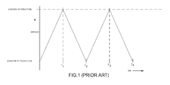
- EP 0566708 B1 describes apparatus for measuring the speed of sound in a fluid in which an electroacoustic transducer at one end of a tube transmits an ultrasonic pulse into fluid present within the tube. This occurs at time zero, represented by the origin of the graph shown in Figure 1 .
- the sound travels along the tube until it reaches the opposite end of that tube where it is reflected by an internal surface across that end.
- T 1 in Figure 1 the sound is reflected back towards the transducer. It reaches the latter at time T 2 whereupon it is reflected by the transducer itself back towards the reflector at the opposite end of the tube, which it reaches the second time at time T 3 .
- the sound is reflected once again by the reflector to arrive back at the transducer at time T 4 .
- the time taken therefore for the sound to travel twice the length of the tube, which is a known distance, is the difference between time T 4 and time T 2 .
- the time delay between when the sensitive surface of the transducer is struck by the sound and the time when that strike is registered within the electronic circuitry of the apparatus, to provide a value of that instant, is the same for both T 4 and T 2 .
- the error introduced by transducer delay occurs at the beginning of the time measurement, so as to delay its commencement, and also at the end of that measurement, so as to delay its cessation by the same amount of time as the delay in its commencement, so that the two errors cancel one another out when T 2 is subtracted from T 4 to provide an accurate measurement of the time taken for the sound to travel up and down the length of the tube, and since that length is known, the speed of sound in the fluid may be determined accurately.
- the pulse may suffer dispersion if the fluid through which it is travelling is a dispersive medium, and in any case the sharpness of the pulse may deteriorate by virtue of scattering of sound from the sides of the tube walls, and the intensity of the pulse may have been attenuated to a level below background noise.
- the present invention seeks to provide a remedy.
- the present invention is directed to apparatus for providing a measure of the time taken for sound to travel a predetermined distance, comprising a transmitter electroacoustic transducer for transmitting an acoustic signal, and a receiver electroacoustic transducer, spaced apart from the transmitter electroacoustic transducer, for receiving the acoustic signal transmitted by the transmitter electroacoustic transducer, the apparatus having a sound reflective surface spaced apart from the receiver electroacoustic transducer so that the latter also receives a reflection of that signal, and timing electrical circuitry connected to the receiver electroacoustic transducer which circuitry serves to provide a measure of the time delay between the respective receptions by the receiver electroacoustic transducer of that signal and its reflection.
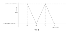
- the reflective surface provided in the present invention may be provided by the transmitter electroacoustic transducer itself, or by a part fixed thereto. This provides an economy of components. If the two transducers are mutually opposed, the sound can be reflected back and forth from one to the other. The result is shown in Figure 2 in which at a time T 1 the first transducer, namely the transmitter electroacoustic transducer, emits a signal, for example a pulse, of ultrasound. This travels towards the second transducer, namely the receiver electroacoustic transducer, to receive the pulse at time T 2 .
- the signal is reflected back towards the first transducer at this instant, which it reaches at time T 3 , to be reflected at that instant back to the second transducer which receives the signal at time T 4 .
- the time taken for the sound signal and/or reflections thereof to travel twice the spacing between the first and second transducers is thus given by the difference between time T 4 and time T 2 , and once again this does not suffer any error owing to the time taken between the instant the sound signal impinges upon the sensitive surface of the transducer to the time this is registered in electronic circuitry of apparatus.
- the electrical circuitry may be such as to cause the operation of the transmitter electroacoustic transducer and the receiver electroacoustic transducer to be reversed.
- the reflective surface 1 could be located spaced apart from both the transmitter electroacoustic transducer 2 and the receiver electroacoustic transducer 3, with the distances between the reflective surface and both the transmitter electroacoustic transducer and the receiver electroacoustic transducer known, as well as the distance between the two transducers, so that the time between the receipt by the receiver electroacoustic transducer of the signal from the transmitter electroacoustic transducer and that from the reflective surface is a measure of the time it takes sound to travel over a distance equal to the distance from one transducer to the other via the reflective surface, less the direct distance between the transducers.
- the present invention may be incorporated in a flowmeter.
- the transducers may be located respectively at opposite ends of a duct along which flows fluid the flow of which is to be measured, and the electronic circuitry may be such as to cause one of the transducers to emit an acoustic signal and to measure the time it takes for that signal to reach the other transducer, and to cause the said other transducer to emit an acoustic signal and to measure the time it takes for that signal to reach the said one transducer, and to calculate the rate of flow of fluid through the duct from the difference between these two measurements.
- the present invention may also be incorporated in an anemometer.
- the transducers may be mounted on a support in such a manner that they are opposed to one another.
- the path between them may be generally horizontal, so that ambient air can pass between them.
- the present invention extends to apparatus for measuring the speed of sound, in which the timing electrical circuitry includes a memory for retaining a value of the distance travelled by the sound during the said time delay, and a processor to enable that value to be divided by the said time delay to provide a measure of the speed of sound.
- a second aspect of the present invention is directed to a method of providing a measure of the time taken for sound to travel a predetermined distance, comprising emitting an acoustic signal from a transmitter electroacoustic transducer and receiving a signal by a receiver electroacoustic transducer which is spaced apart from the transmitter electroacoustic transducer, reflecting the signal from a sound reflective surface spaced apart from the receiver electroacoustic transducer and receiving the reflection by the receiver electroacoustic transducer, and measuring the time delay between the reception by the receiver electroacoustic transducer of the signal and its reflection by means of circuitry connected to the receiver electroacoustic transducer.
- the reflective surface may be provided by the transmitter electroacoustic transducer itself, or by a part fixed thereto. This provides an economy of components, but most importantly it increases the extent to which transducer delay is eliminated. If the two transducers are mutually opposed, the sound can be reflected back and forth from one to the other, as already described with reference to Figure 2 .
- the operation of the transmitter electroacoustic transducer and the receiver electroacoustic transducer may be reversed. An average can then be made of the measurements taken respectively before and after role reversal. This may increase the accuracy of the overall measurement, reducing errors which might be introduced for example by movement of the fluid between the transducers.
- the reflective surface could be located spaced apart from both the transmitter electroacoustic transducer and the receiver electroacoustic transducer, as already described with reference to Figure 3 .
- the second aspect of the present invention may be employed in a flowmeter.
- the transducers may be located respectively at opposite ends of a duct through which flows fluid the flow of which is to be measured, and one of the transducers may be caused to emit an acoustic signal, whereupon the time it takes for that signal to reach the other transducer may be measured, and the said other transducer may be caused to emit an acoustic signal and the time it takes for that signal to reach the said one transducer may be measured, and whereupon the rate of flow of fluid through the duct may be calculated from the differences between these two measurements.
- the speed of wind can be measured using such a pair of transducers mounted on a support so as to be opposed to one another.
- the path between them may be generally horizontal.
- the path between the transducers of one pair may be orthogonal to that between those of the other pair to enable the direction of the wind to be ascertained as well as its speed.
- the present invention also extends to a method of providing a measure of the speed of sound by the method according to the second aspect of the present invention set out hereinbefore, and dividing the distance travelled by the sound during the said time delay by that time delay to obtain a measure of the speed of sound.
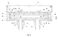
- Figure 4 shows an axial sectional view of a flowmeter incorporating apparatus made in accordance with the present invention
- Figure 5 shows a block circuit diagram of electronic circuitry of the flowmeter shown in Figure 4 ;
- Figure 6 is a flow chart of a computer programme by which the circuitry shown in Figure 5 is set to operate;
- Figure 7 is a plan view of an anemometer incorporating apparatus made in accordance with the present invention, with a part thereof removed to show other parts more clearly;
- Figure 8 shows a side view of the anemometer shown in Figure 7 ;
- Figure 9 shows a side view of a device which embodies the present invention, for measuring the speed of sound in a fluid within the device;
- Figure 10 shows, on a larger scale, an axial sectional view of a central part of the device shown in Figure 9 , taken in the plane indicated by the line X-X in Figure 9 .
- the flowmeter 10 shown in Figure 4 comprises a generally cylindrical inlet port 12 and a generally cylindrical output port 14. These provide respectively an inlet aperture 16 and an outlet aperture 18, both of which are generally circular and are of the same diameter as one another.
- the respective central axes of the inlet and outlet ports extend perpendicularly to a generally cylindrical part 20 of the flowmeter 10, and the ports 12 and 14 open out into respective upstream and downstream annular passageways 22 and 24 which are within the part 20 and are co-axial therewith. These passageways extend into further respective passageways 26 and 28 via respective constrictions to reduce downstream turbulence within the fluid which flows through the flowmeter 10 when the latter is in use.
- a duct 36 which is defined by a generally cylindrical block of glass filled PTFE 38 and which is circular in cross section extends from one end of the cylindrical part 20 to the other, and has flared ends.
- the outer ends of the passageways 26 and 28 are in communication with the ends 34 and 40 of the duct 36 respectively by way of respective radially extending curved passageways 60 and 62.
- the cross-sectional diameter of the duct 36 which is uniform in cross section throughout its length between its flared ends, is significantly less than the diameter of the inlet and outlet apertures 16 and 18.
- a first piezoelectric ceramic ultrasonic transducer 46 is located within a void 94 at one end of the part 20 (the end nearer to the inlet port 12), and a second piezoelectric ultrasonic ceramic transducer 48 is located within the void 96 at the opposite end of the part 20.
- the transducer 46 has a generally planar circular sound-reflective vibratory surface 50 capable of generating and receiving ultrasonic vibrations.
- the diameter of the surface 50 is significantly greater than the cross-sectional diameter of the duct 36.
- the surface 50 faces the duct 36 and is orthogonal to that duct, and has a perpendicular central axis which is co-linear with the central longitudinal axis of the duct 36.
- the transducer 48 has a generally planar circular sound-reflective vibratory surface 52 capable of generating and receiving ultrasonic vibrations.
- the diameter of the surface 52 is the same as that of the surface 50 and also faces the duct 36 and is also orthogonal to the that duct, having a perpendicular central axis which is co-linear with the central longitudinal axis of the duct 36.
- the curved passageways 60 and 62 are defined on their outsides by inner curved surfaces of annular parts 82 and 84 respectively, and on their insides by outer curved surfaces of annular parts 86 and 88 respectively.
- the first piezoelectric ultrasonic transducer 46 has its vibratory surface 50 attached to the rear surface of a thickness-optimised cap 90, whereby ultrasonic vibrations generated in the transducer 46 are transmitted into the fluid in the end 34 of the duct 36, via a vibration surface 91 of the cap 90 facing the duct 36 and provided for the transducer 46.
- the vibration surface 50 is of greater diameter than that of the cross-section of the duct 36.
- the vibration surface 91 is also of greater diameter than that of the cross-section of the duct 36.
- the inner annular part 86 which has a side cross-section which is curved, guides the ultrasound vibrations into the duct 36, through the fluid within which they propagate.
- the transducer 48 has its vibratory surface 52 attached to the rear surface of a thickness-optimised cap 92 through which ultrasonic vibrations present in fluid in the end 40 of the duct 36 are coupled to the transducer 48, via a vibration surface 93 of the cap 92 facing the duct 36 and provided for the transducer 48, to cause the latter to generate electrical signals accordingly.
- the vibration surface 52 is of greater diameter than that of the cross-section of the duct 36.
- the vibration surface 93 is also of greater diameter than that of the cross-section of the duct 36.
- an ultrasonic pulse generated by the transducer 48 can also transmitted through fluid in the duct 36 to be received by and to cause electrical signals to be generated within, the transducer 46.
- the caps 90 and 92 are in sealing contact around their respective peripheries with the inside edges of the annular parts 82 and 84 respectively, so that the transducers 46 and 48 are both isolated from the fluid which flows through the flowmeter 10 when it is in use. Voids 94 and 96 respectively behind the transducers 46 and 48 are air-filled, and the caps 90 and 92 are therefore thick enough to withstand the pressure differential between the fluid and the air when the flowmeter is in use.
- the thickness of the caps 90 and 92 is such as to optimise the coupling of vibration between the transducers 46 and 48 and the fluid in the duct 36 when the flowmeter 10 is in use.
- caps 90 and 92 The thickness of the caps 90 and 92 is reduced where they meet the annular parts 82 and 84 respectively, and the latter parts are so made that they are effective as damping mountings, to reduce signal degradation owing to ringing of the caps 90 and 92.
- the restricted passageways 26 and 28 and the curved passageways 60 and 62 each comprise a series of channels arranged symmetrically around the circumference of the transducers 46 and 48 respectively. Each of these channels open out into the space 34 or 40 in front of the cap 90 or 92 as the case may be, and the flow through each channel is the same to ensure a symmetrical flow entering and leaving the duct 36.
- FIG. 5 shows how each transducer 46 and 48 is connected to receive signals from and send signals to timing electrical circuitry 54 which has a central processor unit to provide a signal at an output 56 thereof indicative of the flow rate of fluid which passes through the flowmeter 10 when the latter is in use.
- fluid the flow of which is to be measured by the flowmeter 10 for example engine fuel such as aviation fuel, petrol or diesel fuel, flows through the inlet port 12, along the annular passageway 22 and the annular passageway 26, and into the end 34 of the duct 36.
- engine fuel such as aviation fuel, petrol or diesel fuel
- the fluid continues from the end 34 of the duct 36, right the way along that duct 36 to the other end thereof where it exits the duct 36 at its other end 40. From here it flows through the curved passageways 62 into the annular passageways 28 and 24 to the outlet port 14 through which it exits the flowmeter 10.
- the voids 94 and 96 behind the transducers 46 and 48 respectively are air-filled, or filled with some other gas or other low density material, and those transducers are thereby isolated from the fluid flowing through the flowmeter 10 when it is use.
- the foregoing construction of flowmeter has a low sensitivity to turbulence variation with flow rate changes. It provides a fast response time, is compact in form and is resistant to outside interference.
- the function of the inlet 12 and the outlet 14 can be readily swapped, so that the function of what is referred to herein as the inlet 12 is changed so that it becomes the outlet, and the function of what is referred to herein as the outlet 14 is changed so that it becomes the inlet.
- the electrical or electronic circuitry 54 with the central processor unit is programmed to operate in the manner shown in Figure 6 whilst fluid flows thus through the flowmeter 10.
- T d L / C + V
- the acoustical signal splits into two parts: one part continues to propagate through the transducer and into the electronics, allowing T 1 to be measured. However, part of the signal is also reflected off the face of the transducer 48. This signal travels from the face of the second transducer 48 back to the first transducer 46. Once it reaches the face of the first transducer 46 again it splits into two parts.
- T 2 the time indicated at which the transducer 46 receives the reflected pulse
- This duration is similar to T d , but because the pulse is now travelling in the opposite direction with respect to the fluid flow, the sign in front of V has changed.
- the processor of the circuitry 54 carries out the last step given in Figure 6 , namely swapping the roles of the transducers 46 and 48 and repeating the cycle of steps in Figure 6 and averaging the values obtained for V and C.
- r is the radius of the cross-section of the duct 36.
- the anemometer shown in Figures 7 and 8 comprises a generally disc-shaped support 100 mounted horizontally on a pedestal 102.
- the latter is of circularly-sectioned cylindrical form, and the edges of the support 100 are rounded to reduce turbulence.
- a disc-shaped cover 104 of the same diameter as the support 100 is held above the latter by four pillars 106 equiangularly spaced around the periphery of the support 100.
- Four electroacoustic transducers 108 are supported on the top of respective pillars 110 (only three of which are visible in Figure 8 ) which extend upwardly from the support 100.
- Each transducer is directed towards the diametrically opposite transducer, so that they together constitute two pairs, with the path between those of one pair being generally orthogonal to the path between those of the other.
- Each pair is connected to timing electrical circuitry 54 as shown in Figure 5 , the latter being programmed to operate the programme illustrated in Figure 6 for each pair.
- timing electrical circuitry 54 as shown in Figure 5 , the latter being programmed to operate the programme illustrated in Figure 6 for each pair.
- a further pair of transducers may be provided with the path between them oriented generally vertically, to measure updraft or downdraft as well as wind speed and direction.
- a measurement of the speed of sound in a medium for example the ambient air, can be used to provide a measure of the temperature of that medium, by way of timing electrical circuitry which has a processor programmed accordingly and provided with a memory in which is held a mapping between the speed of sound in the medium concerned and the temperature of the medium.
- the device 200 shown in Figures 9 and 10 which correspond to parts of the flowmeter shown in Figure 4 have been labelled with the same reference numerals.
- the device 200 shown in Figures 9 and 10 comprises a generally cylindrical hollow part 20 defining a duct or measurement channel 36 within it.
- Inlet and outlet apertures 214 in the part 20 enable fluid (not shown) around the device 12 when it is in use to pass into and out of the channel 36.
- channel 36 which is defined by the interior of the part 20 is circular in cross section and extends from one end of the cylindrical part 20 to the other.
- the cross-sectional diameter of the channel 36 is uniform in cross section throughout its length.
- a first piezoelectric ceramic ultrasonic transducer 46 of a transducer assembly 210 is located within a void 94 at one end of the part 20, and a second piezoelectric ultrasonic ceramic transducer 48 of a transducer assembly 212 is located within the void 96 at the opposite end of the part 20.
- the transducer 46 has a generally planar circular vibratory surface 50 capable of generating and receiving ultrasonic vibrations.
- the surface 50 faces the channel 36 and is orthogonal to that channel, and has a perpendicular central axis which is co-linear with the central longitudinal axis of the channel 36.
- the transducer 48 has a generally planar circular vibratory surface 52 capable of generating and receiving ultrasonic vibrations.
- the diameter of the surface 52 is the same as that of the surface 50 and also faces the channel 36 and is also orthogonal to the that channel, having a perpendicular central axis which is co-linear with the central longitudinal axis of the channel 36.
- the first piezoelectric ultrasonic transducer 46 has its vibratory surface 50 attached to the rear surface of a thickness-optimised cap 90, whereby ultrasonic vibrations generated in the transducer 46 are transmitted into the fluid in the end 34 of the channel 36, via a sound-reflective vibratory surface 91 of the cap 90 facing the channel 36 and provided for the transducer 46. The ultrasound vibrations of the surface 91 are thereby propagated through the channel 36.
- the transducer 48 has its vibratory surface 52 attached to the rear surface of a thickness-optimised cap 92 through which ultrasonic vibrations present in fluid in the end 40 of the channel 36 are coupled to the transducer 48, via a sound-reflective vibratory surface 93 of the cap 92 facing the channel 36 and provided for the transducer 48, to cause the latter to generate electrical signals accordingly.
- an ultrasonic pulse generated by the transducer 48 can also transmitted through fluid in the channel 36 to be received by and to cause electrical signals to be generated within, the transducer 46.
- the caps 90 and 92 are in sealing contact around their respective peripheries with the inside edges of respective annular parts of the transducer assemblies 210 and 212, so that the transducers 46 and 48 are both isolated from the fluid in the channel 36 when the device 200 is in use.
- Voids 94 and 96 respectively behind the transducers 46 and 48 are air-filled, and the caps 90 and 92 are therefore thick enough to withstand the pressure differential between the fluid and the air when the device 200 is in use.
- the thickness of the caps 90 and 92 is such as to optimise the coupling of vibration between the transducers 46 and 48 and the fluid in the channel 36 when the device 200 is in use.
- the thickness of the caps 90 and 92 is reduced where they meet the annular parts of the assemblies 210 and 212 respectively, and the latter parts are so made that they are effective as damping mountings, to reduce signal degradation owing to ringing of the caps 90 and 92.
- the block circuit diagram shown in Figure 5 also shows how each transducer 46 and 48 is connected to receive signals from and send signals to a central processor unit of the circuitry 54.
- the central processor unit of the circuitry 54 is programmed differently from the manner in which it is programmed for the flowmeter 10 of Figure 4 .
- the device 200 it is programmed to provide a signal at an output 56 thereof indicative of the speed of sound in fluid in the channel 36 when the device 200 is in use.
- fluid the speed of sound within which is to be measured by the device 200 for example engine fuel such as aviation fuel, petrol or diesel fuel, is present within the channel 36.
- engine fuel such as aviation fuel, petrol or diesel fuel
- the voids 94 and 96 behind the transducers 46 and 48 respectively are air-filled, or filled with some other gas or other low density material, and those transducers are thereby isolated from the fluid in the channel 36 of the device 200 when it is use.
- the foregoing construction of device 200 has a low sensitivity to turbulence variation in the fluid which surrounds it when it is in use. Although exchange of fluid will occur between that which is within the channel 36 and that which is outside it, via the apertures 214, there is no overall movement of fluid in the axial direction along the channel 36 in this embodiment. It provides a fast response time, is compact in form and is resistant to outside interference.
- the device 200 is reflection symmetrical about a central transverse plane thereof, the roles of the transducers 46 and 48 can be readily reversed.
- the central processor unit of the circuitry 54 is programmed to operate in the manner shown in Figure 6 whilst fluid is present within the channel 36, there being a memory present in the circuitry 54 for retaining a value of the distance travelled (L) by the sound during the time delay (T), and the processor of the circuitry 54 enables that value (L) to be divided by the said time delay (T) to provide a measure of the speed of sound.
Landscapes
- Physics & Mathematics (AREA)
- General Physics & Mathematics (AREA)
- Acoustics & Sound (AREA)
- Engineering & Computer Science (AREA)
- Immunology (AREA)
- Health & Medical Sciences (AREA)
- Life Sciences & Earth Sciences (AREA)
- Chemical & Material Sciences (AREA)
- Analytical Chemistry (AREA)
- Biochemistry (AREA)
- General Health & Medical Sciences (AREA)
- Pathology (AREA)
- Electromagnetism (AREA)
- Fluid Mechanics (AREA)
- Aviation & Aerospace Engineering (AREA)
- Multimedia (AREA)
- Measuring Volume Flow (AREA)
Applications Claiming Priority (1)
| Application Number | Priority Date | Filing Date | Title |
|---|---|---|---|
| GBGB1421607.1A GB201421607D0 (en) | 2014-12-04 | 2014-12-04 | Apparatus and a method for providing a time measurement |
Publications (2)
| Publication Number | Publication Date |
|---|---|
| EP3035006A2 true EP3035006A2 (fr) | 2016-06-22 |
| EP3035006A3 EP3035006A3 (fr) | 2016-07-20 |
Family
ID=52425473
Family Applications (1)
| Application Number | Title | Priority Date | Filing Date |
|---|---|---|---|
| EP15020187.9A Withdrawn EP3035006A3 (fr) | 2014-12-04 | 2015-10-13 | Appareil et procédé pour fournir une mesure de temps |
Country Status (4)
| Country | Link |
|---|---|
| US (1) | US20160161525A1 (fr) |
| EP (1) | EP3035006A3 (fr) |
| AU (1) | AU2015249080A1 (fr) |
| GB (1) | GB201421607D0 (fr) |
Families Citing this family (5)
| Publication number | Priority date | Publication date | Assignee | Title |
|---|---|---|---|---|
| JP6191871B2 (ja) * | 2014-01-09 | 2017-09-06 | パナソニックIpマネジメント株式会社 | 流量計測装置 |
| CA2981860C (fr) * | 2015-04-12 | 2020-12-08 | Metek Meteorologische Messtechnik Gmbh | Anemometre ultrasonique et methode de determination d'au moins une composante d'un vecteur de la vitesse eolienne ou la vitesse dans l'atmosphere |
| US11125770B2 (en) * | 2018-12-06 | 2021-09-21 | Rosemount Aerospace Inc. | Acoustic air data sensor and system |
| US11885655B2 (en) * | 2020-08-07 | 2024-01-30 | Woodward, Inc. | Ultrasonic flow meter having flow conditioning arrangements for flow controlling in a linear fluid conduit |
| CN112577588A (zh) * | 2020-12-23 | 2021-03-30 | 中国石油大学(北京) | 声速测量装置 |
Citations (1)
| Publication number | Priority date | Publication date | Assignee | Title |
|---|---|---|---|---|
| EP0566708B1 (fr) | 1991-09-16 | 1997-04-23 | British Gas plc | Systeme de mesure |
Family Cites Families (7)
| Publication number | Priority date | Publication date | Assignee | Title |
|---|---|---|---|---|
| US4112756A (en) * | 1977-08-26 | 1978-09-12 | Canadian Patents And Development Limited | Ultrasonic air data system |
| GB9301873D0 (en) * | 1993-01-30 | 1993-03-17 | Cambridge Consultants | Method and apparatus for fluid flow metering |
| US5591945A (en) * | 1995-04-19 | 1997-01-07 | Elo Touchsystems, Inc. | Acoustic touch position sensor using higher order horizontally polarized shear wave propagation |
| EP0768629A1 (fr) * | 1995-10-13 | 1997-04-16 | MATRIX S.a.s. di G. DE ZORZI e C. | Système d'alarme pour articles confinés dans une portée prédéterminée |
| GB9917985D0 (en) * | 1999-07-30 | 1999-09-29 | Scient Generics Ltd | Acoustic communication system |
| US7574894B2 (en) * | 2006-04-25 | 2009-08-18 | Parker-Hannifin Corporation | ASM output ultrasonic oxygen sensor |
| US7934432B2 (en) * | 2007-02-27 | 2011-05-03 | Dräger Medical GmbH | Method for measuring the run time of an ultrasonic pulse in the determination of the flow velocity of a gas in a breathing gas volume flow sensor |
-
2014
- 2014-12-04 GB GBGB1421607.1A patent/GB201421607D0/en not_active Ceased
-
2015
- 2015-10-13 EP EP15020187.9A patent/EP3035006A3/fr not_active Withdrawn
- 2015-10-28 AU AU2015249080A patent/AU2015249080A1/en not_active Abandoned
- 2015-11-30 US US14/953,709 patent/US20160161525A1/en not_active Abandoned
Patent Citations (1)
| Publication number | Priority date | Publication date | Assignee | Title |
|---|---|---|---|---|
| EP0566708B1 (fr) | 1991-09-16 | 1997-04-23 | British Gas plc | Systeme de mesure |
Also Published As
| Publication number | Publication date |
|---|---|
| US20160161525A1 (en) | 2016-06-09 |
| EP3035006A3 (fr) | 2016-07-20 |
| AU2015249080A1 (en) | 2016-06-23 |
| GB201421607D0 (en) | 2015-01-21 |
Similar Documents
| Publication | Publication Date | Title |
|---|---|---|
| US9261389B2 (en) | Ultrasonic flowmeter | |
| KR960013251B1 (ko) | 초음파 유량측정 방법과 장치 | |
| JP5292001B2 (ja) | 流量計の現場較正用のシステムおよび方法 | |
| CN104870950B (zh) | 用于验证按渡越时间差法进行的超声波流量测量所获知的测量数据的可靠性的方法以及超声波流量计 | |
| CN100455999C (zh) | 一种超声波测量液位的装置及方法 | |
| EP3035006A2 (fr) | Appareil et procédé pour fournir une mesure de temps | |
| JP2012509460A (ja) | 超音波流量計 | |
| CN102829829B (zh) | 一种时差法超声波流量检测方法及装置 | |
| CN104236648A (zh) | 超声波流量计 | |
| KR101195438B1 (ko) | 초음파 유량계 및 초음파 유량측정방법 | |
| CN102914333B (zh) | 利用超声波检测流量的检测方法 | |
| JP2009008406A (ja) | 超音波流量計及び超音波送受波器ユニット | |
| JP7006354B2 (ja) | 計測装置 | |
| CN108474766B (zh) | 声学确定介质特性的方法和借助反射元件声学确定介质特性的设备 | |
| CN102829830B (zh) | 用于超声波流量检测中检测超声波传播速度的方法及装置 | |
| CN116261651A (zh) | 流量测量装置和用于测量流体的流量的方法 | |
| JP7151311B2 (ja) | 超音波流量計 | |
| CN103245384B (zh) | 一种用于超声燃气表中的超声波流量气室 | |
| CN100380101C (zh) | 多普勒型超声波流量计 | |
| JP4688253B2 (ja) | 超音波流量計 | |
| JP2011038870A (ja) | 超音波流量計およびこれを用いた流速測定方法 | |
| CN102023038A (zh) | 一种管道流量的超声波测量方法 | |
| CN202734881U (zh) | 超声波流量检测装置 | |
| JP4827008B2 (ja) | 超音波流量計、超音波トランスジューサ、超音波送受信ユニットおよび超音波流量計を用いた流量測定方法 | |
| CN202710116U (zh) | 一种超声波流量检测装置 |
Legal Events
| Date | Code | Title | Description |
|---|---|---|---|
| PUAI | Public reference made under article 153(3) epc to a published international application that has entered the european phase |
Free format text: ORIGINAL CODE: 0009012 |
|
| PUAL | Search report despatched |
Free format text: ORIGINAL CODE: 0009013 |
|
| AK | Designated contracting states |
Kind code of ref document: A2 Designated state(s): AL AT BE BG CH CY CZ DE DK EE ES FI FR GB GR HR HU IE IS IT LI LT LU LV MC MK MT NL NO PL PT RO RS SE SI SK SM TR |
|
| AX | Request for extension of the european patent |
Extension state: BA ME |
|
| AK | Designated contracting states |
Kind code of ref document: A3 Designated state(s): AL AT BE BG CH CY CZ DE DK EE ES FI FR GB GR HR HU IE IS IT LI LT LU LV MC MK MT NL NO PL PT RO RS SE SI SK SM TR |
|
| AX | Request for extension of the european patent |
Extension state: BA ME |
|
| RIC1 | Information provided on ipc code assigned before grant |
Ipc: G01P 5/24 20060101ALI20160615BHEP Ipc: G01F 1/66 20060101AFI20160615BHEP Ipc: G01H 5/00 20060101ALI20160615BHEP |
|
| STAA | Information on the status of an ep patent application or granted ep patent |
Free format text: STATUS: THE APPLICATION HAS BEEN PUBLISHED |
|
| STAA | Information on the status of an ep patent application or granted ep patent |
Free format text: STATUS: THE APPLICATION IS DEEMED TO BE WITHDRAWN |
|
| 18D | Application deemed to be withdrawn |
Effective date: 20170121 |