EP3035496A1 - Rotor pour une machine électrique à aimants permanents - Google Patents
Rotor pour une machine électrique à aimants permanents Download PDFInfo
- Publication number
- EP3035496A1 EP3035496A1 EP14198232.2A EP14198232A EP3035496A1 EP 3035496 A1 EP3035496 A1 EP 3035496A1 EP 14198232 A EP14198232 A EP 14198232A EP 3035496 A1 EP3035496 A1 EP 3035496A1
- Authority
- EP
- European Patent Office
- Prior art keywords
- rotor
- magnetic poles
- electric machine
- angular distances
- stator
- Prior art date
- Legal status (The legal status is an assumption and is not a legal conclusion. Google has not performed a legal analysis and makes no representation as to the accuracy of the status listed.)
- Granted
Links
Images

Classifications
-
- H—ELECTRICITY
- H02—GENERATION; CONVERSION OR DISTRIBUTION OF ELECTRIC POWER
- H02K—DYNAMO-ELECTRIC MACHINES
- H02K1/00—Details of the magnetic circuit
- H02K1/06—Details of the magnetic circuit characterised by the shape, form or construction
- H02K1/22—Rotating parts of the magnetic circuit
- H02K1/27—Rotor cores with permanent magnets
- H02K1/2706—Inner rotors
- H02K1/272—Inner rotors the magnetisation axis of the magnets being perpendicular to the rotor axis
- H02K1/274—Inner rotors the magnetisation axis of the magnets being perpendicular to the rotor axis the rotor consisting of two or more circumferentially positioned magnets
- H02K1/2753—Inner rotors the magnetisation axis of the magnets being perpendicular to the rotor axis the rotor consisting of two or more circumferentially positioned magnets the rotor consisting of magnets or groups of magnets arranged with alternating polarity
- H02K1/278—Surface mounted magnets; Inset magnets
-
- H—ELECTRICITY
- H02—GENERATION; CONVERSION OR DISTRIBUTION OF ELECTRIC POWER
- H02K—DYNAMO-ELECTRIC MACHINES
- H02K29/00—Motors or generators having non-mechanical commutating devices, e.g. discharge tubes or semiconductor devices
- H02K29/03—Motors or generators having non-mechanical commutating devices, e.g. discharge tubes or semiconductor devices with a magnetic circuit specially adapted for avoiding torque ripples or self-starting problems
-
- H—ELECTRICITY
- H02—GENERATION; CONVERSION OR DISTRIBUTION OF ELECTRIC POWER
- H02K—DYNAMO-ELECTRIC MACHINES
- H02K2213/00—Specific aspects, not otherwise provided for and not covered by codes H02K2201/00 - H02K2211/00
- H02K2213/03—Machines characterised by numerical values, ranges, mathematical expressions or similar information
Definitions
- the present invention relates to a rotor for a permanent-magnet excited electric machine having eight magnetic poles mounted along its outer circumference in a ring arrangement. Moreover, the invention comprises an electric machine having a rotor and a stator, wherein eight magnetic poles are mounted along an outer circumference of the rotor in a ring arrangement.
- Permanent-magnet electric machines have high reliability and can be operated with high efficiency.
- the permanent-magnet electric machines can be operated as a motor or as a generator.
- the permanent magnet excited electric machine can be used for example as a servomotor.
- Servo motors have a variety of applications. They are often used in industrial plants. They can also be used in various machines, for example in machine tools, packaging machines or industrial robots.
- the describes DE 103 48 401 A1 a rotating machine with permanent magnets, which has a rotor with a rotor core.
- the rotor carries on its curved outer surface a plurality of permanent magnets arranged in two rows along an axial direction in a manner such that the permanent magnets in one row are offset obliquely from those in another row by an oblique offset angle between the rows.
- the permanent magnets which form a pair of north and south poles, can be obliquely offset with respect to the points at the same angle by as much as 15 ° or 3.75 ° with respect to the mechanical angle.
- FIG. 2 A special rotor structure, by which the parasitic effects are to be kept low, is exemplified in FIG. 2 (Prior art) shown.
- Out FIG. 2 goes out a rotor 16 with staggered magnetic poles 18.
- Adjacent magnetic poles 18 have in the circumferential direction per relay disc, the same distance or the same relative angular position to each other.
- the magnets For an 8-pole rotor, the magnets have an angular distance of 45 °.
- the object of the invention is to keep the torque ripple particularly low.
- this object is achieved by a rotor for a permanent magnet-excited electric machine with eight magnetic poles mounted along its outer circumference in a ring arrangement.
- there are angular distances between the respective adjacent magnetic poles which are successively 41, 25, 39, 75, 41, 25, 57, 57, 41, 25, 39, 75, 41, 25 and 57, 57.
- the respective angular distances have a tolerance range of 0.4 °.
- the magnetic poles can thus have a positioning accuracy of ⁇ 0.4 °.
- the magnetic poles are arranged on the circumference of the rotor with different relative position angles.
- the magnets may, for example, be arranged in a ring arrangement such that their center is cut by a hypothetical straight line which extends from a center point of the rotor to the center of the magnet, with a straight line at a respective angular distance also starting from the rotor center point extends further hypothetical straight line which also passes through the center of another adjacent magnet.
- Angular distance means the distance which results between two straight lines, the straight lines extending from the center of the rotor (rotor axis) extending radially outwards to the center of the magnetic poles. The angular distance is thereby expressed in degrees, e.g. 45 °, measured.
- tolerance range is here meant a positive or negative value of a deviation from the respective value of the angular distance between the respectively adjacent magnetic poles.
- the sum of all eight values for the angular distances between the magnetic poles results in a total of 360 °.
- the corresponding arrangement of the magnetic poles on the circumference of the rotor affords the advantage that interference effects, such as, for example, fluctuating torques, are reduced.
- the magnetic poles are designed as shell magnets.
- Shell magnets are characterized by the fact that their underside, ie the surface which rests on the laminated core of the rotor, and the upper side, ie the surface opposite the underside, curved in such a way are that their curvatures coincide with the curvature of the circle with the same radial distance from the axis of rotation. This has the advantage that a narrow and uniform air gap between Magnetpolober Design and Statorinnen Activities or Polschuh Formation can be made possible and yet a tight fit is ensured on the laminated core.
- flow barriers can run in the laminated core, wherein the flow barriers are arranged radially inwardly and centrally at a predetermined distance from the magnetic poles.
- in-house it is meant here that the flow barriers are under, i. in the direction of the rotor center, the magnetic poles are arranged.
- cavities are meant, which may for example have a cylindrical shape. This has the advantage that the rotor is lighter and thus has a very low weight. In addition, no magnetic short circuits occur due to the presence of the flux barriers. Both causes particularly low losses occur during operation of the electrical machine.
- Another embodiment provides that a further ring arrangement of eight magnetic poles and corresponding magnetic poles of all ring arrangements are arranged axially aligned.
- axially aligned is meant here that the magnetic poles are arranged along a parallel to the axis of rotation.
- the magnetic poles can be mounted straight on the rotor. This has the advantage that a magnetization on the rotor with straight magnetizing yokes is possible. This simplifies the production technology and the number of production tools.
- the invention also includes an electric machine having a rotor and a stator, wherein eight magnet poles are mounted along an outer circumference of the rotor in a ring arrangement are. Between the respective adjacent magnetic poles are angular distances to each other, wherein the angular intervals successively 41,25, 39,75, 41,25, 57,75, 41,25, 39,75, 41,25 and 57,75 amount.
- the respective angular distances have a tolerance range of 0.4 °. The possible tolerances result in a particularly smooth course of the torque ripple.
- the rotor may be arranged in a stator with 48 slots and 49 tooth coils.
- the rotor is associated with a stator with 48 slots and 48 tooth coils.
- the electric machine can have a Polvereckung between 0.6 and 0.7.
- Pole coverage here means the ratio of the angle of projection of the magnet on the stator bore to the pole angle. In other words, the pole coverage results from the ratio of the magnetic angle to the pole angle.
- the magnetic angle can be determined by starting from two magnetic edges, i.
- the magnetic angle corresponds to the angle between these two straight lines.
- the horizontal distance between the magnetic edges or the first and the second edge of the magnet represents the magnet width.
- the pole angle as well as the magnetic angle are given in degrees.
- the quantity p represents the number of pole pairs or the pole pair number, which is multiplied by 2.
- the number of pole pairs in an 8-pole electric machine corresponds to the value 4.
- FIG. 1 a general structure of an electric machine is shown.
- an axis of rotation A is also an axis of symmetry of the illustration.
- the electric machine 10 comprises a stator 14 in which windings W of electrical coils are arranged, wherein FIG. 1 only one of the windings W is shown.
- the windings W become energized alternately by a three-phase current source C, whereby in the interior of the stator 14, a magnetic rotating field in an air gap L of the electric machine 10 is formed.
- the three-phase current source C can be, for example, an inverter or a fixed-frequency electrical supply network.
- a rotor 16 which is rotatably connected to a shaft 12.
- the shaft 12 is rotatable about the rotation axis A and supported in the stator 14.
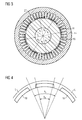
- FIG. 3 a section of an electric machine 10 and a stator 14 and a rotor 16 is shown.
- the electric machine 10 may be a motor such as a PM (PM) permanent magnet motor or a generator.
- the rotor 16 has eight magnetic poles 18 mounted along its outer circumference in a ring arrangement.
- each adjacent magnetic poles 18 are angular distances a1 to a8, wherein the angular distances successively 41,25, 39,75, 41,25, 57,75, 41,25, 39,75, 41,25 and 57,75 amount.
- the respective angular distances a1 to a8 can have a tolerance range of 0.4 °, but the sum of all angular distances always yields 360 °.
- the rotor 16 has a number of holes of 2.
- the magnetic poles 18 are alternately north and south poles.
- the rotor 16 is associated with the stator 14 with 48 slots 20 and 48 tooth coils.
- FIG. 4 shows a schematic representation of a section of the rotor 16 according to the invention.
- Magnetic poles 18 are arranged on the circumference of the rotor 16. Between the rotor 16 and the stator 14, an air gap L is formed.
- the pole angle a p can be calculated by the formula: 360 ° / (2 * p), where in the denominator the quantity p corresponds to the number of pole pairs.
- the magnet width results from the calculation of the horizontal distance between the first and the second magnetic edge, which is arranged in the circumferential direction of the rotor relative to the first edge.
- a magnetic pole 18 consists of three magnets.
- the electric machine 10 has a pole coverage between 0.6 and 0.7.
- the embodiment shows a combination of different position angles of the magnetic poles on the circumference of the motor with an associated Polübereckung (magnetic width / pole pitch).
- the magnets can be placed straight on the rotor. This magnetization on the rotor with straight magnetizing yokes is possible. This simplifies the production technology and the number of production tools.
- the most pronounced technical effect is the combination of partial pole coverage and position angles. The position angles were created by turning individual poles.
- the electric vehicle drives are rail-bound vehicles, such as trams, multiple units, locomotives, as well as e-cars, mining trucks and applications for e-aircraft.
- the reduced torque ripple and the simple structure is intended primarily for machine tools and tool machining, as well as the application of such electrical machines in industrial robots, packaging machines or logistics centers.
- the electrical machine is mainly used as a servomotor, which is particularly suitable due to its control of the angular position of the shaft of the electric machine and the rotational speed and acceleration.
Landscapes
- Engineering & Computer Science (AREA)
- Power Engineering (AREA)
- Permanent Field Magnets Of Synchronous Machinery (AREA)
- Permanent Magnet Type Synchronous Machine (AREA)
- Iron Core Of Rotating Electric Machines (AREA)
Priority Applications (3)
| Application Number | Priority Date | Filing Date | Title |
|---|---|---|---|
| EP14198232.2A EP3035496B1 (fr) | 2014-12-16 | 2014-12-16 | Rotor pour une machine électrique à aimants permanents |
| US14/969,815 US9954404B2 (en) | 2014-12-16 | 2015-12-15 | Permanently magnetically excited electric machine |
| CN201510938140.8A CN105703505B (zh) | 2014-12-16 | 2015-12-15 | 永磁激励的电机 |
Applications Claiming Priority (1)
| Application Number | Priority Date | Filing Date | Title |
|---|---|---|---|
| EP14198232.2A EP3035496B1 (fr) | 2014-12-16 | 2014-12-16 | Rotor pour une machine électrique à aimants permanents |
Publications (2)
| Publication Number | Publication Date |
|---|---|
| EP3035496A1 true EP3035496A1 (fr) | 2016-06-22 |
| EP3035496B1 EP3035496B1 (fr) | 2017-02-01 |
Family
ID=52023397
Family Applications (1)
| Application Number | Title | Priority Date | Filing Date |
|---|---|---|---|
| EP14198232.2A Active EP3035496B1 (fr) | 2014-12-16 | 2014-12-16 | Rotor pour une machine électrique à aimants permanents |
Country Status (3)
| Country | Link |
|---|---|
| US (1) | US9954404B2 (fr) |
| EP (1) | EP3035496B1 (fr) |
| CN (1) | CN105703505B (fr) |
Families Citing this family (2)
| Publication number | Priority date | Publication date | Assignee | Title |
|---|---|---|---|---|
| DE102019123031A1 (de) * | 2019-08-28 | 2021-03-04 | Valeo Siemens Eautomotive Germany Gmbh | Rotor für eine elektrische Maschine und elektrische Maschine |
| CN110829771A (zh) * | 2019-09-30 | 2020-02-21 | 珠海运控电机有限公司 | 无缝电枢绕组永磁同步电动机 |
Citations (4)
| Publication number | Priority date | Publication date | Assignee | Title |
|---|---|---|---|---|
| US4713569A (en) * | 1986-06-20 | 1987-12-15 | 501 Aeroflex Laboratories, Incorporated | Low cogging motor |
| DE10348401A1 (de) | 2002-10-18 | 2004-05-19 | Mitsubishi Denki K.K. | Umlaufende Maschine mit Dauermagneten |
| WO2004070921A1 (fr) * | 2003-01-30 | 2004-08-19 | Rexroth Indramat Gmbh | Machine a courant triphase presentant des caracteristiques de fonctionnement optimisees. |
| EP2073352A1 (fr) * | 2007-12-17 | 2009-06-24 | Siemens Aktiengesellschaft | Machine synchrone à excitation permanente dotée d'aimants à coque |
Family Cites Families (62)
| Publication number | Priority date | Publication date | Assignee | Title |
|---|---|---|---|---|
| US6242837B1 (en) * | 1997-09-29 | 2001-06-05 | Hitachi, Ltd. | Permanent magnet rotary machine and electric vehicle using the same |
| DE19842948A1 (de) | 1998-09-18 | 2000-03-30 | Siemens Ag | Elektromotor |
| DE10133654A1 (de) | 2001-07-11 | 2003-02-06 | Siemens Ag | Synchronmaschine |
| DE10153750A1 (de) | 2001-10-31 | 2003-05-22 | Siemens Ag | Rotor für PM-Synchronmaschine |
| DE10156782C1 (de) | 2001-11-19 | 2003-04-17 | Siemens Ag | Gebersystem für einen Ferraris-Bewegungsgeber |
| DE10236941A1 (de) | 2002-08-12 | 2004-03-04 | Siemens Ag | Stator für eine Synchronmaschine |
| DE10236942A1 (de) | 2002-08-12 | 2004-03-04 | Siemens Ag | Blechpaket für eine elektrische Maschine |
| DE10248771A1 (de) | 2002-10-18 | 2004-04-29 | Siemens Ag | Permanenterregte Synchronmaschine |
| DE10258778A1 (de) | 2002-12-16 | 2004-07-22 | Siemens Ag | Elektrische Maschine mit Heatpipes |
| DE10317591A1 (de) | 2003-04-16 | 2004-11-11 | Siemens Ag | Optischer Geber für drehzahlregelbare Motoren |
| DE10324664A1 (de) | 2003-05-30 | 2004-12-30 | Siemens Ag | Rollen und Rollenmotoren |
| DE10324601A1 (de) | 2003-05-30 | 2004-12-16 | Siemens Ag | Antriebsvorrichtung für Linear- und Rotationsbewegung |
| JP4772503B2 (ja) | 2003-09-11 | 2011-09-14 | シーメンス アクチエンゲゼルシヤフト | かご形誘導巻線導体を有する永久磁石式回転子を備えた三相同期機、および牽引駆動装置ならびに生産機械装置 |
| CN1839526A (zh) | 2003-09-11 | 2006-09-27 | 西门子公司 | 具有一感应转子的电机 |
| JP4062269B2 (ja) * | 2004-03-11 | 2008-03-19 | 日産自動車株式会社 | 同期型回転電機 |
| DE102004044701B4 (de) | 2004-09-15 | 2008-01-31 | Siemens Ag | Synchronmaschine |
| DE102004044697B4 (de) | 2004-09-15 | 2009-02-26 | Siemens Ag | Synchronmaschine |
| DE102004044700B4 (de) | 2004-09-15 | 2008-04-24 | Siemens Ag | Synchronmaschine |
| DE102004044699B4 (de) | 2004-09-15 | 2006-08-31 | Siemens Ag | Synchronmaschine |
| DE102004045939B4 (de) | 2004-09-22 | 2010-10-07 | Siemens Ag | Permanenterregte Synchronmaschine mit Unterdrückungsmitteln zur Verbesserung der Drehmomentwelligkeit |
| DE102004046821A1 (de) | 2004-09-27 | 2006-04-06 | Siemens Ag | Kühleinrichtung einer elektrischen Maschine |
| DE102004056210A1 (de) | 2004-11-22 | 2006-06-01 | Siemens Ag | Rotationslinearantrieb mit axialkraftfreiem Rotationsantrieb |
| DE102004056211B4 (de) | 2004-11-22 | 2011-08-18 | Siemens AG, 80333 | Rotationslinearantrieb mit Gebereinrichtung |
| DE102004056212A1 (de) | 2004-11-22 | 2006-06-01 | Siemens Ag | Elektrische Maschine mit einem rotatorischen und einem linearen Aktuator |
| DE102004058046B4 (de) | 2004-12-01 | 2012-10-31 | Siemens Ag | Hochpolige permanenterregte Synchronmaschine mit Zahnspulen |
| DE102004060351A1 (de) | 2004-12-15 | 2006-07-06 | Siemens Ag | Elektromotor für Rotation und Axialbewegung |
| DE102005016257B4 (de) | 2005-04-08 | 2008-03-13 | Siemens Ag | Reluktanzmotor |
| DE102005016856A1 (de) | 2005-04-12 | 2006-10-19 | Siemens Ag | Elektrische Asynchronmaschine mit Zahnspulen im Stator-Wicklungssystem |
| DE102005019112A1 (de) | 2005-04-25 | 2006-10-26 | Siemens Ag | Kombinationsantrieb mit Hybridreluktanzmotor |
| DE102005022548A1 (de) | 2005-05-17 | 2006-11-23 | Siemens Ag | Elektrische Maschine mit einem Wicklungssystem mit Spulengruppen |
| DE102005030878B4 (de) | 2005-07-01 | 2010-09-02 | Siemens Ag | Vorrichtung und Verfahren zur Erfassung der Mittenabweichung einer Welle |
| DE102005030826A1 (de) | 2005-07-01 | 2007-01-04 | Siemens Ag | Synchronmaschine |
| DE102005039176A1 (de) | 2005-08-18 | 2007-02-22 | Siemens Ag | Elektrische Maschine mit winkelversetzten Einzelspulen |
| JP2007097387A (ja) * | 2005-08-31 | 2007-04-12 | Toshiba Corp | 回転電機 |
| DE102005057370B4 (de) | 2005-12-01 | 2011-12-29 | Siemens Ag | Rotationslinearantriebsanordnung |
| DE102006002900B4 (de) | 2006-01-20 | 2007-12-20 | Siemens Ag | Elektrische Maschine mit einem dreisträngigen Wicklungssystem |
| DE102006012736A1 (de) | 2006-03-17 | 2007-09-20 | Siemens Ag | Elektrische Maschine |
| DE102006027819A1 (de) | 2006-06-16 | 2007-12-20 | Siemens Ag | Ringspulenmotor |
| DE102006033718B4 (de) | 2006-07-20 | 2017-10-19 | Siemens Aktiengesellschaft | Elektrische Maschine mit schräg verlaufenden Magnetpolgrenzen |
| DE102007004095B4 (de) | 2007-01-26 | 2009-07-30 | Siemens Ag | Bremse für eine linear und rotatorisch bewegliche Welle |
| DE102007020274B4 (de) | 2007-04-30 | 2009-04-02 | Siemens Ag | Messsystem zum Erfassen einer Dreh-Linear-Bewegung und entsprechender Drehlinearantrieb |
| DE102007021322A1 (de) | 2007-05-07 | 2008-11-13 | Siemens Ag | Linearantriebsmodul für einen Dreh-Linear-Antrieb |
| EP2073351A1 (fr) | 2007-12-17 | 2009-06-24 | Siemens Aktiengesellschaft | Elément secondaire d'un entraînement linéaire |
| EP2139100B1 (fr) | 2008-06-27 | 2012-10-31 | Siemens Aktiengesellschaft | Machine synchrone à aimants permanents dotée d'une ondulation de couple réduite |
| EP2148104A1 (fr) | 2008-07-21 | 2010-01-27 | Siemens Aktiengesellschaft | Palier radial magnétique et système de palier magnétique avec alimentation en courant électrique |
| EP2148410A1 (fr) | 2008-07-21 | 2010-01-27 | Siemens Aktiengesellschaft | Machine électrique dotée d'une construction d'enroulement à gradins |
| EP2148103B1 (fr) | 2008-07-21 | 2011-01-26 | Siemens Aktiengesellschaft | Palier radial magnétique avec préaimantation par des aimants permanents et système de stockage magnétique doté d'un tel palier radial magnétique |
| EP2192670A1 (fr) | 2008-12-01 | 2010-06-02 | Siemens Aktiengesellschaft | Machine synchrone à excitation permanente comprenant 10 pôles, 12 encoches et un rotor ayant une géométrie optimisée |
| DE102009038691A1 (de) | 2009-08-24 | 2011-03-03 | Siemens Aktiengesellschaft | Elektrische Maschine |
| DE102010001481A1 (de) | 2010-02-02 | 2011-08-04 | Siemens Aktiengesellschaft, 80333 | Rotor einer permanenterregten Synchronmaschine |
| DE102010001997B4 (de) | 2010-02-16 | 2016-07-28 | Siemens Aktiengesellschaft | Linearmotor mit verminderter Kraftwelligkeit |
| DE102010028872A1 (de) | 2010-05-11 | 2011-11-17 | Siemens Aktiengesellschaft | Antriebsvorrichtung für Dreh- und Linearbewegungen mit entkoppelten Trägheiten |
| EP2463992B1 (fr) | 2010-12-08 | 2015-07-29 | Siemens Aktiengesellschaft | Moteur électrique aux aimants permanents doté d'un dispositif de chauffage et procédé de fonctionnement |
| EP2523320A1 (fr) | 2011-05-13 | 2012-11-14 | Siemens Aktiengesellschaft | Entraînement de combinaison pour un mouvement de rotation et de levée et moteur linéaire ayant une inertie réduite |
| EP2523319B1 (fr) | 2011-05-13 | 2013-12-18 | Siemens Aktiengesellschaft | Moteur linéaire cylindrique à faible pulsation de couple |
| ES2495421T3 (es) | 2011-05-20 | 2014-09-17 | Siemens Aktiengesellschaft | Cojinete radial magnético con excitación trifásica |
| JP2013162556A (ja) * | 2012-02-01 | 2013-08-19 | Suzuki Motor Corp | 電動回転機 |
| EP2639936B1 (fr) | 2012-03-16 | 2015-04-29 | Siemens Aktiengesellschaft | Machine électrique à rotor excité en permanence et rotor excité en permanence correspondant |
| EP2639935B1 (fr) * | 2012-03-16 | 2014-11-26 | Siemens Aktiengesellschaft | Rotor à excitation permanente, machine électrique dotée d'un tel rotor et procédé de fabrication du rotor |
| EP2639934B1 (fr) | 2012-03-16 | 2015-04-29 | Siemens Aktiengesellschaft | Rotor à excitation permanente, machine électrique dotée d'un tel rotor et procédé de fabrication du rotor |
| EP2696469B1 (fr) | 2012-08-09 | 2015-06-17 | Siemens Aktiengesellschaft | Rotor pour une machine synchrone à excitation permanente |
| EP2709238B1 (fr) | 2012-09-13 | 2018-01-17 | Siemens Aktiengesellschaft | Machine synchrone à excitation permanente dotée d'aimants en ferrite |
-
2014
- 2014-12-16 EP EP14198232.2A patent/EP3035496B1/fr active Active
-
2015
- 2015-12-15 CN CN201510938140.8A patent/CN105703505B/zh active Active
- 2015-12-15 US US14/969,815 patent/US9954404B2/en active Active
Patent Citations (5)
| Publication number | Priority date | Publication date | Assignee | Title |
|---|---|---|---|---|
| US4713569A (en) * | 1986-06-20 | 1987-12-15 | 501 Aeroflex Laboratories, Incorporated | Low cogging motor |
| DE10348401A1 (de) | 2002-10-18 | 2004-05-19 | Mitsubishi Denki K.K. | Umlaufende Maschine mit Dauermagneten |
| WO2004070921A1 (fr) * | 2003-01-30 | 2004-08-19 | Rexroth Indramat Gmbh | Machine a courant triphase presentant des caracteristiques de fonctionnement optimisees. |
| DE10303848A1 (de) | 2003-01-30 | 2004-08-19 | Rexroth Indramat Gmbh | Drehstrommaschine mit optimierten Laufeigenschaften |
| EP2073352A1 (fr) * | 2007-12-17 | 2009-06-24 | Siemens Aktiengesellschaft | Machine synchrone à excitation permanente dotée d'aimants à coque |
Also Published As
| Publication number | Publication date |
|---|---|
| US20160172915A1 (en) | 2016-06-16 |
| EP3035496B1 (fr) | 2017-02-01 |
| US9954404B2 (en) | 2018-04-24 |
| CN105703505A (zh) | 2016-06-22 |
| CN105703505B (zh) | 2018-06-01 |
Similar Documents
| Publication | Publication Date | Title |
|---|---|---|
| EP2696469B1 (fr) | Rotor pour une machine synchrone à excitation permanente | |
| EP2327136B1 (fr) | Moteur synchrone à aimant permanent et servodirection électrique | |
| EP2192670A1 (fr) | Machine synchrone à excitation permanente comprenant 10 pôles, 12 encoches et un rotor ayant une géométrie optimisée | |
| EP2991195A1 (fr) | Machine dynamométrique à excitation permanente | |
| DE102015110652B4 (de) | Rotor-stator-anordnung für eine hybriderregte synchronmaschine und ein rotor dafür | |
| EP2427951B1 (fr) | Machine electrique synchrone | |
| EP3479458B1 (fr) | Rotor, procédé de fabrication d'un rotor, machine à reluctance et machine de travail | |
| DE102013200476A1 (de) | Permanenterregte Synchronmaschine mit einem Rotor mit Permanentmagneten und Verfahren zur Herstellung derartiger Maschinen bzw. Rotoren | |
| EP3352331A1 (fr) | Tôle de rotor pour un moteur électrique à excitation permanente et rotor | |
| DE102017222683A1 (de) | Elektrische Maschine | |
| DE102005042543A1 (de) | Permanenterregte Synchronmaschine | |
| EP3167537B1 (fr) | Rotor doté d'arêtes dépassant vers l'intérieur | |
| EP2805406A2 (fr) | Machine électrique en secteur comprenand enroulement monocouche à nombre fractionnaire d'encoches par pôle et phase | |
| EP3035495A1 (fr) | Rotor pour une machine électrique à aimants permanents | |
| DE102015212127A1 (de) | Permanent erregte elektrische Maschine mit optimierter Geometrie | |
| EP3035496B1 (fr) | Rotor pour une machine électrique à aimants permanents | |
| EP2999090A1 (fr) | Rotor excité en permanence présentant un champ magnétique guidé | |
| DE102009032881A1 (de) | Segmentierter Ständer für eine dynamoelektrische Maschine | |
| EP2966756A1 (fr) | Rotor pour une machine électrique à aimants permanents | |
| EP3522338A1 (fr) | Rotor à canaux de refroidissement | |
| WO2017012765A1 (fr) | Machine électrique à excitation permanente avec géométrie optimisée | |
| EP3154176A1 (fr) | Moteur d'entraînement électrique | |
| EP2871752B1 (fr) | Rotor d'une machine synchrone rotative à excitation permanente | |
| DE102011118398A1 (de) | Rotor für eine elektrische Maschine | |
| EP3912256B1 (fr) | Moteur électrique |
Legal Events
| Date | Code | Title | Description |
|---|---|---|---|
| PUAI | Public reference made under article 153(3) epc to a published international application that has entered the european phase |
Free format text: ORIGINAL CODE: 0009012 |
|
| 17P | Request for examination filed |
Effective date: 20160219 |
|
| AK | Designated contracting states |
Kind code of ref document: A1 Designated state(s): AL AT BE BG CH CY CZ DE DK EE ES FI FR GB GR HR HU IE IS IT LI LT LU LV MC MK MT NL NO PL PT RO RS SE SI SK SM TR |
|
| AX | Request for extension of the european patent |
Extension state: BA ME |
|
| GRAP | Despatch of communication of intention to grant a patent |
Free format text: ORIGINAL CODE: EPIDOSNIGR1 |
|
| INTG | Intention to grant announced |
Effective date: 20160822 |
|
| GRAS | Grant fee paid |
Free format text: ORIGINAL CODE: EPIDOSNIGR3 |
|
| GRAA | (expected) grant |
Free format text: ORIGINAL CODE: 0009210 |
|
| AK | Designated contracting states |
Kind code of ref document: B1 Designated state(s): AL AT BE BG CH CY CZ DE DK EE ES FI FR GB GR HR HU IE IS IT LI LT LU LV MC MK MT NL NO PL PT RO RS SE SI SK SM TR |
|
| REG | Reference to a national code |
Ref country code: GB Ref legal event code: FG4D Free format text: NOT ENGLISH |
|
| REG | Reference to a national code |
Ref country code: CH Ref legal event code: EP Ref country code: CH Ref legal event code: NV Representative=s name: SIEMENS SCHWEIZ AG, CH Ref country code: AT Ref legal event code: REF Ref document number: 866302 Country of ref document: AT Kind code of ref document: T Effective date: 20170215 |
|
| REG | Reference to a national code |
Ref country code: IE Ref legal event code: FG4D Free format text: LANGUAGE OF EP DOCUMENT: GERMAN |
|
| REG | Reference to a national code |
Ref country code: DE Ref legal event code: R096 Ref document number: 502014002605 Country of ref document: DE |
|
| REG | Reference to a national code |
Ref country code: NL Ref legal event code: MP Effective date: 20170201 |
|
| REG | Reference to a national code |
Ref country code: LT Ref legal event code: MG4D |
|
| PG25 | Lapsed in a contracting state [announced via postgrant information from national office to epo] |
Ref country code: LT Free format text: LAPSE BECAUSE OF FAILURE TO SUBMIT A TRANSLATION OF THE DESCRIPTION OR TO PAY THE FEE WITHIN THE PRESCRIBED TIME-LIMIT Effective date: 20170201 Ref country code: NO Free format text: LAPSE BECAUSE OF FAILURE TO SUBMIT A TRANSLATION OF THE DESCRIPTION OR TO PAY THE FEE WITHIN THE PRESCRIBED TIME-LIMIT Effective date: 20170501 Ref country code: FI Free format text: LAPSE BECAUSE OF FAILURE TO SUBMIT A TRANSLATION OF THE DESCRIPTION OR TO PAY THE FEE WITHIN THE PRESCRIBED TIME-LIMIT Effective date: 20170201 Ref country code: IS Free format text: LAPSE BECAUSE OF FAILURE TO SUBMIT A TRANSLATION OF THE DESCRIPTION OR TO PAY THE FEE WITHIN THE PRESCRIBED TIME-LIMIT Effective date: 20170601 Ref country code: HR Free format text: LAPSE BECAUSE OF FAILURE TO SUBMIT A TRANSLATION OF THE DESCRIPTION OR TO PAY THE FEE WITHIN THE PRESCRIBED TIME-LIMIT Effective date: 20170201 Ref country code: GR Free format text: LAPSE BECAUSE OF FAILURE TO SUBMIT A TRANSLATION OF THE DESCRIPTION OR TO PAY THE FEE WITHIN THE PRESCRIBED TIME-LIMIT Effective date: 20170502 |
|
| RAP2 | Party data changed (patent owner data changed or rights of a patent transferred) |
Owner name: SIEMENS AKTIENGESELLSCHAFT |
|
| PG25 | Lapsed in a contracting state [announced via postgrant information from national office to epo] |
Ref country code: NL Free format text: LAPSE BECAUSE OF NON-PAYMENT OF DUE FEES Effective date: 20170201 Ref country code: ES Free format text: LAPSE BECAUSE OF FAILURE TO SUBMIT A TRANSLATION OF THE DESCRIPTION OR TO PAY THE FEE WITHIN THE PRESCRIBED TIME-LIMIT Effective date: 20170201 Ref country code: LV Free format text: LAPSE BECAUSE OF FAILURE TO SUBMIT A TRANSLATION OF THE DESCRIPTION OR TO PAY THE FEE WITHIN THE PRESCRIBED TIME-LIMIT Effective date: 20170201 Ref country code: PL Free format text: LAPSE BECAUSE OF FAILURE TO SUBMIT A TRANSLATION OF THE DESCRIPTION OR TO PAY THE FEE WITHIN THE PRESCRIBED TIME-LIMIT Effective date: 20170201 Ref country code: PT Free format text: LAPSE BECAUSE OF FAILURE TO SUBMIT A TRANSLATION OF THE DESCRIPTION OR TO PAY THE FEE WITHIN THE PRESCRIBED TIME-LIMIT Effective date: 20170601 Ref country code: BG Free format text: LAPSE BECAUSE OF FAILURE TO SUBMIT A TRANSLATION OF THE DESCRIPTION OR TO PAY THE FEE WITHIN THE PRESCRIBED TIME-LIMIT Effective date: 20170501 Ref country code: RS Free format text: LAPSE BECAUSE OF FAILURE TO SUBMIT A TRANSLATION OF THE DESCRIPTION OR TO PAY THE FEE WITHIN THE PRESCRIBED TIME-LIMIT Effective date: 20170201 Ref country code: SE Free format text: LAPSE BECAUSE OF FAILURE TO SUBMIT A TRANSLATION OF THE DESCRIPTION OR TO PAY THE FEE WITHIN THE PRESCRIBED TIME-LIMIT Effective date: 20170201 |
|
| REG | Reference to a national code |
Ref country code: CH Ref legal event code: PCOW Free format text: NEW ADDRESS: WERNER-VON-SIEMENS-STRASSE 1, 80333 MUENCHEN (DE) |
|
| PG25 | Lapsed in a contracting state [announced via postgrant information from national office to epo] |
Ref country code: RO Free format text: LAPSE BECAUSE OF FAILURE TO SUBMIT A TRANSLATION OF THE DESCRIPTION OR TO PAY THE FEE WITHIN THE PRESCRIBED TIME-LIMIT Effective date: 20170201 Ref country code: EE Free format text: LAPSE BECAUSE OF FAILURE TO SUBMIT A TRANSLATION OF THE DESCRIPTION OR TO PAY THE FEE WITHIN THE PRESCRIBED TIME-LIMIT Effective date: 20170201 Ref country code: CZ Free format text: LAPSE BECAUSE OF FAILURE TO SUBMIT A TRANSLATION OF THE DESCRIPTION OR TO PAY THE FEE WITHIN THE PRESCRIBED TIME-LIMIT Effective date: 20170201 Ref country code: SK Free format text: LAPSE BECAUSE OF FAILURE TO SUBMIT A TRANSLATION OF THE DESCRIPTION OR TO PAY THE FEE WITHIN THE PRESCRIBED TIME-LIMIT Effective date: 20170201 |
|
| REG | Reference to a national code |
Ref country code: DE Ref legal event code: R097 Ref document number: 502014002605 Country of ref document: DE |
|
| PG25 | Lapsed in a contracting state [announced via postgrant information from national office to epo] |
Ref country code: SM Free format text: LAPSE BECAUSE OF FAILURE TO SUBMIT A TRANSLATION OF THE DESCRIPTION OR TO PAY THE FEE WITHIN THE PRESCRIBED TIME-LIMIT Effective date: 20170201 Ref country code: DK Free format text: LAPSE BECAUSE OF FAILURE TO SUBMIT A TRANSLATION OF THE DESCRIPTION OR TO PAY THE FEE WITHIN THE PRESCRIBED TIME-LIMIT Effective date: 20170201 |
|
| PLBE | No opposition filed within time limit |
Free format text: ORIGINAL CODE: 0009261 |
|
| STAA | Information on the status of an ep patent application or granted ep patent |
Free format text: STATUS: NO OPPOSITION FILED WITHIN TIME LIMIT |
|
| REG | Reference to a national code |
Ref country code: FR Ref legal event code: PLFP Year of fee payment: 4 |
|
| 26N | No opposition filed |
Effective date: 20171103 |
|
| PG25 | Lapsed in a contracting state [announced via postgrant information from national office to epo] |
Ref country code: SI Free format text: LAPSE BECAUSE OF FAILURE TO SUBMIT A TRANSLATION OF THE DESCRIPTION OR TO PAY THE FEE WITHIN THE PRESCRIBED TIME-LIMIT Effective date: 20170201 |
|
| REG | Reference to a national code |
Ref country code: IE Ref legal event code: MM4A |
|
| PG25 | Lapsed in a contracting state [announced via postgrant information from national office to epo] |
Ref country code: LU Free format text: LAPSE BECAUSE OF NON-PAYMENT OF DUE FEES Effective date: 20171216 Ref country code: MT Free format text: LAPSE BECAUSE OF FAILURE TO SUBMIT A TRANSLATION OF THE DESCRIPTION OR TO PAY THE FEE WITHIN THE PRESCRIBED TIME-LIMIT Effective date: 20170201 |
|
| REG | Reference to a national code |
Ref country code: BE Ref legal event code: MM Effective date: 20171231 |
|
| PG25 | Lapsed in a contracting state [announced via postgrant information from national office to epo] |
Ref country code: IE Free format text: LAPSE BECAUSE OF NON-PAYMENT OF DUE FEES Effective date: 20171216 |
|
| PG25 | Lapsed in a contracting state [announced via postgrant information from national office to epo] |
Ref country code: BE Free format text: LAPSE BECAUSE OF NON-PAYMENT OF DUE FEES Effective date: 20171231 |
|
| PG25 | Lapsed in a contracting state [announced via postgrant information from national office to epo] |
Ref country code: MC Free format text: LAPSE BECAUSE OF FAILURE TO SUBMIT A TRANSLATION OF THE DESCRIPTION OR TO PAY THE FEE WITHIN THE PRESCRIBED TIME-LIMIT Effective date: 20170201 Ref country code: HU Free format text: LAPSE BECAUSE OF FAILURE TO SUBMIT A TRANSLATION OF THE DESCRIPTION OR TO PAY THE FEE WITHIN THE PRESCRIBED TIME-LIMIT; INVALID AB INITIO Effective date: 20141216 |
|
| GBPC | Gb: european patent ceased through non-payment of renewal fee |
Effective date: 20181216 |
|
| PG25 | Lapsed in a contracting state [announced via postgrant information from national office to epo] |
Ref country code: CY Free format text: LAPSE BECAUSE OF FAILURE TO SUBMIT A TRANSLATION OF THE DESCRIPTION OR TO PAY THE FEE WITHIN THE PRESCRIBED TIME-LIMIT Effective date: 20170201 |
|
| PG25 | Lapsed in a contracting state [announced via postgrant information from national office to epo] |
Ref country code: MK Free format text: LAPSE BECAUSE OF FAILURE TO SUBMIT A TRANSLATION OF THE DESCRIPTION OR TO PAY THE FEE WITHIN THE PRESCRIBED TIME-LIMIT Effective date: 20170201 |
|
| PG25 | Lapsed in a contracting state [announced via postgrant information from national office to epo] |
Ref country code: GB Free format text: LAPSE BECAUSE OF NON-PAYMENT OF DUE FEES Effective date: 20181216 |
|
| PG25 | Lapsed in a contracting state [announced via postgrant information from national office to epo] |
Ref country code: TR Free format text: LAPSE BECAUSE OF FAILURE TO SUBMIT A TRANSLATION OF THE DESCRIPTION OR TO PAY THE FEE WITHIN THE PRESCRIBED TIME-LIMIT Effective date: 20170201 |
|
| PG25 | Lapsed in a contracting state [announced via postgrant information from national office to epo] |
Ref country code: AL Free format text: LAPSE BECAUSE OF FAILURE TO SUBMIT A TRANSLATION OF THE DESCRIPTION OR TO PAY THE FEE WITHIN THE PRESCRIBED TIME-LIMIT Effective date: 20170201 |
|
| PGFP | Annual fee paid to national office [announced via postgrant information from national office to epo] |
Ref country code: AT Payment date: 20211108 Year of fee payment: 8 |
|
| PGFP | Annual fee paid to national office [announced via postgrant information from national office to epo] |
Ref country code: CH Payment date: 20220302 Year of fee payment: 8 |
|
| REG | Reference to a national code |
Ref country code: FR Ref legal event code: PLFP Year of fee payment: 9 |
|
| REG | Reference to a national code |
Ref country code: CH Ref legal event code: PL |
|
| REG | Reference to a national code |
Ref country code: AT Ref legal event code: MM01 Ref document number: 866302 Country of ref document: AT Kind code of ref document: T Effective date: 20221216 |
|
| PG25 | Lapsed in a contracting state [announced via postgrant information from national office to epo] |
Ref country code: LI Free format text: LAPSE BECAUSE OF NON-PAYMENT OF DUE FEES Effective date: 20221231 Ref country code: CH Free format text: LAPSE BECAUSE OF NON-PAYMENT OF DUE FEES Effective date: 20221231 Ref country code: AT Free format text: LAPSE BECAUSE OF NON-PAYMENT OF DUE FEES Effective date: 20221216 |
|
| PGFP | Annual fee paid to national office [announced via postgrant information from national office to epo] |
Ref country code: IT Payment date: 20251219 Year of fee payment: 12 |
|
| PGFP | Annual fee paid to national office [announced via postgrant information from national office to epo] |
Ref country code: FR Payment date: 20251215 Year of fee payment: 12 |
|
| PGFP | Annual fee paid to national office [announced via postgrant information from national office to epo] |
Ref country code: DE Payment date: 20260219 Year of fee payment: 12 |