EP3035509B1 - Procédé et dispositif pour la commutation de mode de fonctionnement d'un onduleur à cinq niveaux - Google Patents
Procédé et dispositif pour la commutation de mode de fonctionnement d'un onduleur à cinq niveaux Download PDFInfo
- Publication number
- EP3035509B1 EP3035509B1 EP15193952.7A EP15193952A EP3035509B1 EP 3035509 B1 EP3035509 B1 EP 3035509B1 EP 15193952 A EP15193952 A EP 15193952A EP 3035509 B1 EP3035509 B1 EP 3035509B1
- Authority
- EP
- European Patent Office
- Prior art keywords
- switching device
- operation mode
- level
- level operation
- junction temperature
- Prior art date
- Legal status (The legal status is an assumption and is not a legal conclusion. Google has not performed a legal analysis and makes no representation as to the accuracy of the status listed.)
- Active
Links
Images

Classifications
-
- H—ELECTRICITY
- H02—GENERATION; CONVERSION OR DISTRIBUTION OF ELECTRIC POWER
- H02M—APPARATUS FOR CONVERSION BETWEEN AC AND AC, BETWEEN AC AND DC, OR BETWEEN DC AND DC, AND FOR USE WITH MAINS OR SIMILAR POWER SUPPLY SYSTEMS; CONVERSION OF DC OR AC INPUT POWER INTO SURGE OUTPUT POWER; CONTROL OR REGULATION THEREOF
- H02M7/00—Conversion of AC power input into DC power output; Conversion of DC power input into AC power output
- H02M7/42—Conversion of DC power input into AC power output without possibility of reversal
- H02M7/44—Conversion of DC power input into AC power output without possibility of reversal by static converters
- H02M7/48—Conversion of DC power input into AC power output without possibility of reversal by static converters using discharge tubes with control electrode or semiconductor devices with control electrode
- H02M7/483—Converters with outputs that each can have more than two voltages levels
-
- H—ELECTRICITY
- H02—GENERATION; CONVERSION OR DISTRIBUTION OF ELECTRIC POWER
- H02M—APPARATUS FOR CONVERSION BETWEEN AC AND AC, BETWEEN AC AND DC, OR BETWEEN DC AND DC, AND FOR USE WITH MAINS OR SIMILAR POWER SUPPLY SYSTEMS; CONVERSION OF DC OR AC INPUT POWER INTO SURGE OUTPUT POWER; CONTROL OR REGULATION THEREOF
- H02M1/00—Details of apparatus for conversion
- H02M1/32—Means for protecting converters other than automatic disconnection
-
- H—ELECTRICITY
- H02—GENERATION; CONVERSION OR DISTRIBUTION OF ELECTRIC POWER
- H02M—APPARATUS FOR CONVERSION BETWEEN AC AND AC, BETWEEN AC AND DC, OR BETWEEN DC AND DC, AND FOR USE WITH MAINS OR SIMILAR POWER SUPPLY SYSTEMS; CONVERSION OF DC OR AC INPUT POWER INTO SURGE OUTPUT POWER; CONTROL OR REGULATION THEREOF
- H02M7/00—Conversion of AC power input into DC power output; Conversion of DC power input into AC power output
- H02M7/42—Conversion of DC power input into AC power output without possibility of reversal
- H02M7/44—Conversion of DC power input into AC power output without possibility of reversal by static converters
- H02M7/48—Conversion of DC power input into AC power output without possibility of reversal by static converters using discharge tubes with control electrode or semiconductor devices with control electrode
- H02M7/483—Converters with outputs that each can have more than two voltages levels
- H02M7/487—Neutral point clamped inverters
-
- H—ELECTRICITY
- H02—GENERATION; CONVERSION OR DISTRIBUTION OF ELECTRIC POWER
- H02M—APPARATUS FOR CONVERSION BETWEEN AC AND AC, BETWEEN AC AND DC, OR BETWEEN DC AND DC, AND FOR USE WITH MAINS OR SIMILAR POWER SUPPLY SYSTEMS; CONVERSION OF DC OR AC INPUT POWER INTO SURGE OUTPUT POWER; CONTROL OR REGULATION THEREOF
- H02M1/00—Details of apparatus for conversion
- H02M1/0095—Hybrid converter topologies, e.g. NPC mixed with flying capacitor, thyristor converter mixed with MMC or charge pump mixed with buck
-
- H—ELECTRICITY
- H02—GENERATION; CONVERSION OR DISTRIBUTION OF ELECTRIC POWER
- H02M—APPARATUS FOR CONVERSION BETWEEN AC AND AC, BETWEEN AC AND DC, OR BETWEEN DC AND DC, AND FOR USE WITH MAINS OR SIMILAR POWER SUPPLY SYSTEMS; CONVERSION OF DC OR AC INPUT POWER INTO SURGE OUTPUT POWER; CONTROL OR REGULATION THEREOF
- H02M1/00—Details of apparatus for conversion
- H02M1/32—Means for protecting converters other than automatic disconnection
- H02M1/327—Means for protecting converters other than automatic disconnection against abnormal temperatures
-
- H—ELECTRICITY
- H02—GENERATION; CONVERSION OR DISTRIBUTION OF ELECTRIC POWER
- H02M—APPARATUS FOR CONVERSION BETWEEN AC AND AC, BETWEEN AC AND DC, OR BETWEEN DC AND DC, AND FOR USE WITH MAINS OR SIMILAR POWER SUPPLY SYSTEMS; CONVERSION OF DC OR AC INPUT POWER INTO SURGE OUTPUT POWER; CONTROL OR REGULATION THEREOF
- H02M3/00—Conversion of DC power input into DC power output
-
- Y—GENERAL TAGGING OF NEW TECHNOLOGICAL DEVELOPMENTS; GENERAL TAGGING OF CROSS-SECTIONAL TECHNOLOGIES SPANNING OVER SEVERAL SECTIONS OF THE IPC; TECHNICAL SUBJECTS COVERED BY FORMER USPC CROSS-REFERENCE ART COLLECTIONS [XRACs] AND DIGESTS
- Y02—TECHNOLOGIES OR APPLICATIONS FOR MITIGATION OR ADAPTATION AGAINST CLIMATE CHANGE
- Y02E—REDUCTION OF GREENHOUSE GAS [GHG] EMISSIONS, RELATED TO ENERGY GENERATION, TRANSMISSION OR DISTRIBUTION
- Y02E10/00—Energy generation through renewable energy sources
- Y02E10/50—Photovoltaic [PV] energy
- Y02E10/56—Power conversion systems, e.g. maximum power point trackers
Definitions
- the present disclosure relates to the technical field of photovoltaic power generation, and in particular to a method for switching an operation mode of a five-level inverter and a device for switching an operation mode of a five-level inverter.
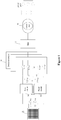
- a direct current side of a five-level inverter 10 is connected to a photovoltaic array 20 and configured to receive a direct current PV input voltage.
- An output voltage from a grid side of the five-level inverter 10 is filtered by a filter 30, step up by a transformer 40 and then transmitted to a power grid.
- the PV input voltage is applied across a positive electrode of a capacitor C1 and a negative electrode of a capacitor C2, voltage applied across C1 is VIPos and voltage applied across C2 is VINeg.
- the PV input voltage is step up by two Boost circuits, then is applied across a positive electrode of a bus capacitor C3 and a negative electrode of a bus capacitor C4, and voltage applied across C3 is V2Pos and voltage applied across C4 is V2Neg.
- the five-level inverter 10 alternately outputs levels +V1Pos (i.e., +1), -V1Neg (i.e., -1), +V2Pos (i.e., +2), -V2Neg (i.e., -2) and a zero level corresponding to the middle point of the DC bus.
- the operation mode of the five-level inverter 10 is switched automatically from a five-level operation mode to a three-level operation mode.
- the bus voltage is high and the output voltage level of the grid side inverter is reduced, power loss of switching devices S1Pos, S1Neg and S0 increases significantly, and a junction temperature of the switching devices is higher, over-temperature protection for the switching devices may be triggered and service lives of the switching devices are reduced greatly.
- Patent application publication No. CN103023363A discloses a five-level inverter comprising a positive Boost circuit, a negative Boost circuit and an inversion circuit.
- the inversion circuit comprises a pair of input branches, a pair of positive afterflow branches and a pair of inversion vertical bridge arm input branches.
- a seventh switch tube crosses over any two branches of the positive input branch, the positive afterflow branch and the inversion vertical bridge arm positive input branch, and an eighth switch tube crosses over any two branches of the negative input branch, the negative afterflow branch and the inversion vertical bridge arm negative input branch.
- At least one branch of the two branches crossed over by the seventh switch tube does not belong to the same pair of branches as any branch of the two branches crossed over by the eighth switch tube, and the same pair of branches is any of a pair of input branches, a pair of afterflow branches and a pair of inversion vertical bridge arm input branches. Switching loss of a power device and onstate loss of a main power device are effectively reduced, and the efficiency of a system is improved.
- a method for switching an operation mode of a five-level inverter and device for switching an operation mode of a five-level inverter are provided according to the present disclosure, to reduce a junction temperature of the switching devices still operating after the operation mode of the five-level inverter is switched from a five-level operation mode to a three-level operation mode, thereby preventing shutting down of the five-level inverter due to triggering of over-temperature protection for the switching devices and prolonging service lives of the switching devices.
- a method for switching an operation mode of a five-level inverter comprising a first switching device, a second switching device, a third switching device, a fourth switching device and a fifth switching device is provided, which includes:
- the method for switching an operation mode of a five-level inverter which further includes:
- the junction temperature of the switching device operating in the positive half-period of the output voltage of each single-phase bridge and in the first three-level operation mode exceeding the first preset value may indicate that a current value of at least one of the following variants: the junction temperature of the first switching device, a substrate temperature of the first switching device, a radiator temperature of the first switching device, an I 2 t calculation value of the first switching device and an operation duration of the first switching device is greater than a threshold of the at least one of the variants;
- the junction temperature of the switching device operating in the positive half-period of the output voltage of each single-phase bridge and in the second three-level operation mode exceeding the second preset value may indicate that a current value of at least one of the following variants: the junction temperature of the second switching device, the substrate temperature of the second switching device, the radiator temperature of the second switching device, the I 2 t calculation value of the second switching device and the operation duration of the second switching device is greater than a threshold of the at least one of the variants; the junction temperature of the switching
- a device comprising a five-level inverter comprising a first switching device, a second switching device, a third switching device, a fourth switching device and a fifth switching device is provided, which includes:
- the device for switching an operation mode of a five-level inverter which includes:
- the operation mode of the five-level inverter is controlled to be switched between the two three-level operation modes, and the switching devices corresponding to the first operation mode and the switching devices corresponding to the second operation mode operate alternately, such that power loss is shared by two groups of switching devices, thereby reducing a maximum junction temperature of each group of switching devices, reducing a heat-dissipation cost of the switching devices, prolonging service lives of the switching devices and improving the operation reliability of the five-level inverter.
- a method for switching an operation mode of a five-level inverter is disclosed according to an embodiment of the present disclosure, to reduce a junction temperature of a switching device still operating after the operation mode of the five-level inverter is switched from a five-level operation mode to a three-level operation mode, thereby preventing shutting down of the five-level inverter due to triggering of over-temperature protection for the switching device and prolonging service lives of the switching device.
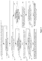
- the method includes step 200 to step 205 hereinafter.
- a first three-level operation mode is determined as a three-level operation mode of the five-level inverter to be switched to from a five-level operation mode in a case that a PV input voltage is higher than a bridge line-line voltage command value of the five-level inverter required when the five-level inverter is connected to a power grid.
- the five-level inverter has two three-level operation modes.
- step 201 it is determined whether the operation mode of the five-level inverter is switched to the first three-level operation mode; and if the operation mode is switched to the first three-level operation mode, the method proceeds to step 202; otherwise, the method returns to step 201.
- step 202 it is determined whether a junction temperature of a switching device operating in the first three-level operation mode exceeds a first preset value; and if the junction temperature exceeds the first preset value, the method proceeds to step 203; otherwise, the method returns to step 202.
- step 203 the operation mode of the five-level inverter is switched from the first three-level operation mode to a second three-level operation mode.
- step 204 it is determined whether the junction temperature of a switching device operating in the second three-level operation mode exceeds a second preset value; and if the junction temperature exceeds the second preset value, the method proceeds to step 205; otherwise, the method returns to step 204.
- step 205 the operation mode of the five-level inverter is switched from the second three-level operation mode to the first three-level operation mode, and then the method returns to step 202.
- a five-level inverter 10 operates in a five-level operation mode, i.e., the five-level inverter 10 alternately outputs five levels +1, -1, +2, -2 and 0 in different combinations of switching states of switching devices, and values of the five levels are respectively +V1Pos, -VINeg, +V2Pos, -V2Neg and 0.
- S2Pos indicates a first switching device, the level +2 is outputted when the first switching device is switched on;
- S2Neg indicates a second switching device, the level -2 is outputted when the second switching device is switched on;
- SO indicates a third switching device, the level 0 is outputted when the third switching device is switched on;
- S1Pos indicates a fourth switching device, the level +1 is outputted when the fourth switching device is switched on;
- S1Neg indicates a fifth switching device, the level -1 is outputted when the fifth switching device is switched on.
- the operation mode of the five-level inverter 10 is automatically switched from a five-level operation mode to a three-level operation mode.
- the five-level inverter 10 has two three-level operation modes: one three-level operation mode refers to an operation mode in which S1Pos and S1Neg are cut off and S0, S2Pos and S2Neg are controlled to operate alternatively; and another three-level operation mode refers to an operation mode in which S2Pos and S2Neg are cut off and S0, S1Pos and S1Neg are controlled to operate alternately.
- the operation mode of the five-level inverter 10 is controlled to be switched between the two three-level operation modes, thereby avoiding a higher junction temperature of S2Pos/S2Neg in a case that S2Pos/S2Neg operates for a long period of time in the three-level operation mode in which S0, S2Pos and S2Neg are controlled to operate alternatively or a higher junction temperature of S1Pos/S1Neg in a case that S1Pos/S1Neg operates for a long period of time in the three-level operation mode in which S0, S1Pos and S1Neg are controlled to operate alternately.
- a first three-level operation mode is defined as the mode in which S2Pos, S2Neg and SO operate alternately
- a second three-level operation mode is defined as the mode in which S1Pos, S1Neg and S0 operate alternately.
- I 2 t i.e., heat accumulation
- I 2 t indicates an integration of a square of a current per unit time and indicates heat quantity generated in a unit conductor physically.
- the operation mode of the five-level inverter 10 is controlled to be switched between the two three-level operation modes, and the switching devices corresponding to the first operation mode and the switching devices corresponding to the second operation mode operate alternately, such that power loss is shared by two groups of switching devices, thereby reducing a maximum junction temperature of each group of switching devices, reducing a heat-dissipation cost of the switching devices, prolonging service lives of the switching devices and improving the operation reliability of the five-level inverter 10.
- FIG. 3 another method for switching an operation mode of a five-level inverter is further disclosed according to an embodiment of the present disclosure, to reduce a junction temperature of a switching device still operating after the operation mode of the five-level inverter is switched from a five-level operation mode to a three-level operation mode.
- the method includes step 300 to step 310 hereinafter.
- a first three-level operation mode is determined as a three-level operation mode of the five-level inverter to be switched to from a five-level operation mode in a case that a PV input voltage is higher than a bridge line-line voltage command value of the five-level inverter required when the five-level inverter is connected to a power grid.
- the five-level inverter has two three-level operation modes.
- step 301 it is determined whether the operation mode of the five-level inverter is switched to the first three-level operation mode; and if the operation mode is switched to the first three-level operation mode, the method proceeds to step 302; otherwise, the method returns to step 301.
- step 302 it is determined whether an output voltage of each single-phase bridge of the five-level inverter is in a positive half-period; and if the output voltage is in the positive half-period, the method proceeds to step 303; otherwise, the method proceeds to step 307.
- step 303 it is determined whether a junction temperature of a switching device operating in the first three-level operation mode exceeds a third preset value; and if the junction temperature exceeds the third preset value, the method proceeds to step 304; otherwise, the method returns to step 303.
- step 304 the operation mode of the five-level inverter is switched from the first three-level operation mode to a second three-level operation mode.
- step 305 it is determined whether the junction temperature of a switching device operating in the second three-level operation mode exceeds a fourth preset value; and if the junction temperature exceeds the fourth preset value, the method proceeds to step 306; otherwise, the method returns to step 305.
- step 306 the operation mode of the five-level inverter is switched from the second three-level operation mode to the first three-level operation mode, and then the method returns to step 302.
- step 307 it is determined whether the junction temperature of the switching device operating in the first three-level operation mode exceeds a fifth preset value; and if the junction temperature exceeds the fifth preset value, the method proceeds to step 308; otherwise, the method returns to step 307.
- step 308 the operation mode of the five-level inverter is switched from the first three-level operation mode to the second three-level operation mode.
- step 309 it is determined whether the junction temperature of the switching device operating in the second three-level operation mode exceeds a sixth preset value; and if the junction temperature exceeds the sixth preset value, the method proceeds to step 310; otherwise, the method returns to step 309.
- step 310 the operation mode of the five-level inverter is switched from the second three-level operation mode to the first three-level operation mode, and then the method returns to step 302.
- Step 302 As compared with a three-level operation mode in which S1Pos, S1Neg and SO operate alternatively, the junction temperature of a switching device operating in a three-level operation mode in which S2Pos, S2Neg and SO operate alternatively is lower, hence the latter operation mode is selected as a first three-level operation mode.
- Step 302, step 303, step 305, step 307 and step 309 indicate switching conditions to be met in a case that the operation mode of the five-level inverter is switched from one of the two three-level operation mode to the other of the two three-level operation mode. Specifically,
- the operation mode of the five-level inverter 10 is switched between the two three-level operation modes in the positive half-period or the negative half-period of the output voltage.
- the junction temperature of only one switching device needs to be considered in each time period, thereby facilitating calculation.
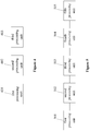
- a device for switching an operation mode of a five-level inverter is further disclosed according to an embodiment of the present disclosure, to reduce a junction temperature of a switching device still operating after the operation mode of the five-level inverter is switched from a five-level operation mode to a three-level operation mode.
- the device includes a first processing unit 401, a second processing unit 402 and a third processing unit 403.
- the first processing unit 401 is configured to determine a first three-level operation mode as a three-level operation mode of the five-level inverter to be switched to from a five-level operation mode in a case that a PV input voltage is higher than a bridge line-line voltage command value of the five-level inverter required when the five-level inverter is connected to a power grid.
- the five-level inverter has two three-level operation modes.
- the second processing unit 402 is configured to switch, after the operation mode of the five-level inverter is switched to the first three-level operation mode, the operation mode of the five-level inverter from the first three-level operation mode to a second three-level operation mode in a case that a junction temperature of a switching device operating in the first three-level operation mode exceeds a first preset value.
- the third processing unit 403 is configured to switch the operation mode of the five-level inverter from the second three-level operation mode to the first three-level operation mode in a case that the junction temperature of a switching device operating in the second three-level operation mode exceeds a second preset value.
- the first three-level operation mode is defined as an operation mode in which S2Pos, S2Neg and SO operate alternately
- the second three-level operation mode is defined as an operation mode in which S1Pos, S1Neg and SO operate alternately.
- the first processing unit 501 is configured to determine a first three-level operation mode as a three-level operation mode of the five-level inverter to be switched to from a five-level operation mode in a case that a PV input voltage is higher than a bridge line-line voltage command value of the five-level inverter required when the five-level inverter is connected to a power grid.
- the five-level inverter has two three-level operation modes.
- the second processing unit 502 is configured to switch, after the operation mode of the five-level inverter is switched to the first three-level operation mode, the operation mode of the five-level inverter from the first three-level operation mode to a second three-level operation mode in a case that a junction temperature of a switching device operating in a positive half-period of an output voltage of each single-phase bridge and in the first three-level operation mode exceeds a third preset value.
- the third processing unit 503 is configured to switch the operation mode of the five-level inverter from the second three-level operation mode to the first three-level operation mode in a case that the junction temperature of a switching device operating in the positive half-period of the output voltage of each single-phase bridge and in the second three-level operation mode exceeds a fourth preset value.
- the fourth processing unit 504 is configured to switch the operation mode of the five-level inverter from the first three-level operation mode to a second three-level operation mode in a case that the junction temperature of a switching device operating in a negative half-period of the output voltage of each single-phase bridge and in the first three-level operation mode exceeds a fifth preset value.
- the fifth processing unit 505 is configured to switch the operation mode of the five-level inverter from the second three-level operation mode to the first three-level operation mode in a case that the junction temperature of a switching device operating in the negative half-period of the output voltage of each single-phase bridge and in the second three-level operation mode exceeds a sixth preset value.
- the first three-level operation mode is still defined as an operation mode in which S2Pos, S2Neg and SO operate alternately
- the second three-level mode is defined as an operation mode in which S1Pos, S1Neg and SO operate alternately.
- the operation mode of the five-level inverter is controlled to be switched between the two three-level operation modes, and the switching devices corresponding to the first operation mode and the switching devices corresponding to the second operation mode operate alternately, such that power loss is shared by two groups of switching devices, thereby reducing a maximum junction temperature of each group of switching devices, reducing a heat-dissipation cost of the switching devices, prolonging service lives of the switching devices and improving the operation reliability of the five-level inverter.
Landscapes
- Engineering & Computer Science (AREA)
- Power Engineering (AREA)
- Inverter Devices (AREA)
Claims (6)
- Procédé pour commuter un mode de fonctionnement d'un onduleur à cinq niveaux (10) comprenant un premier dispositif de commutation (S2Pos), un deuxième dispositif de commutation (S2Neg), un troisième dispositif de commutation (S0), un quatrième dispositif de commutation (S1Pos) et un cinquième dispositif de commutation (S1Neg),
dans lequel l'onduleur à cinq niveaux (10) sort en alternance cinq niveaux +1, -1, +2, -2 et 0 dans différentes combinaisons d'états de commutation des dispositifs de commutation, dans lequel le niveau +1 est sorti lorsque le quatrième dispositif de commutation (S1Pos) est activé ; le niveau -1 est sorti lorsque le cinquième dispositif de commutation (S1Neg) est activé ; le niveau +2 est sorti lorsque le premier dispositif de commutation (S2Pos) est activé ; le niveau -2 est sorti lorsque le deuxième dispositif de commutation (S2Neg) est activé ; et le niveau 0 est sorti lorsque le troisième dispositif de commutation (SO) est activé ; le procédé comprenant :
la détermination (200) d'un premier mode de fonctionnement à trois niveaux en tant que mode de fonctionnement à trois niveaux de l'onduleur à cinq niveaux (10) pour y être commuté à partir d'un mode de fonctionnement à cinq niveaux dans le cas où une tension d'entrée PV serait supérieure à une valeur de commande de tension de ligne de pont de l'onduleur à cinq niveaux (10) requise lorsque l'onduleur à cinq niveaux (10) est connecté à un réseau électrique, caractérisé en ce que l'onduleur à cinq niveaux (10) présente deux modes de fonctionnement à trois niveaux ; et en outre caractérisé par :sla commutation (203), après que le mode de fonctionnement de l'onduleur à cinq niveaux (10) est commuté au premier mode de fonctionnement à trois niveaux, du mode de fonctionnement de l'onduleur à cinq niveaux (10) depuis le premier mode de fonctionnement à trois niveaux à un deuxième mode de fonctionnement à trois niveaux dans le cas où une température de jonction d'un dispositif de commutation fonctionnant dans le premier mode de fonctionnement à trois niveaux dépasserait une première valeur prédéfinie ; etla commutation (205) du mode de fonctionnement de l'onduleur à cinq niveaux (10) depuis le deuxième mode de fonctionnement à trois niveaux au premier mode de fonctionnement à trois niveaux dans le cas où la température de jonction d'un dispositif de commutation fonctionnant dans le deuxième le mode de fonctionnement à trois niveaux dépasserait une deuxième valeur prédéfinie ;dans lequel le premier mode de fonctionnement à trois niveaux se réfère à un mode de fonctionnement dans lequel le premier dispositif de commutation (S2Pos), le deuxième dispositif de commutation (S2Neg) et le troisième dispositif de commutation (S0) sont commandés de manière à fonctionner en alternance, et le quatrième dispositif de commutation (S1Pos) et le cinquième dispositif de commutation (S1Neg) sont inactivés ; et le deuxième mode de fonctionnement à trois niveaux se réfère à un mode de fonctionnement dans lequel le quatrième dispositif de commutation (S1Pos), le cinquième dispositif de commutation (S1Neg) et le troisième dispositif de commutation (S0) sont commandés de manière à fonctionner en alternance, et le premier dispositif de commutation (S2Pos) et le deuxième dispositif de commutation (S2Neg) sont inactivés. - Procédé selon la revendication 1, dans lequel
la température de jonction du dispositif de commutation fonctionnant dans le premier mode de fonctionnement à trois niveaux dépassant la première valeur prédéfinie indique que la valeur d'au moins une des variantes suivantes : la température de jonction du premier dispositif de commutation (S2Pos) ou du deuxième dispositif de commutation (S2Neg), une température de substrat du premier dispositif de commutation (S2Pos) ou du deuxième dispositif de commutation (S2Neg), une température de radiateur du premier dispositif de commutation (S2Pos) ou du deuxième dispositif de commutation (S2Neg), une valeur de calcul I2t du premier dispositif de commutation (S2Pos) ou du deuxième dispositif de commutation (S2Neg) et une durée de fonctionnement du premier dispositif de commutation (S2Pos) ou du deuxième dispositif de commutation (S2Neg) est supérieure à un seuil ; et
la température de jonction du dispositif de commutation fonctionnant dans le deuxième mode de fonctionnement à trois niveaux dépassant la deuxième valeur prédéfinie indique que la valeur d'au moins une des variantes suivantes :
la température de jonction du quatrième dispositif de commutation (S1Pos) ou du cinquième dispositif de commutation (S1Neg), la température de substrat du quatrième dispositif de commutation (S1Pos) ou du cinquième dispositif de commutation (S1Neg), la température de radiateur du quatrième dispositif de commutation (S1Pos) ou du cinquième dispositif de commutation (S1Neg), la valeur de calcul I2t du quatrième dispositif de commutation (S1Pos) ou du cinquième dispositif de commutation (S1Neg) et la durée de fonctionnement du du quatrième dispositif de commutation (S1Pos) ou du cinquième dispositif de commutation (S1Neg) est supérieure à un seuil. - Procédé selon la revendication 1, dans lequel :la commutation du premier mode de fonctionnement à trois niveaux au deuxième mode de fonctionnement à trois niveaux a lieu dans le cas où une température de jonction d'un dispositif de commutation respectif fonctionnant dans une demi-période positive d'une tension de sortie de chaque pont monophasé et dans le premier mode de fonctionnement à trois niveaux dépasserait la première valeur prédéfinie, et la commutation (306) du mode de fonctionnement de l'onduleur à cinq niveaux (10) du deuxième mode de fonctionnement à trois niveaux au premier mode de fonctionnement à trois niveaux a lieu dans le cas où la température de jonction d'un dispositif de commutation respectif fonctionnant dans la demi-période positive de la tension de sortie de chaque pont monophasé et dans le deuxième mode de fonctionnement à trois niveaux dépasserait la deuxième valeur prédéfinie ; etla commutation (308) du mode de fonctionnement de l'onduleur à cinq niveaux (10) du premier mode de fonctionnement à trois niveaux au deuxième mode de fonctionnement à trois niveaux a lieu dans le cas où la température de jonction d'un dispositif de commutation respectif fonctionnant dans une demi-période négative de la tension de sortie de chaque pont monophasé et dans le premier mode de fonctionnement à trois niveaux dépasserait une troisième valeur prédéfinie, et la commutation (310) du mode de fonctionnement de l'onduleur à cinq niveaux (10) du deuxième mode de fonctionnement à trois niveaux au premier mode de fonctionnement à trois niveaux a lieu dans le cas où la température de jonction d'un dispositif de commutation respectif fonctionnant dans la demi-période négative de la tension de sortie de chaque pont monophasé et dans le deuxième mode de fonctionnement à trois niveaux dépasserait une quatrième valeur prédéfinie.
- Procédé selon la revendication 3, dans lequel
la température de jonction du dispositif de commutation fonctionnant dans la demi-période positive de la tension de sortie de chaque pont monophasé et dans le premier mode de fonctionnement à trois niveaux dépassant la première valeur prédéfinie indique que la valeur d'au moins une des variantes suivantes : la température de jonction du premier dispositif de commutation (S2Pos), une température de substrat du premier dispositif de commutation (S2Pos), une température de radiateur du premier dispositif de commutation (S2Pos), une valeur de calcul I2t du premier dispositif de commutation (S2Pos) et une durée de fonctionnement du premier dispositif de commutation (S2Pos) est supérieure à un seuil ;
la température de jonction du dispositif de commutation fonctionnant dans la demi-période positive de la tension de sortie de chaque pont monophasé et dans le deuxième mode de fonctionnement à trois niveaux dépassant la deuxième valeur prédéfinie indique que la valeur d'au moins une des variantes suivantes : la température de jonction du deuxième dispositif de commutation (S2Neg), la température de substrat du deuxième dispositif de commutation (S2Neg), la température de radiateur du deuxième dispositif de commutation (S2Neg), la valeur de calcul I2t du deuxième dispositif de commutation (S2Neg) et la durée de fonctionnement du deuxième dispositif de commutation (S2Neg) est supérieure à un seuil ;
la température de jonction du dispositif de commutation fonctionnant dans la demi-période négative de la tension de sortie de chaque pont monophasé et dans le premier mode de fonctionnement à trois niveaux dépassant la troisième valeur prédéfinie indique que la valeur d'au moins une des variantes suivantes : la température de jonction du quatrième dispositif de commutation (S1Pos), la température de substrat du quatrième dispositif de commutation (S1Pos), la température de radiateur du quatrième dispositif de commutation (S1 Pos), la valeur de calcul I2t du quatrième dispositif de commutation (S1Pos) et la durée de fonctionnement du quatrième dispositif de commutation (S1 Pos) est supérieure à un seuil ; et
la température de jonction du dispositif de commutation fonctionnant dans la demi-période négative de la tension de sortie de chaque pont monophasé et dans le deuxième mode de fonctionnement à trois niveaux dépassant la quatrième valeur prédéfinie indique que la valeur d'au moins une des variantes suivantes : la température de jonction du cinquième dispositif de commutation (S1Neg), la température de substrat du cinquième dispositif de commutation (S1Neg), la température de radiateur du cinquième dispositif de commutation (S1Neg), la valeur de calcul I2t du cinquième dispositif de commutation (S1Neg) et la durée de fonctionnement du cinquième dispositif de commutation (S1Neg) est supérieure à un seuil. - Dispositif comprenant un onduleur à cinq niveaux (10) comprenant un premier dispositif de commutation (S2Pos), un deuxième dispositif de commutation (S2Neg), un troisième dispositif de commutation (S0), un quatrième dispositif de commutation (S1Pos) et un cinquième dispositif de commutation (S1Neg),
l'onduleur à cinq niveaux (10) étant configuré pour sortir en alternance cinq niveaux +1, -1, +2, -2 et 0 dans différentes combinaisons d'états de commutation des dispositifs de commutation, dans lequel le niveau +1 est sorti lorsque le quatrième dispositif de commutation (SI Pos) est activé ; le niveau -1 est sorti lorsque le cinquième dispositif de commutation (SINeg) est activé ; le niveau +2 est sorti lorsque le premier dispositif de commutation (S2Pos) est activé ; le niveau -2 est sorti lorsque le deuxième dispositif de commutation (S2Neg) est activé ; et le niveau 0 est sorti lorsque le troisième dispositif de commutation (SO) est activé ; le dispositif comprenant en outre :une première unité de traitement (401) configurée pour déterminer un premier mode de fonctionnement à trois niveaux en tant que mode de fonctionnement à trois niveaux de l'onduleur à cinq niveaux (10) pour y être commuté à partir d'un mode de fonctionnement à cinq niveaux dans le cas où une tension d'entrée PV serait supérieure à un valeur de commande de tension de ligne de pont de l'onduleur à cinq niveaux (10) requise lorsque l'onduleur à cinq niveaux (10) est connecté à un réseau électrique ; caractérisé en ce que l'onduleur à cinq niveaux (10) présente deux modes de fonctionnement à trois niveaux ; et une deuxième unité de traitement (402) configurée pour commuter, après que le mode de fonctionnement de l'onduleur à cinq niveaux (10) est commuté vers le premier mode de fonctionnement à trois niveaux, le mode de fonctionnement de l'onduleur à cinq niveaux (10) du premier mode de fonctionnement à trois niveaux à un deuxième mode de fonctionnement à trois niveaux dans le cas où une température de jonction d'un dispositif de commutation fonctionnant dans le premier mode de fonctionnement à trois niveaux dépasserait une première valeur prédéfinie ; etune troisième unité de traitement (403) configurée pour commuter le mode de fonctionnement de l'onduleur à cinq niveaux (10) du deuxième mode de fonctionnement à trois niveaux au premier mode de fonctionnement à trois niveaux dans le cas où la température de jonction d'un dispositif de commutation fonctionnant dans le deuxième mode de fonctionnement à trois niveaux dépasserait une deuxième valeur prédéfinie ;dans lequel le premier mode de fonctionnement à trois niveaux se réfère à un mode de fonctionnement dans lequel le premier dispositif de commutation (S2Pos), le deuxième dispositif de commutation (S2Neg) et le troisième dispositif de commutation (S0) sont commandés de manière à fonctionner en alternance, et le quatrième dispositif de commutation (S1Pos) et le cinquième dispositif de commutation (S1Neg) sont inactivés ; et le deuxième mode de fonctionnement à trois niveaux se réfère à un mode de fonctionnement dans lequel le quatrième dispositif de commutation (S1Pos), le cinquième dispositif de commutation (S1Neg) et le troisième dispositif de commutation (S0) sont commandés de manière à fonctionner en alternance, et le premier dispositif de commutation (S2Pos) et le deuxième dispositif de commutation (S2Neg) sont inactivés. - Dispositif selon la revendication 5, dans lequel
la deuxième unité de traitement (502) est en outre configurée pour commuter le mode de fonctionnement de l'onduleur à cinq niveaux (10) du premier mode de fonctionnement à trois niveaux au deuxième mode de fonctionnement à trois niveaux dans le cas où la température de jonction d'un dispositif de commutation respectif fonctionnant dans une demi-période positive d'une tension de sortie de chaque pont monophasé et dans le premier mode de fonctionnement à trois niveaux dépasserait la première valeur prédéfinie ;
la troisième unité de traitement (503) est en outre configurée pour commuter le mode de fonctionnement de l'onduleur à cinq niveaux (10) du deuxième mode de fonctionnement à trois niveaux au premier mode de fonctionnement à trois niveaux dans le cas où la température de jonction d'un dispositif de commutation respectif fonctionnant dans la demi-période positive de la tension de sortie de chaque pont monophasé et dans le deuxième mode de fonctionnement à trois niveaux dépasserait la deuxième valeur prédéfinie ;
le dispositif comprend en outre une quatrième unité de traitement (504) configurée pour commuter le mode de fonctionnement de l'onduleur à cinq niveaux (10) du premier mode de fonctionnement à trois niveaux au deuxième mode de fonctionnement à trois niveaux dans le cas où la température de jonction d'un dispositif de commutation respectif fonctionnant dans une demi-période négative de la tension de sortie de chaque pont monophasé et dans le premier mode de fonctionnement à trois niveaux dépasserait une cinquième valeur prédéfinie ; et
le dispositif comprend en outre une cinquième unité de traitement (505) configurée pour commuter le mode de fonctionnement de l'onduleur à cinq niveaux (10) du deuxième mode de fonctionnement à trois niveaux au premier mode de fonctionnement à trois niveaux dans le cas où la température de jonction d'un dispositif de commutation respectif fonctionnant dans la demi-période négative de la tension de sortie de chaque pont monophasé et dans le deuxième mode de fonctionnement à trois niveaux dépasserait une quatrième valeur prédéfinie.
Applications Claiming Priority (1)
| Application Number | Priority Date | Filing Date | Title |
|---|---|---|---|
| CN201410795320.0A CN104410307B (zh) | 2014-12-18 | 2014-12-18 | 五电平逆变器的工作模式切换方法和装置 |
Publications (3)
| Publication Number | Publication Date |
|---|---|
| EP3035509A2 EP3035509A2 (fr) | 2016-06-22 |
| EP3035509A3 EP3035509A3 (fr) | 2016-08-03 |
| EP3035509B1 true EP3035509B1 (fr) | 2021-01-27 |
Family
ID=52647910
Family Applications (1)
| Application Number | Title | Priority Date | Filing Date |
|---|---|---|---|
| EP15193952.7A Active EP3035509B1 (fr) | 2014-12-18 | 2015-11-10 | Procédé et dispositif pour la commutation de mode de fonctionnement d'un onduleur à cinq niveaux |
Country Status (4)
| Country | Link |
|---|---|
| US (1) | US9712083B2 (fr) |
| EP (1) | EP3035509B1 (fr) |
| JP (1) | JP6141944B2 (fr) |
| CN (1) | CN104410307B (fr) |
Families Citing this family (5)
| Publication number | Priority date | Publication date | Assignee | Title |
|---|---|---|---|---|
| CN104410307B (zh) * | 2014-12-18 | 2017-01-18 | 阳光电源股份有限公司 | 五电平逆变器的工作模式切换方法和装置 |
| CN104538987B (zh) * | 2014-12-31 | 2017-01-11 | 阳光电源股份有限公司 | 一种光伏逆变器交流侧并联的控制方法及系统 |
| US11843325B2 (en) * | 2020-08-24 | 2023-12-12 | General Electric Company | Crowbar module for an active neutral point clamped power conversion assembly |
| CN113783234B (zh) * | 2021-08-24 | 2023-10-31 | 华北电力大学(保定) | 一种净增发电量最大化的光伏发电pv配置和功率限值优化方法 |
| CN115065223B (zh) * | 2022-08-18 | 2022-11-29 | 杭州飞仕得科技有限公司 | 一种有源钳位三电平电路的优化控制方法和装置 |
Family Cites Families (16)
| Publication number | Priority date | Publication date | Assignee | Title |
|---|---|---|---|---|
| JP2003153588A (ja) | 2001-11-09 | 2003-05-23 | Nissan Motor Co Ltd | モータ駆動装置 |
| US8228695B2 (en) * | 2009-11-16 | 2012-07-24 | General Electric Company | Multilevel converter operation |
| JP2011109789A (ja) | 2009-11-17 | 2011-06-02 | Fuji Electric Holdings Co Ltd | 電力変換装置 |
| WO2012025978A1 (fr) | 2010-08-23 | 2012-03-01 | 東芝三菱電機産業システム株式会社 | Dispositif de conversion d'électricité |
| EP2590312A1 (fr) * | 2011-11-04 | 2013-05-08 | Alstom Technology Ltd | Convertisseur de source de tension avec topologie clampée en neutre modifiée et procédé de fonctionnement d'un tel convertisseur |
| US9413268B2 (en) * | 2012-05-10 | 2016-08-09 | Futurewei Technologies, Inc. | Multilevel inverter device and method |
| JP5626293B2 (ja) | 2012-08-29 | 2014-11-19 | 株式会社村田製作所 | インバータ装置 |
| JP6075024B2 (ja) * | 2012-11-19 | 2017-02-08 | 富士電機株式会社 | マルチレベルインバータ |
| CN103023363B (zh) * | 2012-11-26 | 2015-04-08 | 华为技术有限公司 | 一种五电平逆变器 |
| JP6093479B2 (ja) * | 2013-12-04 | 2017-03-08 | サングロー パワー サプライ カンパニー リミテッド | 5レベルインバータ |
| CN103983891B (zh) * | 2014-05-30 | 2018-10-09 | 台达电子企业管理(上海)有限公司 | 逆变器电路的短路故障检测装置及方法 |
| CN104270027B (zh) * | 2014-10-23 | 2017-06-13 | 阳光电源股份有限公司 | 一种多电平逆变器pwm脉冲生成方法及装置 |
| CN104362843B (zh) * | 2014-10-24 | 2017-06-13 | 阳光电源股份有限公司 | 并联逆变系统及其停机控制方法和停机控制装置 |
| CN104393778B (zh) * | 2014-12-18 | 2017-01-18 | 阳光电源股份有限公司 | 五电平逆变器调制方法、装置以及光伏系统 |
| CN104410307B (zh) * | 2014-12-18 | 2017-01-18 | 阳光电源股份有限公司 | 五电平逆变器的工作模式切换方法和装置 |
| CN104538987B (zh) * | 2014-12-31 | 2017-01-11 | 阳光电源股份有限公司 | 一种光伏逆变器交流侧并联的控制方法及系统 |
-
2014
- 2014-12-18 CN CN201410795320.0A patent/CN104410307B/zh active Active
-
2015
- 2015-11-10 EP EP15193952.7A patent/EP3035509B1/fr active Active
- 2015-11-11 US US14/938,228 patent/US9712083B2/en active Active
- 2015-11-19 JP JP2015226899A patent/JP6141944B2/ja active Active
Non-Patent Citations (1)
| Title |
|---|
| None * |
Also Published As
| Publication number | Publication date |
|---|---|
| JP2016119832A (ja) | 2016-06-30 |
| CN104410307A (zh) | 2015-03-11 |
| CN104410307B (zh) | 2017-01-18 |
| JP6141944B2 (ja) | 2017-06-07 |
| EP3035509A3 (fr) | 2016-08-03 |
| US9712083B2 (en) | 2017-07-18 |
| EP3035509A2 (fr) | 2016-06-22 |
| US20160181946A1 (en) | 2016-06-23 |
Similar Documents
| Publication | Publication Date | Title |
|---|---|---|
| US11201565B2 (en) | Conversion circuit, control method, and power supply device | |
| EP3035509B1 (fr) | Procédé et dispositif pour la commutation de mode de fonctionnement d'un onduleur à cinq niveaux | |
| CN102522911B (zh) | 逆变装置及应用其的太阳能光伏并网系统 | |
| CN206775459U (zh) | 一种光伏组件的关断装置及光伏组件关断系统 | |
| EP3171476A1 (fr) | Système de mmc-ccht, et dispositif d'isolation du côté à courant continu et son procédé d'isolation | |
| US11139733B2 (en) | Modular multilevel converter sub-module having DC fault current blocking function and method of controlling the same | |
| WO2021103674A1 (fr) | Procédé et appareil de détection de court-circuit pour onduleur, et onduleur | |
| US9923481B2 (en) | Photovoltaic system and method for controlling the same | |
| CN103944148A (zh) | 一种t型三电平逆变器的保护方法、装置及逆变电路 | |
| CN104638615A (zh) | 具有直流故障隔离能力的模块化多电平换流器及其子模块 | |
| US9590489B2 (en) | Converter | |
| WO2016008093A1 (fr) | Procédé de sortie et de commutation de conversion optimale d'énergie centralisé et son application | |
| CN111835221A (zh) | 一种dc/ac电力变换装置 | |
| WO2021017704A1 (fr) | Dispositif onduleur et système d'alimentation électrique | |
| CN203368361U (zh) | 一种多路直流输入的光伏逆变器 | |
| WO2024045509A1 (fr) | Optimiseur photovoltaïque parallèle | |
| CN110249497A (zh) | 母线电压的调节方法及相关设备 | |
| EP3035510A2 (fr) | Procédé et dispositif permettant de moduler un onduleur à cinq niveaux et système photovoltaïque | |
| CN106505903A (zh) | 一种三相四桥臂逆变系统 | |
| CN106357132B (zh) | 一种三相三线整流电路的控制方法及设备 | |
| CN104993683A (zh) | 模块化多电平换流器子模块电路 | |
| CN204906215U (zh) | 具有直流侧故障阻断能力的mmc子模块电路 | |
| CN108011389A (zh) | 一种复合型直流输电设备 | |
| CN109672329B (zh) | 一种模块化系统的保护电路 | |
| CN112736861A (zh) | 一种直流能量路由器及其故障隔离方法 |
Legal Events
| Date | Code | Title | Description |
|---|---|---|---|
| PUAI | Public reference made under article 153(3) epc to a published international application that has entered the european phase |
Free format text: ORIGINAL CODE: 0009012 |
|
| AK | Designated contracting states |
Kind code of ref document: A2 Designated state(s): AL AT BE BG CH CY CZ DE DK EE ES FI FR GB GR HR HU IE IS IT LI LT LU LV MC MK MT NL NO PL PT RO RS SE SI SK SM TR |
|
| AX | Request for extension of the european patent |
Extension state: BA ME |
|
| PUAL | Search report despatched |
Free format text: ORIGINAL CODE: 0009013 |
|
| AK | Designated contracting states |
Kind code of ref document: A3 Designated state(s): AL AT BE BG CH CY CZ DE DK EE ES FI FR GB GR HR HU IE IS IT LI LT LU LV MC MK MT NL NO PL PT RO RS SE SI SK SM TR |
|
| AX | Request for extension of the european patent |
Extension state: BA ME |
|
| RIC1 | Information provided on ipc code assigned before grant |
Ipc: H02M 3/00 20060101ALN20160627BHEP Ipc: H02M 1/32 20070101ALN20160627BHEP Ipc: H02M 7/487 20070101AFI20160627BHEP |
|
| STAA | Information on the status of an ep patent application or granted ep patent |
Free format text: STATUS: REQUEST FOR EXAMINATION WAS MADE |
|
| 17P | Request for examination filed |
Effective date: 20170203 |
|
| RBV | Designated contracting states (corrected) |
Designated state(s): AL AT BE BG CH CY CZ DE DK EE ES FI FR GB GR HR HU IE IS IT LI LT LU LV MC MK MT NL NO PL PT RO RS SE SI SK SM TR |
|
| STAA | Information on the status of an ep patent application or granted ep patent |
Free format text: STATUS: EXAMINATION IS IN PROGRESS |
|
| 17Q | First examination report despatched |
Effective date: 20180712 |
|
| REG | Reference to a national code |
Ref country code: DE Ref legal event code: R079 Ref document number: 602015065170 Country of ref document: DE Free format text: PREVIOUS MAIN CLASS: H02M0001000000 Ipc: H02M0007487000 |
|
| RIC1 | Information provided on ipc code assigned before grant |
Ipc: H02M 7/487 20070101AFI20200708BHEP Ipc: H02M 3/00 20060101ALN20200708BHEP Ipc: H02M 1/32 20070101ALN20200708BHEP |
|
| RIC1 | Information provided on ipc code assigned before grant |
Ipc: H02M 7/487 20070101AFI20200721BHEP Ipc: H02M 3/00 20060101ALN20200721BHEP Ipc: H02M 1/32 20070101ALN20200721BHEP |
|
| GRAP | Despatch of communication of intention to grant a patent |
Free format text: ORIGINAL CODE: EPIDOSNIGR1 |
|
| STAA | Information on the status of an ep patent application or granted ep patent |
Free format text: STATUS: GRANT OF PATENT IS INTENDED |
|
| INTG | Intention to grant announced |
Effective date: 20200911 |
|
| GRAS | Grant fee paid |
Free format text: ORIGINAL CODE: EPIDOSNIGR3 |
|
| GRAA | (expected) grant |
Free format text: ORIGINAL CODE: 0009210 |
|
| STAA | Information on the status of an ep patent application or granted ep patent |
Free format text: STATUS: THE PATENT HAS BEEN GRANTED |
|
| AK | Designated contracting states |
Kind code of ref document: B1 Designated state(s): AL AT BE BG CH CY CZ DE DK EE ES FI FR GB GR HR HU IE IS IT LI LT LU LV MC MK MT NL NO PL PT RO RS SE SI SK SM TR |
|
| REG | Reference to a national code |
Ref country code: GB Ref legal event code: FG4D |
|
| REG | Reference to a national code |
Ref country code: CH Ref legal event code: EP |
|
| REG | Reference to a national code |
Ref country code: AT Ref legal event code: REF Ref document number: 1359234 Country of ref document: AT Kind code of ref document: T Effective date: 20210215 |
|
| REG | Reference to a national code |
Ref country code: IE Ref legal event code: FG4D |
|
| REG | Reference to a national code |
Ref country code: DE Ref legal event code: R096 Ref document number: 602015065170 Country of ref document: DE |
|
| REG | Reference to a national code |
Ref country code: NL Ref legal event code: MP Effective date: 20210127 |
|
| REG | Reference to a national code |
Ref country code: LT Ref legal event code: MG9D |
|
| REG | Reference to a national code |
Ref country code: AT Ref legal event code: MK05 Ref document number: 1359234 Country of ref document: AT Kind code of ref document: T Effective date: 20210127 |
|
| PG25 | Lapsed in a contracting state [announced via postgrant information from national office to epo] |
Ref country code: PT Free format text: LAPSE BECAUSE OF FAILURE TO SUBMIT A TRANSLATION OF THE DESCRIPTION OR TO PAY THE FEE WITHIN THE PRESCRIBED TIME-LIMIT Effective date: 20210527 Ref country code: LT Free format text: LAPSE BECAUSE OF FAILURE TO SUBMIT A TRANSLATION OF THE DESCRIPTION OR TO PAY THE FEE WITHIN THE PRESCRIBED TIME-LIMIT Effective date: 20210127 Ref country code: HR Free format text: LAPSE BECAUSE OF FAILURE TO SUBMIT A TRANSLATION OF THE DESCRIPTION OR TO PAY THE FEE WITHIN THE PRESCRIBED TIME-LIMIT Effective date: 20210127 Ref country code: GR Free format text: LAPSE BECAUSE OF FAILURE TO SUBMIT A TRANSLATION OF THE DESCRIPTION OR TO PAY THE FEE WITHIN THE PRESCRIBED TIME-LIMIT Effective date: 20210428 Ref country code: FI Free format text: LAPSE BECAUSE OF FAILURE TO SUBMIT A TRANSLATION OF THE DESCRIPTION OR TO PAY THE FEE WITHIN THE PRESCRIBED TIME-LIMIT Effective date: 20210127 Ref country code: BG Free format text: LAPSE BECAUSE OF FAILURE TO SUBMIT A TRANSLATION OF THE DESCRIPTION OR TO PAY THE FEE WITHIN THE PRESCRIBED TIME-LIMIT Effective date: 20210427 Ref country code: NL Free format text: LAPSE BECAUSE OF FAILURE TO SUBMIT A TRANSLATION OF THE DESCRIPTION OR TO PAY THE FEE WITHIN THE PRESCRIBED TIME-LIMIT Effective date: 20210127 Ref country code: NO Free format text: LAPSE BECAUSE OF FAILURE TO SUBMIT A TRANSLATION OF THE DESCRIPTION OR TO PAY THE FEE WITHIN THE PRESCRIBED TIME-LIMIT Effective date: 20210427 |
|
| PG25 | Lapsed in a contracting state [announced via postgrant information from national office to epo] |
Ref country code: SE Free format text: LAPSE BECAUSE OF FAILURE TO SUBMIT A TRANSLATION OF THE DESCRIPTION OR TO PAY THE FEE WITHIN THE PRESCRIBED TIME-LIMIT Effective date: 20210127 Ref country code: RS Free format text: LAPSE BECAUSE OF FAILURE TO SUBMIT A TRANSLATION OF THE DESCRIPTION OR TO PAY THE FEE WITHIN THE PRESCRIBED TIME-LIMIT Effective date: 20210127 Ref country code: LV Free format text: LAPSE BECAUSE OF FAILURE TO SUBMIT A TRANSLATION OF THE DESCRIPTION OR TO PAY THE FEE WITHIN THE PRESCRIBED TIME-LIMIT Effective date: 20210127 Ref country code: PL Free format text: LAPSE BECAUSE OF FAILURE TO SUBMIT A TRANSLATION OF THE DESCRIPTION OR TO PAY THE FEE WITHIN THE PRESCRIBED TIME-LIMIT Effective date: 20210127 Ref country code: AT Free format text: LAPSE BECAUSE OF FAILURE TO SUBMIT A TRANSLATION OF THE DESCRIPTION OR TO PAY THE FEE WITHIN THE PRESCRIBED TIME-LIMIT Effective date: 20210127 |
|
| PG25 | Lapsed in a contracting state [announced via postgrant information from national office to epo] |
Ref country code: IS Free format text: LAPSE BECAUSE OF FAILURE TO SUBMIT A TRANSLATION OF THE DESCRIPTION OR TO PAY THE FEE WITHIN THE PRESCRIBED TIME-LIMIT Effective date: 20210527 |
|
| REG | Reference to a national code |
Ref country code: DE Ref legal event code: R097 Ref document number: 602015065170 Country of ref document: DE |
|
| PG25 | Lapsed in a contracting state [announced via postgrant information from national office to epo] |
Ref country code: CZ Free format text: LAPSE BECAUSE OF FAILURE TO SUBMIT A TRANSLATION OF THE DESCRIPTION OR TO PAY THE FEE WITHIN THE PRESCRIBED TIME-LIMIT Effective date: 20210127 Ref country code: EE Free format text: LAPSE BECAUSE OF FAILURE TO SUBMIT A TRANSLATION OF THE DESCRIPTION OR TO PAY THE FEE WITHIN THE PRESCRIBED TIME-LIMIT Effective date: 20210127 Ref country code: SM Free format text: LAPSE BECAUSE OF FAILURE TO SUBMIT A TRANSLATION OF THE DESCRIPTION OR TO PAY THE FEE WITHIN THE PRESCRIBED TIME-LIMIT Effective date: 20210127 |
|
| PG25 | Lapsed in a contracting state [announced via postgrant information from national office to epo] |
Ref country code: DK Free format text: LAPSE BECAUSE OF FAILURE TO SUBMIT A TRANSLATION OF THE DESCRIPTION OR TO PAY THE FEE WITHIN THE PRESCRIBED TIME-LIMIT Effective date: 20210127 Ref country code: ES Free format text: LAPSE BECAUSE OF FAILURE TO SUBMIT A TRANSLATION OF THE DESCRIPTION OR TO PAY THE FEE WITHIN THE PRESCRIBED TIME-LIMIT Effective date: 20210127 Ref country code: SK Free format text: LAPSE BECAUSE OF FAILURE TO SUBMIT A TRANSLATION OF THE DESCRIPTION OR TO PAY THE FEE WITHIN THE PRESCRIBED TIME-LIMIT Effective date: 20210127 Ref country code: RO Free format text: LAPSE BECAUSE OF FAILURE TO SUBMIT A TRANSLATION OF THE DESCRIPTION OR TO PAY THE FEE WITHIN THE PRESCRIBED TIME-LIMIT Effective date: 20210127 |
|
| PLBE | No opposition filed within time limit |
Free format text: ORIGINAL CODE: 0009261 |
|
| STAA | Information on the status of an ep patent application or granted ep patent |
Free format text: STATUS: NO OPPOSITION FILED WITHIN TIME LIMIT |
|
| 26N | No opposition filed |
Effective date: 20211028 |
|
| PG25 | Lapsed in a contracting state [announced via postgrant information from national office to epo] |
Ref country code: AL Free format text: LAPSE BECAUSE OF FAILURE TO SUBMIT A TRANSLATION OF THE DESCRIPTION OR TO PAY THE FEE WITHIN THE PRESCRIBED TIME-LIMIT Effective date: 20210127 |
|
| PG25 | Lapsed in a contracting state [announced via postgrant information from national office to epo] |
Ref country code: SI Free format text: LAPSE BECAUSE OF FAILURE TO SUBMIT A TRANSLATION OF THE DESCRIPTION OR TO PAY THE FEE WITHIN THE PRESCRIBED TIME-LIMIT Effective date: 20210127 |
|
| REG | Reference to a national code |
Ref country code: DE Ref legal event code: R082 Ref document number: 602015065170 Country of ref document: DE Representative=s name: ZACCO LEGAL RECHTSANWALTSGESELLSCHAFT MBH, DE |
|
| PG25 | Lapsed in a contracting state [announced via postgrant information from national office to epo] |
Ref country code: IS Free format text: LAPSE BECAUSE OF FAILURE TO SUBMIT A TRANSLATION OF THE DESCRIPTION OR TO PAY THE FEE WITHIN THE PRESCRIBED TIME-LIMIT Effective date: 20210527 |
|
| PG25 | Lapsed in a contracting state [announced via postgrant information from national office to epo] |
Ref country code: MC Free format text: LAPSE BECAUSE OF FAILURE TO SUBMIT A TRANSLATION OF THE DESCRIPTION OR TO PAY THE FEE WITHIN THE PRESCRIBED TIME-LIMIT Effective date: 20210127 |
|
| REG | Reference to a national code |
Ref country code: CH Ref legal event code: PL |
|
| GBPC | Gb: european patent ceased through non-payment of renewal fee |
Effective date: 20211110 |
|
| PG25 | Lapsed in a contracting state [announced via postgrant information from national office to epo] |
Ref country code: LU Free format text: LAPSE BECAUSE OF NON-PAYMENT OF DUE FEES Effective date: 20211110 Ref country code: BE Free format text: LAPSE BECAUSE OF NON-PAYMENT OF DUE FEES Effective date: 20211130 |
|
| REG | Reference to a national code |
Ref country code: BE Ref legal event code: MM Effective date: 20211130 |
|
| PG25 | Lapsed in a contracting state [announced via postgrant information from national office to epo] |
Ref country code: IE Free format text: LAPSE BECAUSE OF NON-PAYMENT OF DUE FEES Effective date: 20211110 Ref country code: GB Free format text: LAPSE BECAUSE OF NON-PAYMENT OF DUE FEES Effective date: 20211110 |
|
| PG25 | Lapsed in a contracting state [announced via postgrant information from national office to epo] |
Ref country code: HU Free format text: LAPSE BECAUSE OF FAILURE TO SUBMIT A TRANSLATION OF THE DESCRIPTION OR TO PAY THE FEE WITHIN THE PRESCRIBED TIME-LIMIT; INVALID AB INITIO Effective date: 20151110 |
|
| P01 | Opt-out of the competence of the unified patent court (upc) registered |
Effective date: 20230426 |
|
| PG25 | Lapsed in a contracting state [announced via postgrant information from national office to epo] |
Ref country code: CY Free format text: LAPSE BECAUSE OF FAILURE TO SUBMIT A TRANSLATION OF THE DESCRIPTION OR TO PAY THE FEE WITHIN THE PRESCRIBED TIME-LIMIT Effective date: 20210127 |
|
| PG25 | Lapsed in a contracting state [announced via postgrant information from national office to epo] |
Ref country code: LI Free format text: LAPSE BECAUSE OF NON-PAYMENT OF DUE FEES Effective date: 20220630 Ref country code: CH Free format text: LAPSE BECAUSE OF NON-PAYMENT OF DUE FEES Effective date: 20220630 |
|
| PG25 | Lapsed in a contracting state [announced via postgrant information from national office to epo] |
Ref country code: MK Free format text: LAPSE BECAUSE OF FAILURE TO SUBMIT A TRANSLATION OF THE DESCRIPTION OR TO PAY THE FEE WITHIN THE PRESCRIBED TIME-LIMIT Effective date: 20210127 |
|
| PG25 | Lapsed in a contracting state [announced via postgrant information from national office to epo] |
Ref country code: MT Free format text: LAPSE BECAUSE OF FAILURE TO SUBMIT A TRANSLATION OF THE DESCRIPTION OR TO PAY THE FEE WITHIN THE PRESCRIBED TIME-LIMIT Effective date: 20210127 |
|
| REG | Reference to a national code |
Ref country code: DE Ref legal event code: R082 Ref document number: 602015065170 Country of ref document: DE |
|
| PG25 | Lapsed in a contracting state [announced via postgrant information from national office to epo] |
Ref country code: TR Free format text: LAPSE BECAUSE OF FAILURE TO SUBMIT A TRANSLATION OF THE DESCRIPTION OR TO PAY THE FEE WITHIN THE PRESCRIBED TIME-LIMIT Effective date: 20210127 |
|
| PGFP | Annual fee paid to national office [announced via postgrant information from national office to epo] |
Ref country code: DE Payment date: 20251117 Year of fee payment: 11 |
|
| PGFP | Annual fee paid to national office [announced via postgrant information from national office to epo] |
Ref country code: IT Payment date: 20251107 Year of fee payment: 11 |
|
| PGFP | Annual fee paid to national office [announced via postgrant information from national office to epo] |
Ref country code: FR Payment date: 20251128 Year of fee payment: 11 |