EP3035773B2 - Generateur de micro-ondes et four a micro-ondes - Google Patents
Generateur de micro-ondes et four a micro-ondes Download PDFInfo
- Publication number
- EP3035773B2 EP3035773B2 EP15198454.9A EP15198454A EP3035773B2 EP 3035773 B2 EP3035773 B2 EP 3035773B2 EP 15198454 A EP15198454 A EP 15198454A EP 3035773 B2 EP3035773 B2 EP 3035773B2
- Authority
- EP
- European Patent Office
- Prior art keywords
- microwave generator
- microwave
- power
- heat sink
- channel
- Prior art date
- Legal status (The legal status is an assumption and is not a legal conclusion. Google has not performed a legal analysis and makes no representation as to the accuracy of the status listed.)
- Active
Links
Images

Classifications
-
- H—ELECTRICITY
- H05—ELECTRIC TECHNIQUES NOT OTHERWISE PROVIDED FOR
- H05B—ELECTRIC HEATING; ELECTRIC LIGHT SOURCES NOT OTHERWISE PROVIDED FOR; CIRCUIT ARRANGEMENTS FOR ELECTRIC LIGHT SOURCES, IN GENERAL
- H05B6/00—Heating by electric, magnetic or electromagnetic fields
- H05B6/64—Heating using microwaves
- H05B6/66—Circuits
- H05B6/68—Circuits for monitoring or control
- H05B6/686—Circuits comprising a signal generator and power amplifier, e.g. using solid state oscillators
-
- H—ELECTRICITY
- H05—ELECTRIC TECHNIQUES NOT OTHERWISE PROVIDED FOR
- H05B—ELECTRIC HEATING; ELECTRIC LIGHT SOURCES NOT OTHERWISE PROVIDED FOR; CIRCUIT ARRANGEMENTS FOR ELECTRIC LIGHT SOURCES, IN GENERAL
- H05B6/00—Heating by electric, magnetic or electromagnetic fields
- H05B6/64—Heating using microwaves
- H05B6/642—Cooling of the microwave components and related air circulation systems
-
- H—ELECTRICITY
- H05—ELECTRIC TECHNIQUES NOT OTHERWISE PROVIDED FOR
- H05B—ELECTRIC HEATING; ELECTRIC LIGHT SOURCES NOT OTHERWISE PROVIDED FOR; CIRCUIT ARRANGEMENTS FOR ELECTRIC LIGHT SOURCES, IN GENERAL
- H05B6/00—Heating by electric, magnetic or electromagnetic fields
- H05B6/64—Heating using microwaves
- H05B6/66—Circuits
-
- H—ELECTRICITY
- H05—ELECTRIC TECHNIQUES NOT OTHERWISE PROVIDED FOR
- H05B—ELECTRIC HEATING; ELECTRIC LIGHT SOURCES NOT OTHERWISE PROVIDED FOR; CIRCUIT ARRANGEMENTS FOR ELECTRIC LIGHT SOURCES, IN GENERAL
- H05B6/00—Heating by electric, magnetic or electromagnetic fields
- H05B6/64—Heating using microwaves
- H05B6/70—Feed lines
- H05B6/705—Feed lines using microwave tuning
-
- H—ELECTRICITY
- H05—ELECTRIC TECHNIQUES NOT OTHERWISE PROVIDED FOR
- H05B—ELECTRIC HEATING; ELECTRIC LIGHT SOURCES NOT OTHERWISE PROVIDED FOR; CIRCUIT ARRANGEMENTS FOR ELECTRIC LIGHT SOURCES, IN GENERAL
- H05B6/00—Heating by electric, magnetic or electromagnetic fields
- H05B6/64—Heating using microwaves
- H05B6/72—Radiators or antennas
-
- Y—GENERAL TAGGING OF NEW TECHNOLOGICAL DEVELOPMENTS; GENERAL TAGGING OF CROSS-SECTIONAL TECHNOLOGIES SPANNING OVER SEVERAL SECTIONS OF THE IPC; TECHNICAL SUBJECTS COVERED BY FORMER USPC CROSS-REFERENCE ART COLLECTIONS [XRACs] AND DIGESTS
- Y02—TECHNOLOGIES OR APPLICATIONS FOR MITIGATION OR ADAPTATION AGAINST CLIMATE CHANGE
- Y02B—CLIMATE CHANGE MITIGATION TECHNOLOGIES RELATED TO BUILDINGS, e.g. HOUSING, HOUSE APPLIANCES OR RELATED END-USER APPLICATIONS
- Y02B40/00—Technologies aiming at improving the efficiency of home appliances, e.g. induction cooking or efficient technologies for refrigerators, freezers or dish washers
Definitions
- the present invention relates to a microwave generator for a microwave oven and a microwave oven with such a microwave generator.
- a microwave generator currently typically relies on a magnetron to generate microwaves.
- this has the disadvantage that it can only emit waves with a fixed wavelength.
- standing waves can therefore occur which always have their maxima at the same points. Hot and cold areas can thus arise in the food, which in the first case can be overcooked, in the second case can remain cold.
- the power of a microwave generator with a magnetron cannot be adjusted continuously. It is only possible to set the power by varying the duty cycle in interval operation. The power setting can be improved, for example, by driving the magnetron with an inverter instead of with a high-voltage source. However, a variation of the wavelength is not possible in this case either.
- a magnetron-based microwave generator in which microwaves are generated via electronics with power transistors.
- Such a microwave generator is, for example, from WO 2013/063985 A1 known. This allows both frequency and power to be varied. The heat input into the food can be specified in this way and the heat distribution is improved. In addition, compared to magnetrons, the advantage is achieved that the power introduced into the food to be cooked can be measured.
- Microwave generators based on semiconductors are known in principle today, but there has been a lack of end devices for consumers to date. This is due in particular to the fact that the manufacturing costs have so far been too high.
- a microwave device including a microwave generator which can have antennas at several points of a cavity to be heated.
- a central power supply is provided in a lower area of the microwave device.
- the WO 2014/147384 A1 shows a microwave device with a cavity and several semiconductor microwave generators. Antennas for the microwave device can be provided on the side of the cavity.
- a microwave generator for a microwave device which has a heat sink to which a fan is attached.
- the microwave generator should have means for dissipating heat, such as a cooling vane.
- the aim is to dissipate heat generated by semiconductor elements in power electronics.
- a microwave device with a microwave generator which has semiconductor components for power amplifiers.
- Heat radiation means which are not specified in any more detail, are provided for cooling them.
- the microwave generator has semiconductor components for power amplifiers, but no further details are disclosed in this regard.
- a microwave device with an RF semiconductor generator is known.
- a plurality of printed circuit boards on which RF antenna modules are arranged are connected to the RF semiconductor generator.
- the printed circuit boards are arranged outside of an interior space in which an object can be heated by means of microwaves.
- Antennas for radiating these microwaves are arranged in the interior and are electrically connected to the RF antenna modules or to the printed circuit boards through a wall around the interior in a manner that is not explained in any more detail.
- the microwave generator has at least a first channel and a second channel, possibly even three channels or even more.
- the first channel has a first amplifier circuit and a first antenna connected to it for generating microwaves with a maximum power of up to a first partial power.
- the second channel has a second amplifier circuit and a second antenna connected to it for generating microwaves with a maximum power of up to a second partial power.
- a maximum total power of the microwave generator is made up of the sum of the partial powers of its channels.
- each channel only has to make available part of the total microwave power to be emitted.
- each channel can produce half of the total power to be delivered. This reduces the respective power loss and thus increases the energy efficiency. This also reduces the complexity of the structure compared to a single channel with a correspondingly higher power.
- the channels can access the same periphery, for example control and/or cooling.
- the two channels can be operated at different frequencies, which means that the number of modes in a cavity of a microwave oven can be increased.
- the phase angles of the channels relative to one another can also be varied, particularly when the two channels are operated at the same frequency. The uniformity of the heat distribution can thus be improved.
- the microwave generator according to the invention is particularly suitable for built-in combination devices or the microwave oven can also be designed as a combination device, ie it can also have the functionality of a pure oven. Such a device can look like a regular European oven from the outside. However, in addition to the conventional resistance heaters, it also has microwave heating, which is provided by the microwave generator.
- a channel can basically be understood here as a unit which is used for the independent generation and emission of microwaves.
- further components such as a respective oscillator can also be present. In principle, however, these components can also be shared by several channels.
- the microwave generator has a number of further channels, with each further channel having a respective amplifier circuit and a respective antenna connected to it for generating microwaves with a power of up to a maximum of a respective partial power. This means that the total power can be distributed to even more channels, which can further increase energy efficiency.
- some channels are structurally identical to one another.
- the amplifier circuits preferably each have a number of transistors, in particular power transistors, for generating or amplifying a current that operates the respective antenna.
- transistors can be LDMOS (Laterally Diffused Metal Oxide Semiconductor) transistors, which have proven advantageous for typical applications.
- LDMOS Laterally Diffused Metal Oxide Semiconductor
- the respective amplifier circuit can in particular be designed in two stages. This has also proven to be useful.
- each channel has a respective power measurement circuit for measuring a power emitted by the channel.
- a circulator can be connected to the power measurement circuit, to which the respective antenna and a respective further power measurement circuit for measuring a reflected power are also connected. This makes it possible to measure not only the emitted power, but also the reflected power. This allows conclusions to be drawn about the power that is actually delivered to the food to be cooked.
- a control loop is set up, for example in order to introduce a certain desired or specified power into the food to be cooked.
- the amplifier circuits are arranged on a common amplifier circuit board. This enables a simple design, in particular also facilitated or improved cooling.
- An amplifier circuit board is preferably mounted directly on a heat sink of the microwave generator, preferably on a flat underside of the heat sink. This has proven beneficial for the purpose of heat dissipation. This also increases the energy efficiency due to improved cooling of the components, especially power transistors.
- a fan is assigned to the heat sink, which is more preferably electrically supplied by a control board connected to the amplifier board.
- this fan can blow air along the heat sink or through the heat sink in order to dissipate heat even better.
- a control circuit board, the antennas and a fan are mounted on the heat sink.
- They can also be advantageously cooled.
- Antennas are preferably screwed directly to the heat sink.
- the heat sink can thus form a holding device at the same time. Mounting geometries for other components can also be integrated into the heat sink. This makes assembly easier and reduces costs.
- the heat sink is preferably made of aluminum and is more preferably produced as an extruded profile.
- a fan is preferably attached to the heat sink via a respective holder, preferably a holder made of plastic.
- the antennas are preferably attached directly to one end of the heat sink. In particular, they are directly or without flange plate or the like. attached to the heatsink. According to the invention, the antennas are wired directly to the respective amplifier circuits, so that they are connected without the interposition of coaxial plugs and coaxial cables. In comparison to known designs with coaxial connectors, with which microwaves are fed out of a housing and fed to the antennas via coaxial lines, this reduces the complexity of the structure and thus also the costs.
- a power measurement circuit can be arranged between the amplifier circuit and the antenna, in which case the antenna can be wired directly to the power measurement circuit. In the present case, this is to be understood as direct wiring of the antenna to the power measurement circuit.
- a respective antenna can be connected through a respective hole in the heat sink.
- the microwave generator is preferably designed to operate the channels with different frequencies and/or different phases. In this way, the number of modes in a cavity into which the microwaves are radiated can be increased for more uniform heating of an item to be cooked therein.
- the antennas can advantageously together a Phased array antenna form, wherein the microwave generator is preferably designed to adjust a propagation direction of microwaves, which are emitted by the phased array antenna, via phase relationships of the channels to each other.
- a phased array antenna is an arrangement of several antennas next to each other. The antennas typically have a respective fixed distance between their coupling points into the cavity. Waves with the same frequency form a resultant wave through interference.
- the direction of propagation can typically be set via the phase relationship of the waves to one another.
- the mode pattern in the cavity can be set, for example in such a way that an item to be cooked can be loaded in a targeted manner. This is basically possible with two channels and more. However, more than two channels can also be used. Despite the increased complexity, the advantage remains that the channels can at least partially access the same peripherals.
- the microwave generator also has a cover which seals the microwave generator in a microwave-tight manner at least on one side, preferably at the bottom.
- the cover is preferably made of aluminum, for example die-casting, although other electrically conductive and therefore shielding metals, alloys or mixtures can also be used, for example made of plastics or ceramics with conductive fillers. More preferably, the cover forms a housing of the microwave generator together with the heat sink.
- the embodiments described have proven to be particularly advantageous with regard to microwave tightness. In addition, a compact and therefore easy to handle design is achieved. Microwave sealants can be used between the cover and the heat sink to ensure a high-frequency electrical connection between the housing parts.
- the invention also relates to a microwave oven which has a cavity and a microwave generator according to the invention.
- the microwave generator is designed to emit microwaves into the cavity.
- a cavity is understood to mean, in particular, an enclosed space into which an item to be cooked or another object to be heated can be placed. Such a cavity is typically enclosed in a microwave-tight manner in order to rule out any risk to a user.
- the microwave oven can in particular be a combination device, which can be a heating combination of microwaves and conventional resistance heating.
- the resistance heating can be designed, for example, as in a conventional oven, steam cooker or grill.
- the device can be designed as a built-in device.
- the cavity preferably has a number of waveguides, one of the antennas being accommodated in each waveguide. This enables the microwaves to be coupled into the cavity in an advantageous manner.
- the microwave oven preferably has an air baffle for guiding air that has been heated on a heat sink of the microwave generator into the cavity.
- This can preferably be the heat sink of the microwave generator already mentioned above. This enables additional heating of the interior of the cavity by the power loss emitted by the microwave generator.
- An air baffle can preferably be designed as an air diverter that can be actuated, so that it can be switched over between a first position, in which it directs the air into the cavity, and a second position, in which it directs the air to the environment. This makes it possible to only guide the air into the cavity when it is actually warmer than the interior of the cavity. In particular, in the case of a cavity that has already been significantly heated by means of a resistance heater, the blowing in of cooler air can be prevented in this case.
- the air baffle can be designed in particular to direct air through a front panel to the environment. This can also be used to cool the front panel or, in a known manner, to cool the viewing pane, for example via the Venturi effect.
- a fan of the microwave generator is preferably designed to also cool other components of the microwave oven. This can in particular be components of a resistance heater or a controller. In this way, one fan or tangential fan in particular can be saved for this purpose. This enables a simpler design and thus a further reduction in the cost of the periphery of the microwave generator in the device.
- a combination appliance can typically be operated in different operating modes, for example only with microwave heating, only with resistance heating, be it for forced convection as hot air/forced air, free convection as top/bottom heat, conduction as hot stone/heated baking sheet, steam generation, radiation or a combination of all with microwave and resistance heating.
- a combination with inductive heating is also conceivable.
- the microwave generator 100 has a control circuit board 110 on which, among other things, a microcontroller 112 for controlling the microwave generator 100 is attached.
- the control circuit board 110 also has a first connection 114 and a second connection 116.
- the first connection 114 is used to communicate with other components of a microwave oven in which the microwave generator 100 is used.
- the second connection 116 serves as a fan connection, which will be discussed in more detail below.
- the microwave generator 100 includes an amplifier board 120 which includes a number of electrical components which will be described in more detail below.
- the microwave generator 100 also has a connection 130 below the amplifier circuit board 120 for a voltage supply for the components of the microwave generator 100, which can be arranged at a different position in the device.
- a heat sink 140 is arranged above the amplifier board 120, which is mounted directly on the amplifier board 120 and is directly connected to it. It is used to dissipate heat generated by components located on amplifier board 120 and described in more detail below.
- the microwave generator 100 also has a fan 150 which is attached to the heat sink 140 via a holder 152 .
- the holder 152 consists of plastic.
- the fan 150 is configured to generate an air flow 154 by fins on the heat sink 140 and thereby improve the dissipation of heat from the heat sink 140 .
- a first channel 200 and a second channel 300 are formed in the microwave generator 100 .
- the channels 200, 300 are each provided for generating microwaves, with the microwaves in particular cooking food in an in 1 not shown cavity of a microwave oven, part of which may be the microwave generator 100, can be heated.
- the two channels 200, 300 have an identical structure and are described in more detail below. First, the first channel 200 is described in detail.
- the first channel 200 has a first oscillator 210 which is arranged on the control circuit board 110 . Furthermore, it has a first amplifier circuit 220 which is arranged on the amplifier circuit board 120 . The first amplifier circuit 220 is discussed below with reference to FIG 2 be described in more detail.
- the first channel 200 also has a first power measurement circuit 250 which is designed to measure a power emitted by the first channel 200 and also a reflected power. This is also referred to below with reference to 2 in more detail.
- the first channel 200 has a first antenna 260 which is designed to emit microwaves. For this purpose, the first antenna 260 is connected to the first power measurement circuit 250 and this in turn is connected to the first amplifier circuit 220 . Overall, a first path 270 results, which describes the propagation of electrical signals on the circuit boards 110, 120 in the first channel 200 and the radiation of microwaves from the first antenna 260.
- the second channel 300 is constructed identically to the first channel 200 . All of the components of the second channel 300 are arranged next to the corresponding components of the first channel 200 .
- a second oscillator 310 of the second channel 300 is thus arranged on the control circuit board 110 .
- a second amplifier circuit 320 of the second channel 300 is arranged on the amplifier board 120 .
- a second power measurement circuit 350 is also arranged on the amplifier board 120 .
- the fan 150 already described above is connected to the second connection 116 of the control circuit board 110 . It is thus supplied with electrical energy and can also be switched on and off by means of the microcontroller 112 and its power can be regulated.
- the microwave generator 100 is closed off at the bottom by a cover 160 .
- the lid 160 is actually made of die-cast aluminum, but is in 1 rendered transparent so that underlying components are visible.
- the cover 160 together with the heat sink 140, forms a housing 140, 160 of the microwave generator 100, which encloses the microwave generator except for the antennas 260, 360 in a microwave-tight manner.
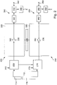
- the two channels 200, 300 and other components of the microwave generator 100 are in 2 explained in more detail in a circuit diagram. Typical signal paths are also marked with arrows.
- the microcontroller 112 is connected to the first port 114 and the second port 116 to communicate with other components of a microwave oven and to power and control the fan 150 .
- the microcontroller 112 is also connected to the first oscillator 210 and the second oscillator 310 .
- the first oscillator 210 is connected to a first voltage source 215 and the second oscillator 310 is connected to a second voltage source 315 .
- the two first and second voltage sources 215, 315 each supply a voltage of 3.3 V as input voltage for the oscillators 210, 310.
- the oscillators 210, 310 generate a respective output signal which has a specific frequency and is forwarded to the first amplifier circuit 220 and to the second amplifier circuit 320, respectively.
- the two oscillators 210, 310 are also electrically connected directly to one another, so that frequency or phase relationships with one another can be set via an exchange of information that is possible as a result.
- the oscillators can be operated with adjustable different frequencies and/or adjustable different phases. However, they can also be operated with identical frequency and/or identical phase.
- the first amplifier circuit 220 can be constructed using components such as transistors and/or operational amplifiers. In particular, it can be designed in two stages. In the present case, it is shown in simplified form as an operational amplifier 230 which is supplied by a third voltage source 240 . Correspondingly, the second amplifier circuit is shown in simplified form as an operational amplifier 330 which is supplied by a fourth voltage source 340 .
- the third and fourth voltage sources 240, 340 are fed by the voltage supply 130 and in the present case deliver a voltage of 28 V each.
- the first amplifier circuit 220 amplifies the signal supplied by the first oscillator 210 and forwards it to the first power measurement circuit 250. Accordingly, the second amplifier circuit 320 amplifies the signal supplied by the second oscillator 310 and forwards it to the second power measurement circuit 350.
- the first power measurement circuit 250 includes a first output power meter 252 , a first circulator 254 and a first reflection power meter 256 .
- the first circulator 254 is in turn connected to the first antenna 260 .
- the power delivered by the amplifier circuit 220 can be determined by means of the first output power meter 252 . This is routed via the first circulator 254 to the first antenna 260 and radiated from there. When waves reflected by the first antenna 260 are received, they are passed by the circulator 254 to the first reflection power meter 256 and then dissipated in a load resistor in the form of heat.
- This reflection power meter 256 measures the reflected power, so that a power actually remaining in the food to be cooked can be calculated from the difference between the emitted and reflected power.
- the power measurement for the advancing and returning waves can also be carried out in a combined power measurement unit downstream of the circulator 354 .
- the second power measurement circuit 350 includes a second output power meter 352 , a second circulator 354 and a second reflection power meter 356 .
- the second circulator 354 is connected to the second antenna 360 .
- the function of these components of the second channel 300 is identical to those of the first channel previously described.
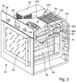
- the microwave oven 10 is designed as a combination device, which means that it can be operated both with microwaves and with conventional resistance heating.
- the microwave oven 10 has a cavity 20 which is accessible via a door 25 .
- the door 25 can be opened and closed. Items to be cooked which are to be heated by means of the microwave oven 10 can be introduced into the cavity 20 .
- the microwave oven 10 has a front panel 30 with a first rotary control 32, a second rotary control 34 and a display 36. Using the rotary controls 32, 34 and the display 36, a user can make settings in order to operate and use the microwave oven 10.
- the microwave generator 100 is arranged above the cavity 20 . Between the front panel 30 and The microwave generator 100 is arranged an air baffle 60, which is designed as a controllable air switch. It can guide the air flow 154 generated by the fan 150 of the microwave generator 100 either into the cavity 20 or through a gap between the door 25 and the front panel 30 . Thus, the airflow 154 can be directed into the cavity 20 when it is warmer than the interior of the cavity 20 to aid in heating. However, if the interior of the cavity 20 is already warmer than the air flow 154, the air flow can be directed to the outside in order not to cool the cavity 20 unnecessarily. Suitable temperature sensors (not shown) can be used to measure the temperature.
- a relay board 50 is arranged on the air baffle 60, on which various switches and control components for the microwave oven 10 are attached. In particular, relays are also arranged thereon, which control a resistance heating (not shown) of the microwave oven 10 .
- the relay board 50 is also cooled by the air flow 154 due to its arrangement on the air baffle 60, so that additional cooling components such as an otherwise conventional tangential fan can be dispensed with.
- the windscreen can also be cooled by the fan in a known manner if there is an air outlet between the front panel 30 and the door 25.
- the two antennas 260, 360 of the microwave generator 100 are accommodated in the respective waveguides 70, 75 of the cavity 20. This enables the microwaves emitted by the antennas 260, 360 to be coupled into the cavity 20, as is also the case in 3 based on the two paths 270, 370 is shown, which is already in the 1 are shown.
- Shielding devices are therefore preferably attached at the connection points of the waveguide to the cavity, which allow microwaves to pass through, but prevent the exchange of air. For example, plastics, glasses, ceramics or mica are suitable for this. These shielding devices also prevent dirt from entering the waveguide 70, 75, since it would be difficult to access them for cleaning.
- microwave generator 100 there is a conventional power pack 40 which supplies the entire microwave oven 10 or only the microwave generator 100 with electrical energy.
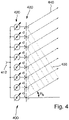
- FIG. 1 schematically shows a phased array antenna 400, such as can be used in a microwave oven, for example.
- this phased array antenna 400 can be used in the microwave oven 3 be used.
- the phased array antenna 400 has a signal input 410 to which a channel of a microwave generator can be connected.
- the signal input 410 is connected to a total of eight phase shifters 420 , each of which in turn is connected to an antenna 430 .
- the total of eight antennas 430 are arranged along a row with a respective spacing denoted by d. This distance d is identical for two adjacent antennas 430.
- An individual phase shift can be set for each of the antennas 430 by means of the phase shifter 420 .
- a distribution of the phases can be achieved in this way, with the phase shift between two adjacent antennas in each case increasing by a constant amount in one direction.
- the frequency of the emitted microwaves is identical.
- a propagation direction of emitted waves 440 can be set in a known manner with such a phase shift.
- the waves 440 are at an angle of ⁇ s to a direction transverse to the array of antennas 430 .
- This angle ⁇ S can be changed by different phase shifts between two adjacent antennas.
- Wavefronts 450, whose angle to the row of antennas 430 is identical to the angle ⁇ S run transversely to the waves 440 in each case.
- control of the direction of propagation of the waves 440 by means of a phase shift can be used in particular to specifically illuminate specific areas within a cavity.
- a function can thus be implemented, for example, in which an item to be cooked or also parts of an item to be cooked are recognized, for example by means of a camera or by evaluating the microwave reflection behavior with specifically selected settings. Based on this, heating can be targeted or stronger or weaker.
- any combination of a specific phase shifter with associated antenna can in this case be referred to as a channel, with all channels here being operated at the same frequency and only the phases differing.
- Such functions can also be used when operating the channels with different frequencies.
Landscapes
- Physics & Mathematics (AREA)
- Electromagnetism (AREA)
- Control Of High-Frequency Heating Circuits (AREA)
- Constitution Of High-Frequency Heating (AREA)
Claims (13)
- Générateur de micro-ondes (100) destiné à un four à micro-ondes (10), dans lequel- le générateur de micro-ondes (100) comporte au moins un premier canal (200) et un second canal (300),- le premier canal (200) comporte un premier circuit amplificateur (220) et une première antenne (260) connectée à celui-ci pour générer des micro-ondes ayant une puissance atteignant au maximum une première puissance partielle,- le second canal (300) comprend un second circuit amplificateur (320) et une seconde antenne (360) connectée à celui-ci pour générer des micro-ondes ayant une puissance atteignant au maximum une seconde puissance partielle,- une puissance totale maximale du générateur de micro-ondes (100) se compose des puissances partielles de ses canaux (200, 300),- chaque canal comporte un circuit de mesure de puissance respectif destiné à mesurer une puissance délivrée par le canal pour établir une boucle de régulation,- les circuits amplificateurs (220, 320) sont disposés sur une carte amplificatrice commune (120),caractérisé en ce que- une carte de commande (110), les antennes (260, 360) et un ventilateur (150) sont montés sur un dissipateur thermique (140) du générateur de micro-ondes (100),- les antennes (260, 360) sont directement reliées par câbles aux circuits amplificateurs (220, 320) respectifs sans interposition de connecteurs coaxiaux et de câbles coaxiaux.
- Générateur de micro-ondes (100) selon la revendication 1, caractérisé par un certain nombre d'autres canaux, dans lequel chaque autre canal comprend un circuit amplificateur respectif et une antenne respective connectée à celui-ci pour générer des micro-ondes ayant une puissance atteignant au maximum une puissance partielle respective.
- Générateur de micro-ondes (100) selon la revendication 1 ou 2, caractérisé en ce que les circuits amplificateurs (220, 320) comportent chacun un certain nombre de transistors (230, 330), en particulier des transistors de puissance, destinés à générer ou amplifier un courant attaquant l'antenne (260, 360) respective.
- Générateur de micro-ondes (100) selon l'une des revendications précédentes, caractérisé en ce que la carte amplificatrice (120) est directement montée sur le dissipateur thermique (140) du générateur de micro-ondes (100), de préférence sur une face inférieure plane du dissipateur thermique (140).
- Générateur de micro-ondes (100) selon l'une des revendications précédentes, caractérisé en ce que le ventilateur (150) est alimenté électriquement par une carte de commande (110) reliée à la carte amplificatrice (120) .
- Générateur de micro-ondes (100) selon l'une des revendications précédentes, caractérisé en ce que des cartes de circuits imprimés (110, 120) et/ou des antennes (260, 360) sont directement vissées sur le dissipateur thermique (140), dans lequel, en particulier, des ventilateurs (150) sont fixés au dissipateur thermique (140) par l'intermédiaire d'un support (152) respectif.
- Générateur de micro-ondes (100) selon l'une des revendications précédentes, caractérisé en ce que les antennes (260, 360) sont directement montées à une extrémité du dissipateur thermique (140), de préférence directement ou sans plaque à bride.
- Générateur de micro-ondes (100) selon l'une des revendications précédentes, caractérisé en ce qu'il est conçu pour attaquer les canaux (200, 300) avec différentes fréquences et/ou différentes phases, dans lequel, en particulier, les antennes (260, 360) forment ensemble une antenne à réseau phasé (400) et dans lequel le générateur de micro-ondes (100) est de préférence conçu pour régler une direction de propagation des micro-ondes rayonnées par l'antenne à réseau phasé (400) par le biais de relations de phase entre les canaux (200, 300).
- Générateur de micro-ondes (100) selon l'une des revendications précédentes, caractérisé en ce qu'il comporte un capot (160), en particulier constitué d'aluminium coulé sous pression, qui ferme au moins d'un côté, de préférence vers le bas, le générateur de micro-ondes (100) en le rendant étanche au micro-ondes, dans lequel le couvercle (160) forme, en particulier, un boîtier (140, 160) du générateur de micro-ondes (100) en association avec un dissipateur thermique (140).
- Four à micro-ondes (10), caractérisé par :- une cavité (20), et- un générateur de micro-ondes (100) selon l'une des revendications précédentes,dans lequel le générateur de micro-ondes (100) est conçu et est disposé dans le four à micro-ondes de manière à rayonner des micro-ondes dans la cavité (20).
- Four à micro-ondes (10) selon la revendication 10, caractérisé en ce qu'il comporte une plaque déflectrice d'air (60) destinée à guider de l'air chauffé depuis un dissipateur thermique (140) du générateur de micro-ondes (100) vers la cavité (20).
- Four à micro-ondes (10) selon la revendication 11, caractérisé en ce que la plaque déflectrice d'air (60) est réalisée sous la forme d'un déflecteur d'air pouvant être actionné de manière à ce qu'il puisse être amené à basculer entre une première position à laquelle il dirige l'air vers la cavité (20) et une seconde position à laquelle il dirige l'air vers l'environnement.
- Four à micro-ondes (10) selon l'une des revendications 10 à 12, caractérisé en ce qu'un ventilateur (150) du générateur de micro-ondes (100) est conçu pour refroidir également des composants supplémentaires (50) du four à micro-ondes (10), en particulier des composants d'un dispositif à résistance chauffante ou d'un dispositif de commande du four à micro-ondes (10).
Priority Applications (1)
| Application Number | Priority Date | Filing Date | Title |
|---|---|---|---|
| PL15198454.9T PL3035773T5 (pl) | 2014-12-17 | 2015-12-08 | Generator mikrofal i piec mikrofalowy |
Applications Claiming Priority (1)
| Application Number | Priority Date | Filing Date | Title |
|---|---|---|---|
| DE102014226280.1A DE102014226280B4 (de) | 2014-12-17 | 2014-12-17 | Mikrowellengenerator und Mikrowellenofen |
Publications (3)
| Publication Number | Publication Date |
|---|---|
| EP3035773A1 EP3035773A1 (fr) | 2016-06-22 |
| EP3035773B1 EP3035773B1 (fr) | 2019-08-21 |
| EP3035773B2 true EP3035773B2 (fr) | 2022-11-30 |
Family
ID=54843713
Family Applications (1)
| Application Number | Title | Priority Date | Filing Date |
|---|---|---|---|
| EP15198454.9A Active EP3035773B2 (fr) | 2014-12-17 | 2015-12-08 | Generateur de micro-ondes et four a micro-ondes |
Country Status (5)
| Country | Link |
|---|---|
| US (1) | US20160183332A1 (fr) |
| EP (1) | EP3035773B2 (fr) |
| DE (1) | DE102014226280B4 (fr) |
| ES (1) | ES2755155T5 (fr) |
| PL (1) | PL3035773T5 (fr) |
Families Citing this family (12)
| Publication number | Priority date | Publication date | Assignee | Title |
|---|---|---|---|---|
| DE102016210388A1 (de) | 2016-06-13 | 2017-12-14 | E.G.O. Elektro-Gerätebau GmbH | Mikrowellengenerator für ein Mikrowellengerät und Mikrowellengerät |
| DE102016216411A1 (de) * | 2016-08-31 | 2018-03-01 | E.G.O. Elektro-Gerätebau GmbH | Mikrowellenofen |
| US11122653B2 (en) * | 2016-09-30 | 2021-09-14 | Whirlpool Corporation | Intermediate transition between an antenna and a coplanar waveguide transmission line of a solid state amplifier |
| DE102016119286B4 (de) * | 2016-10-11 | 2020-06-10 | Miele & Cie. Kg | Gargerät |
| US10904959B2 (en) * | 2016-11-30 | 2021-01-26 | Illinois Tool Works, Inc. | Apparatus and system for solid state oven electronics cooling |
| US10764971B2 (en) | 2016-11-30 | 2020-09-01 | Illinois Tool Works, Inc. | Waveguide assembly for an RF oven |
| CN109416183B (zh) | 2016-12-27 | 2020-08-04 | 惠而浦公司 | 固态烹饪用微波炉中的纳米冷却 |
| JP6975777B2 (ja) | 2016-12-30 | 2021-12-01 | パナソニック株式会社 | 電磁調理器用の高電力増幅器のためのコスト効果の優れたハイブリッド保護 |
| DE102017111319A1 (de) | 2017-05-24 | 2018-11-29 | Miele & Cie. Kg | Einrichtung zur Erzeugung und Transmission von Hochfrequenzwellen (HF-Wellen) |
| DE102020110144A1 (de) | 2020-04-14 | 2021-10-14 | Miele & Cie. Kg | Hochfrequenzwellenheizmodul |
| CN111501264B (zh) * | 2020-04-28 | 2023-01-06 | 中山市普洛斯智能设备科技有限公司 | 用于织带固色机的微波加热装置 |
| EP4033862B1 (fr) | 2021-01-20 | 2023-12-27 | Electrolux Appliances Aktiebolag | Dispositif de chauffage, dispositif de rayonnement, procédé de fabrication d'un dispositif de chauffage et utilisation d'un dispositif d'affichage |
Family Cites Families (31)
| Publication number | Priority date | Publication date | Assignee | Title |
|---|---|---|---|---|
| US4131779A (en) * | 1976-07-07 | 1978-12-26 | Hitachi Heating Appliances Co., Ltd. | High-frequency heating apparatus |
| DE3104677A1 (de) * | 1981-02-10 | 1982-08-12 | Bosch Siemens Hausgeraete | Backofen, vorzugsweise mit einer thermischen heizeinrichtung sowie mit einer mikrowellen-heizeinrichtung |
| US4425543A (en) * | 1981-07-17 | 1984-01-10 | The United States Of America As Represented By The Administrator Of The National Aeronautics And Space Administration | High stability buffered phase comparator |
| JPS5999693A (ja) | 1982-11-30 | 1984-06-08 | 株式会社東芝 | 高周波加熱装置 |
| US4688002A (en) * | 1986-03-28 | 1987-08-18 | Wingate Steven L | Audio power amplifier |
| US5352991A (en) * | 1993-08-12 | 1994-10-04 | Motorola, Inc. | Power amplifier assembly |
| US5558800A (en) * | 1995-06-19 | 1996-09-24 | Northrop Grumman | Microwave power radiator for microwave heating applications |
| US6414644B1 (en) * | 2001-09-18 | 2002-07-02 | The Boeing Company | Channeled surface fairing for use with a phased array antenna on an aircraft |
| GB0509647D0 (en) * | 2005-05-12 | 2005-06-15 | Quintel Technology Ltd | Electrically steerable phased array antenna system |
| US10674570B2 (en) * | 2006-02-21 | 2020-06-02 | Goji Limited | System and method for applying electromagnetic energy |
| JP2008027493A (ja) * | 2006-07-19 | 2008-02-07 | Toshiba Corp | 半導体記憶装置 |
| JP5064924B2 (ja) | 2006-08-08 | 2012-10-31 | パナソニック株式会社 | マイクロ波処理装置 |
| JP5262250B2 (ja) * | 2008-04-01 | 2013-08-14 | パナソニック株式会社 | マイクロ波処理装置 |
| KR20110025174A (ko) * | 2008-06-25 | 2011-03-09 | 파나소닉 주식회사 | 마이크로파 가열 장치 |
| KR20110057134A (ko) | 2008-09-17 | 2011-05-31 | 파나소닉 주식회사 | 마이크로파 가열 장치 |
| US8327684B2 (en) * | 2008-10-21 | 2012-12-11 | Teledyne Scientific & Imaging, Llc | Method for adjusting resonance frequencies of a vibrating microelectromechanical device |
| EP2368408B1 (fr) * | 2008-11-26 | 2019-03-20 | Wireless Environment, LLC | Dispositifs d'éclairage sans fil et applications associées |
| RU2011151722A (ru) | 2009-05-19 | 2013-06-27 | Панасоник Корпорэйшн | Устройство микроволнового нагрева и способ микроволнового нагрева |
| JP5657016B2 (ja) * | 2009-11-10 | 2015-01-21 | ゴジ リミテッド | エネルギーを制御するための装置および方法 |
| WO2011138675A2 (fr) | 2010-05-03 | 2011-11-10 | Goji Ltd. | Analyse modale |
| EP2627585A4 (fr) * | 2010-10-12 | 2014-12-31 | Goji Ltd | Dispositif et procédé d'application d'énergie électromagnétique à un contenant |
| US9699835B2 (en) * | 2010-11-17 | 2017-07-04 | Goji Limited | Machine readable element and optical indicium for authenticating an item before processing |
| US20120164022A1 (en) * | 2010-12-22 | 2012-06-28 | Goji Limited | Methods and devices for processing objects by applying electromagnetic (em) energy |
| EP2674013B1 (fr) * | 2011-02-11 | 2017-05-10 | Goji Limited | Interface de commande d'un appareil d'application d'énergie |
| CN102374557B (zh) | 2011-10-31 | 2016-08-03 | 广东美的厨房电器制造有限公司 | 半导体微波炉的微波馈入结构 |
| WO2013103761A1 (fr) * | 2012-01-06 | 2013-07-11 | Ranjit Gharpurey | Four à micro-ondes avec réseau d'antennes |
| US9804104B2 (en) * | 2012-03-19 | 2017-10-31 | Goji Limited | Applying RF energy according to time variations in EM feedback |
| US10470255B2 (en) * | 2012-07-02 | 2019-11-05 | Goji Limited | RF energy application based on electromagnetic feedback |
| CN102769952B (zh) * | 2012-07-18 | 2015-03-11 | 广东格兰仕微波炉电器制造有限公司 | 半导体微波炉及其半导体微波发生器连接结构 |
| GB2512819B (en) * | 2013-03-18 | 2021-07-14 | Wayv Tech Limited | Microwave heating apparatus |
| EP2953425B1 (fr) | 2014-06-03 | 2019-08-21 | Ampleon Netherlands B.V. | Appareil de chauffage à fréquence radio |
-
2014
- 2014-12-17 DE DE102014226280.1A patent/DE102014226280B4/de active Active
-
2015
- 2015-12-08 ES ES15198454T patent/ES2755155T5/es active Active
- 2015-12-08 PL PL15198454.9T patent/PL3035773T5/pl unknown
- 2015-12-08 EP EP15198454.9A patent/EP3035773B2/fr active Active
- 2015-12-16 US US14/971,526 patent/US20160183332A1/en not_active Abandoned
Also Published As
| Publication number | Publication date |
|---|---|
| DE102014226280A1 (de) | 2016-06-23 |
| EP3035773A1 (fr) | 2016-06-22 |
| PL3035773T3 (pl) | 2020-02-28 |
| DE102014226280B4 (de) | 2019-06-13 |
| US20160183332A1 (en) | 2016-06-23 |
| EP3035773B1 (fr) | 2019-08-21 |
| ES2755155T3 (es) | 2020-04-21 |
| ES2755155T5 (es) | 2023-04-17 |
| PL3035773T5 (pl) | 2023-03-20 |
Similar Documents
| Publication | Publication Date | Title |
|---|---|---|
| EP3035773B1 (fr) | Générateur de micro-ondes et four à micro-ondes | |
| EP3407680A1 (fr) | Dispositif de production et de transmission des ondes haute fréquence (ondes rf) | |
| DE3928572C2 (fr) | ||
| DE69621549T2 (de) | Konvektions- und Mikrowellenofen | |
| DE102005005527A1 (de) | Induktionsheizeinrichtung und Kochfeldmulde mit einer solchen Induktionsheizeinrichtung | |
| EP3376827A1 (fr) | Système de préparation d'au moins une denrée alimentaire | |
| DE112015003208T5 (de) | Mikrowellen-Heizvorrichtung | |
| EP3258741B1 (fr) | Générateur de micro-ondes pour un appareil à micro-ondes et appareil à micro-ondes | |
| DE2921995C2 (de) | Mikrowellenheizeinrichtung | |
| JP2003173867A (ja) | 電子レンジ | |
| DE69927560T2 (de) | Kühlvorrichtung für Mikrowellenherde mit Halogenlampe | |
| DE69934279T2 (de) | Mikrowellenofen versehen mit Halogenlampen | |
| DE3216544A1 (de) | Hochfrequenzheizgeraet | |
| DE3047112C2 (de) | Elektrischer Ofen mit einer Mikrowellenheizeinrichtung und weiteren elektrischen Heizeinrichtungen | |
| EP2621246B1 (fr) | Agencement et procédé de réchauffement d'un milieu à l'aide d'un rayonnement à micro-ondes | |
| EP3897074A1 (fr) | Module de chauffage à ondes à haute fréquence | |
| EP1670290A1 (fr) | Appareil de cuisson muni d'un dispositf générateur de micro-ondes | |
| DE102016119286B4 (de) | Gargerät | |
| EP3623705A1 (fr) | Appareil de cuisson | |
| EP1643808B1 (fr) | Four destiné au traitement culinaire des aliments | |
| DE1565845B2 (de) | Mikrowellenherd | |
| DE1615463C3 (de) | Ofen mit Abstrahlung von Mikrowellenenergie und mit einem widerstandsbeheizten Metallelement | |
| EP2187703B1 (fr) | Appareil de cuisson doté d'une alimentation à micro-ondes | |
| EP0284958B1 (fr) | Dispositif de couplage d'un champ à micro-ondes à un four à micro-ondes | |
| BE1030947B1 (de) | Hochfrequenz-Haushaltsgerät, vorzugsweise Hochfrequenz-Gargerät |
Legal Events
| Date | Code | Title | Description |
|---|---|---|---|
| PUAI | Public reference made under article 153(3) epc to a published international application that has entered the european phase |
Free format text: ORIGINAL CODE: 0009012 |
|
| AK | Designated contracting states |
Kind code of ref document: A1 Designated state(s): AL AT BE BG CH CY CZ DE DK EE ES FI FR GB GR HR HU IE IS IT LI LT LU LV MC MK MT NL NO PL PT RO RS SE SI SK SM TR |
|
| AX | Request for extension of the european patent |
Extension state: BA ME |
|
| STAA | Information on the status of an ep patent application or granted ep patent |
Free format text: STATUS: REQUEST FOR EXAMINATION WAS MADE |
|
| 17P | Request for examination filed |
Effective date: 20161214 |
|
| RBV | Designated contracting states (corrected) |
Designated state(s): AL AT BE BG CH CY CZ DE DK EE ES FI FR GB GR HR HU IE IS IT LI LT LU LV MC MK MT NL NO PL PT RO RS SE SI SK SM TR |
|
| GRAP | Despatch of communication of intention to grant a patent |
Free format text: ORIGINAL CODE: EPIDOSNIGR1 |
|
| STAA | Information on the status of an ep patent application or granted ep patent |
Free format text: STATUS: GRANT OF PATENT IS INTENDED |
|
| INTG | Intention to grant announced |
Effective date: 20190411 |
|
| GRAS | Grant fee paid |
Free format text: ORIGINAL CODE: EPIDOSNIGR3 |
|
| GRAA | (expected) grant |
Free format text: ORIGINAL CODE: 0009210 |
|
| STAA | Information on the status of an ep patent application or granted ep patent |
Free format text: STATUS: THE PATENT HAS BEEN GRANTED |
|
| AK | Designated contracting states |
Kind code of ref document: B1 Designated state(s): AL AT BE BG CH CY CZ DE DK EE ES FI FR GB GR HR HU IE IS IT LI LT LU LV MC MK MT NL NO PL PT RO RS SE SI SK SM TR |
|
| REG | Reference to a national code |
Ref country code: GB Ref legal event code: FG4D Free format text: NOT ENGLISH |
|
| REG | Reference to a national code |
Ref country code: CH Ref legal event code: EP |
|
| REG | Reference to a national code |
Ref country code: DE Ref legal event code: R096 Ref document number: 502015010049 Country of ref document: DE |
|
| REG | Reference to a national code |
Ref country code: AT Ref legal event code: REF Ref document number: 1171224 Country of ref document: AT Kind code of ref document: T Effective date: 20190915 |
|
| REG | Reference to a national code |
Ref country code: IE Ref legal event code: FG4D Free format text: LANGUAGE OF EP DOCUMENT: GERMAN |
|
| REG | Reference to a national code |
Ref country code: LT Ref legal event code: MG4D |
|
| REG | Reference to a national code |
Ref country code: NL Ref legal event code: MP Effective date: 20190821 |
|
| PG25 | Lapsed in a contracting state [announced via postgrant information from national office to epo] |
Ref country code: FI Free format text: LAPSE BECAUSE OF FAILURE TO SUBMIT A TRANSLATION OF THE DESCRIPTION OR TO PAY THE FEE WITHIN THE PRESCRIBED TIME-LIMIT Effective date: 20190821 Ref country code: HR Free format text: LAPSE BECAUSE OF FAILURE TO SUBMIT A TRANSLATION OF THE DESCRIPTION OR TO PAY THE FEE WITHIN THE PRESCRIBED TIME-LIMIT Effective date: 20190821 Ref country code: SE Free format text: LAPSE BECAUSE OF FAILURE TO SUBMIT A TRANSLATION OF THE DESCRIPTION OR TO PAY THE FEE WITHIN THE PRESCRIBED TIME-LIMIT Effective date: 20190821 Ref country code: NO Free format text: LAPSE BECAUSE OF FAILURE TO SUBMIT A TRANSLATION OF THE DESCRIPTION OR TO PAY THE FEE WITHIN THE PRESCRIBED TIME-LIMIT Effective date: 20191121 Ref country code: PT Free format text: LAPSE BECAUSE OF FAILURE TO SUBMIT A TRANSLATION OF THE DESCRIPTION OR TO PAY THE FEE WITHIN THE PRESCRIBED TIME-LIMIT Effective date: 20191223 Ref country code: LT Free format text: LAPSE BECAUSE OF FAILURE TO SUBMIT A TRANSLATION OF THE DESCRIPTION OR TO PAY THE FEE WITHIN THE PRESCRIBED TIME-LIMIT Effective date: 20190821 Ref country code: NL Free format text: LAPSE BECAUSE OF FAILURE TO SUBMIT A TRANSLATION OF THE DESCRIPTION OR TO PAY THE FEE WITHIN THE PRESCRIBED TIME-LIMIT Effective date: 20190821 Ref country code: BG Free format text: LAPSE BECAUSE OF FAILURE TO SUBMIT A TRANSLATION OF THE DESCRIPTION OR TO PAY THE FEE WITHIN THE PRESCRIBED TIME-LIMIT Effective date: 20191121 |
|
| PG25 | Lapsed in a contracting state [announced via postgrant information from national office to epo] |
Ref country code: GR Free format text: LAPSE BECAUSE OF FAILURE TO SUBMIT A TRANSLATION OF THE DESCRIPTION OR TO PAY THE FEE WITHIN THE PRESCRIBED TIME-LIMIT Effective date: 20191122 Ref country code: LV Free format text: LAPSE BECAUSE OF FAILURE TO SUBMIT A TRANSLATION OF THE DESCRIPTION OR TO PAY THE FEE WITHIN THE PRESCRIBED TIME-LIMIT Effective date: 20190821 Ref country code: AL Free format text: LAPSE BECAUSE OF FAILURE TO SUBMIT A TRANSLATION OF THE DESCRIPTION OR TO PAY THE FEE WITHIN THE PRESCRIBED TIME-LIMIT Effective date: 20190821 Ref country code: RS Free format text: LAPSE BECAUSE OF FAILURE TO SUBMIT A TRANSLATION OF THE DESCRIPTION OR TO PAY THE FEE WITHIN THE PRESCRIBED TIME-LIMIT Effective date: 20190821 Ref country code: IS Free format text: LAPSE BECAUSE OF FAILURE TO SUBMIT A TRANSLATION OF THE DESCRIPTION OR TO PAY THE FEE WITHIN THE PRESCRIBED TIME-LIMIT Effective date: 20191221 |
|
| REG | Reference to a national code |
Ref country code: ES Ref legal event code: FG2A Ref document number: 2755155 Country of ref document: ES Kind code of ref document: T3 Effective date: 20200421 |
|
| PG25 | Lapsed in a contracting state [announced via postgrant information from national office to epo] |
Ref country code: EE Free format text: LAPSE BECAUSE OF FAILURE TO SUBMIT A TRANSLATION OF THE DESCRIPTION OR TO PAY THE FEE WITHIN THE PRESCRIBED TIME-LIMIT Effective date: 20190821 Ref country code: RO Free format text: LAPSE BECAUSE OF FAILURE TO SUBMIT A TRANSLATION OF THE DESCRIPTION OR TO PAY THE FEE WITHIN THE PRESCRIBED TIME-LIMIT Effective date: 20190821 Ref country code: DK Free format text: LAPSE BECAUSE OF FAILURE TO SUBMIT A TRANSLATION OF THE DESCRIPTION OR TO PAY THE FEE WITHIN THE PRESCRIBED TIME-LIMIT Effective date: 20190821 |
|
| REG | Reference to a national code |
Ref country code: DE Ref legal event code: R026 Ref document number: 502015010049 Country of ref document: DE |
|
| PLBI | Opposition filed |
Free format text: ORIGINAL CODE: 0009260 |
|
| PG25 | Lapsed in a contracting state [announced via postgrant information from national office to epo] |
Ref country code: SK Free format text: LAPSE BECAUSE OF FAILURE TO SUBMIT A TRANSLATION OF THE DESCRIPTION OR TO PAY THE FEE WITHIN THE PRESCRIBED TIME-LIMIT Effective date: 20190821 Ref country code: CZ Free format text: LAPSE BECAUSE OF FAILURE TO SUBMIT A TRANSLATION OF THE DESCRIPTION OR TO PAY THE FEE WITHIN THE PRESCRIBED TIME-LIMIT Effective date: 20190821 Ref country code: SM Free format text: LAPSE BECAUSE OF FAILURE TO SUBMIT A TRANSLATION OF THE DESCRIPTION OR TO PAY THE FEE WITHIN THE PRESCRIBED TIME-LIMIT Effective date: 20190821 Ref country code: IS Free format text: LAPSE BECAUSE OF FAILURE TO SUBMIT A TRANSLATION OF THE DESCRIPTION OR TO PAY THE FEE WITHIN THE PRESCRIBED TIME-LIMIT Effective date: 20200224 |
|
| PLAX | Notice of opposition and request to file observation + time limit sent |
Free format text: ORIGINAL CODE: EPIDOSNOBS2 |
|
| 26 | Opposition filed |
Opponent name: ELECTROLUX ROTHENBURG GMBH FACTORY AND DEVELOPMENT Effective date: 20200519 |
|
| PG2D | Information on lapse in contracting state deleted |
Ref country code: IS |
|
| REG | Reference to a national code |
Ref country code: CH Ref legal event code: PL |
|
| REG | Reference to a national code |
Ref country code: BE Ref legal event code: MM Effective date: 20191231 |
|
| PG25 | Lapsed in a contracting state [announced via postgrant information from national office to epo] |
Ref country code: MC Free format text: LAPSE BECAUSE OF FAILURE TO SUBMIT A TRANSLATION OF THE DESCRIPTION OR TO PAY THE FEE WITHIN THE PRESCRIBED TIME-LIMIT Effective date: 20190821 Ref country code: SI Free format text: LAPSE BECAUSE OF FAILURE TO SUBMIT A TRANSLATION OF THE DESCRIPTION OR TO PAY THE FEE WITHIN THE PRESCRIBED TIME-LIMIT Effective date: 20190821 |
|
| GBPC | Gb: european patent ceased through non-payment of renewal fee |
Effective date: 20191208 |
|
| PLBB | Reply of patent proprietor to notice(s) of opposition received |
Free format text: ORIGINAL CODE: EPIDOSNOBS3 |
|
| PG25 | Lapsed in a contracting state [announced via postgrant information from national office to epo] |
Ref country code: LU Free format text: LAPSE BECAUSE OF NON-PAYMENT OF DUE FEES Effective date: 20191208 Ref country code: GB Free format text: LAPSE BECAUSE OF NON-PAYMENT OF DUE FEES Effective date: 20191208 Ref country code: IE Free format text: LAPSE BECAUSE OF NON-PAYMENT OF DUE FEES Effective date: 20191208 |
|
| PG25 | Lapsed in a contracting state [announced via postgrant information from national office to epo] |
Ref country code: BE Free format text: LAPSE BECAUSE OF NON-PAYMENT OF DUE FEES Effective date: 20191231 Ref country code: LI Free format text: LAPSE BECAUSE OF NON-PAYMENT OF DUE FEES Effective date: 20191231 Ref country code: CH Free format text: LAPSE BECAUSE OF NON-PAYMENT OF DUE FEES Effective date: 20191231 |
|
| PG25 | Lapsed in a contracting state [announced via postgrant information from national office to epo] |
Ref country code: CY Free format text: LAPSE BECAUSE OF FAILURE TO SUBMIT A TRANSLATION OF THE DESCRIPTION OR TO PAY THE FEE WITHIN THE PRESCRIBED TIME-LIMIT Effective date: 20190821 |
|
| PG25 | Lapsed in a contracting state [announced via postgrant information from national office to epo] |
Ref country code: MT Free format text: LAPSE BECAUSE OF FAILURE TO SUBMIT A TRANSLATION OF THE DESCRIPTION OR TO PAY THE FEE WITHIN THE PRESCRIBED TIME-LIMIT Effective date: 20190821 Ref country code: HU Free format text: LAPSE BECAUSE OF FAILURE TO SUBMIT A TRANSLATION OF THE DESCRIPTION OR TO PAY THE FEE WITHIN THE PRESCRIBED TIME-LIMIT; INVALID AB INITIO Effective date: 20151208 |
|
| REG | Reference to a national code |
Ref country code: AT Ref legal event code: MM01 Ref document number: 1171224 Country of ref document: AT Kind code of ref document: T Effective date: 20201208 |
|
| PG25 | Lapsed in a contracting state [announced via postgrant information from national office to epo] |
Ref country code: AT Free format text: LAPSE BECAUSE OF NON-PAYMENT OF DUE FEES Effective date: 20201208 |
|
| APBM | Appeal reference recorded |
Free format text: ORIGINAL CODE: EPIDOSNREFNO |
|
| APBP | Date of receipt of notice of appeal recorded |
Free format text: ORIGINAL CODE: EPIDOSNNOA2O |
|
| APAH | Appeal reference modified |
Free format text: ORIGINAL CODE: EPIDOSCREFNO |
|
| PG25 | Lapsed in a contracting state [announced via postgrant information from national office to epo] |
Ref country code: MK Free format text: LAPSE BECAUSE OF FAILURE TO SUBMIT A TRANSLATION OF THE DESCRIPTION OR TO PAY THE FEE WITHIN THE PRESCRIBED TIME-LIMIT Effective date: 20190821 |
|
| APBU | Appeal procedure closed |
Free format text: ORIGINAL CODE: EPIDOSNNOA9O |
|
| PUAH | Patent maintained in amended form |
Free format text: ORIGINAL CODE: 0009272 |
|
| STAA | Information on the status of an ep patent application or granted ep patent |
Free format text: STATUS: PATENT MAINTAINED AS AMENDED |
|
| 27A | Patent maintained in amended form |
Effective date: 20221130 |
|
| AK | Designated contracting states |
Kind code of ref document: B2 Designated state(s): AL AT BE BG CH CY CZ DE DK EE ES FI FR GB GR HR HU IE IS IT LI LT LU LV MC MK MT NL NO PL PT RO RS SE SI SK SM TR |
|
| REG | Reference to a national code |
Ref country code: DE Ref legal event code: R102 Ref document number: 502015010049 Country of ref document: DE |
|
| REG | Reference to a national code |
Ref country code: ES Ref legal event code: DC2A Ref document number: 2755155 Country of ref document: ES Kind code of ref document: T5 Effective date: 20230417 |
|
| PGFP | Annual fee paid to national office [announced via postgrant information from national office to epo] |
Ref country code: DE Payment date: 20251217 Year of fee payment: 11 |
|
| PGFP | Annual fee paid to national office [announced via postgrant information from national office to epo] |
Ref country code: FR Payment date: 20251218 Year of fee payment: 11 |
|
| PGFP | Annual fee paid to national office [announced via postgrant information from national office to epo] |
Ref country code: TR Payment date: 20251202 Year of fee payment: 11 |
|
| PGFP | Annual fee paid to national office [announced via postgrant information from national office to epo] |
Ref country code: PL Payment date: 20251103 Year of fee payment: 11 |
|
| PGFP | Annual fee paid to national office [announced via postgrant information from national office to epo] |
Ref country code: ES Payment date: 20260119 Year of fee payment: 11 |
|
| PGFP | Annual fee paid to national office [announced via postgrant information from national office to epo] |
Ref country code: IT Payment date: 20251231 Year of fee payment: 11 |