EP3036203B1 - Procédé permettant d'arrondir les bords acérés d'objets en verre - Google Patents
Procédé permettant d'arrondir les bords acérés d'objets en verre Download PDFInfo
- Publication number
- EP3036203B1 EP3036203B1 EP14838714.5A EP14838714A EP3036203B1 EP 3036203 B1 EP3036203 B1 EP 3036203B1 EP 14838714 A EP14838714 A EP 14838714A EP 3036203 B1 EP3036203 B1 EP 3036203B1
- Authority
- EP
- European Patent Office
- Prior art keywords
- glass
- laser beam
- edge
- ring
- treating
- Prior art date
- Legal status (The legal status is an assumption and is not a legal conclusion. Google has not performed a legal analysis and makes no representation as to the accuracy of the status listed.)
- Active
Links
Images

Classifications
-
- C—CHEMISTRY; METALLURGY
- C03—GLASS; MINERAL OR SLAG WOOL
- C03C—CHEMICAL COMPOSITION OF GLASSES, GLAZES OR VITREOUS ENAMELS; SURFACE TREATMENT OF GLASS; SURFACE TREATMENT OF FIBRES OR FILAMENTS MADE FROM GLASS, MINERALS OR SLAGS; JOINING GLASS TO GLASS OR OTHER MATERIALS
- C03C23/00—Other surface treatment of glass not in the form of fibres or filaments
- C03C23/0005—Other surface treatment of glass not in the form of fibres or filaments by irradiation
- C03C23/0025—Other surface treatment of glass not in the form of fibres or filaments by irradiation by a laser beam
-
- B—PERFORMING OPERATIONS; TRANSPORTING
- B23—MACHINE TOOLS; METAL-WORKING NOT OTHERWISE PROVIDED FOR
- B23K—SOLDERING OR UNSOLDERING; WELDING; CLADDING OR PLATING BY SOLDERING OR WELDING; CUTTING BY APPLYING HEAT LOCALLY, e.g. FLAME CUTTING; WORKING BY LASER BEAM
- B23K26/00—Working by laser beam, e.g. welding, cutting or boring
- B23K26/0006—Working by laser beam, e.g. welding, cutting or boring taking account of the properties of the material involved
-
- B—PERFORMING OPERATIONS; TRANSPORTING
- B23—MACHINE TOOLS; METAL-WORKING NOT OTHERWISE PROVIDED FOR
- B23K—SOLDERING OR UNSOLDERING; WELDING; CLADDING OR PLATING BY SOLDERING OR WELDING; CUTTING BY APPLYING HEAT LOCALLY, e.g. FLAME CUTTING; WORKING BY LASER BEAM
- B23K26/00—Working by laser beam, e.g. welding, cutting or boring
- B23K26/02—Positioning or observing the workpiece, e.g. with respect to the point of impact; Aligning, aiming or focusing the laser beam
- B23K26/06—Shaping the laser beam, e.g. by masks or multi-focusing
- B23K26/073—Shaping the laser spot
- B23K26/0734—Shaping the laser spot into an annular shape
-
- B—PERFORMING OPERATIONS; TRANSPORTING
- B23—MACHINE TOOLS; METAL-WORKING NOT OTHERWISE PROVIDED FOR
- B23K—SOLDERING OR UNSOLDERING; WELDING; CLADDING OR PLATING BY SOLDERING OR WELDING; CUTTING BY APPLYING HEAT LOCALLY, e.g. FLAME CUTTING; WORKING BY LASER BEAM
- B23K26/00—Working by laser beam, e.g. welding, cutting or boring
- B23K26/352—Working by laser beam, e.g. welding, cutting or boring for surface treatment
-
- B—PERFORMING OPERATIONS; TRANSPORTING
- B23—MACHINE TOOLS; METAL-WORKING NOT OTHERWISE PROVIDED FOR
- B23K—SOLDERING OR UNSOLDERING; WELDING; CLADDING OR PLATING BY SOLDERING OR WELDING; CUTTING BY APPLYING HEAT LOCALLY, e.g. FLAME CUTTING; WORKING BY LASER BEAM
- B23K26/00—Working by laser beam, e.g. welding, cutting or boring
- B23K26/352—Working by laser beam, e.g. welding, cutting or boring for surface treatment
- B23K26/3568—Modifying rugosity
- B23K26/3576—Diminishing rugosity, e.g. by grinding, polishing or smoothing
-
- C—CHEMISTRY; METALLURGY
- C03—GLASS; MINERAL OR SLAG WOOL
- C03B—MANUFACTURE, SHAPING, OR SUPPLEMENTARY PROCESSES
- C03B29/00—Reheating glass products for softening or fusing their surfaces; Fire-polishing; Fusing of margins
-
- C—CHEMISTRY; METALLURGY
- C03—GLASS; MINERAL OR SLAG WOOL
- C03B—MANUFACTURE, SHAPING, OR SUPPLEMENTARY PROCESSES
- C03B29/00—Reheating glass products for softening or fusing their surfaces; Fire-polishing; Fusing of margins
- C03B29/02—Reheating glass products for softening or fusing their surfaces; Fire-polishing; Fusing of margins in a discontinuous way
- C03B29/025—Glass sheets
-
- C—CHEMISTRY; METALLURGY
- C03—GLASS; MINERAL OR SLAG WOOL
- C03B—MANUFACTURE, SHAPING, OR SUPPLEMENTARY PROCESSES
- C03B33/00—Severing cooled glass
- C03B33/08—Severing cooled glass by fusing, i.e. by melting through the glass
- C03B33/082—Severing cooled glass by fusing, i.e. by melting through the glass using a focussed radiation beam, e.g. laser
-
- B—PERFORMING OPERATIONS; TRANSPORTING
- B23—MACHINE TOOLS; METAL-WORKING NOT OTHERWISE PROVIDED FOR
- B23K—SOLDERING OR UNSOLDERING; WELDING; CLADDING OR PLATING BY SOLDERING OR WELDING; CUTTING BY APPLYING HEAT LOCALLY, e.g. FLAME CUTTING; WORKING BY LASER BEAM
- B23K2103/00—Materials to be soldered, welded or cut
- B23K2103/50—Inorganic materials other than metals or composite materials
- B23K2103/54—Glass
Definitions
- the invention relates to methods for processing glass objects, in particular, to methods for blunting sharp edges of glass objects.
- the present invention can be used in various industries involved in processing of glass for blunting edges.
- Laser is characterized by a monochromatic light having a large coherence length. Lasers are employed in many industrial and medical applications. Significant technical applications of lasers include, for example, spectroscopy, laser measurement of distance, and lasers are also used in processes of precision cutting and welding of metals, ceramics and glass.
- WO 03015976 A1 discloses a method of chamfering edges of a glass substrate, which comprises: treating a glass edge successively with a first focused laser beam with a low heat energy intensity, having an elliptical heat spot located at an angle relative to the glass edge, wherein when the glass substrate is moved in the feed direction, the first laser spot, after preheating the portion of the glass substrate in the vicinity of the edge, melts and chamfers the edge, and then the substrate is heated by a second laser beam having a heat spot in the shape of an ellipse elongated in the direction of movement of the glass substrate.
- the method is difficult to be put in practice, and "tempering" the glass, i. e. removing thermal stresses caused by melting the glass is impossible in such a short time.
- Document KR-B-100820689 discloses a method for blunting sharp edges of glass objects comprising treating the glass edges with a focused laser beam wherein a first laser spot as well as a second laser spot both have elliptic shape.
- a similar disclosure is known from US 6,407,306 B1 which teaches to use an elliptical focused beam not only for cutting glass objects but also for a simultaneously grinding of the edges of a cut face.
- the most relevant prior art is a method of blunting sharp edges of objects, taught in RU 2163226 C1 , which comprises heating at least one surface of the edge by a portion of a beam or by one of two separate beams to a temperature not exceeding the melting point of the material, and heating the other surface of the edge of the object by the other portion of the beam or by the second individual beam.
- the laser beam used for heating has an elliptical sectional shape on the surface of the material. Disadvantages of this method include the reduction in strength due to possible residual thermal stresses, and the likelihood of breaking off chips of the material being detached, as well as poor controllability of the process due to different distribution of the power density in each of the treatment spots, where the distribution uniformity can be only theoretical.
- the object of the present invention is to provide a method for blunting sharp edges of glass objects, which ensures better quality products, increases the speed of processing glass objects, while providing a chamfer with a minimal required size which is constant throughout the length of treatment and increasing the strength of the products.
- the object is accomplished in a method for blunting sharp edges of glass objects according to the invention, which comprises treating the glass edge with a focused laser beam having a ring-shaped section, while relatively moving the glass object and/or the beam, said treating comprising heating the glass edge with the laser beam to a temperature above glass transition temperature, T > Tg.
- the beam having a ring-shaped section here refers to a beam produced by a coaxial lens, which transforms a beam having a solid section into a beam having a ring-shaped section.
- An exemplary beam transformer is an assembly consisting of two mirror cones, external and internal (referred to as "axicon").
- Glass transition temperature Tg is one of the basic characteristics of polymeric materials. At a temperature below the glass transition temperature a polymeric material is in a more hard and brittle state; when this temperature is exceeded the material substantially intermittently transits to plastic state. With this, the thermal expansion coefficient of the material increases dramatically as well. The glass transition temperature is difficult to be exactly determined because of the spread characteristics of materials and the application of various techniques. For most industrial glass, Tg is within the range of 400-600°C.
- the ring-shaped section of the laser beam is a determining factor for chamfering glass objects, which prevents damage to the glass surface and chipping.
- it creates tempered glass areas of desired shape and size in the near-edge region due to thermal stresses in these areas, thereby providing the formation of a chamfer with rounded or blunt ends on the glass at brittle fracture.
- the method according to the invention allows the creation, in the near-edge region, of hardened glass sections with thermal stresses, the magnitude and direction of which provide the formation of chamfers with rounded ends on the glass at brittle fracture.
- the laser beam is preferably directed so that its axis lies at an angle of 20-70° to the plane, which is a continuation of the glass surface facing the laser beam. Beyond the lower limit the most of the beam (up to 70%) will be reflected, and conditions for chipping and chamfering will be infeasible, while above the upper limit a groove will be formed rather than a chamfer.
- said angle lies in the plane perpendicular to the vector of movement of the glass object and/or beam.
- the axis of the laser beam can also be directed at an angle of 0-30° to the plane perpendicular to the vector of said movement of the glass object and/or beam.
- the treatment is carried with a laser beam having the shape of a ring elongated in the direction of the movement of said glass object and/or the beam to produce a heat spot in the shape of an elongated ring.
- a laser beam having the shape of a ring elongated in the direction of the movement of said glass object and/or the beam to produce a heat spot in the shape of an elongated ring.
- the treatment with a laser beam preferably comprises removing the glass material in the form of chip to chamfer the glass edge, and the size of the chamfer is defined by the minor axis of the heat spot, radiation power density at the heat spot W (watts/sq cm), and exposure time ⁇ (s).
- a coolant may be supplied to the heating area.
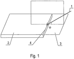
- a method of blunting sharp edges of glass objects comprises: treating an edge of glass object 1 with a focused laser beam 2 having a ring-shaped section, while relatively moving the glass object and/or the beam.
- the treatment with a laser beam comprises heating the glass edge 4 to a temperature above glass transition temperature, T > Tg. This causes removal of the glass material in the form of chip 3 from the edge 4 of the glass object 1 to form a chamfer.
- the laser beam 2 whose heat spot is preferably a ring-shaped ellipse, is directed at the glass 1 edge to be chamfered at an angle to a plane 3, which is a continuation of the glass 1 surface facing the laser beam 2.
- the laser beam is preferably moved along the glass 1 edge in a straight line at a constant speed and constant focal distance.
- the laser beam can be moved in the region of corners at a different speed and with a modified size of heat spot to maintain stable heating conditions.
- the ring-shaped ellipse of the heat spot (shown schematically in Fig.1 ) has the major axis of 11 mm and the minor axis of 3 mm.
- the angle at which the laser beam is directed at the glass edge is 45° in this embodiment.
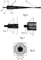
- a lens system is used, which is schematically shown in Fig.6 and consists, in particular, of two mirror cones: an internal cone 5 (referred to as "axicon") and a truncated external cone 6.
- Fig.7 shows that the diameter of the resulting ring-shaped beam changes as a function of the position of the axicon 6 relative to the external cone 5.
- the outer diameter of the section of the ring-shaped beam emitted from the cone 6 will be 8 mm. Accordingly, if the distance is 2 mm, the diameter is 12 mm, and with the distance of 4 mm the diameter is 16 mm.
- the system may also comprise a pair of cylindrical lens 8, one of which compresses the ring-shaped beam in one plane, and the other lens does the same in the other plane thereby changing the size of the axes of the ring-shaped ellipse.
- Fig.8 shows that mutual rotation of the cylindrical lenses 8 (changing angle ⁇ ) modifies the shape of the heat spot.
- the illustrated system further comprises: a source detector 9, an axicon detector 10, and a focus detector 11.
- a coaxial conical lens which transforms a beam having a solid section into a beam having a ring-shaped section
- a cylindrical lens which stretches the ring to an ellipse, provides simultaneously a ring-shaped and elongated laser beam in the direction of movement of the glass object and/or beam.
- glass transition temperature Tg for most commercial glasses ranges within 400-600°C.
- heating is preferably provided to a temperature of 650-680°C, followed by cooling with a liquid/air mixture.
- evaporation sublimation of the material
- the laser beam whose heat spot was a ring-shaped ellipse having the major axis of 11 mm and the minor axis of 3 mm, was directed onto the glass edge to be chamfered at an angle of 45° (or some other angle from 45+30° to 45-15°) and moved along a straight line at a constant speed and constant focal distance.
- the laser energy was absorbed in a thin surface layer, as the glass was opaque for the laser beam. Therefore, the laser energy passed further into the depth of the material by thermal conduction.
- the extent of heating the glass surface exposed to laser radiation depends on the following factors: power and power density w (watts/sq cm) of laser radiation, speed of relative movement of the laser beam and/or glass, exposure time ⁇ (s), and speed of heat dissipation from the surface into the depth of glass, which is defined by the thermal conductivity factor_of glass.
- the same characteristics also determine the chamfer size, which is also set by the size of the minor axis of the heat spot ellipse.
- the chamfer size can range from a few hundredths of a millimeter to several millimeters.
- the angle of inclination of the chamfer relative to the surface of the glass which depends on the angle at which the axis of the laser beam is directed to the treated glass surface, can be varied.
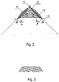
- Fig.2 shows schematically processes occurring in the edge in the course of treatment with a ring-shaped laser beam in accordance with the invention.
- heating gives rise to portions of expanded glass formed in areas 12 adjacent to the glass edge 4, between which a hardened glass portion 13 is formed.
- stresses are acting at the microcrack rounding site 14: bending moment M, thermal stress caused by bending, and thermal stress Gr caused by cooling. Glass material separates along the microcrack trajectory 15.
- Fig.3 illustrates in sectional view that the resulting chamfer has rounded edges owing to the present method.
- Fig.4 shows schematically thermal stresses arising in the glass treated with a laser beam at surface absorption. It is shown for simplicity that the laser beam 2 is directed vertically to the elementary fragment of the heated area of glass 1. The following thermal stresses arise in the glass:
- Comparative graphs shown in Fig.5 demonstrate that a ring is the best shape of the spot to provide thermal cleavage, with the shape of an ellipse being preferred.
- the laser beam is directed so that its axis lies at an angle of 20-70° to the plane, which is a continuation of the glass surface facing the laser beam.
- the angle is preferably disposed in the plane perpendicular to the vector of said movement of the glass object and/or beam.
- the axis of the laser beam can be directed at an angle of 0-30° to the plane perpendicular to the vector of movement of the glass and/or beam.
- the treatment is most preferably carried out with a laser beam having the shape of a ring elongated in the direction of movement of the glass object and/or beam to obtain a heat spot in the shape of an elongated ring, for example, an elongated ellipse, which enhances the efficiency of chamfering process.
- a laser beam having the shape of a ring elongated in the direction of movement of the glass object and/or beam to obtain a heat spot in the shape of an elongated ring, for example, an elongated ellipse, which enhances the efficiency of chamfering process.
- the possibility of rotating the elliptical beam with respect to the direction of movement should be provided.
- the chamfer size is specified by the size of the minor axis of the heat spot, the power density in the heat spot w (watts/sq cm), and exposure time ⁇ (s).
- a coolant is preferably fed in the heating area to locally cool the heating area.
Landscapes
- Engineering & Computer Science (AREA)
- Physics & Mathematics (AREA)
- Optics & Photonics (AREA)
- Chemical & Material Sciences (AREA)
- Plasma & Fusion (AREA)
- Materials Engineering (AREA)
- Organic Chemistry (AREA)
- Mechanical Engineering (AREA)
- Toxicology (AREA)
- Health & Medical Sciences (AREA)
- Life Sciences & Earth Sciences (AREA)
- Chemical Kinetics & Catalysis (AREA)
- General Chemical & Material Sciences (AREA)
- Geochemistry & Mineralogy (AREA)
- Re-Forming, After-Treatment, Cutting And Transporting Of Glass Products (AREA)
- Laser Beam Processing (AREA)
Claims (7)
- Procédé d'émoussement de bords tranchants d'objets en verre, comprenant le traitement du bord tranchant avec un faisceau laser focalisé, tout en déplaçant de manière relative l'objet en verre et/ou le faisceau, dans lequel ledit traitement comprend le chauffage du bord de verre avec le faisceau laser à une température supérieure à la température de transition vitreuse, T > Tg,
caractérisé en ce que
ledit traitement du bord en verre est réalisé avec le faisceau laser présentant une section annulaire. - Procédé selon la revendication 1, dans lequel ledit faisceau laser est dirigé vers le bord de verre de manière à ce que son axe soit disposé selon un angle de 20-70° par rapport au plan constituant une prolongation de la surface de verre tournée vers le faisceau laser.
- Procédé selon la revendication 2, dans lequel ledit angle se situe dans le plan perpendiculaire au vecteur de déplacement de l'objet en verre et/ou du faisceau.
- Procédé selon la revendication 2, dans lequel l'axe du faisceau laser est dirigé selon un angle de 0-30° par rapport au plan perpendiculaire au vecteur de déplacement de l'objet en verre et/ou du faisceau.
- Procédé selon la revendication 1, dans lequel ledit traitement est réalisé avec un faisceau laser présentant la forme d'un anneau allongé dans la direction de déplacement dudit objet en verre et/ou dudit faisceau pour produire un point de chaleur en forme d'anneau allongé.
- Procédé selon la revendication 1 ou 5, dans lequel ledit traitement au faisceau laser comprend le retrait du matériau en verre sous la forme de copeaux pour chanfreiner le bord de verre.
- Procédé selon la revendication 6, dans lequel la taille du chanfrein est définie par l'axe mineur du point de chaleur, la densité de la puissance de rayonnement au niveau du point de chaleur W (watts/cm2), et le temps d'exposition τ (s).
Priority Applications (1)
| Application Number | Priority Date | Filing Date | Title |
|---|---|---|---|
| PL14838714T PL3036203T3 (pl) | 2013-08-23 | 2014-08-05 | Sposób stępiania ostrych krawędzi szklanych przedmiotów |
Applications Claiming Priority (2)
| Application Number | Priority Date | Filing Date | Title |
|---|---|---|---|
| RU2013139383/03A RU2543222C1 (ru) | 2013-08-23 | 2013-08-23 | Способ притупления острых кромок стеклоизделий |
| PCT/RU2014/000586 WO2015026267A1 (fr) | 2013-08-23 | 2014-08-05 | Procédé permettant d'arrondir les bords acérés d'objets en verre |
Publications (3)
| Publication Number | Publication Date |
|---|---|
| EP3036203A1 EP3036203A1 (fr) | 2016-06-29 |
| EP3036203A4 EP3036203A4 (fr) | 2017-03-15 |
| EP3036203B1 true EP3036203B1 (fr) | 2019-10-02 |
Family
ID=52479433
Family Applications (1)
| Application Number | Title | Priority Date | Filing Date |
|---|---|---|---|
| EP14838714.5A Active EP3036203B1 (fr) | 2013-08-23 | 2014-08-05 | Procédé permettant d'arrondir les bords acérés d'objets en verre |
Country Status (11)
| Country | Link |
|---|---|
| US (1) | US20150053657A1 (fr) |
| EP (1) | EP3036203B1 (fr) |
| JP (1) | JP6452699B2 (fr) |
| KR (1) | KR20160044431A (fr) |
| CN (1) | CN105143122B (fr) |
| AU (1) | AU2014309466B2 (fr) |
| BR (1) | BR112015017442A2 (fr) |
| ES (1) | ES2762744T3 (fr) |
| PL (1) | PL3036203T3 (fr) |
| RU (1) | RU2543222C1 (fr) |
| WO (1) | WO2015026267A1 (fr) |
Families Citing this family (7)
| Publication number | Priority date | Publication date | Assignee | Title |
|---|---|---|---|---|
| KR20150112093A (ko) * | 2014-03-26 | 2015-10-07 | 삼성디스플레이 주식회사 | 터치 스크린 패널 및 이의 제조 방법 |
| CN105601091A (zh) * | 2015-12-31 | 2016-05-25 | 苏州锟鹏肖氏建材有限公司 | 一种热熔玻璃的生产方法 |
| CN108569851A (zh) * | 2017-03-14 | 2018-09-25 | 鸿富锦精密工业(深圳)有限公司 | 玻璃切割方法 |
| JP6931918B2 (ja) * | 2017-08-31 | 2021-09-08 | 三星ダイヤモンド工業株式会社 | ガラス基板の端面処理方法及びガラス基板の端面処理装置 |
| WO2020111282A1 (fr) * | 2018-11-30 | 2020-06-04 | Hoya株式会社 | Procédé de fabrication de plaque de verre, procédé de chanfreinage d'une plaque de verre et procédé de fabrication d'un disque magnétique |
| RU2719862C1 (ru) * | 2019-08-29 | 2020-04-23 | Общество С Ограниченной Ответственностью "Пелком Дубна Машиностроительный Завод" | Способ обработки полых стеклоизделий и лазерная установка для его осуществления |
| CN113927172B (zh) | 2020-06-29 | 2024-07-05 | 阿帕奇(北京)光纤激光技术有限公司 | 激光去毛刺和倒角的方法和系统 |
Family Cites Families (17)
| Publication number | Priority date | Publication date | Assignee | Title |
|---|---|---|---|---|
| RU2024441C1 (ru) * | 1992-04-02 | 1994-12-15 | Владимир Степанович Кондратенко | Способ резки неметаллических материалов |
| JPH09150286A (ja) * | 1995-06-26 | 1997-06-10 | Corning Inc | 脆弱性材料切断方法および装置 |
| DE19821009A1 (de) | 1998-05-11 | 1999-11-18 | Siegfried Peter | Verfahren zur Extraktion von Carotinen aus Fetten und Ölen biologischen Ursprungs |
| US6407360B1 (en) * | 1998-08-26 | 2002-06-18 | Samsung Electronics, Co., Ltd. | Laser cutting apparatus and method |
| US6795274B1 (en) * | 1999-09-07 | 2004-09-21 | Asahi Glass Company, Ltd. | Method for manufacturing a substantially circular substrate by utilizing scribing |
| DE10030388A1 (de) * | 2000-06-21 | 2002-01-03 | Schott Glas | Verfahren zur Herstellung von Glassubstraten für elektronische Speichermedien |
| JP2002012436A (ja) * | 2000-06-23 | 2002-01-15 | Nippon Sheet Glass Co Ltd | ガラスの端面の処理方法、及び該処理方法により処理されたガラス |
| RU2163226C1 (ru) * | 2000-06-28 | 2001-02-20 | Кондратенко Владимир Степанович | Способ притупления острых кромок изделий (варианты) |
| JP4786783B2 (ja) * | 2000-08-18 | 2011-10-05 | 日本板硝子株式会社 | ガラス板の切断方法及び記録媒体用ガラス円盤 |
| US6877341B1 (en) * | 2001-01-26 | 2005-04-12 | The Trustees Of Columbia University In The City Of New York | Method for controlled surface scratch removal and glass resurfacing |
| KR100820689B1 (ko) * | 2001-08-10 | 2008-04-10 | 미쓰보시 다이야몬도 고교 가부시키가이샤 | 취성재료기판의 모따기 방법 및 모따기 장치 |
| DE10240033B4 (de) * | 2002-08-28 | 2005-03-10 | Jenoptik Automatisierungstech | Anordnung zum Einbringen von Strahlungsenergie in ein Werkstück aus einem schwach absorbierenden Material |
| WO2007094160A1 (fr) * | 2006-02-15 | 2007-08-23 | Asahi Glass Company, Limited | procédé et appareil de chanfreinage de substrat de verre |
| JP2010519164A (ja) * | 2007-02-23 | 2010-06-03 | コーニング インコーポレイテッド | 熱的エッジ仕上げ |
| JP5113462B2 (ja) * | 2007-09-12 | 2013-01-09 | 三星ダイヤモンド工業株式会社 | 脆性材料基板の面取り方法 |
| JP5074272B2 (ja) * | 2008-04-15 | 2012-11-14 | 株式会社リンクスタージャパン | 脆性材料基板の加工装置および切断方法 |
| RU2426700C2 (ru) * | 2009-09-18 | 2011-08-20 | Владимир Степанович Кондратенко | Способ притупления острых кромок изделий |
-
2013
- 2013-08-23 RU RU2013139383/03A patent/RU2543222C1/ru active IP Right Revival
-
2014
- 2014-07-24 US US14/340,035 patent/US20150053657A1/en not_active Abandoned
- 2014-08-05 KR KR1020157026345A patent/KR20160044431A/ko not_active Ceased
- 2014-08-05 BR BR112015017442-6A patent/BR112015017442A2/pt not_active Application Discontinuation
- 2014-08-05 WO PCT/RU2014/000586 patent/WO2015026267A1/fr not_active Ceased
- 2014-08-05 EP EP14838714.5A patent/EP3036203B1/fr active Active
- 2014-08-05 AU AU2014309466A patent/AU2014309466B2/en not_active Ceased
- 2014-08-05 ES ES14838714T patent/ES2762744T3/es active Active
- 2014-08-05 JP JP2016536062A patent/JP6452699B2/ja not_active Expired - Fee Related
- 2014-08-05 CN CN201480013206.6A patent/CN105143122B/zh not_active Expired - Fee Related
- 2014-08-05 PL PL14838714T patent/PL3036203T3/pl unknown
Non-Patent Citations (1)
| Title |
|---|
| None * |
Also Published As
| Publication number | Publication date |
|---|---|
| RU2543222C1 (ru) | 2015-02-27 |
| CN105143122B (zh) | 2019-03-29 |
| EP3036203A1 (fr) | 2016-06-29 |
| JP2016534012A (ja) | 2016-11-04 |
| WO2015026267A1 (fr) | 2015-02-26 |
| AU2014309466A1 (en) | 2015-07-30 |
| JP6452699B2 (ja) | 2019-01-16 |
| AU2014309466B2 (en) | 2017-12-14 |
| BR112015017442A2 (pt) | 2018-05-02 |
| ES2762744T3 (es) | 2020-05-25 |
| CN105143122A (zh) | 2015-12-09 |
| PL3036203T3 (pl) | 2020-08-10 |
| EP3036203A4 (fr) | 2017-03-15 |
| KR20160044431A (ko) | 2016-04-25 |
| US20150053657A1 (en) | 2015-02-26 |
Similar Documents
| Publication | Publication Date | Title |
|---|---|---|
| EP3036203B1 (fr) | Procédé permettant d'arrondir les bords acérés d'objets en verre | |
| KR101903807B1 (ko) | 레이저 가공 방법 | |
| EP3356300B1 (fr) | Procédé pour le traitement au laser de matériaux transparents | |
| EP3206829B1 (fr) | Procede de traitement laser pour le clivage ou le decoupage en des par la formation de structures d'endommagement en forme de pointe | |
| JP5525491B2 (ja) | レーザスコアリングにおける亀裂深さの制御 | |
| TWI426057B (zh) | The method of stripping angle of brittle material substrate | |
| EP3274305B1 (fr) | Procédés et appareil de coupe de substrat | |
| KR101404250B1 (ko) | 취성 재료의 분할 장치 및 할단 방법 | |
| CN106170365A (zh) | 使用激光束焦线对片状衬底进行基于激光的加工的方法和设备 | |
| CN101646524A (zh) | 热边缘精整 | |
| US20060213883A1 (en) | Method for severing brittle materials by lasers with asymmetric radiation density distribution | |
| WO2012096094A1 (fr) | Procédé de traitement au laser | |
| WO2012096097A1 (fr) | Procédé d'usinage au laser | |
| TW201243926A (en) | Laser processing method | |
| TWI546852B (zh) | Laser processing method | |
| CN113146063A (zh) | 用于加工脆性硬质材料的方法 | |
| CN115849698B (zh) | 激光加工脆性材料的可控分离 | |
| JP2007260749A (ja) | レーザ加工方法、レーザ加工装置及び脆性材料の加工品 | |
| US11420894B2 (en) | Brittle object cutting apparatus and cutting method thereof | |
| CN106825938A (zh) | 用于借助于冷激光辐射和热激光辐射去蚀脆硬材料的方法和系统 |
Legal Events
| Date | Code | Title | Description |
|---|---|---|---|
| PUAI | Public reference made under article 153(3) epc to a published international application that has entered the european phase |
Free format text: ORIGINAL CODE: 0009012 |
|
| 17P | Request for examination filed |
Effective date: 20150730 |
|
| AK | Designated contracting states |
Kind code of ref document: A1 Designated state(s): AL AT BE BG CH CY CZ DE DK EE ES FI FR GB GR HR HU IE IS IT LI LT LU LV MC MK MT NL NO PL PT RO RS SE SI SK SM TR |
|
| AX | Request for extension of the european patent |
Extension state: BA ME |
|
| DAX | Request for extension of the european patent (deleted) | ||
| A4 | Supplementary search report drawn up and despatched |
Effective date: 20170210 |
|
| RIC1 | Information provided on ipc code assigned before grant |
Ipc: C03C 23/00 20060101ALI20170206BHEP Ipc: B23K 103/00 20060101ALI20170206BHEP Ipc: B23K 26/402 20140101ALI20170206BHEP Ipc: B23K 26/00 20140101ALI20170206BHEP Ipc: C03B 29/00 20060101ALI20170206BHEP Ipc: C03B 33/09 20060101AFI20170206BHEP |
|
| STAA | Information on the status of an ep patent application or granted ep patent |
Free format text: STATUS: EXAMINATION IS IN PROGRESS |
|
| 17Q | First examination report despatched |
Effective date: 20180622 |
|
| GRAP | Despatch of communication of intention to grant a patent |
Free format text: ORIGINAL CODE: EPIDOSNIGR1 |
|
| STAA | Information on the status of an ep patent application or granted ep patent |
Free format text: STATUS: GRANT OF PATENT IS INTENDED |
|
| INTG | Intention to grant announced |
Effective date: 20190415 |
|
| GRAS | Grant fee paid |
Free format text: ORIGINAL CODE: EPIDOSNIGR3 |
|
| GRAA | (expected) grant |
Free format text: ORIGINAL CODE: 0009210 |
|
| STAA | Information on the status of an ep patent application or granted ep patent |
Free format text: STATUS: THE PATENT HAS BEEN GRANTED |
|
| AK | Designated contracting states |
Kind code of ref document: B1 Designated state(s): AL AT BE BG CH CY CZ DE DK EE ES FI FR GB GR HR HU IE IS IT LI LT LU LV MC MK MT NL NO PL PT RO RS SE SI SK SM TR |
|
| REG | Reference to a national code |
Ref country code: GB Ref legal event code: FG4D |
|
| REG | Reference to a national code |
Ref country code: AT Ref legal event code: REF Ref document number: 1185984 Country of ref document: AT Kind code of ref document: T Effective date: 20191015 Ref country code: CH Ref legal event code: EP |
|
| REG | Reference to a national code |
Ref country code: DE Ref legal event code: R096 Ref document number: 602014054708 Country of ref document: DE |
|
| REG | Reference to a national code |
Ref country code: IE Ref legal event code: FG4D |
|
| REG | Reference to a national code |
Ref country code: NL Ref legal event code: FP |
|
| REG | Reference to a national code |
Ref country code: LT Ref legal event code: MG4D |
|
| REG | Reference to a national code |
Ref country code: CH Ref legal event code: PUE Owner name: "PELCOM DUBNA MACHINE-BUILDING FACTORY" LTD, RU Free format text: FORMER OWNER: "LASCOM" LTD., RU Ref country code: CH Ref legal event code: NV Representative=s name: SCHMAUDER AND PARTNER AG PATENT- UND MARKENANW, CH |
|
| PG25 | Lapsed in a contracting state [announced via postgrant information from national office to epo] |
Ref country code: PT Free format text: LAPSE BECAUSE OF FAILURE TO SUBMIT A TRANSLATION OF THE DESCRIPTION OR TO PAY THE FEE WITHIN THE PRESCRIBED TIME-LIMIT Effective date: 20200203 Ref country code: BG Free format text: LAPSE BECAUSE OF FAILURE TO SUBMIT A TRANSLATION OF THE DESCRIPTION OR TO PAY THE FEE WITHIN THE PRESCRIBED TIME-LIMIT Effective date: 20200102 Ref country code: FI Free format text: LAPSE BECAUSE OF FAILURE TO SUBMIT A TRANSLATION OF THE DESCRIPTION OR TO PAY THE FEE WITHIN THE PRESCRIBED TIME-LIMIT Effective date: 20191002 Ref country code: LV Free format text: LAPSE BECAUSE OF FAILURE TO SUBMIT A TRANSLATION OF THE DESCRIPTION OR TO PAY THE FEE WITHIN THE PRESCRIBED TIME-LIMIT Effective date: 20191002 Ref country code: SE Free format text: LAPSE BECAUSE OF FAILURE TO SUBMIT A TRANSLATION OF THE DESCRIPTION OR TO PAY THE FEE WITHIN THE PRESCRIBED TIME-LIMIT Effective date: 20191002 Ref country code: LT Free format text: LAPSE BECAUSE OF FAILURE TO SUBMIT A TRANSLATION OF THE DESCRIPTION OR TO PAY THE FEE WITHIN THE PRESCRIBED TIME-LIMIT Effective date: 20191002 Ref country code: NO Free format text: LAPSE BECAUSE OF FAILURE TO SUBMIT A TRANSLATION OF THE DESCRIPTION OR TO PAY THE FEE WITHIN THE PRESCRIBED TIME-LIMIT Effective date: 20200102 Ref country code: GR Free format text: LAPSE BECAUSE OF FAILURE TO SUBMIT A TRANSLATION OF THE DESCRIPTION OR TO PAY THE FEE WITHIN THE PRESCRIBED TIME-LIMIT Effective date: 20200103 |
|
| REG | Reference to a national code |
Ref country code: ES Ref legal event code: FG2A Ref document number: 2762744 Country of ref document: ES Kind code of ref document: T3 Effective date: 20200525 |
|
| PG25 | Lapsed in a contracting state [announced via postgrant information from national office to epo] |
Ref country code: HR Free format text: LAPSE BECAUSE OF FAILURE TO SUBMIT A TRANSLATION OF THE DESCRIPTION OR TO PAY THE FEE WITHIN THE PRESCRIBED TIME-LIMIT Effective date: 20191002 Ref country code: RS Free format text: LAPSE BECAUSE OF FAILURE TO SUBMIT A TRANSLATION OF THE DESCRIPTION OR TO PAY THE FEE WITHIN THE PRESCRIBED TIME-LIMIT Effective date: 20191002 Ref country code: IS Free format text: LAPSE BECAUSE OF FAILURE TO SUBMIT A TRANSLATION OF THE DESCRIPTION OR TO PAY THE FEE WITHIN THE PRESCRIBED TIME-LIMIT Effective date: 20200224 |
|
| REG | Reference to a national code |
Ref country code: BE Ref legal event code: PD Owner name: "PELCOM DUBNA MACHINE-BUILDING FACTORY" LTD; RU Free format text: DETAILS ASSIGNMENT: CHANGE OF OWNER(S), FUSION; FORMER OWNER NAME: "LASCOM" LIMITED LIABILITY COMPANY Effective date: 20200331 Ref country code: BE Ref legal event code: HC Owner name: "LASCOM" LIMITED LIABILITY COMPANY; RU Free format text: DETAILS ASSIGNMENT: CHANGE OF OWNER(S), CHANGEMENT DE NOM DU PROPRIETAIRE; FORMER OWNER NAME: "LASCOM" LTD. Effective date: 20200331 |
|
| PG25 | Lapsed in a contracting state [announced via postgrant information from national office to epo] |
Ref country code: AL Free format text: LAPSE BECAUSE OF FAILURE TO SUBMIT A TRANSLATION OF THE DESCRIPTION OR TO PAY THE FEE WITHIN THE PRESCRIBED TIME-LIMIT Effective date: 20191002 |
|
| REG | Reference to a national code |
Ref country code: DE Ref legal event code: R097 Ref document number: 602014054708 Country of ref document: DE |
|
| PG2D | Information on lapse in contracting state deleted |
Ref country code: IS |
|
| PG25 | Lapsed in a contracting state [announced via postgrant information from national office to epo] |
Ref country code: IS Free format text: LAPSE BECAUSE OF FAILURE TO SUBMIT A TRANSLATION OF THE DESCRIPTION OR TO PAY THE FEE WITHIN THE PRESCRIBED TIME-LIMIT Effective date: 20200202 Ref country code: RO Free format text: LAPSE BECAUSE OF FAILURE TO SUBMIT A TRANSLATION OF THE DESCRIPTION OR TO PAY THE FEE WITHIN THE PRESCRIBED TIME-LIMIT Effective date: 20191002 Ref country code: DK Free format text: LAPSE BECAUSE OF FAILURE TO SUBMIT A TRANSLATION OF THE DESCRIPTION OR TO PAY THE FEE WITHIN THE PRESCRIBED TIME-LIMIT Effective date: 20191002 Ref country code: EE Free format text: LAPSE BECAUSE OF FAILURE TO SUBMIT A TRANSLATION OF THE DESCRIPTION OR TO PAY THE FEE WITHIN THE PRESCRIBED TIME-LIMIT Effective date: 20191002 |
|
| PLBE | No opposition filed within time limit |
Free format text: ORIGINAL CODE: 0009261 |
|
| STAA | Information on the status of an ep patent application or granted ep patent |
Free format text: STATUS: NO OPPOSITION FILED WITHIN TIME LIMIT |
|
| PG25 | Lapsed in a contracting state [announced via postgrant information from national office to epo] |
Ref country code: SK Free format text: LAPSE BECAUSE OF FAILURE TO SUBMIT A TRANSLATION OF THE DESCRIPTION OR TO PAY THE FEE WITHIN THE PRESCRIBED TIME-LIMIT Effective date: 20191002 Ref country code: SM Free format text: LAPSE BECAUSE OF FAILURE TO SUBMIT A TRANSLATION OF THE DESCRIPTION OR TO PAY THE FEE WITHIN THE PRESCRIBED TIME-LIMIT Effective date: 20191002 |
|
| REG | Reference to a national code |
Ref country code: DE Ref legal event code: R082 Ref document number: 602014054708 Country of ref document: DE Representative=s name: GIHSKE GROSSE KLUEPPEL KROSS BUEROGEMEINSCHAFT, DE Ref country code: DE Ref legal event code: R081 Ref document number: 602014054708 Country of ref document: DE Owner name: "PELCOM DUBNA MACHINE-BUILDING FACTORY" LTD., RU Free format text: FORMER OWNER: "LASCOM" LTD., G. DUBNA, MOSKOVSKAYA OBLAST, RU |
|
| 26N | No opposition filed |
Effective date: 20200703 |
|
| REG | Reference to a national code |
Ref country code: AT Ref legal event code: UEP Ref document number: 1185984 Country of ref document: AT Kind code of ref document: T Effective date: 20191002 |
|
| REG | Reference to a national code |
Ref country code: NL Ref legal event code: PD Owner name: PELCOM DUBNA MACHINE-BUILDING FACTORY LTD; RU Free format text: DETAILS ASSIGNMENT: CHANGE OF OWNER(S), MERGE; FORMER OWNER NAME: "LASCOM" LTD. Effective date: 20200825 |
|
| REG | Reference to a national code |
Ref country code: GB Ref legal event code: 732E Free format text: REGISTERED BETWEEN 20200917 AND 20200923 |
|
| REG | Reference to a national code |
Ref country code: ES Ref legal event code: PC2A Owner name: """PELCOM DUBNA MACHINE-BUILDING FACTORY"" LTD" Effective date: 20201015 Ref country code: ES Ref legal event code: PC2A Owner name: "PELCOM DUBNA MACHINE-BUILDING FACTORY" LTD Effective date: 20201015 |
|
| REG | Reference to a national code |
Ref country code: AT Ref legal event code: PC Ref document number: 1185984 Country of ref document: AT Kind code of ref document: T Owner name: PELCOM DUBNA MACHINE-BULIDING FACTORY LTD., RU Effective date: 20201007 |
|
| PG25 | Lapsed in a contracting state [announced via postgrant information from national office to epo] |
Ref country code: SI Free format text: LAPSE BECAUSE OF FAILURE TO SUBMIT A TRANSLATION OF THE DESCRIPTION OR TO PAY THE FEE WITHIN THE PRESCRIBED TIME-LIMIT Effective date: 20191002 |
|
| PG25 | Lapsed in a contracting state [announced via postgrant information from national office to epo] |
Ref country code: MC Free format text: LAPSE BECAUSE OF FAILURE TO SUBMIT A TRANSLATION OF THE DESCRIPTION OR TO PAY THE FEE WITHIN THE PRESCRIBED TIME-LIMIT Effective date: 20191002 |
|
| REG | Reference to a national code |
Ref country code: AT Ref legal event code: HC Ref document number: 1185984 Country of ref document: AT Kind code of ref document: T Owner name: PELCOM DUBNA MACHINE-BUILDING FACTORY LTD., RU Effective date: 20210223 |
|
| PG25 | Lapsed in a contracting state [announced via postgrant information from national office to epo] |
Ref country code: LU Free format text: LAPSE BECAUSE OF NON-PAYMENT OF DUE FEES Effective date: 20200805 |
|
| PG25 | Lapsed in a contracting state [announced via postgrant information from national office to epo] |
Ref country code: IE Free format text: LAPSE BECAUSE OF NON-PAYMENT OF DUE FEES Effective date: 20200805 |
|
| PGFP | Annual fee paid to national office [announced via postgrant information from national office to epo] |
Ref country code: NL Payment date: 20210826 Year of fee payment: 8 |
|
| PGFP | Annual fee paid to national office [announced via postgrant information from national office to epo] |
Ref country code: CZ Payment date: 20210805 Year of fee payment: 8 Ref country code: AT Payment date: 20210819 Year of fee payment: 8 Ref country code: IT Payment date: 20210820 Year of fee payment: 8 Ref country code: FR Payment date: 20210830 Year of fee payment: 8 |
|
| PGFP | Annual fee paid to national office [announced via postgrant information from national office to epo] |
Ref country code: CH Payment date: 20210823 Year of fee payment: 8 Ref country code: BE Payment date: 20210826 Year of fee payment: 8 Ref country code: PL Payment date: 20210805 Year of fee payment: 8 Ref country code: GB Payment date: 20210826 Year of fee payment: 8 Ref country code: ES Payment date: 20210909 Year of fee payment: 8 |
|
| PGFP | Annual fee paid to national office [announced via postgrant information from national office to epo] |
Ref country code: DE Payment date: 20211027 Year of fee payment: 8 |
|
| PG25 | Lapsed in a contracting state [announced via postgrant information from national office to epo] |
Ref country code: TR Free format text: LAPSE BECAUSE OF FAILURE TO SUBMIT A TRANSLATION OF THE DESCRIPTION OR TO PAY THE FEE WITHIN THE PRESCRIBED TIME-LIMIT Effective date: 20191002 Ref country code: MT Free format text: LAPSE BECAUSE OF FAILURE TO SUBMIT A TRANSLATION OF THE DESCRIPTION OR TO PAY THE FEE WITHIN THE PRESCRIBED TIME-LIMIT Effective date: 20191002 Ref country code: CY Free format text: LAPSE BECAUSE OF FAILURE TO SUBMIT A TRANSLATION OF THE DESCRIPTION OR TO PAY THE FEE WITHIN THE PRESCRIBED TIME-LIMIT Effective date: 20191002 |
|
| PG25 | Lapsed in a contracting state [announced via postgrant information from national office to epo] |
Ref country code: MK Free format text: LAPSE BECAUSE OF FAILURE TO SUBMIT A TRANSLATION OF THE DESCRIPTION OR TO PAY THE FEE WITHIN THE PRESCRIBED TIME-LIMIT Effective date: 20191002 |
|
| REG | Reference to a national code |
Ref country code: DE Ref legal event code: R119 Ref document number: 602014054708 Country of ref document: DE |
|
| REG | Reference to a national code |
Ref country code: CH Ref legal event code: PL |
|
| REG | Reference to a national code |
Ref country code: NL Ref legal event code: MM Effective date: 20220901 |
|
| REG | Reference to a national code |
Ref country code: AT Ref legal event code: MM01 Ref document number: 1185984 Country of ref document: AT Kind code of ref document: T Effective date: 20220805 |
|
| GBPC | Gb: european patent ceased through non-payment of renewal fee |
Effective date: 20220805 |
|
| PG25 | Lapsed in a contracting state [announced via postgrant information from national office to epo] |
Ref country code: LI Free format text: LAPSE BECAUSE OF NON-PAYMENT OF DUE FEES Effective date: 20220831 Ref country code: CZ Free format text: LAPSE BECAUSE OF NON-PAYMENT OF DUE FEES Effective date: 20220805 Ref country code: CH Free format text: LAPSE BECAUSE OF NON-PAYMENT OF DUE FEES Effective date: 20220831 Ref country code: AT Free format text: LAPSE BECAUSE OF NON-PAYMENT OF DUE FEES Effective date: 20220805 |
|
| REG | Reference to a national code |
Ref country code: BE Ref legal event code: MM Effective date: 20220831 |
|
| PG25 | Lapsed in a contracting state [announced via postgrant information from national office to epo] |
Ref country code: NL Free format text: LAPSE BECAUSE OF NON-PAYMENT OF DUE FEES Effective date: 20220901 |
|
| PG25 | Lapsed in a contracting state [announced via postgrant information from national office to epo] |
Ref country code: IT Free format text: LAPSE BECAUSE OF NON-PAYMENT OF DUE FEES Effective date: 20220805 Ref country code: FR Free format text: LAPSE BECAUSE OF NON-PAYMENT OF DUE FEES Effective date: 20220831 Ref country code: DE Free format text: LAPSE BECAUSE OF NON-PAYMENT OF DUE FEES Effective date: 20230301 |
|
| REG | Reference to a national code |
Ref country code: ES Ref legal event code: FD2A Effective date: 20230926 |
|
| PG25 | Lapsed in a contracting state [announced via postgrant information from national office to epo] |
Ref country code: BE Free format text: LAPSE BECAUSE OF NON-PAYMENT OF DUE FEES Effective date: 20220831 |
|
| PG25 | Lapsed in a contracting state [announced via postgrant information from national office to epo] |
Ref country code: GB Free format text: LAPSE BECAUSE OF NON-PAYMENT OF DUE FEES Effective date: 20220805 Ref country code: ES Free format text: LAPSE BECAUSE OF NON-PAYMENT OF DUE FEES Effective date: 20220806 |
|
| PG25 | Lapsed in a contracting state [announced via postgrant information from national office to epo] |
Ref country code: PL Free format text: LAPSE BECAUSE OF NON-PAYMENT OF DUE FEES Effective date: 20220805 |