EP3037632B1 - Verfahren zur herstellung eines hydraulikspielausgleichselements - Google Patents
Verfahren zur herstellung eines hydraulikspielausgleichselements Download PDFInfo
- Publication number
- EP3037632B1 EP3037632B1 EP13891963.4A EP13891963A EP3037632B1 EP 3037632 B1 EP3037632 B1 EP 3037632B1 EP 13891963 A EP13891963 A EP 13891963A EP 3037632 B1 EP3037632 B1 EP 3037632B1
- Authority
- EP
- European Patent Office
- Prior art keywords
- housing
- plunger
- linear member
- lash adjuster
- groove
- Prior art date
- Legal status (The legal status is an assumption and is not a legal conclusion. Google has not performed a legal analysis and makes no representation as to the accuracy of the status listed.)
- Not-in-force
Links
Images


Classifications
-
- F—MECHANICAL ENGINEERING; LIGHTING; HEATING; WEAPONS; BLASTING
- F01—MACHINES OR ENGINES IN GENERAL; ENGINE PLANTS IN GENERAL; STEAM ENGINES
- F01L—CYCLICALLY OPERATING VALVES FOR MACHINES OR ENGINES
- F01L1/00—Valve-gear or valve arrangements, e.g. lift-valve gear
- F01L1/20—Adjusting or compensating clearance
- F01L1/22—Adjusting or compensating clearance automatically, e.g. mechanically
- F01L1/24—Adjusting or compensating clearance automatically, e.g. mechanically by fluid means, e.g. hydraulically
-
- F—MECHANICAL ENGINEERING; LIGHTING; HEATING; WEAPONS; BLASTING
- F01—MACHINES OR ENGINES IN GENERAL; ENGINE PLANTS IN GENERAL; STEAM ENGINES
- F01L—CYCLICALLY OPERATING VALVES FOR MACHINES OR ENGINES
- F01L1/00—Valve-gear or valve arrangements, e.g. lift-valve gear
- F01L1/20—Adjusting or compensating clearance
- F01L1/22—Adjusting or compensating clearance automatically, e.g. mechanically
- F01L1/24—Adjusting or compensating clearance automatically, e.g. mechanically by fluid means, e.g. hydraulically
- F01L1/2405—Adjusting or compensating clearance automatically, e.g. mechanically by fluid means, e.g. hydraulically by means of a hydraulic adjusting device located between the cylinder head and rocker arm
-
- F—MECHANICAL ENGINEERING; LIGHTING; HEATING; WEAPONS; BLASTING
- F15—FLUID-PRESSURE ACTUATORS; HYDRAULICS OR PNEUMATICS IN GENERAL
- F15B—SYSTEMS ACTING BY MEANS OF FLUIDS IN GENERAL; FLUID-PRESSURE ACTUATORS, e.g. SERVOMOTORS; DETAILS OF FLUID-PRESSURE SYSTEMS, NOT OTHERWISE PROVIDED FOR
- F15B15/00—Fluid-actuated devices for displacing a member from one position to another; Gearing associated therewith
- F15B15/08—Characterised by the construction of the motor unit
- F15B15/14—Characterised by the construction of the motor unit of the straight-cylinder type
- F15B15/1423—Component parts; Constructional details
- F15B15/1428—Cylinders
-
- F—MECHANICAL ENGINEERING; LIGHTING; HEATING; WEAPONS; BLASTING
- F15—FLUID-PRESSURE ACTUATORS; HYDRAULICS OR PNEUMATICS IN GENERAL
- F15B—SYSTEMS ACTING BY MEANS OF FLUIDS IN GENERAL; FLUID-PRESSURE ACTUATORS, e.g. SERVOMOTORS; DETAILS OF FLUID-PRESSURE SYSTEMS, NOT OTHERWISE PROVIDED FOR
- F15B15/00—Fluid-actuated devices for displacing a member from one position to another; Gearing associated therewith
- F15B15/08—Characterised by the construction of the motor unit
- F15B15/14—Characterised by the construction of the motor unit of the straight-cylinder type
- F15B15/1423—Component parts; Constructional details
- F15B15/1447—Pistons; Piston to piston rod assemblies
-
- F—MECHANICAL ENGINEERING; LIGHTING; HEATING; WEAPONS; BLASTING
- F15—FLUID-PRESSURE ACTUATORS; HYDRAULICS OR PNEUMATICS IN GENERAL
- F15B—SYSTEMS ACTING BY MEANS OF FLUIDS IN GENERAL; FLUID-PRESSURE ACTUATORS, e.g. SERVOMOTORS; DETAILS OF FLUID-PRESSURE SYSTEMS, NOT OTHERWISE PROVIDED FOR
- F15B15/00—Fluid-actuated devices for displacing a member from one position to another; Gearing associated therewith
- F15B15/08—Characterised by the construction of the motor unit
- F15B15/14—Characterised by the construction of the motor unit of the straight-cylinder type
- F15B15/149—Fluid interconnections, e.g. fluid connectors, passages
-
- F—MECHANICAL ENGINEERING; LIGHTING; HEATING; WEAPONS; BLASTING
- F15—FLUID-PRESSURE ACTUATORS; HYDRAULICS OR PNEUMATICS IN GENERAL
- F15B—SYSTEMS ACTING BY MEANS OF FLUIDS IN GENERAL; FLUID-PRESSURE ACTUATORS, e.g. SERVOMOTORS; DETAILS OF FLUID-PRESSURE SYSTEMS, NOT OTHERWISE PROVIDED FOR
- F15B15/00—Fluid-actuated devices for displacing a member from one position to another; Gearing associated therewith
- F15B15/20—Other details, e.g. assembly with regulating devices
- F15B15/24—Other details, e.g. assembly with regulating devices for restricting the stroke
Definitions
- This invention relates to a method for producing a hydraulic lash adjuster for automatically controlling a clearance of an engine valve.
- a lash adjuster used in a valve system of an engine functions on one hand as a fulcrum of a rocker arm bearing thereon an engine valve and on the other hand as a mechanism for automatically adjusting a clearance of the valve (or valve clearance).
- a hydraulic lash adjuster has a housing in the form of a generally bottomed cylinder and a plunger moveably supported by the housing. The plunger can extend/contract in response to a force exerted by the rocker arm to automatically adjust the valve clearance.
- the plunger and the housing must be temporarily secured by means of some dropout preventing mechanism before they are mounted on an engine in order to prevent the plunger from dropping out of the housing during transportation.
- Patent Document 1 discloses a hydraulic lash adjuster in paragraph [0043] and in Figs. 1 and 5 , in which a housing (or body of the adjuster) is provided with an inner circumferential stepped-recess formed in one leading end section of the housing, a plunger formed with an outer circumferential stepped-recess, and a metal retainer (in the form of a ring 24d) with one end thereof abutting against the inner circumferential recess and the other end caulked in the outer circumferential recess to thereby prevent the plunger from coming off the housing. [0043] and in Figs.
- a housing or body of the adjuster
- a plunger formed with an outer circumferential stepped-recess
- a plunger-retaining metal ring 24d with one end thereof abutting against the inner circumferential recess and the other end caulked in the outer circumferential recess to thereby prevent the plunger from coming off the housing.
- a further prior art of DE 195 29 044 A1 discloses a hydraulic lash adjuster element for a valve control with an internal recess in which a securing ring is inserted.
- An additional component is provided between the upper and lower part of the piston in order to avoid costly mechanical machining.
- Patent Document 1 JP5269199 .
- the hydraulic lash adjuster disclosed in Patent Document 1 must prepare a dedicated retainer for temporarily secure the plunger in the housing, although the dedicated parts are not needed after the lash adjuster is mounted on the engine. Obviously, use of dedicated parts and a dedicated working machine in establishing a dropout preventing mechanism for stopping the plunger from dropping off the housing results in a disadvantageous increase in manufacturing cost of a lash adjuster.
- the present invention provides a method for producing a hydraulic lash adjuster equipped with a cost effective dropout preventing mechanism for stopping its plunger from dropping off its housing.
- An inventive method for producing a hydraulic lash adjuster comprises: a cylindrical housing having a bottom;
- the linear member inserted in a space between the first groove of the plunger and the second groove of the housing comes into contact with axially opposite end portions of the first and the second grooves, thereby preventing the plunger from coming out of the housing.
- the linear member can be made of any flexible material without using any dedicated special machining tool, and can be inserted in a space between the first and the second grooves.
- the linear member is inserted into the space formed between the first groove of the plunger and the second groove of the housing through the linear member insertion hole after the plunger is mounted in the housing.
- a plunger is inserted into a housing with a pair of plunger retaining members mounted on a base section of the plunger under a radially outward biasing force of a spring. Under the biasing force of the spring, leading ends of the retaining members are forced into the inner recess formed in the base section of the housing, thereby preventing the plunger from coming off the housing.
- a retaining member of the conventional plunger is inserted in the housing in forced abutment against the inner periphery of the housing, the retaining members could damage the inner periphery of the housing.
- the linear member of the hydraulic lash adjuster recited in claim 1 will never damages the inner periphery of the housing since it is installed only after the plunger is mounted in the housing.
- the method for producing the hydraulic lash adjuster according to claim 1 may be configured in such a way that at least one of the first and the second grooves is an elongate groove extending in the direction of the center axis of the lash adjuster such that said one groove has an axial length greater than a maximum moveable distance of the plunger relative to the housing during a period of adjusting a valve clearance, as recited in claim 2.
- the lash adjuster can move in the housing without being blocked by the linear member that stays in the first and the second grooves. Consequently, the lash adjuster can be mounted on the engine with the linear member held in the space between the first and the second grooves.
- the method for producing the hydraulic lash adjuster according to claim 1 or claim 2 may be configured in such a way that the linear-member insertion hole is an oil supply passage, as recited in claim 3.
- the linear member is externally inserted into the space between the first and the second grooves through the oil supply passage after the plunger is mounted in the housing.
- the method for producing the hydraulic lash adjuster according to claim 1 or claim 2 may be configured in such a way that the first and the second grooves are formed all around the entire circumference of the housing and of the plunger, and the linear member is disposed on the entire length of the grooves in the space between the first and the second grooves of the plunger, as recited in claim 4.
- the method for producing a hydraulic lash adjuster recited in claim 1 can be manufactured at low cost since it does not requires no dedicated part such as a retainer nor no caulking machine for establishing a dropout preventing mechanism.
- the linear member can be easily mounted in the housing without damaging the inner periphery of the housing, the invention enabling manufacture of the lash adjuster at low cost.
- the linear member insertion hole is substituted by an oil supply passage, there is no need of providing a new linear member insertion hole, thereby enabling manufacture of the lash adjuster at low cost.
- the plunger is more firmly secured in the housing than a plunger secured by a linear member that extends only partly along the circumferences of the first and the second grooves.
- FIG. 1 A longitudinal upward and downward direction of the adjuster as viewed in Fig. 1 will be referred to as "Up direction and Lo direction”, respectively; any radially outward direction from the center (longitudinal) axis L0 of the plunger 2 (and of the housing 3), “Ro direction”; any radially inward direction towards the center axis L0, “Ri direction”.
- a hydraulic lash adjuster 1 embodying the invention comprises a plunger 2, a housing 3, a linear member 4, a steel ball 5, a holder member 6, and a compressed spring 7, as shown in Fig. 1 .
- the plunger 2, housing 3, linear member 4, steel ball 5, holder member 6 for holding the plunger 2 and the steel ball 5, and the compressed spring 7 are all made of heat resisting metal.
- the linear member 4 is made of a resin such as polyester or a metal such as a SWP (which is a piano wire rod) and SUS (which is a stainless steel), since they have suitable flexibility and heat resistance.
- the plunger 2 is a hollow cylinder in shape having a ring shape transverse cross section, and is provided with a pair of holes (2c and 2d) formed at a base section 2b and a top end section 2a of the cylinder.
- a top end section 2a of the plunger 2 has a substantially semi-spherical shape to swingably support a rocker arm (not shown).
- the plunger 2 is provided at its base section 2b with a stepped recess 2e and a hole 2d formed in the stepped recess 2e.
- the housing 3 is a generally cylindrical section 3a, which has a center axis L0 and a closed bottom 3b at its base section, so that it has a ring shape cross section perpendicular to the center axis L0.
- the plunger 2 has an outer periphery 9 which has substantially the same outer diameter as the inner diameter of the inner periphery 10 of the cylindrical section 3a of the housing 3.
- a spring holder 3d Formed at the base section of the inner periphery 10 of the housing 3 is a spring holder 3d contiguously with a step section 3c of the housing 3.
- the spring holding section 3d has a smaller inner diameter than that of the cylindrical section 3a.
- the compressed spring 7 is held in position in engagement with the spring holder 3g.
- the holder member 6 has a leading end section 6a that extends radially outwardly with respect to the center axis L0 and engages with the inner periphery of the recess 2e.
- the holder member 6 is mounted on the recess 2e.
- the steel ball 5, sandwiched between the holder member 6 and the stepped recess 2e of the plunger 2 is held at a position to face the hole 2d.
- the plunger 2 is mounted on the ball retainer 6 and inserted inside the cylindrical section 3a of the housing 3, leaving a minute clearance between the outer periphery 9 of the plunger 2 and the inner periphery 10 of the housing 3.
- the magnitude of this clearance is equal to the inner diameter of the inner periphery 10 of the housing 3 minus the outer diameter of the outer periphery 9 of the plunger 2.
- the plunger 2, with its holder member 6 in contact with the compressed coil spring 7, is held inside the housing 3 as it is urged upward by a biasing force of the compressed spring 7.
- the plunger 2 is provided in the outer periphery 9 thereof with a first circumferential groove 11 recessed radially inwardly from the outer periphery towards the center axis L0 (i.e. in Ri direction), while the housing 3 is provided in the inner periphery 10 thereof with a second circumferential groove 12 recessed radially outwardly (in Ro direction), away from the center axis L0.
- the linear member 4, first groove 11, and second groove 12 together constitute a dropout preventing mechanism 14 for stopping the plunger 2 from coming off the housing 3.
- the linear member 4 has a cylindrical shape of diameter d3 and each of the first and the second grooves 11 and 12, respectively, is an elongate groove having an axial length larger than the diameter d3 (as described in detail later in connection with an embodiment).
- the grooves 11 and 12 are formed to face each other when the plunger 2 is inserted in the housing 3 and is held in position by a compressed coil spring 7.
- the housing 3 is force fitted in a hole formed at an upper opening of a cylinder head (not shown).
- a lubrication oil such as engine oil, is supplied from an oil supply passage (not shown) into a space between the hole and the outer periphery of the housing 3.
- the housing 3 is formed with an oil gallery oil passage 13 that penetrates from the outer periphery 15 to the inner periphery 10 of the housing 3. This oil passage 13 is communicated with both of the first groove 11 and the second groove 12.
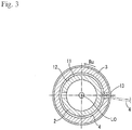
- the linear member 4 is inserted into both grooves 11 and 12, as shown in Figs. 1 and 3 .
- the lubricant oil is injected from an oil passage 13 formed between a hole (not shown) formed in the cylinder head and the outer periphery of the housing 3 into the hydraulic lash adjuster 1 equipped with the linear member 4.
- the lubrication oil is injected into the first and the second grooves 11 and 12, a space between the plunger 2, and into the interior of the housing 3 via a hole 2f formed in the plunger 2 and communicated with the interior.
- the width of the linear member 4 in a radial direction of the plunger 2 and the housing 3 linear member 4 is larger than either depth of the first groove 11 or the second groove 12.
- the linear member 4 occupies spaces that belong to the first groove 11 and the second groove 12, thereby preventing the plunger 2 from dropping out of the housing 3.
- a minute clearance d0 (not shown) between the outer periphery 9 of the plunger 2 and the inner periphery 10 of the housing 3 is 0.01, the depth d1 of the first groove 11 shown in Fig.
- the diameter of the linear member 4 is equal to d0+d1+d2, as in the present example, in order to allow the linear member 4 to exhibit a maximum stopping effect when in contact simultaneously with the first groove 11 as well as the second groove 12.
- Leading ends and tailing ends of the first groove 11 and the second groove 12 have slopes inclined with respect to the bottoms 11a and 12a of the grooves 11 and 12, respectively, in such a way that the apertures of the grooves (that is, axial lengths of the grooves) widen from their bottoms towards their upper open ends, as shown in Fig. 3 .
- the linear member 4 can move between two boundaries 11b and 11c or between two boundaries 12b and 12c, where the boundaries 11b and 11c are boundaries between the bottom 11a of the first groove 11 and its slopes, while the boundaries 12b and 12c are boundaries between the bottom 12a of the second groove 12 and their slopes.
- the cross sectional shape of the linear member 4 is not limited to a circle, and in fact a linear member of any transverse cross section can be used.
- one of the first groove 11 and the second groove 12 may have a shape that fits the outer profile of the linear member 4, so as to prohibit the axial movement of the linear member 4 along the center axis L0.
- the linear member 4 may be inserted through the oil supply passage 13 into a first and a second groove 11 and 12, respectively, which are formed to communicate with the oil supply passage 13 but extend only partially along the circumference of the plunger 2 and the housing 3.
- a dropout preventing mechanism 14 for stopping the plunger 2 from dropping out of the housing 3 will be now described If the plunger 2 happens to extend towards the leading end of the housing 3 (in the upward direction) due to wobbling of the plunger 2 in the housing 3 during its transportation, the linear member 4 is sandwiched between the lower inclined portion 11e of the groove 11 and the upper inclined portion 12d of the second groove 12 of the housing 3. As a consequence, the plunger 2 cannot extend any more, and is held within the housing 3.
Landscapes
- Engineering & Computer Science (AREA)
- Mechanical Engineering (AREA)
- General Engineering & Computer Science (AREA)
- Physics & Mathematics (AREA)
- Fluid Mechanics (AREA)
- Valve-Gear Or Valve Arrangements (AREA)
Claims (4)
- Verfahren zum Herstellen eines hydraulischen Spieleinstellers (1) enthaltend
ein zylindrisches Gehäuse (3) mit einem Boden,
einen Kolben (2), der in dem Gehäuse (3) gehalten wird, wobei ein Außenumfang (9) des Kolbens (2) in Kontakt mit einem inneren Umfang (10) des Gehäuses (3) steht,
eine erste Umfangsnut (11), die in dem äußeren Umfang (9) des Kolbens (2) ausgebildet ist,
eine zweite Umfangsnut (12), die in dem inneren Umfang (10) des Gehäuses (3) gegenüber der ersten Nut (11) ausgebildet ist, und
einen Ausfallverhinderungs-Mechanismus zum Verhindern, dass der Kolben (2) aus dem Gehäuse (3) herausfällt,
Ausbilden eines Linearelement-Einsetzlochs (13), das von einem Außenumfang (15) zu dem Innenumfang (10) des Gehäuses (3) durchdringt und mit einem zwischen der ersten und der zweiten Nut (11, 12) gebildeten Raum in Verbindung steht; wobei das Verfahren dadurch gekennzeichnet ist, dass es umfasst:
Einführen eines flexiblen linearen Elements (4) in die erste und die zweite Nut (11, 12) durch das Linearelement-Einsetzloch (13). - Verfahren zur Herstellung des hydraulischen Spieleinstellers (1) nach Anspruch 1, wobei
wenigstens eine der ersten und der zweiten Nut (11, 12) eine längliche Nut ist, die sich in der Richtung der Mittelachse der Spielausgleichsvorrichtung erstreckt, so dass
die eine Nut eine axiale Länge (d4, d5) aufweist, die größer als eine maximale bewegbare Distanz (d6) des Kolbens (2) relativ zu dem Gehäuse (3) während des Einstellens eines Ventilspiels ist. - Verfahren zur Herstellung des hydraulischen Spieleinstellers (1) nach Anspruch 1 oder Anspruch 2, wobei
das Linearelement-Einsetzloch (13) ein Ölzufuhrkanal ist. - Verfahren zur Herstellung des hydraulischen Spieleinstellers (1) nach Anspruch 1 oder Anspruch 2, wobei
die erste und die zweite Nut (11, 12) sich vollständig um die jeweiligen Umfänge des Gehäuses (3) und des Kolbens (2) herum erstrecken und
das lineare Element (4) vollständig um den Kolben (2) herum und in dem Raum angeordnet ist, der durch die erste und die zweite Nut (11, 12) gebildet wird.
Applications Claiming Priority (1)
| Application Number | Priority Date | Filing Date | Title |
|---|---|---|---|
| PCT/JP2013/072315 WO2015025385A1 (ja) | 2013-08-21 | 2013-08-21 | 油圧式ラッシュアジャスタ |
Publications (3)
| Publication Number | Publication Date |
|---|---|
| EP3037632A1 EP3037632A1 (de) | 2016-06-29 |
| EP3037632A4 EP3037632A4 (de) | 2017-04-26 |
| EP3037632B1 true EP3037632B1 (de) | 2019-03-20 |
Family
ID=52483195
Family Applications (1)
| Application Number | Title | Priority Date | Filing Date |
|---|---|---|---|
| EP13891963.4A Not-in-force EP3037632B1 (de) | 2013-08-21 | 2013-08-21 | Verfahren zur herstellung eines hydraulikspielausgleichselements |
Country Status (7)
| Country | Link |
|---|---|
| US (1) | US10301979B2 (de) |
| EP (1) | EP3037632B1 (de) |
| JP (1) | JP6153615B2 (de) |
| KR (1) | KR101823144B1 (de) |
| CN (1) | CN105765182B (de) |
| CA (1) | CA2921947C (de) |
| WO (1) | WO2015025385A1 (de) |
Families Citing this family (2)
| Publication number | Priority date | Publication date | Assignee | Title |
|---|---|---|---|---|
| US11237675B2 (en) * | 2017-08-22 | 2022-02-01 | Dongwoo Fine-Chem Co., Ltd. | Touch sensor and image display device including the same |
| CN116771460B (zh) * | 2023-08-17 | 2023-11-07 | 潍坊力创电子科技有限公司 | 液压全升程连续可变气门系统 |
Family Cites Families (16)
| Publication number | Priority date | Publication date | Assignee | Title |
|---|---|---|---|---|
| DE482512C (de) * | 1929-09-16 | Julius Bertram | Kugelgelenk mit Federring | |
| DE497940C (de) * | 1929-07-24 | 1930-05-15 | Julius Bertram | Kugelgelenk mit Federring |
| GB538952A (en) | 1940-02-17 | 1941-08-22 | Eaton Mfg Co | Improvements in or relating to hydraulic means for automatically taking up clearance in valve-actuating tappets |
| IT993729B (it) * | 1973-08-09 | 1975-09-30 | Stabilimenti Meccanici Vm Spa | Assieme biella pistone |
| DE2652154A1 (de) * | 1976-11-16 | 1978-05-18 | Motomak | Hydraulisches spielausgleichselement fuer verbrennungsmotoren |
| JPS58186106U (ja) * | 1982-06-08 | 1983-12-10 | 本田技研工業株式会社 | 油圧式ラツシユアジヤスタ |
| JP3194776B2 (ja) | 1992-03-25 | 2001-08-06 | オリンパス光学工業株式会社 | 体内留置チューブ |
| JP3607373B2 (ja) * | 1995-07-17 | 2005-01-05 | ジヤトコ株式会社 | 自動変速機の組立方法 |
| DE19529044A1 (de) * | 1995-08-08 | 1997-02-13 | Schaeffler Waelzlager Kg | Hydraulisches Spielausgleichselement für eine Ventilsteuerung einer Brennkraftmaschine |
| JP2006322438A (ja) * | 2005-05-20 | 2006-11-30 | Toyota Motor Corp | 内燃機関の油圧式バルブラッシュアジャスタ |
| JP4731521B2 (ja) | 2007-06-04 | 2011-07-27 | 株式会社オティックス | ラッシュアジャスタ及びそのリテーナの組付方法 |
| DE102008048515A1 (de) * | 2008-09-23 | 2010-03-25 | Schaeffler Kg | Winkelgelenk |
| KR101305026B1 (ko) * | 2009-06-10 | 2013-09-06 | 니탄 밸브 가부시키가이샤 | 내연기관용 유압 래시 어저스터 |
| JP5355296B2 (ja) * | 2009-08-18 | 2013-11-27 | 株式会社オティックス | ロッカアームユニット |
| JP2011141006A (ja) * | 2010-01-08 | 2011-07-21 | Ntn Corp | 油圧式オートテンショナ |
| DE102011002592A1 (de) * | 2011-01-12 | 2012-07-12 | Schaeffler Technologies Gmbh & Co. Kg | Winkelgelenk |
-
2013
- 2013-08-21 EP EP13891963.4A patent/EP3037632B1/de not_active Not-in-force
- 2013-08-21 JP JP2015532620A patent/JP6153615B2/ja not_active Expired - Fee Related
- 2013-08-21 WO PCT/JP2013/072315 patent/WO2015025385A1/ja not_active Ceased
- 2013-08-21 CA CA2921947A patent/CA2921947C/en not_active Expired - Fee Related
- 2013-08-21 US US14/913,111 patent/US10301979B2/en not_active Expired - Fee Related
- 2013-08-21 KR KR1020157034221A patent/KR101823144B1/ko not_active Expired - Fee Related
- 2013-08-21 CN CN201380077664.1A patent/CN105765182B/zh not_active Expired - Fee Related
Non-Patent Citations (1)
| Title |
|---|
| None * |
Also Published As
| Publication number | Publication date |
|---|---|
| US10301979B2 (en) | 2019-05-28 |
| KR20160045629A (ko) | 2016-04-27 |
| CA2921947C (en) | 2018-07-10 |
| KR101823144B1 (ko) | 2018-01-30 |
| WO2015025385A1 (ja) | 2015-02-26 |
| US20160208660A1 (en) | 2016-07-21 |
| JPWO2015025385A1 (ja) | 2017-03-02 |
| EP3037632A4 (de) | 2017-04-26 |
| CN105765182A (zh) | 2016-07-13 |
| CA2921947A1 (en) | 2015-02-26 |
| JP6153615B2 (ja) | 2017-07-05 |
| CN105765182B (zh) | 2019-12-03 |
| EP3037632A1 (de) | 2016-06-29 |
Similar Documents
| Publication | Publication Date | Title |
|---|---|---|
| EP2677124B1 (de) | Rollenstössel für Verbrennungsmotor | |
| EP2853738B1 (de) | Mechanisches System, Einspritzpumpe und Ventilaktor mit einem solchen mechanischen System und Herstellungsverfahren | |
| EP3073066B1 (de) | Nockenfolger, einspritzpumpe und ventilaktuator mit solch einem nockenfolger und herstellungsverfahren | |
| US9933062B2 (en) | Mechanical system forming a cam follower or a rocker arm | |
| EP2960446A1 (de) | Mechanisches System, das einen Nockenfolger oder einen Kipphebel ausbildet | |
| US20150247585A1 (en) | Solenoid valve and manufacturing method of the same | |
| EP3081771B1 (de) | Nockenfolger, einspritzpumpe und ventilaktuator mit solch einem nockenfolger und herstellungsverfahren | |
| CN105090406B (zh) | 适于装备形成凸轮或摇臂的机械系统的制造辊子的方法 | |
| US20160091074A1 (en) | Mechanical system forming a cam follower or a rocker arm | |
| US20170145877A1 (en) | Cam follower roller device with lubricant supply holes and lubricating method | |
| EP3037632B1 (de) | Verfahren zur herstellung eines hydraulikspielausgleichselements | |
| JP4749399B2 (ja) | 内燃機関のピストン | |
| EP3098402B1 (de) | Hydraulikspielausgleichselement | |
| US20160091075A1 (en) | Mechanical system forming a cam follower or a rocker arm | |
| US10190444B2 (en) | Cam follower roller device with washer | |
| US9334767B2 (en) | Roller lifter lubrication guide | |
| EP3526450B1 (de) | Hülsen für eine hydraulikspielausgleichsanordnung | |
| WO2012153102A1 (en) | A connection member for interconnecting a rocker arm and a push rod | |
| EP3153702B1 (de) | Pumpanordnung |
Legal Events
| Date | Code | Title | Description |
|---|---|---|---|
| PUAI | Public reference made under article 153(3) epc to a published international application that has entered the european phase |
Free format text: ORIGINAL CODE: 0009012 |
|
| 17P | Request for examination filed |
Effective date: 20160225 |
|
| AK | Designated contracting states |
Kind code of ref document: A1 Designated state(s): AL AT BE BG CH CY CZ DE DK EE ES FI FR GB GR HR HU IE IS IT LI LT LU LV MC MK MT NL NO PL PT RO RS SE SI SK SM TR |
|
| AX | Request for extension of the european patent |
Extension state: BA ME |
|
| DAX | Request for extension of the european patent (deleted) | ||
| A4 | Supplementary search report drawn up and despatched |
Effective date: 20170329 |
|
| RIC1 | Information provided on ipc code assigned before grant |
Ipc: F15B 15/24 20060101ALI20170323BHEP Ipc: F15B 15/14 20060101ALI20170323BHEP Ipc: F01L 1/24 20060101ALI20170323BHEP Ipc: F01L 1/255 20060101AFI20170323BHEP |
|
| GRAP | Despatch of communication of intention to grant a patent |
Free format text: ORIGINAL CODE: EPIDOSNIGR1 |
|
| STAA | Information on the status of an ep patent application or granted ep patent |
Free format text: STATUS: GRANT OF PATENT IS INTENDED |
|
| INTG | Intention to grant announced |
Effective date: 20180509 |
|
| GRAS | Grant fee paid |
Free format text: ORIGINAL CODE: EPIDOSNIGR3 |
|
| GRAJ | Information related to disapproval of communication of intention to grant by the applicant or resumption of examination proceedings by the epo deleted |
Free format text: ORIGINAL CODE: EPIDOSDIGR1 |
|
| GRAL | Information related to payment of fee for publishing/printing deleted |
Free format text: ORIGINAL CODE: EPIDOSDIGR3 |
|
| STAA | Information on the status of an ep patent application or granted ep patent |
Free format text: STATUS: REQUEST FOR EXAMINATION WAS MADE |
|
| GRAP | Despatch of communication of intention to grant a patent |
Free format text: ORIGINAL CODE: EPIDOSNIGR1 |
|
| STAA | Information on the status of an ep patent application or granted ep patent |
Free format text: STATUS: GRANT OF PATENT IS INTENDED |
|
| INTC | Intention to grant announced (deleted) | ||
| INTG | Intention to grant announced |
Effective date: 20181002 |
|
| GRAA | (expected) grant |
Free format text: ORIGINAL CODE: 0009210 |
|
| STAA | Information on the status of an ep patent application or granted ep patent |
Free format text: STATUS: THE PATENT HAS BEEN GRANTED |
|
| AK | Designated contracting states |
Kind code of ref document: B1 Designated state(s): AL AT BE BG CH CY CZ DE DK EE ES FI FR GB GR HR HU IE IS IT LI LT LU LV MC MK MT NL NO PL PT RO RS SE SI SK SM TR |
|
| REG | Reference to a national code |
Ref country code: GB Ref legal event code: FG4D |
|
| REG | Reference to a national code |
Ref country code: CH Ref legal event code: EP |
|
| REG | Reference to a national code |
Ref country code: DE Ref legal event code: R096 Ref document number: 602013052784 Country of ref document: DE |
|
| REG | Reference to a national code |
Ref country code: AT Ref legal event code: REF Ref document number: 1110751 Country of ref document: AT Kind code of ref document: T Effective date: 20190415 |
|
| REG | Reference to a national code |
Ref country code: IE Ref legal event code: FG4D |
|
| REG | Reference to a national code |
Ref country code: NL Ref legal event code: MP Effective date: 20190320 |
|
| PG25 | Lapsed in a contracting state [announced via postgrant information from national office to epo] |
Ref country code: LT Free format text: LAPSE BECAUSE OF FAILURE TO SUBMIT A TRANSLATION OF THE DESCRIPTION OR TO PAY THE FEE WITHIN THE PRESCRIBED TIME-LIMIT Effective date: 20190320 Ref country code: FI Free format text: LAPSE BECAUSE OF FAILURE TO SUBMIT A TRANSLATION OF THE DESCRIPTION OR TO PAY THE FEE WITHIN THE PRESCRIBED TIME-LIMIT Effective date: 20190320 Ref country code: NO Free format text: LAPSE BECAUSE OF FAILURE TO SUBMIT A TRANSLATION OF THE DESCRIPTION OR TO PAY THE FEE WITHIN THE PRESCRIBED TIME-LIMIT Effective date: 20190620 Ref country code: SE Free format text: LAPSE BECAUSE OF FAILURE TO SUBMIT A TRANSLATION OF THE DESCRIPTION OR TO PAY THE FEE WITHIN THE PRESCRIBED TIME-LIMIT Effective date: 20190320 |
|
| REG | Reference to a national code |
Ref country code: LT Ref legal event code: MG4D |
|
| PG25 | Lapsed in a contracting state [announced via postgrant information from national office to epo] |
Ref country code: BG Free format text: LAPSE BECAUSE OF FAILURE TO SUBMIT A TRANSLATION OF THE DESCRIPTION OR TO PAY THE FEE WITHIN THE PRESCRIBED TIME-LIMIT Effective date: 20190620 Ref country code: GR Free format text: LAPSE BECAUSE OF FAILURE TO SUBMIT A TRANSLATION OF THE DESCRIPTION OR TO PAY THE FEE WITHIN THE PRESCRIBED TIME-LIMIT Effective date: 20190621 Ref country code: LV Free format text: LAPSE BECAUSE OF FAILURE TO SUBMIT A TRANSLATION OF THE DESCRIPTION OR TO PAY THE FEE WITHIN THE PRESCRIBED TIME-LIMIT Effective date: 20190320 Ref country code: RS Free format text: LAPSE BECAUSE OF FAILURE TO SUBMIT A TRANSLATION OF THE DESCRIPTION OR TO PAY THE FEE WITHIN THE PRESCRIBED TIME-LIMIT Effective date: 20190320 Ref country code: HR Free format text: LAPSE BECAUSE OF FAILURE TO SUBMIT A TRANSLATION OF THE DESCRIPTION OR TO PAY THE FEE WITHIN THE PRESCRIBED TIME-LIMIT Effective date: 20190320 Ref country code: NL Free format text: LAPSE BECAUSE OF FAILURE TO SUBMIT A TRANSLATION OF THE DESCRIPTION OR TO PAY THE FEE WITHIN THE PRESCRIBED TIME-LIMIT Effective date: 20190320 |
|
| REG | Reference to a national code |
Ref country code: AT Ref legal event code: MK05 Ref document number: 1110751 Country of ref document: AT Kind code of ref document: T Effective date: 20190320 |
|
| PG25 | Lapsed in a contracting state [announced via postgrant information from national office to epo] |
Ref country code: RO Free format text: LAPSE BECAUSE OF FAILURE TO SUBMIT A TRANSLATION OF THE DESCRIPTION OR TO PAY THE FEE WITHIN THE PRESCRIBED TIME-LIMIT Effective date: 20190320 Ref country code: SK Free format text: LAPSE BECAUSE OF FAILURE TO SUBMIT A TRANSLATION OF THE DESCRIPTION OR TO PAY THE FEE WITHIN THE PRESCRIBED TIME-LIMIT Effective date: 20190320 Ref country code: AL Free format text: LAPSE BECAUSE OF FAILURE TO SUBMIT A TRANSLATION OF THE DESCRIPTION OR TO PAY THE FEE WITHIN THE PRESCRIBED TIME-LIMIT Effective date: 20190320 Ref country code: CZ Free format text: LAPSE BECAUSE OF FAILURE TO SUBMIT A TRANSLATION OF THE DESCRIPTION OR TO PAY THE FEE WITHIN THE PRESCRIBED TIME-LIMIT Effective date: 20190320 Ref country code: ES Free format text: LAPSE BECAUSE OF FAILURE TO SUBMIT A TRANSLATION OF THE DESCRIPTION OR TO PAY THE FEE WITHIN THE PRESCRIBED TIME-LIMIT Effective date: 20190320 Ref country code: PT Free format text: LAPSE BECAUSE OF FAILURE TO SUBMIT A TRANSLATION OF THE DESCRIPTION OR TO PAY THE FEE WITHIN THE PRESCRIBED TIME-LIMIT Effective date: 20190720 Ref country code: EE Free format text: LAPSE BECAUSE OF FAILURE TO SUBMIT A TRANSLATION OF THE DESCRIPTION OR TO PAY THE FEE WITHIN THE PRESCRIBED TIME-LIMIT Effective date: 20190320 |
|
| PG25 | Lapsed in a contracting state [announced via postgrant information from national office to epo] |
Ref country code: SM Free format text: LAPSE BECAUSE OF FAILURE TO SUBMIT A TRANSLATION OF THE DESCRIPTION OR TO PAY THE FEE WITHIN THE PRESCRIBED TIME-LIMIT Effective date: 20190320 Ref country code: PL Free format text: LAPSE BECAUSE OF FAILURE TO SUBMIT A TRANSLATION OF THE DESCRIPTION OR TO PAY THE FEE WITHIN THE PRESCRIBED TIME-LIMIT Effective date: 20190320 |
|
| PG25 | Lapsed in a contracting state [announced via postgrant information from national office to epo] |
Ref country code: IS Free format text: LAPSE BECAUSE OF FAILURE TO SUBMIT A TRANSLATION OF THE DESCRIPTION OR TO PAY THE FEE WITHIN THE PRESCRIBED TIME-LIMIT Effective date: 20190720 Ref country code: AT Free format text: LAPSE BECAUSE OF FAILURE TO SUBMIT A TRANSLATION OF THE DESCRIPTION OR TO PAY THE FEE WITHIN THE PRESCRIBED TIME-LIMIT Effective date: 20190320 |
|
| REG | Reference to a national code |
Ref country code: DE Ref legal event code: R097 Ref document number: 602013052784 Country of ref document: DE |
|
| PLBE | No opposition filed within time limit |
Free format text: ORIGINAL CODE: 0009261 |
|
| STAA | Information on the status of an ep patent application or granted ep patent |
Free format text: STATUS: NO OPPOSITION FILED WITHIN TIME LIMIT |
|
| PG25 | Lapsed in a contracting state [announced via postgrant information from national office to epo] |
Ref country code: DK Free format text: LAPSE BECAUSE OF FAILURE TO SUBMIT A TRANSLATION OF THE DESCRIPTION OR TO PAY THE FEE WITHIN THE PRESCRIBED TIME-LIMIT Effective date: 20190320 |
|
| 26N | No opposition filed |
Effective date: 20200102 |
|
| PG25 | Lapsed in a contracting state [announced via postgrant information from national office to epo] |
Ref country code: SI Free format text: LAPSE BECAUSE OF FAILURE TO SUBMIT A TRANSLATION OF THE DESCRIPTION OR TO PAY THE FEE WITHIN THE PRESCRIBED TIME-LIMIT Effective date: 20190320 |
|
| PG25 | Lapsed in a contracting state [announced via postgrant information from national office to epo] |
Ref country code: TR Free format text: LAPSE BECAUSE OF FAILURE TO SUBMIT A TRANSLATION OF THE DESCRIPTION OR TO PAY THE FEE WITHIN THE PRESCRIBED TIME-LIMIT Effective date: 20190320 |
|
| PG25 | Lapsed in a contracting state [announced via postgrant information from national office to epo] |
Ref country code: MC Free format text: LAPSE BECAUSE OF FAILURE TO SUBMIT A TRANSLATION OF THE DESCRIPTION OR TO PAY THE FEE WITHIN THE PRESCRIBED TIME-LIMIT Effective date: 20190320 Ref country code: CH Free format text: LAPSE BECAUSE OF NON-PAYMENT OF DUE FEES Effective date: 20190831 Ref country code: LU Free format text: LAPSE BECAUSE OF NON-PAYMENT OF DUE FEES Effective date: 20190821 Ref country code: LI Free format text: LAPSE BECAUSE OF NON-PAYMENT OF DUE FEES Effective date: 20190831 |
|
| REG | Reference to a national code |
Ref country code: BE Ref legal event code: MM Effective date: 20190831 |
|
| PG25 | Lapsed in a contracting state [announced via postgrant information from national office to epo] |
Ref country code: IE Free format text: LAPSE BECAUSE OF NON-PAYMENT OF DUE FEES Effective date: 20190821 |
|
| PG25 | Lapsed in a contracting state [announced via postgrant information from national office to epo] |
Ref country code: BE Free format text: LAPSE BECAUSE OF NON-PAYMENT OF DUE FEES Effective date: 20190831 |
|
| PGFP | Annual fee paid to national office [announced via postgrant information from national office to epo] |
Ref country code: DE Payment date: 20200819 Year of fee payment: 8 Ref country code: FR Payment date: 20200821 Year of fee payment: 8 Ref country code: GB Payment date: 20200826 Year of fee payment: 8 |
|
| PGFP | Annual fee paid to national office [announced via postgrant information from national office to epo] |
Ref country code: IT Payment date: 20200826 Year of fee payment: 8 |
|
| PG25 | Lapsed in a contracting state [announced via postgrant information from national office to epo] |
Ref country code: CY Free format text: LAPSE BECAUSE OF FAILURE TO SUBMIT A TRANSLATION OF THE DESCRIPTION OR TO PAY THE FEE WITHIN THE PRESCRIBED TIME-LIMIT Effective date: 20190320 |
|
| PG25 | Lapsed in a contracting state [announced via postgrant information from national office to epo] |
Ref country code: MT Free format text: LAPSE BECAUSE OF FAILURE TO SUBMIT A TRANSLATION OF THE DESCRIPTION OR TO PAY THE FEE WITHIN THE PRESCRIBED TIME-LIMIT Effective date: 20190320 Ref country code: HU Free format text: LAPSE BECAUSE OF FAILURE TO SUBMIT A TRANSLATION OF THE DESCRIPTION OR TO PAY THE FEE WITHIN THE PRESCRIBED TIME-LIMIT; INVALID AB INITIO Effective date: 20130821 |
|
| REG | Reference to a national code |
Ref country code: DE Ref legal event code: R119 Ref document number: 602013052784 Country of ref document: DE |
|
| GBPC | Gb: european patent ceased through non-payment of renewal fee |
Effective date: 20210821 |
|
| PG25 | Lapsed in a contracting state [announced via postgrant information from national office to epo] |
Ref country code: MK Free format text: LAPSE BECAUSE OF FAILURE TO SUBMIT A TRANSLATION OF THE DESCRIPTION OR TO PAY THE FEE WITHIN THE PRESCRIBED TIME-LIMIT Effective date: 20190320 |
|
| PG25 | Lapsed in a contracting state [announced via postgrant information from national office to epo] |
Ref country code: IT Free format text: LAPSE BECAUSE OF NON-PAYMENT OF DUE FEES Effective date: 20210821 Ref country code: GB Free format text: LAPSE BECAUSE OF NON-PAYMENT OF DUE FEES Effective date: 20210821 Ref country code: FR Free format text: LAPSE BECAUSE OF NON-PAYMENT OF DUE FEES Effective date: 20210831 Ref country code: DE Free format text: LAPSE BECAUSE OF NON-PAYMENT OF DUE FEES Effective date: 20220301 |