EP3038197A1 - Substrat céramique pour un élément électrochimique, procédé permettant de fabriquer ce dernier, pile à combustible, et empilement de piles à combustible - Google Patents
Substrat céramique pour un élément électrochimique, procédé permettant de fabriquer ce dernier, pile à combustible, et empilement de piles à combustible Download PDFInfo
- Publication number
- EP3038197A1 EP3038197A1 EP14837601.5A EP14837601A EP3038197A1 EP 3038197 A1 EP3038197 A1 EP 3038197A1 EP 14837601 A EP14837601 A EP 14837601A EP 3038197 A1 EP3038197 A1 EP 3038197A1
- Authority
- EP
- European Patent Office
- Prior art keywords
- ceramic
- thermal
- expansion
- layer
- electrochemical element
- Prior art date
- Legal status (The legal status is an assumption and is not a legal conclusion. Google has not performed a legal analysis and makes no representation as to the accuracy of the status listed.)
- Withdrawn
Links
- 239000000919 ceramic Substances 0.000 title claims abstract description 137
- 239000000758 substrate Substances 0.000 title claims abstract description 52
- 239000000446 fuel Substances 0.000 title claims description 83
- 238000004519 manufacturing process Methods 0.000 title claims description 12
- 238000000034 method Methods 0.000 title claims description 11
- 239000000463 material Substances 0.000 claims abstract description 74
- 238000010304 firing Methods 0.000 claims description 19
- 229910010293 ceramic material Inorganic materials 0.000 claims description 7
- BQENXCOZCUHKRE-UHFFFAOYSA-N [La+3].[La+3].[O-][Mn]([O-])=O.[O-][Mn]([O-])=O.[O-][Mn]([O-])=O Chemical compound [La+3].[La+3].[O-][Mn]([O-])=O.[O-][Mn]([O-])=O.[O-][Mn]([O-])=O BQENXCOZCUHKRE-UHFFFAOYSA-N 0.000 claims description 3
- 230000035882 stress Effects 0.000 abstract description 16
- 230000008646 thermal stress Effects 0.000 abstract description 13
- 239000007787 solid Substances 0.000 description 14
- 230000000052 comparative effect Effects 0.000 description 10
- 239000003792 electrolyte Substances 0.000 description 10
- 230000015572 biosynthetic process Effects 0.000 description 7
- 239000002737 fuel gas Substances 0.000 description 7
- 239000007789 gas Substances 0.000 description 7
- 239000007800 oxidant agent Substances 0.000 description 7
- 230000001590 oxidative effect Effects 0.000 description 7
- 229910001233 yttria-stabilized zirconia Inorganic materials 0.000 description 7
- 238000000926 separation method Methods 0.000 description 6
- 229910002076 stabilized zirconia Inorganic materials 0.000 description 6
- 229910021526 gadolinium-doped ceria Inorganic materials 0.000 description 5
- 229910002077 partially stabilized zirconia Inorganic materials 0.000 description 5
- 238000010248 power generation Methods 0.000 description 5
- 101001017896 Homo sapiens U6 snRNA-associated Sm-like protein LSm1 Proteins 0.000 description 4
- 101001017904 Homo sapiens U6 snRNA-associated Sm-like protein LSm2 Proteins 0.000 description 4
- 101001017894 Homo sapiens U6 snRNA-associated Sm-like protein LSm3 Proteins 0.000 description 4
- 102100033314 U6 snRNA-associated Sm-like protein LSm1 Human genes 0.000 description 4
- 102100033309 U6 snRNA-associated Sm-like protein LSm2 Human genes 0.000 description 4
- 102100033313 U6 snRNA-associated Sm-like protein LSm3 Human genes 0.000 description 4
- 239000000203 mixture Substances 0.000 description 4
- PXHVJJICTQNCMI-UHFFFAOYSA-N Nickel Chemical compound [Ni] PXHVJJICTQNCMI-UHFFFAOYSA-N 0.000 description 3
- 241000968352 Scandia <hydrozoan> Species 0.000 description 3
- HJGMWXTVGKLUAQ-UHFFFAOYSA-N oxygen(2-);scandium(3+) Chemical compound [O-2].[O-2].[O-2].[Sc+3].[Sc+3] HJGMWXTVGKLUAQ-UHFFFAOYSA-N 0.000 description 3
- 239000002002 slurry Substances 0.000 description 3
- OKTJSMMVPCPJKN-UHFFFAOYSA-N Carbon Chemical compound [C] OKTJSMMVPCPJKN-UHFFFAOYSA-N 0.000 description 2
- MCMNRKCIXSYSNV-UHFFFAOYSA-N Zirconium dioxide Chemical compound O=[Zr]=O MCMNRKCIXSYSNV-UHFFFAOYSA-N 0.000 description 2
- 239000011230 binding agent Substances 0.000 description 2
- 239000004020 conductor Substances 0.000 description 2
- 230000000694 effects Effects 0.000 description 2
- 238000011156 evaluation Methods 0.000 description 2
- 239000000843 powder Substances 0.000 description 2
- 239000011347 resin Substances 0.000 description 2
- 229920005989 resin Polymers 0.000 description 2
- 239000002904 solvent Substances 0.000 description 2
- RUDFQVOCFDJEEF-UHFFFAOYSA-N yttrium(III) oxide Inorganic materials [O-2].[O-2].[O-2].[Y+3].[Y+3] RUDFQVOCFDJEEF-UHFFFAOYSA-N 0.000 description 2
- UGFAIRIUMAVXCW-UHFFFAOYSA-N Carbon monoxide Chemical compound [O+]#[C-] UGFAIRIUMAVXCW-UHFFFAOYSA-N 0.000 description 1
- MYMOFIZGZYHOMD-UHFFFAOYSA-N Dioxygen Chemical compound O=O MYMOFIZGZYHOMD-UHFFFAOYSA-N 0.000 description 1
- 229910002182 La0.7Sr0.3MnO3 Inorganic materials 0.000 description 1
- 229910002204 La0.8Sr0.2MnO3 Inorganic materials 0.000 description 1
- 229910026161 MgAl2O4 Inorganic materials 0.000 description 1
- PNEYBMLMFCGWSK-UHFFFAOYSA-N aluminium oxide Inorganic materials [O-2].[O-2].[O-2].[Al+3].[Al+3] PNEYBMLMFCGWSK-UHFFFAOYSA-N 0.000 description 1
- 239000003990 capacitor Substances 0.000 description 1
- 229910002091 carbon monoxide Inorganic materials 0.000 description 1
- 239000011195 cermet Substances 0.000 description 1
- 229910052729 chemical element Inorganic materials 0.000 description 1
- 229910052963 cobaltite Inorganic materials 0.000 description 1
- 239000000470 constituent Substances 0.000 description 1
- 238000005336 cracking Methods 0.000 description 1
- 229910001882 dioxygen Inorganic materials 0.000 description 1
- 238000010438 heat treatment Methods 0.000 description 1
- 229910052739 hydrogen Inorganic materials 0.000 description 1
- 239000001257 hydrogen Substances 0.000 description 1
- 125000004435 hydrogen atom Chemical class [H]* 0.000 description 1
- 229910003437 indium oxide Inorganic materials 0.000 description 1
- PJXISJQVUVHSOJ-UHFFFAOYSA-N indium(iii) oxide Chemical compound [O-2].[O-2].[O-2].[In+3].[In+3] PJXISJQVUVHSOJ-UHFFFAOYSA-N 0.000 description 1
- 229910000473 manganese(VI) oxide Inorganic materials 0.000 description 1
- 239000011159 matrix material Substances 0.000 description 1
- 238000005259 measurement Methods 0.000 description 1
- 229910052751 metal Inorganic materials 0.000 description 1
- 239000002184 metal Substances 0.000 description 1
- 229910052759 nickel Inorganic materials 0.000 description 1
- SIWVEOZUMHYXCS-UHFFFAOYSA-N oxo(oxoyttriooxy)yttrium Chemical compound O=[Y]O[Y]=O SIWVEOZUMHYXCS-UHFFFAOYSA-N 0.000 description 1
- 238000002360 preparation method Methods 0.000 description 1
- 229910052596 spinel Inorganic materials 0.000 description 1
- 239000011800 void material Substances 0.000 description 1
Images



Classifications
-
- H—ELECTRICITY
- H01—ELECTRIC ELEMENTS
- H01M—PROCESSES OR MEANS, e.g. BATTERIES, FOR THE DIRECT CONVERSION OF CHEMICAL ENERGY INTO ELECTRICAL ENERGY
- H01M8/00—Fuel cells; Manufacture thereof
- H01M8/02—Details
- H01M8/0202—Collectors; Separators, e.g. bipolar separators; Interconnectors
- H01M8/0204—Non-porous and characterised by the material
- H01M8/0215—Glass; Ceramic materials
-
- B—PERFORMING OPERATIONS; TRANSPORTING
- B32—LAYERED PRODUCTS
- B32B—LAYERED PRODUCTS, i.e. PRODUCTS BUILT-UP OF STRATA OF FLAT OR NON-FLAT, e.g. CELLULAR OR HONEYCOMB, FORM
- B32B18/00—Layered products essentially comprising ceramics, e.g. refractory products
-
- H—ELECTRICITY
- H01—ELECTRIC ELEMENTS
- H01M—PROCESSES OR MEANS, e.g. BATTERIES, FOR THE DIRECT CONVERSION OF CHEMICAL ENERGY INTO ELECTRICAL ENERGY
- H01M8/00—Fuel cells; Manufacture thereof
- H01M8/02—Details
- H01M8/0202—Collectors; Separators, e.g. bipolar separators; Interconnectors
- H01M8/0204—Non-porous and characterised by the material
- H01M8/0223—Composites
- H01M8/0228—Composites in the form of layered or coated products
-
- C—CHEMISTRY; METALLURGY
- C04—CEMENTS; CONCRETE; ARTIFICIAL STONE; CERAMICS; REFRACTORIES
- C04B—LIME, MAGNESIA; SLAG; CEMENTS; COMPOSITIONS THEREOF, e.g. MORTARS, CONCRETE OR LIKE BUILDING MATERIALS; ARTIFICIAL STONE; CERAMICS; REFRACTORIES; TREATMENT OF NATURAL STONE
- C04B2235/00—Aspects relating to ceramic starting mixtures or sintered ceramic products
- C04B2235/02—Composition of constituents of the starting material or of secondary phases of the final product
- C04B2235/30—Constituents and secondary phases not being of a fibrous nature
- C04B2235/32—Metal oxides, mixed metal oxides, or oxide-forming salts thereof, e.g. carbonates, nitrates, (oxy)hydroxides, chlorides
- C04B2235/3224—Rare earth oxide or oxide forming salts thereof, e.g. scandium oxide
- C04B2235/3225—Yttrium oxide or oxide-forming salts thereof
-
- C—CHEMISTRY; METALLURGY
- C04—CEMENTS; CONCRETE; ARTIFICIAL STONE; CERAMICS; REFRACTORIES
- C04B—LIME, MAGNESIA; SLAG; CEMENTS; COMPOSITIONS THEREOF, e.g. MORTARS, CONCRETE OR LIKE BUILDING MATERIALS; ARTIFICIAL STONE; CERAMICS; REFRACTORIES; TREATMENT OF NATURAL STONE
- C04B2235/00—Aspects relating to ceramic starting mixtures or sintered ceramic products
- C04B2235/02—Composition of constituents of the starting material or of secondary phases of the final product
- C04B2235/30—Constituents and secondary phases not being of a fibrous nature
- C04B2235/32—Metal oxides, mixed metal oxides, or oxide-forming salts thereof, e.g. carbonates, nitrates, (oxy)hydroxides, chlorides
- C04B2235/3231—Refractory metal oxides, their mixed metal oxides, or oxide-forming salts thereof
- C04B2235/3244—Zirconium oxides, zirconates, hafnium oxides, hafnates, or oxide-forming salts thereof
-
- C—CHEMISTRY; METALLURGY
- C04—CEMENTS; CONCRETE; ARTIFICIAL STONE; CERAMICS; REFRACTORIES
- C04B—LIME, MAGNESIA; SLAG; CEMENTS; COMPOSITIONS THEREOF, e.g. MORTARS, CONCRETE OR LIKE BUILDING MATERIALS; ARTIFICIAL STONE; CERAMICS; REFRACTORIES; TREATMENT OF NATURAL STONE
- C04B2235/00—Aspects relating to ceramic starting mixtures or sintered ceramic products
- C04B2235/60—Aspects relating to the preparation, properties or mechanical treatment of green bodies or pre-forms
- C04B2235/602—Making the green bodies or pre-forms by moulding
- C04B2235/6025—Tape casting, e.g. with a doctor blade
-
- C—CHEMISTRY; METALLURGY
- C04—CEMENTS; CONCRETE; ARTIFICIAL STONE; CERAMICS; REFRACTORIES
- C04B—LIME, MAGNESIA; SLAG; CEMENTS; COMPOSITIONS THEREOF, e.g. MORTARS, CONCRETE OR LIKE BUILDING MATERIALS; ARTIFICIAL STONE; CERAMICS; REFRACTORIES; TREATMENT OF NATURAL STONE
- C04B2235/00—Aspects relating to ceramic starting mixtures or sintered ceramic products
- C04B2235/70—Aspects relating to sintered or melt-casted ceramic products
- C04B2235/96—Properties of ceramic products, e.g. mechanical properties such as strength, toughness, wear resistance
- C04B2235/9607—Thermal properties, e.g. thermal expansion coefficient
-
- C—CHEMISTRY; METALLURGY
- C04—CEMENTS; CONCRETE; ARTIFICIAL STONE; CERAMICS; REFRACTORIES
- C04B—LIME, MAGNESIA; SLAG; CEMENTS; COMPOSITIONS THEREOF, e.g. MORTARS, CONCRETE OR LIKE BUILDING MATERIALS; ARTIFICIAL STONE; CERAMICS; REFRACTORIES; TREATMENT OF NATURAL STONE
- C04B2237/00—Aspects relating to ceramic laminates or to joining of ceramic articles with other articles by heating
- C04B2237/30—Composition of layers of ceramic laminates or of ceramic or metallic articles to be joined by heating, e.g. Si substrates
- C04B2237/32—Ceramic
- C04B2237/34—Oxidic
-
- C—CHEMISTRY; METALLURGY
- C04—CEMENTS; CONCRETE; ARTIFICIAL STONE; CERAMICS; REFRACTORIES
- C04B—LIME, MAGNESIA; SLAG; CEMENTS; COMPOSITIONS THEREOF, e.g. MORTARS, CONCRETE OR LIKE BUILDING MATERIALS; ARTIFICIAL STONE; CERAMICS; REFRACTORIES; TREATMENT OF NATURAL STONE
- C04B2237/00—Aspects relating to ceramic laminates or to joining of ceramic articles with other articles by heating
- C04B2237/30—Composition of layers of ceramic laminates or of ceramic or metallic articles to be joined by heating, e.g. Si substrates
- C04B2237/32—Ceramic
- C04B2237/34—Oxidic
- C04B2237/345—Refractory metal oxides
- C04B2237/348—Zirconia, hafnia, zirconates or hafnates
-
- C—CHEMISTRY; METALLURGY
- C04—CEMENTS; CONCRETE; ARTIFICIAL STONE; CERAMICS; REFRACTORIES
- C04B—LIME, MAGNESIA; SLAG; CEMENTS; COMPOSITIONS THEREOF, e.g. MORTARS, CONCRETE OR LIKE BUILDING MATERIALS; ARTIFICIAL STONE; CERAMICS; REFRACTORIES; TREATMENT OF NATURAL STONE
- C04B2237/00—Aspects relating to ceramic laminates or to joining of ceramic articles with other articles by heating
- C04B2237/50—Processing aspects relating to ceramic laminates or to the joining of ceramic articles with other articles by heating
- C04B2237/70—Forming laminates or joined articles comprising layers of a specific, unusual thickness
- C04B2237/704—Forming laminates or joined articles comprising layers of a specific, unusual thickness of one or more of the ceramic layers or articles
-
- H—ELECTRICITY
- H01—ELECTRIC ELEMENTS
- H01M—PROCESSES OR MEANS, e.g. BATTERIES, FOR THE DIRECT CONVERSION OF CHEMICAL ENERGY INTO ELECTRICAL ENERGY
- H01M8/00—Fuel cells; Manufacture thereof
- H01M8/10—Fuel cells with solid electrolytes
- H01M8/12—Fuel cells with solid electrolytes operating at high temperature, e.g. with stabilised ZrO2 electrolyte
- H01M2008/1293—Fuel cells with solid oxide electrolytes
-
- H—ELECTRICITY
- H01—ELECTRIC ELEMENTS
- H01M—PROCESSES OR MEANS, e.g. BATTERIES, FOR THE DIRECT CONVERSION OF CHEMICAL ENERGY INTO ELECTRICAL ENERGY
- H01M8/00—Fuel cells; Manufacture thereof
- H01M8/02—Details
- H01M8/0202—Collectors; Separators, e.g. bipolar separators; Interconnectors
- H01M8/0204—Non-porous and characterised by the material
- H01M8/0215—Glass; Ceramic materials
- H01M8/0217—Complex oxides, optionally doped, of the type AMO3, A being an alkaline earth metal or rare earth metal and M being a metal, e.g. perovskites
-
- Y—GENERAL TAGGING OF NEW TECHNOLOGICAL DEVELOPMENTS; GENERAL TAGGING OF CROSS-SECTIONAL TECHNOLOGIES SPANNING OVER SEVERAL SECTIONS OF THE IPC; TECHNICAL SUBJECTS COVERED BY FORMER USPC CROSS-REFERENCE ART COLLECTIONS [XRACs] AND DIGESTS
- Y02—TECHNOLOGIES OR APPLICATIONS FOR MITIGATION OR ADAPTATION AGAINST CLIMATE CHANGE
- Y02E—REDUCTION OF GREENHOUSE GAS [GHG] EMISSIONS, RELATED TO ENERGY GENERATION, TRANSMISSION OR DISTRIBUTION
- Y02E60/00—Enabling technologies; Technologies with a potential or indirect contribution to GHG emissions mitigation
- Y02E60/10—Energy storage using batteries
-
- Y—GENERAL TAGGING OF NEW TECHNOLOGICAL DEVELOPMENTS; GENERAL TAGGING OF CROSS-SECTIONAL TECHNOLOGIES SPANNING OVER SEVERAL SECTIONS OF THE IPC; TECHNICAL SUBJECTS COVERED BY FORMER USPC CROSS-REFERENCE ART COLLECTIONS [XRACs] AND DIGESTS
- Y02—TECHNOLOGIES OR APPLICATIONS FOR MITIGATION OR ADAPTATION AGAINST CLIMATE CHANGE
- Y02E—REDUCTION OF GREENHOUSE GAS [GHG] EMISSIONS, RELATED TO ENERGY GENERATION, TRANSMISSION OR DISTRIBUTION
- Y02E60/00—Enabling technologies; Technologies with a potential or indirect contribution to GHG emissions mitigation
- Y02E60/30—Hydrogen technology
- Y02E60/50—Fuel cells
-
- Y—GENERAL TAGGING OF NEW TECHNOLOGICAL DEVELOPMENTS; GENERAL TAGGING OF CROSS-SECTIONAL TECHNOLOGIES SPANNING OVER SEVERAL SECTIONS OF THE IPC; TECHNICAL SUBJECTS COVERED BY FORMER USPC CROSS-REFERENCE ART COLLECTIONS [XRACs] AND DIGESTS
- Y02—TECHNOLOGIES OR APPLICATIONS FOR MITIGATION OR ADAPTATION AGAINST CLIMATE CHANGE
- Y02P—CLIMATE CHANGE MITIGATION TECHNOLOGIES IN THE PRODUCTION OR PROCESSING OF GOODS
- Y02P70/00—Climate change mitigation technologies in the production process for final industrial or consumer products
- Y02P70/50—Manufacturing or production processes characterised by the final manufactured product
Definitions
- the present invention relates to a ceramic substrate for use in, e.g., a separator of an electrochemical element such as a fuel cell, a method for manufacturing the ceramic substrate, and a fuel cell and a fuel cell stack including the ceramic substrate.
- Patent Document 1 discloses a solid oxide fuel cell that uses a solid oxide electrolyte.
- the solid oxide electrolyte, separator, etc. constituting a cell of the fuel cell are formed from ceramics.
- Patent Document 1 WO 2008/044429
- Ceramic substrates for use in, e.g., separators in conventional electrochemical elements have the problem of low toughness, although the compressive strength is high. Therefore, there has been a problem that breakages due to thermal stress or mechanical stress are likely to be caused.
- An object of the present invention is to provide a ceramic substrate for an electrochemical element, which is unlikely to be broken when thermal stress or mechanical stress is applied, and a method for manufacturing the ceramic substrate.
- Another object of the present invention is to provide a fuel cell and a fuel cell stack that include the ceramic substrate for an electrochemical element.
- a ceramic substrate for an electrochemical element according to the present invention includes: a ceramic layer; and a high-thermal-expansion-coefficient material layer laminated on the surface of the ceramic layer, which has a higher coefficient of thermal expansion than the ceramic layer.
- compressive stress from the high-thermal-expansion-coefficient material layer is applied to the ceramic layer.
- the difference in coefficient of thermal expansion is 3 ppm or less between the ceramic layer and the high-thermal-expansion-coefficient material layer.
- the high-thermal-expansion-coefficient material layer is composed of a ceramic material containing lanthanum manganite as its main constituent.
- the high-thermal-expansion-coefficient material layer is a porous body.
- the ceramic substrate for an electrochemical element is a separator of an electrochemical element.
- the ceramic layer is a sheet-like ceramic layer.
- a method for manufacturing the ceramic substrate for an electrochemical element according to the present invention includes the steps of: preparing the ceramic layer; and integrating, on the surface of the ceramic layer, a high-thermal-expansion-coefficient material layer that has a higher coefficient of thermal expansion than the ceramic layer so that compressive stress is applied to the ceramic layer.
- the high-thermal-expansion-coefficient material layer is composed of a ceramic that has, after firing, a higher coefficient of thermal expansion than the ceramic layer, and the firing ceramic material constituting the high-thermal-expansion-coefficient material layer is laminated on the ceramic layer, and subjected to firing to integrate the high-thermal-expansion-coefficient material layer onto the ceramic layer.
- a fuel cell according to the present invention includes a separator and a cell of a fuel cell, and the separator is composed of the ceramic substrate for an electrochemical element, which is configured in accordance with the present invention.
- a fuel cell stack according to the present invention includes a plurality of cells of fuel cells stacked, and further includes a separator disposed between the cells of fuel cells stacked, and the separator is composed of the ceramic substrate for an electrochemical element, which is configured in accordance with the present invention.
- the strength of the ceramic layer is enhanced because compressive stress from the high-thermal-expansion-coefficient material layer is applied to the ceramic layer. Therefore, even when thermal stress or mechanical stress is applied, the ceramic substrate for an electrochemical element is unlikely to be broken.
- a fuel cell or a fuel cell stack that uses the ceramic substrate for an electrochemical element according to the present invention makes it possible to ensure that breakages due to thermal stress or the like are suppressed during manufacture or during use.
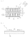
- FIG. 1 is an exploded perspective view of a fuel cell according to a first embodiment of the present invention
- FIG. 2 is a front cross-sectional view thereof.
- the solid oxide fuel cell 1 includes a first separator 10, a power generation element 30, and a second separator 50.
- the first separator 10, the power generation element 30, and the second separator 50 are laminated in this order as shown.
- first separator body 11 and second separator body 51 are composed of a ceramic substrate for an electrochemical element as an embodiment of the present invention.
- the first separator 10 has the first separator body 11 and a first flow path formation member 12.
- the first flow path formation member 12 has an oxidant gas flow path 12a formed for supplying air as an oxidant gas.
- the oxidant gas flow path 12a is partitioned by a plurality of separation parts 12c extending in the x direction. The upper surfaces of the respective flow path parts partitioned are closed by the first separator body 11.
- the first separator body 11 and the separation parts 12c have via hole electrodes 11c, 12cl formed.
- the via hole electrodes 11c and the via hole electrodes 12c1 are provided to overlap with each other.
- the first separator body 11 is provided with a slit 61 for the exit of an oxidant gas and a slit 62 for the passage of a fuel gas.
- the first separator body 11 includes a ceramic substrate for an electrochemical element as an embodiment of the present invention. More specifically, the first separator body 11 has a ceramic layer 11a, and a high-thermal-expansion-coefficient material layer 11b provided on one side of the ceramic layer 11a.
- the ceramic layer 11a can be formed from stabilized zirconia such as yttria stabilized zirconia, partially stabilized zirconia, or the like.
- stabilized zirconia examples include 10 mol% yttria stabilized zirconia (10YSZ) and 11 mol% scandia stabilized zirconia (11ScSZ).
- partially stabilized zirconia examples include 3 mol% yttria partially stabilized zirconia (3YSZ).
- the ceramic layer 11a may be formed from, for example, alumina or MgAl 2 O 4 .
- the high-thermal-expansion-coefficient material layer 11b can be formed from an appropriate material that is higher in coefficient of thermal expansion than the ceramic layer 11a.
- various ceramic materials can be used in a preferred manner.
- the materials can include, for example, LSM as a lanthanum-manganite based material, LSCF as a lanthanum-cobaltite based material, and gadolinium doped ceria (GDC).
- the high-thermal-expansion-coefficient material layer 11b is laminated on one side of the ceramic layer 11a as shown in FIG. 3 .
- the high-thermal-expansion-coefficient material layer 11b is laminated on the ceramic layer 11a so that compressive stress indicated by arrows A1 and A2 in the high-thermal-expansion-coefficient material layer 11b is applied to the ceramic layer 11a.
- This structure can be obtained by, for example, the following method.
- a ceramic green sheet for the ceramic layer 11a is prepared. On one side of the ceramic green sheet, another ceramic green sheet for forming the high-thermal-expansion-coefficient material layer 11b is laminated, and subjected to pressure bonding. Then, firing by heating can provide the high-thermal-expansion-coefficient material layer 11b and the ceramic layer 11a, and apply compressive stress from the high-thermal-expansion-coefficient material layer 11b to the ceramic layer 11a. The ceramic undergoes firing shrinkage during the firing. The firing shrinkage in the high-thermal-expansion-coefficient material layer 11b is greater than the firing shrinkage in the ceramic layer 11a. Therefore, compressive stress is applied to the ceramic layer 11a. When the stress from the pressure bonding is applied to the ceramic layer 11a, the mechanical strength of the ceramic layer 11a will be increased.
- the fracture toughness of the first separator body 11 and first separator 10 including the first separator body 11 can be enhanced effectively. Therefore, even when thermal stress is applied during manufacture or during use, the breakage of the first separator body 11 and first separator 10, and thus the breakage of the fuel cell 1 can be suppressed effectively.
- the second separator 50 also has a structure similar to the first separator 10. More specifically, the second separator 50 has a second separator body 51 and a second flow path formation member 52.
- the second separator body 51 has a ceramic layer 51a, and a high-thermal-expansion-coefficient material layer 51b provided on the lower surface of the ceramic layer 51a.
- the ceramic layer 51a is formed in the same way as the ceramic layer 11a described above.
- the high-thermal-expansion-coefficient material layer 51b is formed in the same way as the high-thermal-expansion-coefficient material layer 11b. Accordingly, the second separator body 51 is also unlikely to be broken even when thermal stress is applied.
- the second flow path formation member 52 has a fuel gas flow path 52a formed which extends in the Y direction. This fuel gas flow path 52a is partitioned by a plurality of separation parts 52c.
- the second separator body 51 also has a plurality of via hole electrodes 51c formed.
- the separation parts 52c are also provided with a plurality of via hole electrodes 52c1.
- the via hole electrodes 51c and the via hole electrodes 52c1 are arranged to overlap with each other.
- a feature of the fuel cell 1 according to the present embodiment is that the first and second separators 10, 50 have the ceramic layers 11a, 51a and the high-thermal expansion material layers 11b, 51b. Thus, as described above, breakages can be reliably suppressed when thermal stress is applied. The other configuration will be described below with reference to FIGS. 1 and 2 .
- the power generation element 30 refers to a part where an oxidant gas and a fuel gas react to generate power. Air, an oxygen gas, or the like can be used as the oxidant gas. As well known, hydrogen, carbon monoxide, or the like can be used as the fuel gas.
- the power generation element 30 has a solid oxide electrolyte layer 31.
- the solid oxide electrolyte layer 31 is preferably composed of a highly ion-conductive material. This solid oxide electrolyte layer 31 can be formed from stabilized zirconia, partially stabilized zirconia, or the like as mentioned previously.
- the solid oxide electrolyte layer 31 is sandwiched between an air electrode layer 32 and a fuel electrode layer 33.
- the air electrode layer 32 has an air electrode 32a.
- the air electrode 32a can be formed from scandia stabilized zirconia (ScSZ), Sn-doped indium oxide, PrCoO 3 -based oxide, or the LSM, LSCF, or LCM as mentioned previously.
- the fuel electrode layer 33 has a fuel electrode 33a.
- the fuel electrode 33a can be formed from, for example, NiO, yttria stabilized zirconia (YSZ), scandia stabilized zirconia (ScSZ), porous cermet of nickel metal, or the like.
- FIG. 4 is a schematic front cross-sectional view for explaining a fuel cell stack as a second embodiment of the present invention.
- a fuel cell stack 71 according to the present embodiment has cells 72, 72, 72 of fuel cells stacked with separators 73, 73 interposed therebetween.
- Each cell 72 of the fuel cell is configured, for example, in the same way as the fuel cell 1 according to the first embodiment.
- the voltage is increased with the plurality of cells 72, 72, 72, of the fuel cells stacked.
- the separator 73 includes a ceramic substrate for an electrochemical element as an embodiment of the present invention. More specifically, high-thermal-expansion-coefficient material layers 73b, 73c are laminated on both sides of a ceramic layer 73a.
- the high-thermal-expansion-coefficient material layers 73b, 73c are laminated so that compressive stress is applied to the ceramic layer 73a in a planar direction. Accordingly, in the present embodiment, the separator 73 is unlikely to be broken even when thermal stress is applied to the separator 73 during manufacture or during use. Therefore, the fuel cell stack 71 can be provided which has excellent reliability.
- the high-thermal-expansion-coefficient material layers may be formed on both surfaces of the ceramic layer for the ceramic substrate for an electrochemical element. More specifically, the position of the high thermal-expansion-coefficient material layer formed on the surface of the ceramic layer is not particularly limited.
- the high-thermal-expansion-coefficient material layer may be laminated in any position on the surface of the ceramic layer.
- the difference in coefficient of thermal expansion is desirably 3 ppm or less between the thermal-expansion-coefficient material layer and the ceramic layer. In such a case, peeling or the like is unlikely to be caused at the interface between the ceramic layer and the high thermal-expansion-coefficient material layer when thermal stress is applied.
- FIG. 5 is a front cross-sectional view illustrating a ceramic substrate for an electrochemical element as a third embodiment of the present invention.
- a ceramic substrate 81 for an electrochemical element has a high thermal-expansion-coefficient material layer 83 laminated on one side of the ceramic layer 82.
- the high thermal-expansion-coefficient material layer 83 has a large number of voids 83a in the present embodiment. More specifically, the high thermal-expansion-coefficient material layer 83 is a porous body.
- the high-thermal-expansion-coefficient material layer 83 is laminated so that compressive stress is applied to the ceramic layer 82. Accordingly, as in the case of the first and second embodiments, breakages are unlikely to be caused when thermal stress is applied.
- the high-thermal-expansion-coefficient material layer 83 itself is unlikely to be cracked when thermal stress is applied, because the high-thermal-expansion-coefficient material layer 83 is composed of a porous body. Accordingly, the breakage of the ceramic substrate for electrochemical element can be further effectively suppressed when thermal stress is applied.
- the porous body is not particularly limited as long as the porous body has a number of the voids 83a, but the porosity is desirably 20% or more. When the porosity is 20% or more, peeling or the like at the interface between the ceramic layer 82 and the high-thermal-expansion-coefficient material layer 83 can be further effectively suppressed.
- the high-thermal-expansion-coefficient material layer 83 composed of the porous body can be obtained in accordance with a well-known method for producing a porous ceramic material.
- the method include, for example, a method in which a material that is vaporized by firing is dispersed in a high-thermal-expansion-coefficient material, and subjected to firing.
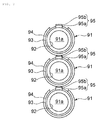
- FIG. 6 is a perspective view illustrating a fuel cell as a fourth embodiment of the present invention
- FIG. 7 is a schematic front view illustrating a fuel cell stack obtained by stacking a plurality of fuel cells according to this embodiment.
- a fuel cell 91 shown in FIG. 6 is a fuel cell referred to as a so-called cylindrical SOFC.
- a flow path 91a for the passage of a fuel gas is provided in the center of the cylindrical body.
- a cylindrical air electrode 92 is provided to surround the flow path 91a.
- a cylindrical solid oxide electrolyte layer 93 is provided outside the air electrode 92, and a fuel electrode 94 is provided further outside.
- the fuel electrode 94 has the shape of a cylinder with a portion removed therefrom, and the region of the fuel electrode 94 with the portion removed therefrom is provided with an interconnector 95.
- This interconnector 95 has a ceramic layer 95a, and a high-thermal-expansion-coefficient material layer 95b laminated on one side of the ceramic layer 95a. More specifically, the interconnector 95 is composed of a ceramic substrate for an electrochemical element according to the present invention.
- the ceramic substrate for an electrochemical element according to the present invention can be also used for the cylindrical fuel cell 91.
- adjacent fuel cells 91 are stacked one another with such interconnectors 95 interposed therebetween.
- interconnectors 95 have portions, not shown, provided with electrically conductive paths such as via hole conductors, in order to electrically connect the adjacent fuel cells 91 to each other.
- the fuel cell as an embodiment of the present invention is not limited to plate-like laminated and cylindrical forms as described above, but may be, for example, a fuel cell in the form referred to as a flat tube.
- the ceramic substrate for an electrochemical element according to the present invention is used for the separator in fuel cell or fuel cell stack, or the interconnector in the embodiments described above, the ceramic substrate for an electrochemical element according to the present invention can be used as a ceramic material for not only the solid oxide fuel cells, but also various fuel cells, or various electrode chemical elements other batteries such as electric double layer capacitors.
- a yttrium oxide powder and a zirconia power were weighed, and mixed with a resin binder and a solvent to obtain ceramic slurry.
- This ceramic slurry was subjected to sheet forming to obtain ceramic green sheets.
- the ceramic green sheets were laminated more than once so that the thickness after firing was 500 ⁇ m.
- the laminated body thus obtained was cut so that the planar shape was a square of 5 cm ⁇ 5 cm.
- the laminated body thus obtained was subjected to firing for 2 hours at a temperature of 1300°C to obtain a separator according to a comparative example.
- a green sheet for a high-thermal-expansion-coefficient material layer with its composition shown in Table 1 below was laminated on the front and back surfaces of the laminated body.
- This green sheet for a high-thermal-expansion-coefficient material layer was obtained in a way that various types of oxide powders were weighed so as to provide the composition shown in Table 1 below, and mixed with a carbon powder, a resin binder, and a solvent, and the obtained slurry was subjected to sheet forming.
- the carbon powder was blended so that the porosity of the fired high-thermal-expansion-coefficient material layer was 20 to 30%.
- the green sheet for a high-thermal expansion-coefficient material layer was cut so that the size after firing was a square of 4.5 cm ⁇ 4.5 cm in planar shape.
- the cut green sheet for a high-thermal-expansion-coefficient material layer was subjected to pressure bonding for 2 minutes at a temperature of 80°C onto the laminated body. Then, the laminated body with the green sheet thereon was subjected to firing by keeping the body at a temperature of 1300°C for 2 hours.
- the separator cracked or broken, or warped was rejected.
- the separators which were not found to be cracked, broken, or warped are listed with a symbol of ⁇ in Table 1 below.
- LSCF La 0.8 -Sr 0.2 -C 0.2 -Fe 0.803
- the separators according to Examples 2 to 4 and Comparative Example, prepared in Experimental Example 1, were used to prepare fuel stacks. More specifically, five cells of fuel cells as shown in FIG. 1 were stacked to obtain a fuel cell stack. In this regard, each fuel cell of the fuel cells was used as follows.
- the relationship between the maximum internal temperature difference ⁇ T and cracking was evaluated while measuring the internal temperature of the fuel cell stack obtained in the way mentioned above. More specifically, electric current was applied to the air electrode and fuel electrode of the fuel cell stack to increase the internal temperature. In the case of the cell of the fuel cell in a planar view, the temperatures of nine regions located in a matrix were each measured. Then, among the temperatures at the nine points, the difference in temperature between the two regions with the largest temperature difference was regarded as the maximum temperature difference ⁇ T. Then, the current density was increased, and the current density and the maximum temperature difference ⁇ T were obtained when the cell of the fuel cell was cracked, and regarded as a limited current density and a limit ⁇ T.
Landscapes
- Chemical & Material Sciences (AREA)
- Engineering & Computer Science (AREA)
- Ceramic Engineering (AREA)
- Life Sciences & Earth Sciences (AREA)
- Manufacturing & Machinery (AREA)
- Sustainable Development (AREA)
- Sustainable Energy (AREA)
- Chemical Kinetics & Catalysis (AREA)
- Electrochemistry (AREA)
- General Chemical & Material Sciences (AREA)
- Composite Materials (AREA)
- Fuel Cell (AREA)
- Materials Engineering (AREA)
Applications Claiming Priority (2)
| Application Number | Priority Date | Filing Date | Title |
|---|---|---|---|
| JP2013171371 | 2013-08-21 | ||
| PCT/JP2014/068778 WO2015025642A1 (fr) | 2013-08-21 | 2014-07-15 | Substrat céramique pour un élément électrochimique, procédé permettant de fabriquer ce dernier, pile à combustible, et empilement de piles à combustible |
Publications (2)
| Publication Number | Publication Date |
|---|---|
| EP3038197A1 true EP3038197A1 (fr) | 2016-06-29 |
| EP3038197A4 EP3038197A4 (fr) | 2017-04-12 |
Family
ID=52483424
Family Applications (1)
| Application Number | Title | Priority Date | Filing Date |
|---|---|---|---|
| EP14837601.5A Withdrawn EP3038197A4 (fr) | 2013-08-21 | 2014-07-15 | Substrat céramique pour un élément électrochimique, procédé permettant de fabriquer ce dernier, pile à combustible, et empilement de piles à combustible |
Country Status (4)
| Country | Link |
|---|---|
| US (1) | US9722259B2 (fr) |
| EP (1) | EP3038197A4 (fr) |
| JP (1) | JP6044717B2 (fr) |
| WO (1) | WO2015025642A1 (fr) |
Families Citing this family (4)
| Publication number | Priority date | Publication date | Assignee | Title |
|---|---|---|---|---|
| EP3089252A4 (fr) * | 2013-12-27 | 2017-05-17 | Murata Manufacturing Co., Ltd. | Séparateur pour piles à combustible à électrolyte solide et pile à combustible à électrolyte solide |
| CN108321343A (zh) * | 2017-02-22 | 2018-07-24 | 深圳市格瑞普电池有限公司 | 锂离子电池及其隔膜 |
| EP3664202B1 (fr) | 2017-08-01 | 2023-06-28 | Nissan Motor Co., Ltd. | Unité de cellule |
| JP7537500B2 (ja) * | 2020-08-12 | 2024-08-21 | 株式会社村田製作所 | 多端子積層コンデンサ |
Family Cites Families (17)
| Publication number | Priority date | Publication date | Assignee | Title |
|---|---|---|---|---|
| US4656071A (en) * | 1984-10-29 | 1987-04-07 | Ceramatec, Inc. | Ceramic bodies having a plurality of stress zones |
| JPS63109050A (ja) * | 1986-10-28 | 1988-05-13 | 太陽誘電株式会社 | セラミツク基板 |
| JPH0668885A (ja) * | 1992-08-21 | 1994-03-11 | Ishikawajima Harima Heavy Ind Co Ltd | 固体電解質型燃料電池の製作方法 |
| JP3677386B2 (ja) * | 1998-03-26 | 2005-07-27 | 京セラ株式会社 | 固体電解質型燃料電池セル |
| JP4252453B2 (ja) * | 2001-09-26 | 2009-04-08 | 日本碍子株式会社 | 電気化学セルおよびその製造方法 |
| JP4146738B2 (ja) * | 2002-02-07 | 2008-09-10 | 京セラ株式会社 | 燃料電池セル及びセルスタック並びに燃料電池 |
| KR101136191B1 (ko) * | 2003-09-10 | 2012-04-17 | 트르스티스 오브 보스톤 유니버시티 | 고체 산화물 연료전지 제조 방법 |
| JP5077238B2 (ja) | 2006-10-05 | 2012-11-21 | 株式会社村田製作所 | 固体電解質形燃料電池支持構造体とそれを備えた固体電解質形燃料電池モジュール |
| DE102007022093A1 (de) * | 2007-05-11 | 2008-11-13 | Epcos Ag | Piezoelektrisches Vielschichtbauelement |
| EP2229702B1 (fr) * | 2007-12-21 | 2012-03-28 | Saint-Gobain Ceramics & Plastics, Inc. | Interconnexion céramique pour empilages de piles à combustible |
| WO2009119771A1 (fr) | 2008-03-26 | 2009-10-01 | 財団法人ファインセラミックスセンター | Structure d'empilement pour empilement de piles à combustible à oxyde solide, empilement de piles à combustible à oxyde solide et leur procédé de fabrication |
| JP2009295497A (ja) * | 2008-06-06 | 2009-12-17 | Kansai Electric Power Co Inc:The | 複合基板、複合基板の製造方法、固体酸化物形燃料電池セル、固体酸化物形燃料電池および固体酸化物形燃料電池の製造方法 |
| US20130108943A1 (en) * | 2010-05-04 | 2013-05-02 | Jean Yamanis | Two-layer coatings on metal substrates and dense electrolyte for high specific power metal-supported sofc |
| EP2690694B1 (fr) * | 2011-03-25 | 2016-11-09 | Murata Manufacturing Co., Ltd. | Pile à combustible |
| JP5773341B2 (ja) | 2011-03-25 | 2015-09-02 | 国立研究開発法人物質・材料研究機構 | 無機化合物粒子およびその製造方法 |
| JP5679060B2 (ja) * | 2011-07-21 | 2015-03-04 | 株式会社村田製作所 | 固体酸化物形燃料電池用電気的接続材、固体酸化物形燃料電池、固体酸化物形燃料電池モジュール及び固体酸化物形燃料電池の製造方法 |
| US8921007B2 (en) * | 2011-11-15 | 2014-12-30 | Saint-Gobain Ceramics & Plastics, Inc. | Solid oxide fuel cell interconnect cells |
-
2014
- 2014-07-15 WO PCT/JP2014/068778 patent/WO2015025642A1/fr not_active Ceased
- 2014-07-15 JP JP2015532763A patent/JP6044717B2/ja not_active Expired - Fee Related
- 2014-07-15 EP EP14837601.5A patent/EP3038197A4/fr not_active Withdrawn
-
2016
- 2016-01-08 US US14/991,109 patent/US9722259B2/en not_active Expired - Fee Related
Also Published As
| Publication number | Publication date |
|---|---|
| EP3038197A4 (fr) | 2017-04-12 |
| US9722259B2 (en) | 2017-08-01 |
| WO2015025642A1 (fr) | 2015-02-26 |
| JP6044717B2 (ja) | 2016-12-14 |
| US20160126564A1 (en) | 2016-05-05 |
| JPWO2015025642A1 (ja) | 2017-03-02 |
Similar Documents
| Publication | Publication Date | Title |
|---|---|---|
| JP4950334B2 (ja) | 積層型固体酸化物形燃料電池用スタック構造体、積層型固体酸化物形燃料電池及びその製造方法 | |
| EP1919021B1 (fr) | Élément de plaque mince pour pile d'unité de pile à combustible d'oxyde solide | |
| EP2495791B1 (fr) | Pile à combustible, empilement de piles à combustible, module de piles à combustible et dispositif de piles à combustible | |
| KR101869305B1 (ko) | 셀, 셀 스택 장치, 모듈 및 모듈 수납 장치 | |
| KR101848337B1 (ko) | 셀, 셀 스택 장치, 모듈 및 모듈 수용 장치 | |
| EP3051617A1 (fr) | Empilement de piles à oxyde solide et son procédé de fabrication | |
| US9722259B2 (en) | Ceramic substrate for electrochemical element, manufacturing method therefore, fuel cell, and fuel cell stack | |
| JP5077238B2 (ja) | 固体電解質形燃料電池支持構造体とそれを備えた固体電解質形燃料電池モジュール | |
| CN107710488A (zh) | 燃料电池堆 | |
| JPWO2009001739A1 (ja) | 高温構造材料と固体電解質形燃料電池用セパレータ | |
| US20130071770A1 (en) | High-temperature structural material, structural body for solid electrolyte fuel cell, and solid electrolyte fuel cell | |
| WO2014021446A1 (fr) | Pile à combustible | |
| EP2693545B1 (fr) | Pile à combustible | |
| EP3422448B1 (fr) | Unité de production d'énergie à pile à combustible et empilement de pile à combustible | |
| CN111244498B (zh) | 燃料电池和燃料电池堆 | |
| EP3152794A1 (fr) | Pile à combustible ayant une anode tubulaire plate | |
| JP6748518B2 (ja) | 電気化学反応セルの製造方法 | |
| WO2013062023A1 (fr) | Comprimé fritté céramique, élément à haute température et élément électrochimique | |
| WO2015045682A1 (fr) | Anode de pile à combustible et pile à combustible | |
| WO2008146927A1 (fr) | Ensemble joint d'électrolyte et d'électrode et son procédé de production | |
| WO2012132893A1 (fr) | Pile à combustible | |
| WO2015037329A1 (fr) | Pile à combustible à électrolyte solide et son procédé de fabrication |
Legal Events
| Date | Code | Title | Description |
|---|---|---|---|
| PUAI | Public reference made under article 153(3) epc to a published international application that has entered the european phase |
Free format text: ORIGINAL CODE: 0009012 |
|
| 17P | Request for examination filed |
Effective date: 20160113 |
|
| AK | Designated contracting states |
Kind code of ref document: A1 Designated state(s): AL AT BE BG CH CY CZ DE DK EE ES FI FR GB GR HR HU IE IS IT LI LT LU LV MC MK MT NL NO PL PT RO RS SE SI SK SM TR |
|
| AX | Request for extension of the european patent |
Extension state: BA ME |
|
| DAX | Request for extension of the european patent (deleted) | ||
| A4 | Supplementary search report drawn up and despatched |
Effective date: 20170315 |
|
| RIC1 | Information provided on ipc code assigned before grant |
Ipc: H01M 8/0228 20160101ALI20170309BHEP Ipc: H01M 2/14 20060101ALN20170309BHEP Ipc: H01M 8/0215 20160101AFI20170309BHEP Ipc: C04B 41/50 20060101ALI20170309BHEP Ipc: H01M 8/124 20160101ALN20170309BHEP Ipc: H01M 8/0217 20160101ALN20170309BHEP Ipc: H01M 2/16 20060101ALN20170309BHEP Ipc: B32B 18/00 20060101ALI20170309BHEP |
|
| 17Q | First examination report despatched |
Effective date: 20190507 |
|
| STAA | Information on the status of an ep patent application or granted ep patent |
Free format text: STATUS: THE APPLICATION IS DEEMED TO BE WITHDRAWN |
|
| 18D | Application deemed to be withdrawn |
Effective date: 20190918 |