EP3038882B1 - Befestigungsvorrichtung mit zwei betriebsmodi und kraftfahrzeug mit solch einer vorrichtung - Google Patents
Befestigungsvorrichtung mit zwei betriebsmodi und kraftfahrzeug mit solch einer vorrichtung Download PDFInfo
- Publication number
- EP3038882B1 EP3038882B1 EP14747071.0A EP14747071A EP3038882B1 EP 3038882 B1 EP3038882 B1 EP 3038882B1 EP 14747071 A EP14747071 A EP 14747071A EP 3038882 B1 EP3038882 B1 EP 3038882B1
- Authority
- EP
- European Patent Office
- Prior art keywords
- nut
- window
- wing
- plate
- opening
- Prior art date
- Legal status (The legal status is an assumption and is not a legal conclusion. Google has not performed a legal analysis and makes no representation as to the accuracy of the status listed.)
- Not-in-force
Links
- 238000000605 extraction Methods 0.000 claims description 3
- 230000003100 immobilizing effect Effects 0.000 claims 4
- BASFCYQUMIYNBI-UHFFFAOYSA-N platinum Chemical compound [Pt] BASFCYQUMIYNBI-UHFFFAOYSA-N 0.000 description 7
- 238000001962 electrophoresis Methods 0.000 description 5
- 230000003287 optical effect Effects 0.000 description 5
- 230000002787 reinforcement Effects 0.000 description 5
- 238000012423 maintenance Methods 0.000 description 4
- 239000006185 dispersion Substances 0.000 description 3
- 238000006073 displacement reaction Methods 0.000 description 3
- 208000031968 Cadaver Diseases 0.000 description 2
- 241000920340 Pion Species 0.000 description 2
- 238000001816 cooling Methods 0.000 description 2
- 230000035939 shock Effects 0.000 description 2
- 241001080024 Telles Species 0.000 description 1
- 230000007547 defect Effects 0.000 description 1
- 229940082150 encore Drugs 0.000 description 1
- 230000010354 integration Effects 0.000 description 1
- 230000000670 limiting effect Effects 0.000 description 1
- 230000036961 partial effect Effects 0.000 description 1
- 230000002093 peripheral effect Effects 0.000 description 1
- 230000002829 reductive effect Effects 0.000 description 1
- 230000000284 resting effect Effects 0.000 description 1
- 230000002441 reversible effect Effects 0.000 description 1
Images


Classifications
-
- B—PERFORMING OPERATIONS; TRANSPORTING
- B62—LAND VEHICLES FOR TRAVELLING OTHERWISE THAN ON RAILS
- B62D—MOTOR VEHICLES; TRAILERS
- B62D29/00—Superstructures, understructures, or sub-units thereof, characterised by the material thereof
- B62D29/04—Superstructures, understructures, or sub-units thereof, characterised by the material thereof predominantly of synthetic material
- B62D29/048—Connections therefor, e.g. joints
-
- B—PERFORMING OPERATIONS; TRANSPORTING
- B62—LAND VEHICLES FOR TRAVELLING OTHERWISE THAN ON RAILS
- B62D—MOTOR VEHICLES; TRAILERS
- B62D25/00—Superstructure or monocoque structure sub-units; Parts or details thereof not otherwise provided for
- B62D25/08—Front or rear portions
- B62D25/16—Mud-guards or wings; Wheel cover panels
- B62D25/163—Mounting devices
-
- F—MECHANICAL ENGINEERING; LIGHTING; HEATING; WEAPONS; BLASTING
- F16—ENGINEERING ELEMENTS AND UNITS; GENERAL MEASURES FOR PRODUCING AND MAINTAINING EFFECTIVE FUNCTIONING OF MACHINES OR INSTALLATIONS; THERMAL INSULATION IN GENERAL
- F16B—DEVICES FOR FASTENING OR SECURING CONSTRUCTIONAL ELEMENTS OR MACHINE PARTS TOGETHER, e.g. NAILS, BOLTS, CIRCLIPS, CLAMPS, CLIPS OR WEDGES; JOINTS OR JOINTING
- F16B37/00—Nuts or like thread-engaging members
- F16B37/04—Devices for fastening nuts to surfaces, e.g. sheets, plates
- F16B37/041—Releasable devices
- F16B37/042—Releasable devices locking by rotation
-
- F—MECHANICAL ENGINEERING; LIGHTING; HEATING; WEAPONS; BLASTING
- F16—ENGINEERING ELEMENTS AND UNITS; GENERAL MEASURES FOR PRODUCING AND MAINTAINING EFFECTIVE FUNCTIONING OF MACHINES OR INSTALLATIONS; THERMAL INSULATION IN GENERAL
- F16B—DEVICES FOR FASTENING OR SECURING CONSTRUCTIONAL ELEMENTS OR MACHINE PARTS TOGETHER, e.g. NAILS, BOLTS, CIRCLIPS, CLAMPS, CLIPS OR WEDGES; JOINTS OR JOINTING
- F16B5/00—Joining sheets or plates, e.g. panels, to one another or to strips or bars parallel to them
- F16B5/02—Joining sheets or plates, e.g. panels, to one another or to strips or bars parallel to them by means of fastening members using screw-thread
- F16B5/0216—Joining sheets or plates, e.g. panels, to one another or to strips or bars parallel to them by means of fastening members using screw-thread the position of the plates to be connected being adjustable
- F16B5/0225—Joining sheets or plates, e.g. panels, to one another or to strips or bars parallel to them by means of fastening members using screw-thread the position of the plates to be connected being adjustable allowing for adjustment parallel to the plane of the plates
Definitions
- the present invention relates to a fastening device. It relates more particularly to a device for fixing two elements, adapted to ensure in a first configuration premaintening allowing relative sliding between the two elements, and in a second configuration a complete fixation of the two elements.
- the invention also relates to a motor vehicle provided with such a fixing device.
- a plastic front wing can be mounted on the vehicle structure prior to its passage in cataphoresis and in an oven.
- the passage in an oven submits the wing to high temperatures, of the order of 100 ° C to 120 ° C. This temperature causes an expansion / deformation of the plastic wing up to 30 mm in the longitudinal direction of the vehicle.
- the wing is conventionally attached to the vehicle structure in three attachment points: two high and low rear attachment points on a canopy side reinforcement and a front attachment point on the same reinforcement via a wing support.
- the wing has a lateral lug extending in the transverse direction towards the inside of the vehicle.
- the lateral leg is supported vertically on the wing support secured to the vehicle structure.
- the side tab extends in the longitudinal direction of the vehicle and has a light extending in the same direction. This light is traversed by a guide member passing through the light and clipped vertically into an orifice formed on the wing reinforcement.
- the guide member is adjusted in the light so that the front portion of the wing can slide relative to the guide member and the wing support along the longitudinal dimension of the vehicle while providing indexing in the direction cross.
- the complete attachment of the wing to the wing support is achieved by a screw-nut system which is located near the guide member, typically at the rear of the latter.
- the screw passes through the light of the side tab and another hole on the wing support.
- the screw is tightened so as to ensure complete attachment of the wing to the wing support.
- Such a fixing device is bulky since it comprises a guide member and a screw-nut system dissociated and juxtaposed in the longitudinal direction of the vehicle. In addition, these multiple pieces require as many manipulations and set-up operations.
- the guide member and the screw-nut system are typically located near a fusible rear mounting of the projector.
- the projector comprises in its rear part a fusible fixing lug ensuring the fixation by screw of the projector on the wing support, and its indexing.
- This fusible fastener allows a rupture of the binding in the event of "RCAR" shocks corresponding to shocks with speeds lower than 15km / h (standard meeting the recommendations of insurers aiming at reducing repair costs).
- the indexing along the longitudinal and transverse directions of the rear leg of the headlamp is ensured directly on the wing support by a pin coming from the rear leg which cooperates with a hole or a notch formed on the support of wing.
- the indexing of the projector on the wing support degrades the chain of dimensions and generates geometric dispersions that do not allow to control the clearances and outcrops between the projector and the wing edge, visible from the outside of the vehicle.
- these fixing means and indexing of the rear leg of the projector further encumber the wing attachment area.
- the invention aims to overcome all or part of the above disadvantages by providing a fixing device that overcomes all or part of the above disadvantages in terms of space, a plurality of parts to mount and geometric defects.
- the invention relates to a device for fixing a first plate on a second plate contiguous to one another, one of the plates being provided with a window while the other plate comprises a guide light placed opposite the window, characterized in that it comprises a screw-nut assembly, the screw and the nut being introduced through the window and the light to a position abutment in which a flange adjacent to the screw head is supported on one of the plates, while the nut comprises clipping conformations cooperating in abutment with the other plate to prevent the extraction of the screw assembly.
- the nut comprising a quarter-turn system, movable under the influence of a rotation printed with the screw, between on the one hand an initial angular position in which the nut is introduced into the window and the light, nut having guide flanks fitted with bor ds corresponding the window and the light to wedge the plates relative to each other transversely to the longitudinal direction of the light while allowing a relative sliding between the plates in the longitudinal direction, and secondly a final angular position in which the locking flanks of the nut cooperate abutting against corresponding edges of the window and the light to limit the rotation of the nut, the screw and the nut being thus able to be tightened so as to ensure complete fixation between the two plates via shoulders shaped on the nut, which are offset angularly with respect to the window and the light to cooperate in contact with the adjacent plate.
- the invention also relates to a motor vehicle comprising at least one plastic lateral wing mounted on the vehicle structure, the wing being fixed in its front part to a wing support integral with the vehicle structure, characterized in that it comprises a fixing device according to any one of the preceding claims, the first plate being integral with the wing while the second plate is an integral part of the wing support.
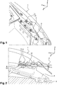
- Figures 1 and 2 a partial view of the left front part of a motor vehicle, illustrating the attachment zone of a front wing 1 and a front left optical projector 2 of the vehicle.
- This vehicle typically comprises a plastic front fender. This is mounted on the structure 3 of the vehicle prior to the passage of the structure in cataphoresis and oven.
- the wing is conventionally fixed to the structure in three attachment points: two high and low rear attachment points and a front attachment point, these points being distributed the mechanical maintenance and isostatism of the wing.
- the front fixing point essentially ensures a fixation in directions Y and Z.
- the structural element of the vehicle on which the wing 1 is fixed is typically an "awning side reinforcement" according to the terminology of the man.
- this attachment to the structure 3 is achieved by means of a wing support 4 which is a stamped piece coming from a shoe fixed or welded to a front spar of the vehicle or to the awning side reinforcement. .
- this support 4 has the general shape of a U tilted at 90 °, one of the branches of the U, located in the upper part, defines a plate on which is fixed a corresponding platen coming from the wing 1.
- first plate 5" and second plate 6 we will designate the plates of the wing and the wing support respectively by the terms “first plate 5" and second plate 6 ".
- the passage in cataphoresis and oven of the wing 1 implies an expansion of the latter which can reach 30 mm in the longitudinal direction X.
- the front part of the wing 1 is fixed to the vehicle structure by means of the fastening device according to the invention, which provides two functions according to the phases of use: in a first phase, the fastening device ensures a premaintening of the wing 1 during the phases of cataphoresis and of passage in an oven, this premaintening allowing a displacement of the front part of the wing 1 in the longitudinal direction X, so as to allow the expansion and retraction of the wing; in a second phase, the fixing device ensures a complete attachment of the wing 1 on the structure, eliminating all possible movements.
- the fixing device of the invention for securing the first plate 5 to the second plate 6 contiguous to each other is defined as follows: the first plate 5 comprises a window 7 ( Figures 3, 4 , 11-13 ).
- the second plate 6 comprises a guide light 8 ( Figures 11-15 ), placed opposite the window 7.
- the window 7 has an elongated shape extending, like the light 8 in the longitudinal direction X of the vehicle.
- the fixing device of the invention comprises a screw-nut assembly consisting of a screw 9 and a nut 10 introduced together through the window 7 and the light 8 to a stop position in which a flange 11 adjacent to the screw head bears on the first plate 5.
- the flange 11 may be directly constituted by the screw head.
- the nut 10 comprises clipping conformations 12, typically two elastically deformable tabs, located on either side of the main body of the nut 10, these fins co-operating in abutment with the second plate 6 in the vicinity of the slot 8, to prevent extraction of the screw-nut assembly.
- the screw 9 is partially screwed onto the nut 10.
- the nut 10 comprises a quarter turn system, movable under the influence of a rotation printed with the screw.
- the rotation is carried out between on the one hand an initial angular position ( figures 5 , 11, 14, 15 ) in which the nut 10 is introduced into the window 7 and the light 8, the nut 10 having guide flanks 13 fitted with corresponding edges of the window 7 and the light 8 to wedge and pre-hold the plates 5, 6 relative to each other in the transverse direction Y, while allowing relative sliding between the plates 5, 6 in the longitudinal direction X, and secondly a final angular position ( figure 13 ) in which locking flanks 14 ( Figures 9, 10 ) of the nut 10 cooperate abutting against corresponding edges of the window 7 and the slot 8 to limit the rotation of the nut 10 to a quarter of a turn.
- an initial angular position figures 5 , 11, 14, 15
- the nut 10 having guide flanks 13 fitted with corresponding edges of the window 7 and the light 8 to wedge and pre-hold the plates 5, 6 relative to each other in the transverse direction Y, while allowing relative sliding between the plates 5, 6 in the longitudinal direction X
- the nut 10 is locked in rotation when the rotation printed on the screw 9 is always in the same direction.
- the rotation of the screw 9 always in the same direction then causes the nut 10 to rise again in order to completely tighten the plates 5, 6.
- the nut 10 therefore comprises shoulders 17 ( Figures 7, 9, 10 ) whose dimensions are adjusted to pass through the window 7 and the light 8 when the screw-nut assembly is in its initial angular configuration ( figure 11 ), but whose shapes come to cooperate in contact with the second plate 6, in the vicinity of the light 8 when the screw-nut assembly is disposed in its final angular position ( figure 13 ).
- the nut 10 consists of a one-piece assembly comprising a main body having in side view the general shape of a T upside down extending in the axial direction of screwing.
- the thickness of the T is slightly less than the transverse dimensions of the window 7 and the 8.
- a clearance of the order of one to two millimeters is formed vis-à-vis the plates 5, 6 so as to pass the nut in the window 7 and the light 8.
- the main body of the nut 10 is decomposed into an upper block 15 and a lower block 16.
- the upper block 15 forms the leg of the T on which are formed the guide flanks 13 and the flanks of blockages 14. These flanks are shaped along cylindrical generatrices parallel to the axial direction of screwing.
- the lower block 16 forms the transverse branch of the T at the ends of which are located the shoulders 17.
- the clipping conformations 12 consisting of elastically deformable tabs extend from opposite faces of the lower block 16 these faces defining between them the thickness of the T.
- the lower block 16 has the general shape of an elongate parallelepiped whose length is slightly less than the length of the window 7. A clearance of the order of 1 to 2 mm is formed between the lower block 16 and the window 7 so as to facilitate its passage through it.
- the clipping conformations 12 are located in the middle of the long sides of the elongated shape of the lower block 16 ( Figures 9, 10 ).
- the lower block 16 has a tapered shape on all four sides from its edge adjacent to the upper block 15 towards its opposite free edge. This aspect is further to facilitate the passage of the lower block 16 in the window and the light.
- the upper block 15 has a general shape inscribed in a square of which two opposite sides partially marry the guide flanks 13 and two other opposite sides partially marry the locking flanks 14.
- the guide flanks 13 and the locking flanks 14 meet in the form of two opposite edges 18 (corresponding to two opposite corners of the square) and two rounded shapes 19, which allow the rotation of a quarter turn of the nut 10 between the initial and final angular positions by sliding along the longitudinal edges of the window 7 and the light 8.
- the nut 10 has a threaded central hole 20 ( Figures 9, 10 ) passing through the upper block 15 and the lower block 16 from one side, substantially in the vertical direction Z when the screw-nut assembly is in place on the vehicle.
- the motor vehicle comprising a fixing device according to the invention allows the improved fixing of an optical projector 2.
- the latter comprises in its rear part a lug 21 provided with a fusible zone 22 in case of impact ( figure 3 ).
- the latter is of conventional design and well known to those skilled in the art (weakened and frangible portion able to yield when a force exceeding a predetermined threshold is applied, here in the longitudinal direction X).
- an indexing pin cooperating directly with an orifice 23 ( figure 4 ) formed in the first plate 5, in the longitudinal extension of the window 5 towards the front of the vehicle.
- the tab 21 is also attached to the wing support 4 via a fastening screw screwed into a corresponding hole 24 ( figure 4 ), which is located between the indexing orifice 23 and the fusibility zone 22.
Landscapes
- Engineering & Computer Science (AREA)
- Mechanical Engineering (AREA)
- General Engineering & Computer Science (AREA)
- Chemical & Material Sciences (AREA)
- Combustion & Propulsion (AREA)
- Transportation (AREA)
- Architecture (AREA)
- Structural Engineering (AREA)
- Lighting Device Outwards From Vehicle And Optical Signal (AREA)
Claims (7)
- Vorrichtung zur Befestigung einer ersten Platte (5) an einer zweiten Platte (6), die aneinanderliegen, wobei eine der Platten mit einem Fenster (7) versehen ist, während die andere Platte einen Führungsschlitz (8) umfasst, der gegenüber dem Fenster (7) angeordnet ist, umfassend eine Schraube-Mutter-Anordnung, wobei die Schraube (9) und die Mutter (10) durch das Fenster (7) und den Schlitz (8) hindurch bis zu einer Anschlagposition eingeführt werden, in der ein an den Schraubenkopf (9) angrenzender Bund (11) auf einer der Platten aufliegt, während die Mutter (10) Clip-Ausbildungen (12) umfasst, die in Anlage mit der anderen Platte zusammenwirken, um das Herausziehen der Schraube-Mutter-Anordnung zu verhindern, wobei die Mutter (10) ein Viertelumdrehungssystem umfasst, das unter dem Einfluss einer der Schraube (9) auferlegten Drehung beweglich ist zwischen einerseits einer Ausgangswinkelposition, in der die Mutter (10) in das Fenster (7) und den Schlitz (8) eingeführt ist, wobei die Mutter (10) Führungsflanken (13) umfasst, die an die korrespondierenden Ränder des Fensters (7) und des Schlitzes (8) angepasst sind, um die Platten (5, 6) quer zur Längsrichtung des Schlitzes (8) gegeneinander zu sichern und gleichzeitig ein relatives Gleiten zwischen den Platten (5, 6) in Längsrichtung zuzulassen, und andererseits einer Endwinkelposition, in der die Hemmflanken (14) der Mutter (10) in Anlage an korrespondierende Ränder des Fensters (7) und des Schlitzes (8) zusammenwirken, um das Drehen der Mutter (10) zu begrenzen, wobei die Schraube (9) und die Mutter (10) dadurch geeignet sind, so festgezogen zu werden, dass eine vollständige Befestigung zwischen den beiden Platten (5, 6) über Schultern (17) gewährleistet ist, die an der Mutter (10) ausgebildet sind, die winklig in Bezug auf das Fenster (7) und den Schlitz (8) versetzt sind, um in Kontakt mit der angrenzenden Platte (6) zusammenzuwirken, dadurch gekennzeichnet, dass die Mutter (10) aus einer Monoblock-Anordnung besteht, die einen Hauptkörper umfasst, der in der Seitenansicht die Grundform eines umgekehrten T hat, das sich entlang der axialen Schraubrichtung erstreckt, wobei die Dicke des T geringer als die Querabmessungen des Fensters (7) und des Schlitzes (8) ist, wobei der Hauptkörper einerseits aus einem oberen Block (15) zusammengesetzt ist, der das Bein des T bildet, an dem die Führungsflanken (13) und die Hemmflanken (14) entlang der zylindrischen Mantellinien parallel zur axialen Schraubrichtung ausgebildet sind, und anderseits aus einem unteren Block (16), der den Querschenkel des T bildet, an dessen Enden die Schultern (17) befindlich sind, und dass der obere Block (15) eine Grundform hat, die in ein Viereck einbeschrieben ist, von dem zwei entgegengesetzte Seiten eng an den Führungsflanken (13) anliegen und die beiden anderen entgegengesetzten Seiten eng an den Hemmflanken (14) anliegen, wobei die Führungsflanken (13) und die Hemmflanken (14) in Form von zwei entgegengesetzten Kanten (18) und von zwei gerundeten Formen (19) zusammentreffen, die das Drehen der Mutter (10) um eine Viertelumdrehung zwischen den Ausgangs- und Endwinkelpositionen zulassen.
- Befestigungsvorrichtung nach Anspruch 1, dadurch gekennzeichnet, dass der untere Block (16) eine spindelartige Form von seinem an den oberen Block (15) angrenzenden Rand bis zu seinem entgegengesetzten freien Rand hat.
- Befestigungsvorrichtung nach Anspruch 2, dadurch gekennzeichnet, dass die Clip-Ausbildungen (12) sich von entgegengesetzten Flächen des unteren Blocks (16) aus erstrecken, wobei diese Flächen untereinander die Dicke des T definieren.
- Kraftfahrzeug mit mindestens einem seitlichen Kotflügel (1) aus Kunststoff, der an der Struktur des Fahrzeugs montiert ist, wobei der Kotflügel (1) in seinem vorderen Teil an einem Kotflügelhalter (4) befestigt ist, der fest mit der Struktur des Fahrzeugs verbunden ist, dadurch gekennzeichnet, dass es eine Befestigungsvorrichtung nach einem der vorhergehenden Ansprüche umfasst, wobei die erste Platte (5) einstückig mit dem Kotflügel (1) ist, während die zweite Platte (6) fester Bestandteil des Kotflügelhalters (4) ist.
- Kraftfahrzeug nach Anspruch 4, dadurch gekennzeichnet, dass das Fenster (7) in der ersten Platte (5) ausgebildet ist, während der Schlitz (8) in der zweiten Platte (6) ausgebildet ist, wobei die Länge des Schlitzes (8) zwischen 40 mm und 60 mm beträgt, wobei die Länge des Fensters (7) zwischen 20 und 30 mm beträgt.
- Kraftfahrzeug nach Anspruch 5, dadurch gekennzeichnet, dass es einen Scheinwerfer (2) umfasst, der in seinem hinteren Teil eine Lasche (21) umfasst, die mit einem Schmelzbarkeitsbereich (22) für den Fall eines Zusammenstoßes versehen ist, hinter dem ein Indexierungszapfen vorgesehen ist, der direkt mit einer Öffnung (23) zusammenwirkt, die in der ersten Platte (5) ausgebildet ist, wobei die Lasche (21) am Kotflügelhalter (4) über eine Befestigungsschraube befestigt ist, die zwischen dem Indexierungszapfen und dem Schmelzbarkeitsbereich(22) befindlich ist.
- Kraftfahrzeug nach einem der Ansprüche 4 bis 6, dadurch gekennzeichnet, dass sich die erste Platte (5) und die zweite (6) Platte quer zur Längsrichtung (X) vom Kotflügel (1) und der Struktur des Fahrzeugs aus zum Inneren des Fahrzeugs hin erstrecken, wobei das Fenster (7) und der Schlitz (8) sich im Wesentlichen parallel zur Längsrichtung (X) des Fahrzeugs erstrecken.
Applications Claiming Priority (2)
| Application Number | Priority Date | Filing Date | Title |
|---|---|---|---|
| FR1358299A FR3010036B1 (fr) | 2013-08-30 | 2013-08-30 | Dispositif de fixation a deux modes d'utilisation et vehicule automobile comprenant un tel dispositif |
| PCT/FR2014/051669 WO2015028729A1 (fr) | 2013-08-30 | 2014-06-30 | Dispositif de fixation à deux modes d'utilisation et véhicule automobile comprenant un tel dispositif |
Publications (2)
| Publication Number | Publication Date |
|---|---|
| EP3038882A1 EP3038882A1 (de) | 2016-07-06 |
| EP3038882B1 true EP3038882B1 (de) | 2018-02-14 |
Family
ID=49876787
Family Applications (1)
| Application Number | Title | Priority Date | Filing Date |
|---|---|---|---|
| EP14747071.0A Not-in-force EP3038882B1 (de) | 2013-08-30 | 2014-06-30 | Befestigungsvorrichtung mit zwei betriebsmodi und kraftfahrzeug mit solch einer vorrichtung |
Country Status (3)
| Country | Link |
|---|---|
| EP (1) | EP3038882B1 (de) |
| FR (1) | FR3010036B1 (de) |
| WO (1) | WO2015028729A1 (de) |
Families Citing this family (4)
| Publication number | Priority date | Publication date | Assignee | Title |
|---|---|---|---|---|
| CN114132390A (zh) * | 2022-01-11 | 2022-03-04 | 徐州徐工矿业机械有限公司 | 矿用自卸车货厢挡泥板固定装置及矿用自卸车 |
| CN117346113A (zh) * | 2023-11-13 | 2024-01-05 | 中国港湾工程有限责任公司 | 钢结构上灯具的固定装置 |
| WO2025111637A1 (en) * | 2023-11-28 | 2025-06-05 | Trelleborg Perth Pty Ltd | A fastener with a locking nut |
| CN119389330A (zh) * | 2024-11-27 | 2025-02-07 | 宜宾凯翼汽车有限公司 | 一种用于汽车翼子板安装的辅助装置 |
Family Cites Families (3)
| Publication number | Priority date | Publication date | Assignee | Title |
|---|---|---|---|---|
| US5028190A (en) * | 1990-09-17 | 1991-07-02 | Chrysler Corporation | Snap-in floating screw-anchor |
| DE19809935C2 (de) * | 1998-03-07 | 2002-11-28 | Rehau Ag & Co | Verfahren zum Verbinden eines Stoßfängers |
| FR2947314B1 (fr) * | 2009-06-26 | 2011-06-17 | Raymond A & Cie | Dispositif de fixation a ecrou plastique |
-
2013
- 2013-08-30 FR FR1358299A patent/FR3010036B1/fr not_active Expired - Fee Related
-
2014
- 2014-06-30 EP EP14747071.0A patent/EP3038882B1/de not_active Not-in-force
- 2014-06-30 WO PCT/FR2014/051669 patent/WO2015028729A1/fr not_active Ceased
Also Published As
| Publication number | Publication date |
|---|---|
| WO2015028729A1 (fr) | 2015-03-05 |
| EP3038882A1 (de) | 2016-07-06 |
| FR3010036B1 (fr) | 2017-01-13 |
| FR3010036A1 (fr) | 2015-03-06 |
Similar Documents
| Publication | Publication Date | Title |
|---|---|---|
| EP3765337B1 (de) | Vorrichtung zur befestigung eines sensors an einem fahrzeug sowie montageverfahren | |
| EP1604886B1 (de) | Kraftfahrzeugrahmenanordnung | |
| EP2914476B1 (de) | Vorrichtung zur befestigung zweier bauteile aneinander mit einem gleitenden positionierungselement | |
| WO2015028729A1 (fr) | Dispositif de fixation à deux modes d'utilisation et véhicule automobile comprenant un tel dispositif | |
| EP3331726B1 (de) | Kraftfahrzeug mit einem scheinwerfer und einer mit einem unteren verankerungselement aufweisenden signalleuchte | |
| EP2655167B1 (de) | Vorrichtung zur verstärkung des flügels eines fahrzeugs auf einer karosserie | |
| EP3380366B1 (de) | Vorrichtung zur montage eines radars für ein kraftfahrzeug | |
| FR2924085A1 (fr) | Dispositif et procede de fixation d'un ensemble d'aile sur une paroi de caisse d'un vehicule automobile | |
| FR3038289A1 (fr) | Projecteur avant de vehicule automobile muni d’un boitier comportant un element d’ancrage inferieur | |
| EP3381747A1 (de) | Befestigungselement eines scheinwerfers eines fahrzeugs | |
| EP1574422B1 (de) | Querträger eines Fahrzeugs und Fahrzeug mit einem solchen Querträger | |
| EP3409567B1 (de) | Haltevorrichtung für armaturenbrett eines kraftfahrzeugs | |
| FR2991962A1 (fr) | Dispositif pour regler la position d'un module de porte sur la doublure d'une porte de vehicule automobile | |
| EP0459849B1 (de) | Einstellbare Befestigungsvorrichtung für eine Fahrzeugstossstange | |
| FR3070147B1 (fr) | Dispositif de fixation d’un equipement sur un chassis de vehicule automobile ayant une cinematique de choc en rotation | |
| FR3029162A1 (fr) | Agencement pour vehicule automobile muni d'une entretoise ajustable disposee entre deux elements de structure | |
| EP1934081B1 (de) | Abdeckung für eine lenksäule | |
| EP2045171B1 (de) | Frontmodul für Kraftfahrzeuge und Montageverfahren dafür | |
| FR3110509A1 (fr) | Châssis d'un véhicule automobile équipé d'un avertisseur sonore fixé à un support monté sur le châssis basculant à un seuil d'effort prédéfini. | |
| FR2931408A1 (fr) | Systeme de fixation d'un feu de signalisation dans un logement de la carrosserie d'un vehicule automobile | |
| FR3007379A1 (fr) | Dispositif pour la fixation d'un element rapporte sur la carrosserie d'un vehicule | |
| FR2758509A1 (fr) | Dispositif de fixation d'un pare-chocs sur la caisse d'un vehicule automobile | |
| FR3167904A1 (fr) | Système de guidage d’un projecteur par rapport à une caisse d’un véhicule, durant un choc à l’avant dudit véhicule | |
| EP2139725B1 (de) | Verkleidungstafelanordnung für automobiltüren | |
| FR3012775A1 (fr) | Agencement interieur d'un vehicule automobile comportant un module de rangement amovible |
Legal Events
| Date | Code | Title | Description |
|---|---|---|---|
| PUAI | Public reference made under article 153(3) epc to a published international application that has entered the european phase |
Free format text: ORIGINAL CODE: 0009012 |
|
| 17P | Request for examination filed |
Effective date: 20160215 |
|
| AK | Designated contracting states |
Kind code of ref document: A1 Designated state(s): AL AT BE BG CH CY CZ DE DK EE ES FI FR GB GR HR HU IE IS IT LI LT LU LV MC MK MT NL NO PL PT RO RS SE SI SK SM TR |
|
| AX | Request for extension of the european patent |
Extension state: BA ME |
|
| DAX | Request for extension of the european patent (deleted) | ||
| GRAP | Despatch of communication of intention to grant a patent |
Free format text: ORIGINAL CODE: EPIDOSNIGR1 |
|
| INTG | Intention to grant announced |
Effective date: 20170825 |
|
| GRAS | Grant fee paid |
Free format text: ORIGINAL CODE: EPIDOSNIGR3 |
|
| GRAA | (expected) grant |
Free format text: ORIGINAL CODE: 0009210 |
|
| AK | Designated contracting states |
Kind code of ref document: B1 Designated state(s): AL AT BE BG CH CY CZ DE DK EE ES FI FR GB GR HR HU IE IS IT LI LT LU LV MC MK MT NL NO PL PT RO RS SE SI SK SM TR |
|
| REG | Reference to a national code |
Ref country code: GB Ref legal event code: FG4D Free format text: NOT ENGLISH |
|
| REG | Reference to a national code |
Ref country code: CH Ref legal event code: EP |
|
| REG | Reference to a national code |
Ref country code: IE Ref legal event code: FG4D Free format text: LANGUAGE OF EP DOCUMENT: FRENCH |
|
| REG | Reference to a national code |
Ref country code: DE Ref legal event code: R096 Ref document number: 602014020958 Country of ref document: DE Ref country code: AT Ref legal event code: REF Ref document number: 969661 Country of ref document: AT Kind code of ref document: T Effective date: 20180315 |
|
| REG | Reference to a national code |
Ref country code: NL Ref legal event code: MP Effective date: 20180214 Ref country code: FR Ref legal event code: PLFP Year of fee payment: 5 |
|
| REG | Reference to a national code |
Ref country code: AT Ref legal event code: MK05 Ref document number: 969661 Country of ref document: AT Kind code of ref document: T Effective date: 20180214 |
|
| PG25 | Lapsed in a contracting state [announced via postgrant information from national office to epo] |
Ref country code: NO Free format text: LAPSE BECAUSE OF FAILURE TO SUBMIT A TRANSLATION OF THE DESCRIPTION OR TO PAY THE FEE WITHIN THE PRESCRIBED TIME-LIMIT Effective date: 20180514 Ref country code: FI Free format text: LAPSE BECAUSE OF FAILURE TO SUBMIT A TRANSLATION OF THE DESCRIPTION OR TO PAY THE FEE WITHIN THE PRESCRIBED TIME-LIMIT Effective date: 20180214 Ref country code: CY Free format text: LAPSE BECAUSE OF FAILURE TO SUBMIT A TRANSLATION OF THE DESCRIPTION OR TO PAY THE FEE WITHIN THE PRESCRIBED TIME-LIMIT Effective date: 20180214 Ref country code: LT Free format text: LAPSE BECAUSE OF FAILURE TO SUBMIT A TRANSLATION OF THE DESCRIPTION OR TO PAY THE FEE WITHIN THE PRESCRIBED TIME-LIMIT Effective date: 20180214 Ref country code: HR Free format text: LAPSE BECAUSE OF FAILURE TO SUBMIT A TRANSLATION OF THE DESCRIPTION OR TO PAY THE FEE WITHIN THE PRESCRIBED TIME-LIMIT Effective date: 20180214 Ref country code: ES Free format text: LAPSE BECAUSE OF FAILURE TO SUBMIT A TRANSLATION OF THE DESCRIPTION OR TO PAY THE FEE WITHIN THE PRESCRIBED TIME-LIMIT Effective date: 20180214 Ref country code: NL Free format text: LAPSE BECAUSE OF FAILURE TO SUBMIT A TRANSLATION OF THE DESCRIPTION OR TO PAY THE FEE WITHIN THE PRESCRIBED TIME-LIMIT Effective date: 20180214 |
|
| PG25 | Lapsed in a contracting state [announced via postgrant information from national office to epo] |
Ref country code: GR Free format text: LAPSE BECAUSE OF FAILURE TO SUBMIT A TRANSLATION OF THE DESCRIPTION OR TO PAY THE FEE WITHIN THE PRESCRIBED TIME-LIMIT Effective date: 20180515 Ref country code: LV Free format text: LAPSE BECAUSE OF FAILURE TO SUBMIT A TRANSLATION OF THE DESCRIPTION OR TO PAY THE FEE WITHIN THE PRESCRIBED TIME-LIMIT Effective date: 20180214 Ref country code: BG Free format text: LAPSE BECAUSE OF FAILURE TO SUBMIT A TRANSLATION OF THE DESCRIPTION OR TO PAY THE FEE WITHIN THE PRESCRIBED TIME-LIMIT Effective date: 20180514 Ref country code: SE Free format text: LAPSE BECAUSE OF FAILURE TO SUBMIT A TRANSLATION OF THE DESCRIPTION OR TO PAY THE FEE WITHIN THE PRESCRIBED TIME-LIMIT Effective date: 20180214 Ref country code: RS Free format text: LAPSE BECAUSE OF FAILURE TO SUBMIT A TRANSLATION OF THE DESCRIPTION OR TO PAY THE FEE WITHIN THE PRESCRIBED TIME-LIMIT Effective date: 20180214 Ref country code: AT Free format text: LAPSE BECAUSE OF FAILURE TO SUBMIT A TRANSLATION OF THE DESCRIPTION OR TO PAY THE FEE WITHIN THE PRESCRIBED TIME-LIMIT Effective date: 20180214 |
|
| PG25 | Lapsed in a contracting state [announced via postgrant information from national office to epo] |
Ref country code: MT Free format text: LAPSE BECAUSE OF FAILURE TO SUBMIT A TRANSLATION OF THE DESCRIPTION OR TO PAY THE FEE WITHIN THE PRESCRIBED TIME-LIMIT Effective date: 20180214 |
|
| PG25 | Lapsed in a contracting state [announced via postgrant information from national office to epo] |
Ref country code: RO Free format text: LAPSE BECAUSE OF FAILURE TO SUBMIT A TRANSLATION OF THE DESCRIPTION OR TO PAY THE FEE WITHIN THE PRESCRIBED TIME-LIMIT Effective date: 20180214 Ref country code: IT Free format text: LAPSE BECAUSE OF FAILURE TO SUBMIT A TRANSLATION OF THE DESCRIPTION OR TO PAY THE FEE WITHIN THE PRESCRIBED TIME-LIMIT Effective date: 20180214 Ref country code: EE Free format text: LAPSE BECAUSE OF FAILURE TO SUBMIT A TRANSLATION OF THE DESCRIPTION OR TO PAY THE FEE WITHIN THE PRESCRIBED TIME-LIMIT Effective date: 20180214 Ref country code: AL Free format text: LAPSE BECAUSE OF FAILURE TO SUBMIT A TRANSLATION OF THE DESCRIPTION OR TO PAY THE FEE WITHIN THE PRESCRIBED TIME-LIMIT Effective date: 20180214 Ref country code: PL Free format text: LAPSE BECAUSE OF FAILURE TO SUBMIT A TRANSLATION OF THE DESCRIPTION OR TO PAY THE FEE WITHIN THE PRESCRIBED TIME-LIMIT Effective date: 20180214 |
|
| REG | Reference to a national code |
Ref country code: DE Ref legal event code: R097 Ref document number: 602014020958 Country of ref document: DE |
|
| PG25 | Lapsed in a contracting state [announced via postgrant information from national office to epo] |
Ref country code: DK Free format text: LAPSE BECAUSE OF FAILURE TO SUBMIT A TRANSLATION OF THE DESCRIPTION OR TO PAY THE FEE WITHIN THE PRESCRIBED TIME-LIMIT Effective date: 20180214 Ref country code: SK Free format text: LAPSE BECAUSE OF FAILURE TO SUBMIT A TRANSLATION OF THE DESCRIPTION OR TO PAY THE FEE WITHIN THE PRESCRIBED TIME-LIMIT Effective date: 20180214 Ref country code: CZ Free format text: LAPSE BECAUSE OF FAILURE TO SUBMIT A TRANSLATION OF THE DESCRIPTION OR TO PAY THE FEE WITHIN THE PRESCRIBED TIME-LIMIT Effective date: 20180214 Ref country code: SM Free format text: LAPSE BECAUSE OF FAILURE TO SUBMIT A TRANSLATION OF THE DESCRIPTION OR TO PAY THE FEE WITHIN THE PRESCRIBED TIME-LIMIT Effective date: 20180214 |
|
| PLBE | No opposition filed within time limit |
Free format text: ORIGINAL CODE: 0009261 |
|
| STAA | Information on the status of an ep patent application or granted ep patent |
Free format text: STATUS: NO OPPOSITION FILED WITHIN TIME LIMIT |
|
| 26N | No opposition filed |
Effective date: 20181115 |
|
| REG | Reference to a national code |
Ref country code: CH Ref legal event code: PL |
|
| GBPC | Gb: european patent ceased through non-payment of renewal fee |
Effective date: 20180630 |
|
| PG25 | Lapsed in a contracting state [announced via postgrant information from national office to epo] |
Ref country code: SI Free format text: LAPSE BECAUSE OF FAILURE TO SUBMIT A TRANSLATION OF THE DESCRIPTION OR TO PAY THE FEE WITHIN THE PRESCRIBED TIME-LIMIT Effective date: 20180214 |
|
| REG | Reference to a national code |
Ref country code: BE Ref legal event code: MM Effective date: 20180630 |
|
| PG25 | Lapsed in a contracting state [announced via postgrant information from national office to epo] |
Ref country code: MC Free format text: LAPSE BECAUSE OF FAILURE TO SUBMIT A TRANSLATION OF THE DESCRIPTION OR TO PAY THE FEE WITHIN THE PRESCRIBED TIME-LIMIT Effective date: 20180214 Ref country code: LU Free format text: LAPSE BECAUSE OF NON-PAYMENT OF DUE FEES Effective date: 20180630 |
|
| REG | Reference to a national code |
Ref country code: IE Ref legal event code: MM4A |
|
| PG25 | Lapsed in a contracting state [announced via postgrant information from national office to epo] |
Ref country code: GB Free format text: LAPSE BECAUSE OF NON-PAYMENT OF DUE FEES Effective date: 20180630 Ref country code: IE Free format text: LAPSE BECAUSE OF NON-PAYMENT OF DUE FEES Effective date: 20180630 Ref country code: LI Free format text: LAPSE BECAUSE OF NON-PAYMENT OF DUE FEES Effective date: 20180630 Ref country code: CH Free format text: LAPSE BECAUSE OF NON-PAYMENT OF DUE FEES Effective date: 20180630 |
|
| PG25 | Lapsed in a contracting state [announced via postgrant information from national office to epo] |
Ref country code: BE Free format text: LAPSE BECAUSE OF NON-PAYMENT OF DUE FEES Effective date: 20180630 |
|
| PG25 | Lapsed in a contracting state [announced via postgrant information from national office to epo] |
Ref country code: TR Free format text: LAPSE BECAUSE OF FAILURE TO SUBMIT A TRANSLATION OF THE DESCRIPTION OR TO PAY THE FEE WITHIN THE PRESCRIBED TIME-LIMIT Effective date: 20180214 |
|
| PG25 | Lapsed in a contracting state [announced via postgrant information from national office to epo] |
Ref country code: PT Free format text: LAPSE BECAUSE OF FAILURE TO SUBMIT A TRANSLATION OF THE DESCRIPTION OR TO PAY THE FEE WITHIN THE PRESCRIBED TIME-LIMIT Effective date: 20180214 |
|
| PG25 | Lapsed in a contracting state [announced via postgrant information from national office to epo] |
Ref country code: HU Free format text: LAPSE BECAUSE OF FAILURE TO SUBMIT A TRANSLATION OF THE DESCRIPTION OR TO PAY THE FEE WITHIN THE PRESCRIBED TIME-LIMIT; INVALID AB INITIO Effective date: 20140630 Ref country code: MK Free format text: LAPSE BECAUSE OF NON-PAYMENT OF DUE FEES Effective date: 20180214 |
|
| PG25 | Lapsed in a contracting state [announced via postgrant information from national office to epo] |
Ref country code: IS Free format text: LAPSE BECAUSE OF FAILURE TO SUBMIT A TRANSLATION OF THE DESCRIPTION OR TO PAY THE FEE WITHIN THE PRESCRIBED TIME-LIMIT Effective date: 20180614 |
|
| P01 | Opt-out of the competence of the unified patent court (upc) registered |
Effective date: 20230608 |
|
| PGFP | Annual fee paid to national office [announced via postgrant information from national office to epo] |
Ref country code: FR Payment date: 20230628 Year of fee payment: 10 Ref country code: DE Payment date: 20230620 Year of fee payment: 10 |
|
| REG | Reference to a national code |
Ref country code: DE Ref legal event code: R119 Ref document number: 602014020958 Country of ref document: DE |
|
| PG25 | Lapsed in a contracting state [announced via postgrant information from national office to epo] |
Ref country code: DE Free format text: LAPSE BECAUSE OF NON-PAYMENT OF DUE FEES Effective date: 20250101 |
|
| PG25 | Lapsed in a contracting state [announced via postgrant information from national office to epo] |
Ref country code: FR Free format text: LAPSE BECAUSE OF NON-PAYMENT OF DUE FEES Effective date: 20240630 |