EP3040509A1 - The pistons device with compressing-expanding chambers - Google Patents
The pistons device with compressing-expanding chambers Download PDFInfo
- Publication number
- EP3040509A1 EP3040509A1 EP15460063.9A EP15460063A EP3040509A1 EP 3040509 A1 EP3040509 A1 EP 3040509A1 EP 15460063 A EP15460063 A EP 15460063A EP 3040509 A1 EP3040509 A1 EP 3040509A1
- Authority
- EP
- European Patent Office
- Prior art keywords
- rocker
- axis
- shaft
- crankshaft
- piston
- Prior art date
- Legal status (The legal status is an assumption and is not a legal conclusion. Google has not performed a legal analysis and makes no representation as to the accuracy of the status listed.)
- Withdrawn
Links
- 239000000446 fuel Substances 0.000 claims abstract description 7
- 230000000284 resting effect Effects 0.000 claims 2
- 238000002485 combustion reaction Methods 0.000 description 8
- 238000010276 construction Methods 0.000 description 4
- 230000006835 compression Effects 0.000 description 2
- 238000007906 compression Methods 0.000 description 2
- 238000000034 method Methods 0.000 description 2
- 230000002349 favourable effect Effects 0.000 description 1
- 239000012634 fragment Substances 0.000 description 1
- 239000007789 gas Substances 0.000 description 1
- 230000003137 locomotive effect Effects 0.000 description 1
- 238000005065 mining Methods 0.000 description 1
- 239000000203 mixture Substances 0.000 description 1
- 238000007493 shaping process Methods 0.000 description 1
Images


Classifications
-
- F—MECHANICAL ENGINEERING; LIGHTING; HEATING; WEAPONS; BLASTING
- F01—MACHINES OR ENGINES IN GENERAL; ENGINE PLANTS IN GENERAL; STEAM ENGINES
- F01B—MACHINES OR ENGINES, IN GENERAL OR OF POSITIVE-DISPLACEMENT TYPE, e.g. STEAM ENGINES
- F01B9/00—Reciprocating-piston machines or engines characterised by connections between pistons and main shafts, not specific to groups F01B1/00 - F01B7/00
- F01B9/02—Reciprocating-piston machines or engines characterised by connections between pistons and main shafts, not specific to groups F01B1/00 - F01B7/00 with crankshaft
-
- F—MECHANICAL ENGINEERING; LIGHTING; HEATING; WEAPONS; BLASTING
- F01—MACHINES OR ENGINES IN GENERAL; ENGINE PLANTS IN GENERAL; STEAM ENGINES
- F01B—MACHINES OR ENGINES, IN GENERAL OR OF POSITIVE-DISPLACEMENT TYPE, e.g. STEAM ENGINES
- F01B5/00—Reciprocating-piston machines or engines with cylinder axes arranged substantially tangentially to a circle centred on main shaft axis
-
- F—MECHANICAL ENGINEERING; LIGHTING; HEATING; WEAPONS; BLASTING
- F02—COMBUSTION ENGINES; HOT-GAS OR COMBUSTION-PRODUCT ENGINE PLANTS
- F02B—INTERNAL-COMBUSTION PISTON ENGINES; COMBUSTION ENGINES IN GENERAL
- F02B75/00—Other engines
- F02B75/32—Engines characterised by connections between pistons and main shafts and not specific to preceding main groups
Definitions
- the invention is a piston device with compressing-expanding chambers, which can be in particular applied as both an internal combustion engine, a compressor or a pump piston crank mechanism with a rocker arm.
- the traditional crankshaft-piston mechanism commonly known and used, particularly in an internal combustion engine, a compressor, a pump, characterizes with reciprocating motion of a piston connected through a connecting rod to the crankshaft. It converts reciprocating motion of a piston to rotary motion of a crankshaft axis.
- the shaft is arranged in the body device perpendicular to the axis of the cylinder, at the open end of the cylinder.
- the piston device with compressing-expanding chambers invention features the following: an alternative crank-piston mechanism with the rocker arms, a connecting rod, a rocker arm, a connecting rod joining the piston with the rocker arm and provided with a cylinder head which closes the cylinder (as typical in the classic reciprocating piston engine), a fuelling system, a crankshaft connected to the piston via the rocker, characterized in that the axis of the crankshaft is located in the space between the rows of cylinders, which are arranged on opposite sides of the axis and the rows of cylinders are outside this space, preferably the axis of the crankshaft is located between the two rows of cylinders in the space around the rows.
- the rocker moves in a reciprocating
- the rows of cylinders preferably are located symmetrically with respect to the axis of the crankshaft.
- the rocker shaft in the first option concerning the rocker shaft fixation, is mounted in a stationary housing as the crankshaft is.
- the rocker shaft is mounted in the housing slidably in the directions perpendicular to its axis.
- the rocker shaft is mounted rotary in the body.
- the rocker shaft is mounted in the housing both slideably and rotary in the directions perpendicular to its axis.
- the shaft axis of the rocker is parallel to the axis of the crankshaft. Cylinder axes are located outside the axis of the crankshaft.
- the rocker shaft has fixed without eccentricity, and in this case, the rocker is multi-armed, preferably has three arms, one of which is connected via a connecting rod to the crankshaft, and the others through connecting rods to the pistons, preferably wherein the length of the arm connected to the piston rod is different to the length of the arm connected to the connecting rod of the crankshaft.
- the rocker shaft has an eccentric axis. It is done by fixing the rocker on an eccentric shaft, wherein the each piston can be joined to the two arms rocker and multi-arms rocker, preferably a three arms rocker is recommended.
- the planes are parallel to each other and placed vertically, one of these planes is the plane in which the axes of the cylinders are situated right in a row, the second of these planes is the plane in which are situated longitudinal axes of the crankshaft and the shaft arm, and a third of those planes is a plane in which the axes of the cylinders are located in the left row.
- the rocker arm cylinder axes lie in planes, preferably parallel to each other, and the shaft the rocker arm for each cylinder bank is in the span from the bottom of the open portions of the cylinders and between the planes which lie lower open portions of the cylinder.
- Device piston chambers compressing-expanding invention having a mechanism crankshaft piston comprising a crankshaft, connecting rod, rocker arm, connecting rod of the piston, the piston cylinder, the piston pin and pin rocker arm and provided with a head closing one hand cylinder and supply system of the fuel and the wherein the mechanism crankshaft, a piston located in the housing and a crankshaft connected to the piston via the rocker, characterized in that the axis of the crankshaft is located in a space located on one side of the cylinder and the cylinder bank is located outside this space, whereas bolt control arm there and moves in the space limited by the plane in which are located the longitudinal axes of the crankshaft and the rocker arm shaft and the plane in which the axes of the cylinders are situated.
- Swing arm moves in a reciprocating.
- the arm is preferably moved in a space between the plane in which the axis of the crankshaft and the axis of the rocker shaft and the plane in which the axis of the row of cylinders.
- the shaft of the rocker is no cam and the rocker arm is mounted to the shaft without the cam or the rocker arm shaft has an eccentric axis, and when the rocker is mounted on an eccentric shaft.
- the rocker shaft mounted in a stationary housing and the shaft axis of the rocker is parallel to the axis of the crankshaft.
- the rocker shaft is mounted in the housing slidably in the directions perpendicular to its axis and the axis of the rocker shaft is parallel to the axis of the crankshaft.
- the rocker shaft is mounted rotatably in the body, and the axis of the rocker shaft is parallel to the axis of the crankshaft.
- the rocker shaft is mounted in the housing slidably in the directions perpendicular to its axis and a pivot axis of the rocker shaft is parallel to the axis of the crankshaft.
- the essence of the invention consists in such a preferred arrangement and combination of the machine with the mechanism crankshaft piston and the rocker as shown cut up device in a plane perpendicular to the axis of the crankshaft and the axis of the arm and in that the shaft of the rocker is slidably and rotatably mounted in the housing.
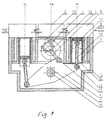
- FIG. 1 shows the device as a two-row internal combustion engine, compressor or pump in the cross section perpendicular to the axis of the crankshaft and the axis of the rocker shaft and the cylinder axis
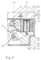
- Figure 2 - fragment of the device of FIG.
- Device piston chambers compressing-expanding invention as an internal combustion engine has a mechanism crankshaft, piston made from the crankshaft 1 of the axis 12 , rod 2 about the axis 15 of the shaft 3 of the arm 4 about the axis 14 , the rocker 4 , the rod 5 of the piston 6 , the piston 6 , cylinder 7 , the head 8 , the pin 11 of the piston 6 , the pin 13 of the arm 4 , located in body 10 .
- the device has a fuel supply system 9.
- the head 8 closes the cylinder 6 above the piston 7 , which is on the opposite side, i.e. the bottom is open.
- the moving reciprocating piston 6 at axis 16 of the cylinder 7 connected via a connecting rod 5 with the rocker 4 mounted on the shaft 3 causes swinging the arm 4 and by connecting the rocker arm 4 via a connecting rod 2 to the crankshaft 1 of the rotation of the crankshaft 1 mounted rotationally in the body 10.
- the crankshaft 1 is connected to the piston 6 via the arm 4 .
- Movement of the reciprocating piston 6 is caused by the pressure of gases produced by combustion of air fuel mixture supplied from a fuel supply system 9 to the cylinder 7 , i.e. as a result of the combustion process in the cylinder space 7 between the upper part of the piston 6 and the lower part of the head 8 .
- the open side i.e.
- the lower part of the cylinder 7 is fastened to the shaft 3 of the arm 4 about an axis 14 parallel to axis 12 of the crank shaft 1 on which is mounted and movable in a plane perpendicular to its axis 14 of the rocker arm 4 .
- the axes 16 of cylinders 7 provided in a cylinder block are preferably located in parallel planes.
- the axes 16 of the cylinder 7 preferably is vertical and the axis 12 of the crankshaft 1 and the axis 14 of the arm 4 in level.
- the axis 12 of the crankshaft 1 is located in the space between the rows of cylinders 7 which are located on opposite sides of the axis 12, preferably symmetrically.
- the rows of cylinders 7 are located outside this space, preferably the axis 12 of the crankshaft: 1 is located between the two rows of cylinders 7 in a space around the rows.
- shaft 3 of the arm 4 is mounted to the stationary body 10 and the axis 14 of the shaft 3 of the arm 4 parallel to the axis 12 of the crankshaft 1 .
- the shaft 3 of the arm 4 is mounted in the housing 10 slidably in the directions perpendicular to its axis 14 and the axis 14 of the shaft 3 of the arm 4 parallel to the axis 12 of the crankshaft 1 .
- the shaft 3 of the arm 4 is mounted rotatably in the body 10 and the axis 14 of the shaft 3 of the arm 4 parallel to the axis 12 of the crankshaft 1 .
- the shaft 3 of the arm 4 is mounted in the housing 10 slidably in the directions perpendicular to its axis 14 and a pivot axis 14 of the shaft 3 of the arm 4 parallel to the axis 12 of the crankshaft 1 .
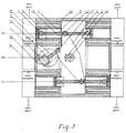
- the shape of the piston 6 in the cylinder 7 situated on the right side of the plane LP is different from the shape of the piston 6 in the cylinder 7 situated on the left side plane LP .
- Axes 16 cylinders 7 are located outside the axis 12 of the crankshaft 1 .
- the arm 4 is preferably moved from the open side of the cylinder 7 between the planes, which are outer side parts of the cylinder 7 .
- the arm 4 is preferably and moves in a space between the plane of the PM , in which the axis 12 of the crankshaft 1 and the axis 14 of the shaft 3 of the arm 4 , and the plane PL of the surface of PP in which the axis 16 of one row of cylinders 7.
- a first embodiment of the shaft 3 of the arm 4 is without a cam 18 and then the rocker arm 4 is mounted on the shaft 3 , without the cam 18 , as shown in Figure 1 .
- the rocker 4 is a multi-armed, preferably has three arms, one of which is connected via a connecting rod 2 of the crankshaft 1 and the other by connecting rods 5 to pistons 6 , wherein preferably the length of the arm connected to the rod 5 of the piston 6 is different as the length of arm connected to the rod 2 of the crankshaft 1 .
- the shaft 3 of the arm 4 has a cam 18 having an axis 19 , and when the rocker arm 4 is mounted on an eccentric shaft 18 3 .
- the rocker 4 is a double arm and each piston 6 is connected via a connecting rod 5 with a rocker arm 4 and the rocker arm 4 of a multi-armed, preferably having three arms.
- the plane PP , PM , PL are parallel to one another and located vertically
- the plane PP is the plane in which are located the axes 16 of the cylinder 7 right row
- the plane LP is the plane in which are located the longitudinal axes of the crankshaft 1 and the shaft 3 of the arm 4
- the plane PL is the plane in which the axes are located 16 cylinders 7 left-hand row.
- the axes 16 of the cylinder 7 lie in planes, preferably parallel to each other, and the shaft 3 of the arm 4 , for each row of cylinders 7 preferably is in the span from the lower open portion of the cylinder 7 and between the planes in which lie the lower open portions of the cylinder 7 .
- the axis 12 of the crankshaft 1 is located in a space located on one side of the cylinder 7 and the cylinder bank 7 located outside this space, while the pin 17 of the rocker arm 4 is located, and moves in the limited plane PM , which are located longitudinal axes of the crankshaft 1 and the shaft 3 of the arm 4 , and the plane P in which are situated the axes 16 of the cylinder 7.
- the rod 2 of the crankshaft 1 pin 17 in the arm 4 is preferably and moves in a space between a plane in which the axis 12 of the crankshaft 1 and the axis 14 of the shaft 3 of the arm 4 , and the plane in which the axis 16 of a row of cylinders 7 .
- the shaft 3 of the arm 4 is without a cam 18 and rocker arm 4 is mounted on the shaft 3 without the eccentric 8 while the second embodiment shown in Figure 5 , the shaft 3 of the arm 4 has a cam 18 of axis 19 and the rocker 4 set 18 is eccentric shaft 3 .
- the arm 4 is mounted to the stationary body 10 and the axis 14 of the shaft 3 of the arm 4 parallel to the axis 12 of the orankshaft 1 .
- the shaft 3 of the arm 4 is mounted in the housing 10 slidably in the directions perpendicular to its axis 14 and the axis 14 of the shaft 3 of the arm 4 parallel to the axis 12 of the crankshaft 1 .
- the shaft 3 of the arm 4 is mounted rotatably in the body 10 and the axis 14 of the shaft 3 of the arm 4 parallel to the axis 12 of the crankshaft 1 .
- the shaft 3 of the arm 4 is mounted in the housing 10 slidably in the directions perpendicular to its axis 14 and a pivot axis 14 of the shaft 3 of the arm 4 parallel to the axis 12 of the crankshaft, 1 .
- the construction of the present invention can then be used in particular to build engines speed to ⁇ 2500 rpm, propelling units with high power, such as ships, locomotives, power generators, large trucks, tractors, construction machinery and mining, etc.
Landscapes
- Engineering & Computer Science (AREA)
- Mechanical Engineering (AREA)
- General Engineering & Computer Science (AREA)
- Chemical & Material Sciences (AREA)
- Combustion & Propulsion (AREA)
- Shafts, Cranks, Connecting Bars, And Related Bearings (AREA)
- Compressors, Vaccum Pumps And Other Relevant Systems (AREA)
- Transmission Devices (AREA)
Applications Claiming Priority (1)
| Application Number | Priority Date | Filing Date | Title |
|---|---|---|---|
| PL409354A PL225176B1 (pl) | 2014-09-02 | 2014-09-02 | Urządzenie tłokowe z komorami sprężająco-rozprężnymi |
Publications (1)
| Publication Number | Publication Date |
|---|---|
| EP3040509A1 true EP3040509A1 (en) | 2016-07-06 |
Family
ID=54072779
Family Applications (1)
| Application Number | Title | Priority Date | Filing Date |
|---|---|---|---|
| EP15460063.9A Withdrawn EP3040509A1 (en) | 2014-09-02 | 2015-09-01 | The pistons device with compressing-expanding chambers |
Country Status (2)
| Country | Link |
|---|---|
| EP (1) | EP3040509A1 (pl) |
| PL (1) | PL225176B1 (pl) |
Citations (10)
| Publication number | Priority date | Publication date | Assignee | Title |
|---|---|---|---|---|
| GB189813703A (en) * | 1898-06-20 | 1899-04-22 | Charles Montague Linley | Improvements in Internal Combustion and other Engines and Compressors. |
| GB190102736A (pl) * | 1901-02-08 | 1902-02-06 | William John Robb | |
| US1033939A (en) * | 1910-04-30 | 1912-07-30 | Banner Motors Ltd | Internal-combustion engine. |
| US1625835A (en) * | 1925-03-14 | 1927-04-26 | O D Sutton | Internal-combustion engine |
| GB354781A (en) * | 1929-06-27 | 1931-08-14 | Ernest Arthur Franks | Improvements in or relating to means for varying the stroke and the compression of an internal combustion engine |
| GB757552A (en) * | 1954-04-15 | 1956-09-19 | English Electric Co Ltd | Improvements in and relating to internal combustion engines |
| DE2237119A1 (de) * | 1972-07-28 | 1974-03-14 | Ernst Beck | Kurbeltrieb |
| US4821695A (en) * | 1986-06-04 | 1989-04-18 | The Trustees Of Columbia University In The City Of New York | Swing beam internal combustion engines |
| WO2002038925A1 (en) * | 2000-11-09 | 2002-05-16 | Nikola Stevanoski | Internal combustion piston engine and oscillator lath |
| DE102004003910A1 (de) * | 2004-01-27 | 2005-08-25 | Adam Opel Ag | Selbstzündende Zweitakt-Brennkraftmaschine mit großem Hub-Bohrungsverhältnis |
-
2014
- 2014-09-02 PL PL409354A patent/PL225176B1/pl unknown
-
2015
- 2015-09-01 EP EP15460063.9A patent/EP3040509A1/en not_active Withdrawn
Patent Citations (10)
| Publication number | Priority date | Publication date | Assignee | Title |
|---|---|---|---|---|
| GB189813703A (en) * | 1898-06-20 | 1899-04-22 | Charles Montague Linley | Improvements in Internal Combustion and other Engines and Compressors. |
| GB190102736A (pl) * | 1901-02-08 | 1902-02-06 | William John Robb | |
| US1033939A (en) * | 1910-04-30 | 1912-07-30 | Banner Motors Ltd | Internal-combustion engine. |
| US1625835A (en) * | 1925-03-14 | 1927-04-26 | O D Sutton | Internal-combustion engine |
| GB354781A (en) * | 1929-06-27 | 1931-08-14 | Ernest Arthur Franks | Improvements in or relating to means for varying the stroke and the compression of an internal combustion engine |
| GB757552A (en) * | 1954-04-15 | 1956-09-19 | English Electric Co Ltd | Improvements in and relating to internal combustion engines |
| DE2237119A1 (de) * | 1972-07-28 | 1974-03-14 | Ernst Beck | Kurbeltrieb |
| US4821695A (en) * | 1986-06-04 | 1989-04-18 | The Trustees Of Columbia University In The City Of New York | Swing beam internal combustion engines |
| WO2002038925A1 (en) * | 2000-11-09 | 2002-05-16 | Nikola Stevanoski | Internal combustion piston engine and oscillator lath |
| DE102004003910A1 (de) * | 2004-01-27 | 2005-08-25 | Adam Opel Ag | Selbstzündende Zweitakt-Brennkraftmaschine mit großem Hub-Bohrungsverhältnis |
Also Published As
| Publication number | Publication date |
|---|---|
| PL409354A1 (pl) | 2016-03-14 |
| PL225176B1 (pl) | 2017-02-28 |
Similar Documents
| Publication | Publication Date | Title |
|---|---|---|
| CN105829678B (zh) | 内燃机 | |
| US20170284291A1 (en) | Independent compression and expansion ratio engine with variable compression ratio | |
| ITMO20010174A1 (it) | Motore a combustione interna a funzionamento alternativo perfezionato | |
| JPH10512937A (ja) | 往復機械 | |
| US4442758A (en) | Piston machine | |
| JP6389250B2 (ja) | 内燃機関 | |
| US3010440A (en) | Internal combustion engine with double acting pistons | |
| EP3040509A1 (en) | The pistons device with compressing-expanding chambers | |
| CN105937442A (zh) | 一种内燃机压缩比调节系统 | |
| US2127758A (en) | Internal combustion engine | |
| US8079341B2 (en) | Piston for an internal combustion engine | |
| US1874195A (en) | Internal combustion engine | |
| US1208854A (en) | Internal-combustion engine. | |
| CN201306211Y (zh) | 双面活塞弧形缸体往复式内燃机 | |
| US1099576A (en) | Valveless internal-combustion motor. | |
| US9638100B2 (en) | Engine | |
| CN111365122A (zh) | 活塞式发动机 | |
| US1946718A (en) | Internal combustion engine | |
| WO2015029093A1 (ja) | 水平対向エンジン | |
| RU2209325C1 (ru) | Двигатель внутреннего сгорания | |
| US12188354B1 (en) | Reciprocating engine with reciprocating rack and pinion | |
| US20080148886A1 (en) | Desmodromic Transmission Engine | |
| KR101382314B1 (ko) | 자동차의 엔진 | |
| RU2182240C2 (ru) | Бесшатунный двигатель внутреннего сгорания | |
| RU2597703C1 (ru) | Кривошипно-шатунный механизм со смещенной шатунной шейкой |
Legal Events
| Date | Code | Title | Description |
|---|---|---|---|
| PUAI | Public reference made under article 153(3) epc to a published international application that has entered the european phase |
Free format text: ORIGINAL CODE: 0009012 |
|
| AK | Designated contracting states |
Kind code of ref document: A1 Designated state(s): AL AT BE BG CH CY CZ DE DK EE ES FI FR GB GR HR HU IE IS IT LI LT LU LV MC MK MT NL NO PL PT RO RS SE SI SK SM TR |
|
| AX | Request for extension of the european patent |
Extension state: BA ME |
|
| STAA | Information on the status of an ep patent application or granted ep patent |
Free format text: STATUS: THE APPLICATION IS DEEMED TO BE WITHDRAWN |
|
| 18D | Application deemed to be withdrawn |
Effective date: 20170110 |