EP3040647A1 - Vorrichtung zur Kühlung eines Hochtemperatursupraleiters - Google Patents
Vorrichtung zur Kühlung eines Hochtemperatursupraleiters Download PDFInfo
- Publication number
- EP3040647A1 EP3040647A1 EP14200513.1A EP14200513A EP3040647A1 EP 3040647 A1 EP3040647 A1 EP 3040647A1 EP 14200513 A EP14200513 A EP 14200513A EP 3040647 A1 EP3040647 A1 EP 3040647A1
- Authority
- EP
- European Patent Office
- Prior art keywords
- heat exchanging
- exchanging medium
- channel
- cryostat
- heat
- Prior art date
- Legal status (The legal status is an assumption and is not a legal conclusion. Google has not performed a legal analysis and makes no representation as to the accuracy of the status listed.)
- Withdrawn
Links
- 238000001816 cooling Methods 0.000 title claims abstract description 35
- 239000002887 superconductor Substances 0.000 title claims abstract description 17
- 238000009413 insulation Methods 0.000 claims abstract description 16
- 239000000725 suspension Substances 0.000 claims abstract description 11
- 239000003949 liquefied natural gas Substances 0.000 claims description 30
- 238000003860 storage Methods 0.000 claims description 20
- 239000007789 gas Substances 0.000 claims description 19
- 229910001220 stainless steel Inorganic materials 0.000 claims description 15
- 239000010935 stainless steel Substances 0.000 claims description 15
- 239000007788 liquid Substances 0.000 claims description 9
- 238000009826 distribution Methods 0.000 claims description 8
- 239000002826 coolant Substances 0.000 claims description 5
- 238000003491 array Methods 0.000 claims description 3
- 239000010410 layer Substances 0.000 description 30
- VNWKTOKETHGBQD-UHFFFAOYSA-N methane Chemical compound C VNWKTOKETHGBQD-UHFFFAOYSA-N 0.000 description 22
- IJGRMHOSHXDMSA-UHFFFAOYSA-N Atomic nitrogen Chemical compound N#N IJGRMHOSHXDMSA-UHFFFAOYSA-N 0.000 description 16
- 230000005611 electricity Effects 0.000 description 13
- 238000000034 method Methods 0.000 description 13
- 230000008569 process Effects 0.000 description 13
- 125000006850 spacer group Chemical group 0.000 description 12
- 239000003345 natural gas Substances 0.000 description 10
- 229910052757 nitrogen Inorganic materials 0.000 description 8
- 230000005855 radiation Effects 0.000 description 6
- 238000005057 refrigeration Methods 0.000 description 6
- 239000007787 solid Substances 0.000 description 6
- 229920003020 cross-linked polyethylene Polymers 0.000 description 5
- 239000004703 cross-linked polyethylene Substances 0.000 description 5
- 238000010586 diagram Methods 0.000 description 5
- 239000000463 material Substances 0.000 description 5
- OKTJSMMVPCPJKN-UHFFFAOYSA-N Carbon Chemical compound [C] OKTJSMMVPCPJKN-UHFFFAOYSA-N 0.000 description 4
- RYGMFSIKBFXOCR-UHFFFAOYSA-N Copper Chemical compound [Cu] RYGMFSIKBFXOCR-UHFFFAOYSA-N 0.000 description 4
- 230000004907 flux Effects 0.000 description 4
- 239000011229 interlayer Substances 0.000 description 4
- 239000000203 mixture Substances 0.000 description 4
- 238000010943 off-gassing Methods 0.000 description 4
- 239000003795 chemical substances by application Substances 0.000 description 3
- 239000010949 copper Substances 0.000 description 3
- 239000000835 fiber Substances 0.000 description 3
- 239000011888 foil Substances 0.000 description 3
- 229910001172 neodymium magnet Inorganic materials 0.000 description 3
- 230000004888 barrier function Effects 0.000 description 2
- 239000004020 conductor Substances 0.000 description 2
- 229910052802 copper Inorganic materials 0.000 description 2
- 239000003365 glass fiber Substances 0.000 description 2
- 238000010438 heat treatment Methods 0.000 description 2
- 229910052734 helium Inorganic materials 0.000 description 2
- 230000004941 influx Effects 0.000 description 2
- 238000005339 levitation Methods 0.000 description 2
- 229910052754 neon Inorganic materials 0.000 description 2
- -1 polyethylene Polymers 0.000 description 2
- 229920006254 polymer film Polymers 0.000 description 2
- 229910052709 silver Inorganic materials 0.000 description 2
- 229920000049 Carbon (fiber) Polymers 0.000 description 1
- 229920000271 Kevlar® Polymers 0.000 description 1
- 239000004677 Nylon Substances 0.000 description 1
- 239000004698 Polyethylene Substances 0.000 description 1
- 239000004642 Polyimide Substances 0.000 description 1
- 241000826860 Trapezium Species 0.000 description 1
- 238000013459 approach Methods 0.000 description 1
- 229910052786 argon Inorganic materials 0.000 description 1
- 230000008859 change Effects 0.000 description 1
- 230000006835 compression Effects 0.000 description 1
- 238000007906 compression Methods 0.000 description 1
- 239000011889 copper foil Substances 0.000 description 1
- 238000013461 design Methods 0.000 description 1
- 238000010292 electrical insulation Methods 0.000 description 1
- 239000011152 fibreglass Substances 0.000 description 1
- 238000002309 gasification Methods 0.000 description 1
- 239000001307 helium Substances 0.000 description 1
- SWQJXJOGLNCZEY-UHFFFAOYSA-N helium atom Chemical compound [He] SWQJXJOGLNCZEY-UHFFFAOYSA-N 0.000 description 1
- 230000008676 import Effects 0.000 description 1
- 230000003993 interaction Effects 0.000 description 1
- 239000004761 kevlar Substances 0.000 description 1
- 230000005415 magnetization Effects 0.000 description 1
- 238000012423 maintenance Methods 0.000 description 1
- 238000004519 manufacturing process Methods 0.000 description 1
- 239000002184 metal Substances 0.000 description 1
- 229910052751 metal Inorganic materials 0.000 description 1
- GKAOGPIIYCISHV-UHFFFAOYSA-N neon atom Chemical compound [Ne] GKAOGPIIYCISHV-UHFFFAOYSA-N 0.000 description 1
- 229920001778 nylon Polymers 0.000 description 1
- 239000002245 particle Substances 0.000 description 1
- 239000004033 plastic Substances 0.000 description 1
- 229920003023 plastic Polymers 0.000 description 1
- 229920000573 polyethylene Polymers 0.000 description 1
- 229920001721 polyimide Polymers 0.000 description 1
- 229920000642 polymer Polymers 0.000 description 1
- 238000012545 processing Methods 0.000 description 1
- 239000011241 protective layer Substances 0.000 description 1
- 238000002310 reflectometry Methods 0.000 description 1
- 238000013341 scale-up Methods 0.000 description 1
- 238000000926 separation method Methods 0.000 description 1
- 230000008685 targeting Effects 0.000 description 1
- 238000012546 transfer Methods 0.000 description 1
- 239000002699 waste material Substances 0.000 description 1
- XLYOFNOQVPJJNP-UHFFFAOYSA-N water Substances O XLYOFNOQVPJJNP-UHFFFAOYSA-N 0.000 description 1
- 229910021521 yttrium barium copper oxide Inorganic materials 0.000 description 1
Images


Classifications
-
- F—MECHANICAL ENGINEERING; LIGHTING; HEATING; WEAPONS; BLASTING
- F25—REFRIGERATION OR COOLING; COMBINED HEATING AND REFRIGERATION SYSTEMS; HEAT PUMP SYSTEMS; MANUFACTURE OR STORAGE OF ICE; LIQUEFACTION SOLIDIFICATION OF GASES
- F25B—REFRIGERATION MACHINES, PLANTS OR SYSTEMS; COMBINED HEATING AND REFRIGERATION SYSTEMS; HEAT PUMP SYSTEMS
- F25B9/00—Compression machines, plants or systems, in which the refrigerant is air or other gas of low boiling point
- F25B9/002—Compression machines, plants or systems, in which the refrigerant is air or other gas of low boiling point characterised by the refrigerant
-
- F—MECHANICAL ENGINEERING; LIGHTING; HEATING; WEAPONS; BLASTING
- F25—REFRIGERATION OR COOLING; COMBINED HEATING AND REFRIGERATION SYSTEMS; HEAT PUMP SYSTEMS; MANUFACTURE OR STORAGE OF ICE; LIQUEFACTION SOLIDIFICATION OF GASES
- F25B—REFRIGERATION MACHINES, PLANTS OR SYSTEMS; COMBINED HEATING AND REFRIGERATION SYSTEMS; HEAT PUMP SYSTEMS
- F25B40/00—Subcoolers, desuperheaters or superheaters
- F25B40/02—Subcoolers
-
- F—MECHANICAL ENGINEERING; LIGHTING; HEATING; WEAPONS; BLASTING
- F25—REFRIGERATION OR COOLING; COMBINED HEATING AND REFRIGERATION SYSTEMS; HEAT PUMP SYSTEMS; MANUFACTURE OR STORAGE OF ICE; LIQUEFACTION SOLIDIFICATION OF GASES
- F25B—REFRIGERATION MACHINES, PLANTS OR SYSTEMS; COMBINED HEATING AND REFRIGERATION SYSTEMS; HEAT PUMP SYSTEMS
- F25B9/00—Compression machines, plants or systems, in which the refrigerant is air or other gas of low boiling point
- F25B9/14—Compression machines, plants or systems, in which the refrigerant is air or other gas of low boiling point characterised by the cycle used, e.g. Stirling cycle
- F25B9/145—Compression machines, plants or systems, in which the refrigerant is air or other gas of low boiling point characterised by the cycle used, e.g. Stirling cycle pulse-tube cycle
-
- F—MECHANICAL ENGINEERING; LIGHTING; HEATING; WEAPONS; BLASTING
- F25—REFRIGERATION OR COOLING; COMBINED HEATING AND REFRIGERATION SYSTEMS; HEAT PUMP SYSTEMS; MANUFACTURE OR STORAGE OF ICE; LIQUEFACTION SOLIDIFICATION OF GASES
- F25B—REFRIGERATION MACHINES, PLANTS OR SYSTEMS; COMBINED HEATING AND REFRIGERATION SYSTEMS; HEAT PUMP SYSTEMS
- F25B9/00—Compression machines, plants or systems, in which the refrigerant is air or other gas of low boiling point
- F25B9/06—Compression machines, plants or systems, in which the refrigerant is air or other gas of low boiling point using expanders
-
- F—MECHANICAL ENGINEERING; LIGHTING; HEATING; WEAPONS; BLASTING
- F25—REFRIGERATION OR COOLING; COMBINED HEATING AND REFRIGERATION SYSTEMS; HEAT PUMP SYSTEMS; MANUFACTURE OR STORAGE OF ICE; LIQUEFACTION SOLIDIFICATION OF GASES
- F25B—REFRIGERATION MACHINES, PLANTS OR SYSTEMS; COMBINED HEATING AND REFRIGERATION SYSTEMS; HEAT PUMP SYSTEMS
- F25B9/00—Compression machines, plants or systems, in which the refrigerant is air or other gas of low boiling point
- F25B9/14—Compression machines, plants or systems, in which the refrigerant is air or other gas of low boiling point characterised by the cycle used, e.g. Stirling cycle
Definitions
- the invention relates to a device for cooling a high temperature superconductor, which device comprises a cryocooler using a first heat exchanging medium to cool a second heat exchanging medium to cryogenic temperatures.
- Cryogenic temperatures are typically considered temperatures below -150°C.
- the third heat exchanging medium changes phase from liquid to gas when flowing through the second channel and wherein the gaseous third heat exchanging medium is compressed to be fed to a gas distribution system.
- cryocooler is a Brayton cryocooler.
- the invention also relates to a cryostat of a high temperature superconductor device for use with the device according to the invention, comprising two concentrically arranged stainless steel tubes, a multi-layered thermal insulation blanket arranged between the two concentrically arranged stainless steel tubes and a plurality of magnetic suspensions for spacing of the multi-layered thermal insulation blanket and suspending the inner stainless steel tube inside the outer stainless steel tube and for spacing inner reflective layers of ⁇ LTI.
- Such systems are commercially available, cost around 7 M € (cryostat: 4; refrigerator: 3; note that lifetime of a refrigerator is 20 years, therefore 3x costs of refrigerator are included in order to provide a 40 years long lifetime with required redundancy) and consume electricity for about 90 k €/year.
- the prior art Turbo-Brayton cryocooler is explained with regard to figure 1 .
- the cryocooler has for example an electrical input power of 141 kW and cooling capacity of 10 kW at 65-72 K, therefore cooling penalty is 14.1.
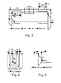
- FIG. 3 An embodiment of the device according to the invention is shown schematically in figures 3 .
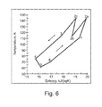
- figure 6 shows the T-S diagram of the device according to the invention with a Brayton cycle for the first heat exchanging medium (helium in this example)
- cryostat cost Attempts to reduce cryostat cost are targeting 0.1-0.2 M €/km, foreseen options include e.g., replacement of outer cryostat shell made of stainless steel with polymer, such as polyethylene [10], etc.
- Outer wall of a cryostat is made of any appropriate material: metal (e.g., stainless steel, e. g. magnetic or non-magnetic), concrete (e.g., ductal or quantz), plastic or their combination.
- metal e.g., stainless steel, e. g. magnetic or non-magnetic
- concrete e.g., ductal or quantz
- Protective layer e.g., line X can be used as well).
- cryostat To ensure low friction of coolant inside the cryostat, along the length cryostat is made semi-flexible, a combination of longer rigid and shorter corrugated tubes (or bellows).
- cryostat can have a tubular or other cross-section, or their mix (e.g., inner wall tubular, outer wall trapezium).
- Integrated MLI is known where separate radiation shields are spaced with an array of posts in particular interconnected to radiation shields or sheets comprising the MLI layers (see e.g.: US8234835 ) and in addition the posts in each layer can be connected to each other with support arms or beams.
- a particular disadvantage of this solution is that the said posts are interconnected to each other in the preferential direction of the heat flux and because they have to transfer mechanical load in the same direction, the contact resistance cannot be made sufficiently low.
- a solid state heat flux of such post in the temperature range 300 K to 70 K
- a heat flux is 3000 W/m2, (which is 30,000 times higher as compared to the target of 0.1 W/m2).
- two permanent magnets PM each 3 mm thick, 5 mm in diameter: 0.18 cm2area
- create a pressure of 5 kgf/cm2 in other words PM density of 0.2 PM/cm2 is in principle sufficient to counteract atmospheric pressure of 1 kgf/cm2 without a post.
- a stable suspension and thus counteraction to atmospheric pressure is created with a PM-ReBCO pair, e.g. with ReBCO superconductor attached to the inner cryostat wall.
- a typical HTS power cable phase (a former, Cu conductor, HTS core, electrical insulation, electric and magnetic shields, liquid nitrogen, etc.) without a cryostat weights 10-20 kg/m.
- Three phases (without a cryostat) weight less than 50 kg/m.
- a typical diameter of three phases is 0.2 m. Therefore a pressure on the cryostat wall due to the cable weight (acting on 1/3 of the cryostat inner wall surface) is about 3 kN/m2 (kPa).
- This pressure can be created by 50/m2 pairs of PM-REBCO (e.g., NdFeB PM diameter 20 mm, 5 mm height, REBCO similar dimensions, each creating a suspension force of 6 kg).
- the proposed interlayer spacer transmits mechanical load using repulsion forces between stationary permanent magnets.
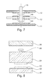
- a column of e.g., ring-shaped permanent magnet clips 4 of one spacer, see fig. 7 . is arranged in such a way that two clips with a reflective layer in between have the same direction of magnetization and therefore attract each other, while clips from two adjacent reflective layers repel each other.
- a pin attached e.g., to the innermost ⁇ LTI layer is used. Such pin does not transmit mechanical load through ⁇ LTI, therefore it has smaller thermal conductance as compared to any other lumped spacer that does.
Landscapes
- Engineering & Computer Science (AREA)
- Physics & Mathematics (AREA)
- Mechanical Engineering (AREA)
- Thermal Sciences (AREA)
- General Engineering & Computer Science (AREA)
- Filling Or Discharging Of Gas Storage Vessels (AREA)
- Superconductors And Manufacturing Methods Therefor (AREA)
Priority Applications (2)
| Application Number | Priority Date | Filing Date | Title |
|---|---|---|---|
| EP14200513.1A EP3040647A1 (de) | 2014-12-30 | 2014-12-30 | Vorrichtung zur Kühlung eines Hochtemperatursupraleiters |
| PCT/EP2015/078787 WO2016107717A1 (en) | 2014-12-30 | 2015-12-07 | Device for cooling a high temperature superconductor |
Applications Claiming Priority (1)
| Application Number | Priority Date | Filing Date | Title |
|---|---|---|---|
| EP14200513.1A EP3040647A1 (de) | 2014-12-30 | 2014-12-30 | Vorrichtung zur Kühlung eines Hochtemperatursupraleiters |
Publications (1)
| Publication Number | Publication Date |
|---|---|
| EP3040647A1 true EP3040647A1 (de) | 2016-07-06 |
Family
ID=52292713
Family Applications (1)
| Application Number | Title | Priority Date | Filing Date |
|---|---|---|---|
| EP14200513.1A Withdrawn EP3040647A1 (de) | 2014-12-30 | 2014-12-30 | Vorrichtung zur Kühlung eines Hochtemperatursupraleiters |
Country Status (2)
| Country | Link |
|---|---|
| EP (1) | EP3040647A1 (de) |
| WO (1) | WO2016107717A1 (de) |
Citations (6)
| Publication number | Priority date | Publication date | Assignee | Title |
|---|---|---|---|---|
| US6425250B1 (en) * | 2001-02-08 | 2002-07-30 | Praxair Technology, Inc. | System for providing cryogenic refrigeration using an upstream pulse tube refrigerator |
| US20070240451A1 (en) * | 2005-09-29 | 2007-10-18 | Fogarty James M | Integration of IGCC plant with superconducting power island |
| US20100024474A1 (en) * | 2007-01-25 | 2010-02-04 | Sander Kaart | Method and apparatus for cooling a hydrocarbon stream |
| US20100275616A1 (en) * | 2007-11-19 | 2010-11-04 | Ihi Corporation | Cryogenic refrigerator and control method therefor |
| US8234835B2 (en) | 2007-03-16 | 2012-08-07 | Quest Product Development Corporation | Integrated multilayer insulation |
| US20140051582A1 (en) | 2012-08-14 | 2014-02-20 | Nexans | Arrangement with at least one superconductive cable |
Family Cites Families (2)
| Publication number | Priority date | Publication date | Assignee | Title |
|---|---|---|---|---|
| JP2001263841A (ja) * | 2000-03-15 | 2001-09-26 | Sumitomo Heavy Ind Ltd | パルス管冷凍機 |
| DK2317526T3 (da) * | 2009-10-30 | 2013-04-15 | Nexans | System med mindst ét kabel med superledningsevne |
-
2014
- 2014-12-30 EP EP14200513.1A patent/EP3040647A1/de not_active Withdrawn
-
2015
- 2015-12-07 WO PCT/EP2015/078787 patent/WO2016107717A1/en not_active Ceased
Patent Citations (6)
| Publication number | Priority date | Publication date | Assignee | Title |
|---|---|---|---|---|
| US6425250B1 (en) * | 2001-02-08 | 2002-07-30 | Praxair Technology, Inc. | System for providing cryogenic refrigeration using an upstream pulse tube refrigerator |
| US20070240451A1 (en) * | 2005-09-29 | 2007-10-18 | Fogarty James M | Integration of IGCC plant with superconducting power island |
| US20100024474A1 (en) * | 2007-01-25 | 2010-02-04 | Sander Kaart | Method and apparatus for cooling a hydrocarbon stream |
| US8234835B2 (en) | 2007-03-16 | 2012-08-07 | Quest Product Development Corporation | Integrated multilayer insulation |
| US20100275616A1 (en) * | 2007-11-19 | 2010-11-04 | Ihi Corporation | Cryogenic refrigerator and control method therefor |
| US20140051582A1 (en) | 2012-08-14 | 2014-02-20 | Nexans | Arrangement with at least one superconductive cable |
Also Published As
| Publication number | Publication date |
|---|---|
| WO2016107717A1 (en) | 2016-07-07 |
Similar Documents
| Publication | Publication Date | Title |
|---|---|---|
| US7453041B2 (en) | Method and apparatus for cooling a superconducting cable | |
| AU2004285058A1 (en) | Conduit component for a power supply network, use thereof, method for transporting cryogenic energy carriers in conduits and devices suitable therefor | |
| Morpurgo | The design of the superconducting magnet for the OMEGA project | |
| CN111819405B (zh) | 用于冷却超导电流载体的方法和设备 | |
| US6342673B1 (en) | Method of maintaining a superconducting cryolink at low temperature | |
| US5570723A (en) | Support system and method for jacketed multiple cryogenic pipes for cyrogenic fluid transfer | |
| JP5907519B2 (ja) | 超伝導送電システムと冷却方法 | |
| Fesmire et al. | Robust multilayer insulation for cryogenic systems | |
| EP3040647A1 (de) | Vorrichtung zur Kühlung eines Hochtemperatursupraleiters | |
| JP2019033056A (ja) | 超電導ケーブル及び液化天然ガス輸送システム | |
| Green | Cooling the MICE magnets using small cryogenic coolers | |
| Hosoyama et al. | Development of a high performance transfer line system | |
| Ivanov et al. | A proposal of the hybrid energy transfer pipe | |
| Squires et al. | Design of the 2 Tesla Superconducting Solenoid for the Fermilab do Detector Upgrade | |
| Eyssa et al. | The potential impact of developing high Tc superconductors on superconductive magnetic energy storage (SMES) | |
| Schoenung et al. | System study of long distance low voltage transmission using high temperature superconducting cable | |
| Hosoyama et al. | Design and performance of KEKB superconducting cavities and its cryogenic system | |
| Gouge et al. | Vacuum-insulated, flexible cryostats for long HTS cables: Requirements, status and prospects | |
| Shu et al. | Developments in advanced and energy saving thermal isolations for cryogenic applications | |
| Green | The operation of a forced two phase cooling system on a large superconducting magnet | |
| Esser et al. | Cryostat Design for the Bent Superconducting Dipole Magnets and Cryogenic Layout for the HESR at FAIR | |
| Green | Cooling the MICE Liquid Hydrogen Absorbers using Small Cryogenic Coolers | |
| Gravil et al. | Operation with the 1.8 K tore supra cryogenic system | |
| Hinterberger et al. | Cryostat for the SSC superferric magnet option | |
| Kim et al. | Cryogenic system for KSTAR Tokamak |
Legal Events
| Date | Code | Title | Description |
|---|---|---|---|
| PUAI | Public reference made under article 153(3) epc to a published international application that has entered the european phase |
Free format text: ORIGINAL CODE: 0009012 |
|
| AK | Designated contracting states |
Kind code of ref document: A1 Designated state(s): AL AT BE BG CH CY CZ DE DK EE ES FI FR GB GR HR HU IE IS IT LI LT LU LV MC MK MT NL NO PL PT RO RS SE SI SK SM TR |
|
| AX | Request for extension of the european patent |
Extension state: BA ME |
|
| 17P | Request for examination filed |
Effective date: 20170104 |
|
| RBV | Designated contracting states (corrected) |
Designated state(s): AL AT BE BG CH CY CZ DE DK EE ES FI FR GB GR HR HU IE IS IT LI LT LU LV MC MK MT NL NO PL PT RO RS SE SI SK SM TR |
|
| STAA | Information on the status of an ep patent application or granted ep patent |
Free format text: STATUS: THE APPLICATION IS DEEMED TO BE WITHDRAWN |
|
| 18D | Application deemed to be withdrawn |
Effective date: 20200701 |