EP3040673A1 - Systeme d'extraction d'obus de mortier - Google Patents
Systeme d'extraction d'obus de mortier Download PDFInfo
- Publication number
- EP3040673A1 EP3040673A1 EP15382001.4A EP15382001A EP3040673A1 EP 3040673 A1 EP3040673 A1 EP 3040673A1 EP 15382001 A EP15382001 A EP 15382001A EP 3040673 A1 EP3040673 A1 EP 3040673A1
- Authority
- EP
- European Patent Office
- Prior art keywords
- extraction system
- shell
- connecting shaft
- movement
- mortar
- Prior art date
- Legal status (The legal status is an assumption and is not a legal conclusion. Google has not performed a legal analysis and makes no representation as to the accuracy of the status listed.)
- Granted
Links
- 238000000605 extraction Methods 0.000 title claims abstract description 73
- 239000004570 mortar (masonry) Substances 0.000 title claims abstract description 52
- 230000005540 biological transmission Effects 0.000 claims description 9
- 230000000977 initiatory effect Effects 0.000 description 2
- 238000000034 method Methods 0.000 description 2
- 230000001419 dependent effect Effects 0.000 description 1
- 238000005474 detonation Methods 0.000 description 1
- 239000002360 explosive Substances 0.000 description 1
- 238000004519 manufacturing process Methods 0.000 description 1
- 239000000463 material Substances 0.000 description 1
- 230000001105 regulatory effect Effects 0.000 description 1
Images




Classifications
-
- F—MECHANICAL ENGINEERING; LIGHTING; HEATING; WEAPONS; BLASTING
- F41—WEAPONS
- F41A—FUNCTIONAL FEATURES OR DETAILS COMMON TO BOTH SMALLARMS AND ORDNANCE, e.g. CANNONS; MOUNTINGS FOR SMALLARMS OR ORDNANCE
- F41A15/00—Cartridge extractors, i.e. devices for pulling cartridges or cartridge cases at least partially out of the cartridge chamber; Cartridge ejectors, i.e. devices for throwing the extracted cartridges or cartridge cases free of the gun
- F41A15/22—Tools for extracting cartridges
Definitions
- the invention relates to a mortar shell extraction system for mortar shells of any caliber, which allows extracting from the mortar a shell that has not been cast out of the mortar and therefore remains inside it.
- the extraction system of the invention allows extracting the shell, complying with safety requirements necessary for such operations, in which manual intervention on a potentially dangerous material due to its internal explosive charge is required.
- the first document discloses an extraction system that uses permanent magnets that work around a rotational shaft for extracting the shell from the mortar tube. This method is incompatible with current shells which have electronic fuses because the use of magnets could initiate the shell during extraction, therefore representing a danger for the user.
- the second patent document discloses an extraction device for extracting shells from inside a mortar tube requiring a cord that can be lowered down the mortar tube together with guiding parts.
- the projectile is extracted by means of a pawl, using a tractive force.
- This device does not allow extracting shells in the event that the surface of said shells is not completely dry, in addition to requiring a process for preparing the extraction device that is complicated and not very safe due to the system of guiding parts and the cord which said device requires.
- the present invention proposes a solution to the aforementioned problems by means of an extraction system according to claim 1.
- the dependent claims define preferred embodiments of the invention.
- the first inventive aspect corresponds to a mortar shell extraction system comprising:
- the gripping means of the extraction system allow holding the shell, said gripping means comprising the components suitable for said holding depending on the type of fuse mounted in any type of mortar shell.
- the driving force is transmitted from the user through the components of the extraction system, particularly the driving means. Said user operates the driving means such that movement occurs, which movement, transmitted along the connecting shaft to the gripping means, is converted into a force such that the gripping means are driven so that they grip the shell, regardless of the configuration of said gripping means.
- the shell extraction system further comprises holding means which make it easier for a user to hold the extraction system.
- the holding means advantageously allow the user to stably retain the extraction system.
- the holding means additionally comprise a length that is suitable for inserting the shell extraction system in the mortar such that the user is far enough away from the line of fire of said mortar, exposing no body part to the line of fire of the mortar when using the system to extract a shell, the system therefore being safer than those extraction systems existing in the state of the art.
- the shell extraction system further comprises actuating means configured for transmitting movement to the driving means.
- actuating means allow the user to operate the driving means in a simpler and more accessible manner.
- the shell extraction system comprises actuating means arranged such that they are capable of performing rotational movement, and the driving means are configured for being driven by the rotational movement of the actuating means and for converting said rotational movement into linear movement which is transmitted to the at least one connecting shaft.
- the actuating means comprise a lever with defined fixed positions between which the user can operate said actuating means.
- the different positions are achieved by rotational movement of the actuating means, particularly of the lever.
- This rotational movement applied for obtaining the change in position of the lever is transmitted to the driving means where it is converted into linear movement, such that said linear movement is transmitted through the at least one connecting shaft to the gripping means and is converted in said gripping means into the gripping force necessary for retaining the shell for extraction.
- the actuating means are movably arranged, and the driving means are configured for being driven by a change in position of the actuating means and for converting said movement into linear movement which is transmitted to the at least one connecting shaft.
- the actuating means have defined fixed positions in which the user can operate said means.
- the different positions are achieved by movement of these actuating means, for example, a movable rod that can move between two positions, an upper position and a lower position.
- This movement applied for obtaining the change in position of the actuating means is transmitted to the driving means where it is converted into linear movement, such that said linear movement is transmitted through the at least one connecting shaft to the gripping means and is converted in said gripping means into the gripping force necessary for extracting the shell.
- the linear movement transmitted to the at least one connecting shaft drives the gripping means for holding the shell.
- This drive advantageously allows converting linear movement into a driving force such that it is sufficient for extracting the shell.
- the connecting shaft is adapted for converting the movement it receives from the driving means into radial clamping movement and for transmitting it to the gripping means.
- the shell extraction system comprises an elastic clamping element allowing perimetral deformation thereof such that it is capable of housing an outer surface of the fuse of the shell by clamping.
- clamping element This advantageously allows regulating the size of the clamping element, the latter being fitted to the outer diameter of the surface of the fuse of the shell.
- the clamping element surrounds the fuse of the shell for extraction thereof.
- the at least one connecting shaft converts the movement it receives from the driving means into rotational movement and transmits it to the gripping means.
- the connecting shaft allows converting the movement applied by the user on the actuating means and received by the driving means and transmitted to said connecting shaft. Transmitting movement from the connecting shaft allows it to reach the gripping means, wherein said transmitted movement is converted into the force of actuation necessary for the extraction of the shell.
- the gripping means comprise a clamp suitable for interlocking with a surface of the fuse of the shell by press fit. Said surface is preferably a notched surface.
- Said clamp allows extracting the shell by means of it acting on a surface of the shell adapted for that purpose.
- the clamp is housed on said surface, preferably a notch, and the driving force on the gripping means allows said clamp to interlock inside the notch by press fit.
- the shell extraction system additionally comprises a safety element located between the holding means and the driving means which allows increasing the distance between the holding means and the path of the mortar.
- the safety system advantageously allows the user to move further away from the path of the mortar, as well as providing the user with easier and faster access to the actuating means.
- the shell extraction system comprises a safety element attached to the holding means by an interface configured for allowing rapid decoupling of the holding means with respect to the safety element and to the rest of the system.
- the interface is an element which allows attaching holding means to the safety element, such that in the event of accidental initiation of the mortar shell during the extraction process, the safety element is separated from the interface and is cast out together with the rest of the extraction system and with the shell, the user keeping the holding means and the interface, which remain attached to one another, held together.
- the shell extraction system comprises a centering element adapted for positioning the extraction system inside the mortar tube.
- Said centering element is mounted on the at least one connecting shaft, before the gripping means.
- said centering element has the same diameter as the mortar tube, such that once it is inserted in said tube, it abuts with the walls of the mortar tube and allows the gripping means to be inserted and properly positioned on the shell in a centered manner.
- Figure 1 shows a first embodiment of the extraction system of the invention.
- the shell extraction system allows removing a shell that has not detonated after an operating failure of said shell inside the mortar. Said shell is housed in the mortar tube, from where it must be safely removed to prevent detonation therein.
- the shell extraction system comprises holding means (1) which allow the user to hold the extraction system during the operation of inserting the system into the mortar and during the operation of extracting the system together with the shell once said shell is gripped by the system in the extraction system usage situation.
- Said holding means (1) allow holding the extraction system such that the user can safely remove the shell.
- the holding means (1) preferably have a length that can be adapted to the length of the mortar tube from where the shell is to be extracted.
- the holding means (1) are attached to a first end of a safety element (2) through an interface.
- the attachment between the holding means (1) and the interface is a threaded attachment.
- the attachment between the interface and the safety element (2) is a diametral fit, which allows the immediate decoupling of the interface from the safety element (2) in the event of the accidental initiation of the mortar shell during the extraction process.
- the safety element (2) is attached at its other end to the actuating means (3), through a connector (26).
- the actuating means (3) allow the user to apply movement which is transmitted to the shell, causing the gripping of the shell to extract it from the mortar.
- the actuating means (3) comprise a lever (23) adapted for performing rotational movement.
- the rotational movement of the lever (23) is transmitted to the driving means (4) as longitudinal movement.
- Said driving means (4) generate the clamping force necessary for holding the shell (A) from the longitudinal movement received from the actuating means (3).
- the actuating means (3) can move between two different positions, according to which positions a movement that allows similar longitudinal movement towards the driving means (4) is generated. Said two positions are separated according to a longitudinal movement.
- the driving means (4) are attached at the other end thereof to a connecting shaft (5), such that the shaft (5) receives the clamping force generated in the driving means (4) and transmits it to the shell for holding said shell.
- the connecting shaft (5) is attached to the gripping means (6) which allow holding the shell to extract it from the mortar.
- the safety element (2) is configured as an element with a bent sector which allows the user of the extractor system to hold it by the holding elements (1) along an axis that is shifted away from the longitudinal axis of the connecting shaft, thereby assuring that no part of the user's body is exposed to the line of fire of the mortar during the shell extraction operation.
- the connecting shaft (5) transmits longitudinal movement from the driving means (4) to the gripping means (6).
- the centering element (7) envisaged in this embodiment advantageously makes it easier for the gripping means (6) to be located in the suitable position inside the mortar (B).
- FIG. 2 shows an embodiment of the gripping means (6), in which the shell is held by clamping, such that the outer surface of the shell, particularly the outer surface of the fuse of the shell, is held by interference through an elastic clamping element (10).
- the gripping means (6) comprise an outer body (8) and an inner body (9).
- the clamping element (10) which is integral with the inner body (9), performs its holding function through the longitudinal movement received from the connecting shaft (5).
- FIG. 3 shows a second embodiment of the gripping means (6) wherein the shell is held by press fit.
- the gripping means (6) comprise a clamp (11) adapted for being clamped onto a holding surface of the shell, for example a notch, an actuator body (12) and a clamp holder (13).
- the clamp (11) allows gripping the shell (A) by means of the housing or interlocking in a notch of the fuse of the shell (A).
- the gripping means (6) are activated through the longitudinal movement received from the connecting shaft (5).
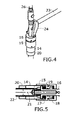
- Figure 4 shows an embodiment of the actuating means (3) which in this case comprise a lever (23), a clamping cam (24) and a connector (26).
- Figure 5 shows an embodiment of the driving means (4) comprising a body (14), a release adapter (15), a coupler (16), an elastic assembly (17), a regulator (18), a guide ring (19) and a clamping nut (20).
- the connecting shaft (5) comprises a transmission rod (21) arranged inside a sleeve (22).
- the driving means (4) are responsible for transmitting rotational movement of the lever (23) as longitudinal movement of the transmission rod (21) along the inside of the sleeve (22).
- the driving means (4) generate the force necessary for gripping the shell from the longitudinal movement of the transmission rod (21) of the connecting shaft (5).
- the transmission rod (21) allows transmitting longitudinal movement from the driving means (4) to the gripping means (6), sliding along the inside of the sleeve (22).
- Figure 6 shows a first step of the extraction process for extracting a shell (A) from inside the mortar (B).
- the user holds the shell extraction system by the holding means (1) and inserts it, according to the longitudinal direction of the mortar (B), into the mortar (B) through the upper part thereof, i.e., through the part of the mortar (B) which has the opening where access for the shell (A) inside same is allowed.
- Figure 7 shows a second step of the extraction process for extracting a shell (A) from inside the mortar (B).
- the gripping means (6) and connecting shaft (5) are housed therein.
- the actuating means (3) and driving means (4) can be accessed from the outside, such that the user can act on said actuating means (3) to generate the force needed to be transmitted, such that the gripping means (6) properly hold the shell (A). Therefore, part of the shell (A) is housed in or surrounded by the gripping means (6), such that it can be extracted.
- Figure 8 shows the position in which the mortar shell (A) is housed inside the gripping means (6), for the case in which gripping is done by clamping.
- Figure 10 shows the position in which the mortar shell (A) is positioned to be surrounded by the gripping means (6) for the case in which gripping is done by press fit.
- the gripping means depicted in Figures 8 and 10 correspond to those shown in Figures 2 and 3 , respectively.
- Figures 10 and 11 show the case of gripping by press fit. Movement of the lever (23) causes the transmission rod (21) to move, causing the clamp (11) to close. Driving the lever (23) to its final position, integral with the clamping cam (24), allows final fixing of the clamp (11).
- Figure 11 shows the final position in which the mortar shell (A) is fixed to the gripping means (6) in the case of gripping by press fit.
Landscapes
- Engineering & Computer Science (AREA)
- General Engineering & Computer Science (AREA)
- Devices For Medical Bathing And Washing (AREA)
- Portable Nailing Machines And Staplers (AREA)
- Toys (AREA)
- Apparatus For Making Beverages (AREA)
- Prostheses (AREA)
- Automatic Assembly (AREA)
- Lining And Supports For Tunnels (AREA)
Priority Applications (9)
| Application Number | Priority Date | Filing Date | Title |
|---|---|---|---|
| ES15382001T ES2706698T3 (es) | 2015-01-02 | 2015-01-02 | Sistema de extracción de granadas |
| EP15382001.4A EP3040673B1 (fr) | 2015-01-02 | 2015-01-02 | Système d'extraction d'obus de mortier |
| PCT/EP2015/081385 WO2016107891A1 (fr) | 2015-01-02 | 2015-12-30 | Système d'extraction d'obus de mortier |
| BR112017014148A BR112017014148A2 (pt) | 2015-01-02 | 2015-12-30 | sistema de extração de projétil |
| RU2017127547A RU2714038C2 (ru) | 2015-01-02 | 2015-12-30 | Устройство для извлечения мины из миномёта |
| CN201580072295.6A CN107429980B (zh) | 2015-01-02 | 2015-12-30 | 迫击炮弹取出系统 |
| US15/541,327 US10234223B2 (en) | 2015-01-02 | 2015-12-30 | Mortar shell extraction system |
| CL2017001725A CL2017001725A1 (es) | 2015-01-02 | 2017-06-29 | Sistema de extracción de granadas de mortero |
| ZA2017/05204A ZA201705204B (en) | 2015-01-02 | 2017-08-01 | Mortar shell extraction system |
Applications Claiming Priority (1)
| Application Number | Priority Date | Filing Date | Title |
|---|---|---|---|
| EP15382001.4A EP3040673B1 (fr) | 2015-01-02 | 2015-01-02 | Système d'extraction d'obus de mortier |
Publications (2)
| Publication Number | Publication Date |
|---|---|
| EP3040673A1 true EP3040673A1 (fr) | 2016-07-06 |
| EP3040673B1 EP3040673B1 (fr) | 2018-10-17 |
Family
ID=53442703
Family Applications (1)
| Application Number | Title | Priority Date | Filing Date |
|---|---|---|---|
| EP15382001.4A Not-in-force EP3040673B1 (fr) | 2015-01-02 | 2015-01-02 | Système d'extraction d'obus de mortier |
Country Status (9)
| Country | Link |
|---|---|
| US (1) | US10234223B2 (fr) |
| EP (1) | EP3040673B1 (fr) |
| CN (1) | CN107429980B (fr) |
| BR (1) | BR112017014148A2 (fr) |
| CL (1) | CL2017001725A1 (fr) |
| ES (1) | ES2706698T3 (fr) |
| RU (1) | RU2714038C2 (fr) |
| WO (1) | WO2016107891A1 (fr) |
| ZA (1) | ZA201705204B (fr) |
Cited By (2)
| Publication number | Priority date | Publication date | Assignee | Title |
|---|---|---|---|---|
| FR3055955A1 (fr) * | 2016-09-13 | 2018-03-16 | Etat Francais Represente Par Le Delegue General Pour L'armement | Dispositif d'extraction de munition pour vehicule equipe d'un systeme d'artillerie |
| EP4198444A1 (fr) * | 2021-12-16 | 2023-06-21 | Thales | Dispositif d'extraction pour munition et procede d'extraction associe |
Families Citing this family (3)
| Publication number | Priority date | Publication date | Assignee | Title |
|---|---|---|---|---|
| EP3040673B1 (fr) | 2015-01-02 | 2018-10-17 | Expal Systems SA | Système d'extraction d'obus de mortier |
| RU179454U1 (ru) * | 2017-05-15 | 2018-05-15 | Федеральное государственное казенное военное образовательное учреждение высшего образования "ВОЕННАЯ АКАДЕМИЯ МАТЕРИАЛЬНО-ТЕХНИЧЕСКОГО ОБЕСПЕЧЕНИЯ имени генерала армии А.В. Хрулева" | Приспособление для извлечения не стреляного патрона |
| FR3097041B1 (fr) * | 2019-06-06 | 2021-05-21 | Thales Sa | Berceau de réception pour munition et procédé d’extraction associé |
Citations (5)
| Publication number | Priority date | Publication date | Assignee | Title |
|---|---|---|---|---|
| US2397554A (en) * | 1944-12-13 | 1946-04-02 | Dudley M Lontz | Handling device |
| FR923289A (fr) * | 1946-01-31 | 1947-07-02 | Brandt Edgar Ets | écouvillon |
| US2770988A (en) | 1952-07-24 | 1956-11-20 | Brandt Soc Nouv Ets | Misfired projectile extractor |
| US5987799A (en) * | 1998-03-12 | 1999-11-23 | Dedeaux; Tina M. | Primitive weapon muzzle loader/unloader device |
| EP1712872A1 (fr) | 2005-04-13 | 2006-10-18 | Rheinmetall Waffe Munition GmbH | Dispositif pout décharger un mortier |
Family Cites Families (13)
| Publication number | Priority date | Publication date | Assignee | Title |
|---|---|---|---|---|
| US4588222A (en) | 1984-08-14 | 1986-05-13 | The United States Of America As Represented By The Secretary Of The Army | Rocket extraction device |
| DE3932131A1 (de) | 1989-09-27 | 1991-04-04 | Rheinmetall Gmbh | Entnahmewerkzeug fuer treibladungsmodule |
| US5419427A (en) * | 1994-01-21 | 1995-05-30 | Feco Engineered Systems, Inc. | Finger chuck assembly and method for processing a hollow article |
| US5825837A (en) * | 1996-03-11 | 1998-10-20 | General Electric Company | Extraction tool for partial length fuel rods in nuclear fuel assemblies |
| DE19801178C2 (de) * | 1998-01-15 | 2000-12-07 | Mwg Biotech Ag | Deckelgreifvorrichtung |
| EP1116559B1 (fr) * | 1999-02-08 | 2005-12-21 | Mitsubishi Denki Kabushiki Kaisha | Procede de fabrication d'une micropince |
| US20040041423A1 (en) * | 2002-08-28 | 2004-03-04 | Cannon Steven Earl | Clamp and method for handling objects |
| RU2254538C1 (ru) * | 2003-10-29 | 2005-06-20 | Пензенский Артиллерийский Инженерный Институт | Механический разрядник для извлечения снаряда из канала ствола артиллерийских орудий среднего калибра |
| US7246540B2 (en) * | 2004-12-30 | 2007-07-24 | Rillera Robert P | Nut and bolt holder and starter |
| DE102005006062A1 (de) * | 2005-02-10 | 2006-08-24 | Rheinmetall Waffe Munition Gmbh | Vorrichtung zum Entladen einer Mörserpatrone |
| RU2006144626A (ru) * | 2006-12-15 | 2008-06-20 | Общевойсковая Академия Вооруженных Сил Российской Федерации (Оа Вс Рф) (Ru) | Устройство для разряжения артиллерийского орудия |
| US8863431B2 (en) | 2012-04-17 | 2014-10-21 | The Otis Patent Trust | Universal patch assembly for cleaning the bores of weapons |
| EP3040673B1 (fr) | 2015-01-02 | 2018-10-17 | Expal Systems SA | Système d'extraction d'obus de mortier |
-
2015
- 2015-01-02 EP EP15382001.4A patent/EP3040673B1/fr not_active Not-in-force
- 2015-01-02 ES ES15382001T patent/ES2706698T3/es active Active
- 2015-12-30 WO PCT/EP2015/081385 patent/WO2016107891A1/fr not_active Ceased
- 2015-12-30 RU RU2017127547A patent/RU2714038C2/ru not_active IP Right Cessation
- 2015-12-30 BR BR112017014148A patent/BR112017014148A2/pt not_active IP Right Cessation
- 2015-12-30 CN CN201580072295.6A patent/CN107429980B/zh not_active Expired - Fee Related
- 2015-12-30 US US15/541,327 patent/US10234223B2/en active Active
-
2017
- 2017-06-29 CL CL2017001725A patent/CL2017001725A1/es unknown
- 2017-08-01 ZA ZA2017/05204A patent/ZA201705204B/en unknown
Patent Citations (5)
| Publication number | Priority date | Publication date | Assignee | Title |
|---|---|---|---|---|
| US2397554A (en) * | 1944-12-13 | 1946-04-02 | Dudley M Lontz | Handling device |
| FR923289A (fr) * | 1946-01-31 | 1947-07-02 | Brandt Edgar Ets | écouvillon |
| US2770988A (en) | 1952-07-24 | 1956-11-20 | Brandt Soc Nouv Ets | Misfired projectile extractor |
| US5987799A (en) * | 1998-03-12 | 1999-11-23 | Dedeaux; Tina M. | Primitive weapon muzzle loader/unloader device |
| EP1712872A1 (fr) | 2005-04-13 | 2006-10-18 | Rheinmetall Waffe Munition GmbH | Dispositif pout décharger un mortier |
Cited By (3)
| Publication number | Priority date | Publication date | Assignee | Title |
|---|---|---|---|---|
| FR3055955A1 (fr) * | 2016-09-13 | 2018-03-16 | Etat Francais Represente Par Le Delegue General Pour L'armement | Dispositif d'extraction de munition pour vehicule equipe d'un systeme d'artillerie |
| EP4198444A1 (fr) * | 2021-12-16 | 2023-06-21 | Thales | Dispositif d'extraction pour munition et procede d'extraction associe |
| FR3130953A1 (fr) * | 2021-12-16 | 2023-06-23 | Thales | Dispositif d’extraction pour munition et procédé d’extraction associé |
Also Published As
| Publication number | Publication date |
|---|---|
| EP3040673B1 (fr) | 2018-10-17 |
| CN107429980B (zh) | 2019-07-19 |
| RU2017127547A3 (fr) | 2019-05-14 |
| RU2017127547A (ru) | 2019-02-04 |
| CL2017001725A1 (es) | 2018-02-02 |
| RU2714038C2 (ru) | 2020-02-11 |
| CN107429980A (zh) | 2017-12-01 |
| BR112017014148A2 (pt) | 2018-03-06 |
| ES2706698T3 (es) | 2019-03-29 |
| WO2016107891A1 (fr) | 2016-07-07 |
| US10234223B2 (en) | 2019-03-19 |
| ZA201705204B (en) | 2019-02-27 |
| US20170370667A1 (en) | 2017-12-28 |
Similar Documents
| Publication | Publication Date | Title |
|---|---|---|
| US10234223B2 (en) | Mortar shell extraction system | |
| NO20111074A1 (no) | Verktøy for håndtering av en beskyttelsesanordning for en subsea konnektor | |
| EP3612786B1 (fr) | Système de retenue de détonateur pour amplificateurs | |
| CN105164866B (zh) | 具有臂指示器的自动拼接件 | |
| EP3058881A3 (fr) | Système chirurgical électromécanique | |
| US20170284581A1 (en) | Locking element for a connector | |
| KR20130056890A (ko) | 리벳 셋팅 공구 | |
| EP1770305A1 (fr) | Serre-câble actionné par une détente | |
| EP3168077A1 (fr) | Dispositif connecteur de câble de véhicule | |
| US20180034250A1 (en) | Pulling Device | |
| CN1864306B (zh) | 使用炸药来固定连接器的工具及其使用方法 | |
| EP4110561B1 (fr) | Robot de démolition | |
| EP3364058A1 (fr) | Structure de raccord | |
| US10018006B2 (en) | Method and device for activating and deactivating a GS-tool | |
| EP4528207A1 (fr) | Ensemble pour arme à feu | |
| US20050126418A1 (en) | Initiation fixture and an initiator assembly including the same | |
| EP2042752A1 (fr) | Dispositif d'ancrage de l'extrémité de la gaine d'un câble Bowden | |
| DK3177886T3 (en) | Device for discharging on the mouth side of a projectile from a gun barrel | |
| CN107839872B (zh) | 一种线位移超控杆结构及其方法 | |
| JP2016082726A (ja) | 間接活線用直線スリーブカバー及びその取付方法 | |
| US20090101689A1 (en) | Placing unit for placing locking ring bolts | |
| EP3462070B1 (fr) | Raccord débrochable | |
| EP2896468A2 (fr) | Dispositif de protection | |
| US2417457A (en) | Shell separator for semifixed ammunition | |
| WO2013154624A2 (fr) | Appareil, procédé et système pour un dispositif de lancement lancé de manière balistique |
Legal Events
| Date | Code | Title | Description |
|---|---|---|---|
| PUAI | Public reference made under article 153(3) epc to a published international application that has entered the european phase |
Free format text: ORIGINAL CODE: 0009012 |
|
| AK | Designated contracting states |
Kind code of ref document: A1 Designated state(s): AL AT BE BG CH CY CZ DE DK EE ES FI FR GB GR HR HU IE IS IT LI LT LU LV MC MK MT NL NO PL PT RO RS SE SI SK SM TR |
|
| AX | Request for extension of the european patent |
Extension state: BA ME |
|
| STAA | Information on the status of an ep patent application or granted ep patent |
Free format text: STATUS: REQUEST FOR EXAMINATION WAS MADE |
|
| 17P | Request for examination filed |
Effective date: 20170103 |
|
| RBV | Designated contracting states (corrected) |
Designated state(s): AL AT BE BG CH CY CZ DE DK EE ES FI FR GB GR HR HU IE IS IT LI LT LU LV MC MK MT NL NO PL PT RO RS SE SI SK SM TR |
|
| GRAP | Despatch of communication of intention to grant a patent |
Free format text: ORIGINAL CODE: EPIDOSNIGR1 |
|
| STAA | Information on the status of an ep patent application or granted ep patent |
Free format text: STATUS: GRANT OF PATENT IS INTENDED |
|
| INTG | Intention to grant announced |
Effective date: 20180403 |
|
| GRAS | Grant fee paid |
Free format text: ORIGINAL CODE: EPIDOSNIGR3 |
|
| GRAJ | Information related to disapproval of communication of intention to grant by the applicant or resumption of examination proceedings by the epo deleted |
Free format text: ORIGINAL CODE: EPIDOSDIGR1 |
|
| GRAL | Information related to payment of fee for publishing/printing deleted |
Free format text: ORIGINAL CODE: EPIDOSDIGR3 |
|
| STAA | Information on the status of an ep patent application or granted ep patent |
Free format text: STATUS: REQUEST FOR EXAMINATION WAS MADE |
|
| GRAR | Information related to intention to grant a patent recorded |
Free format text: ORIGINAL CODE: EPIDOSNIGR71 |
|
| STAA | Information on the status of an ep patent application or granted ep patent |
Free format text: STATUS: GRANT OF PATENT IS INTENDED |
|
| GRAA | (expected) grant |
Free format text: ORIGINAL CODE: 0009210 |
|
| STAA | Information on the status of an ep patent application or granted ep patent |
Free format text: STATUS: THE PATENT HAS BEEN GRANTED |
|
| INTC | Intention to grant announced (deleted) | ||
| INTG | Intention to grant announced |
Effective date: 20180906 |
|
| AK | Designated contracting states |
Kind code of ref document: B1 Designated state(s): AL AT BE BG CH CY CZ DE DK EE ES FI FR GB GR HR HU IE IS IT LI LT LU LV MC MK MT NL NO PL PT RO RS SE SI SK SM TR |
|
| REG | Reference to a national code |
Ref country code: GB Ref legal event code: FG4D |
|
| REG | Reference to a national code |
Ref country code: CH Ref legal event code: EP |
|
| REG | Reference to a national code |
Ref country code: IE Ref legal event code: FG4D |
|
| REG | Reference to a national code |
Ref country code: AT Ref legal event code: REF Ref document number: 1054572 Country of ref document: AT Kind code of ref document: T Effective date: 20181115 Ref country code: DE Ref legal event code: R096 Ref document number: 602015018236 Country of ref document: DE |
|
| REG | Reference to a national code |
Ref country code: NL Ref legal event code: MP Effective date: 20181017 |
|
| REG | Reference to a national code |
Ref country code: LT Ref legal event code: MG4D |
|
| REG | Reference to a national code |
Ref country code: AT Ref legal event code: MK05 Ref document number: 1054572 Country of ref document: AT Kind code of ref document: T Effective date: 20181017 |
|
| PG25 | Lapsed in a contracting state [announced via postgrant information from national office to epo] |
Ref country code: NL Free format text: LAPSE BECAUSE OF FAILURE TO SUBMIT A TRANSLATION OF THE DESCRIPTION OR TO PAY THE FEE WITHIN THE PRESCRIBED TIME-LIMIT Effective date: 20181017 |
|
| REG | Reference to a national code |
Ref country code: ES Ref legal event code: FG2A Ref document number: 2706698 Country of ref document: ES Kind code of ref document: T3 Effective date: 20190329 |
|
| PG25 | Lapsed in a contracting state [announced via postgrant information from national office to epo] |
Ref country code: FI Free format text: LAPSE BECAUSE OF FAILURE TO SUBMIT A TRANSLATION OF THE DESCRIPTION OR TO PAY THE FEE WITHIN THE PRESCRIBED TIME-LIMIT Effective date: 20181017 Ref country code: LV Free format text: LAPSE BECAUSE OF FAILURE TO SUBMIT A TRANSLATION OF THE DESCRIPTION OR TO PAY THE FEE WITHIN THE PRESCRIBED TIME-LIMIT Effective date: 20181017 Ref country code: AT Free format text: LAPSE BECAUSE OF FAILURE TO SUBMIT A TRANSLATION OF THE DESCRIPTION OR TO PAY THE FEE WITHIN THE PRESCRIBED TIME-LIMIT Effective date: 20181017 Ref country code: HR Free format text: LAPSE BECAUSE OF FAILURE TO SUBMIT A TRANSLATION OF THE DESCRIPTION OR TO PAY THE FEE WITHIN THE PRESCRIBED TIME-LIMIT Effective date: 20181017 Ref country code: NO Free format text: LAPSE BECAUSE OF FAILURE TO SUBMIT A TRANSLATION OF THE DESCRIPTION OR TO PAY THE FEE WITHIN THE PRESCRIBED TIME-LIMIT Effective date: 20190117 Ref country code: BG Free format text: LAPSE BECAUSE OF FAILURE TO SUBMIT A TRANSLATION OF THE DESCRIPTION OR TO PAY THE FEE WITHIN THE PRESCRIBED TIME-LIMIT Effective date: 20190117 Ref country code: PL Free format text: LAPSE BECAUSE OF FAILURE TO SUBMIT A TRANSLATION OF THE DESCRIPTION OR TO PAY THE FEE WITHIN THE PRESCRIBED TIME-LIMIT Effective date: 20181017 Ref country code: LT Free format text: LAPSE BECAUSE OF FAILURE TO SUBMIT A TRANSLATION OF THE DESCRIPTION OR TO PAY THE FEE WITHIN THE PRESCRIBED TIME-LIMIT Effective date: 20181017 Ref country code: IS Free format text: LAPSE BECAUSE OF FAILURE TO SUBMIT A TRANSLATION OF THE DESCRIPTION OR TO PAY THE FEE WITHIN THE PRESCRIBED TIME-LIMIT Effective date: 20190217 |
|
| PG25 | Lapsed in a contracting state [announced via postgrant information from national office to epo] |
Ref country code: PT Free format text: LAPSE BECAUSE OF FAILURE TO SUBMIT A TRANSLATION OF THE DESCRIPTION OR TO PAY THE FEE WITHIN THE PRESCRIBED TIME-LIMIT Effective date: 20190217 Ref country code: GR Free format text: LAPSE BECAUSE OF FAILURE TO SUBMIT A TRANSLATION OF THE DESCRIPTION OR TO PAY THE FEE WITHIN THE PRESCRIBED TIME-LIMIT Effective date: 20190118 Ref country code: AL Free format text: LAPSE BECAUSE OF FAILURE TO SUBMIT A TRANSLATION OF THE DESCRIPTION OR TO PAY THE FEE WITHIN THE PRESCRIBED TIME-LIMIT Effective date: 20181017 Ref country code: RS Free format text: LAPSE BECAUSE OF FAILURE TO SUBMIT A TRANSLATION OF THE DESCRIPTION OR TO PAY THE FEE WITHIN THE PRESCRIBED TIME-LIMIT Effective date: 20181017 Ref country code: SE Free format text: LAPSE BECAUSE OF FAILURE TO SUBMIT A TRANSLATION OF THE DESCRIPTION OR TO PAY THE FEE WITHIN THE PRESCRIBED TIME-LIMIT Effective date: 20181017 |
|
| REG | Reference to a national code |
Ref country code: DE Ref legal event code: R097 Ref document number: 602015018236 Country of ref document: DE |
|
| PG25 | Lapsed in a contracting state [announced via postgrant information from national office to epo] |
Ref country code: CZ Free format text: LAPSE BECAUSE OF FAILURE TO SUBMIT A TRANSLATION OF THE DESCRIPTION OR TO PAY THE FEE WITHIN THE PRESCRIBED TIME-LIMIT Effective date: 20181017 Ref country code: DK Free format text: LAPSE BECAUSE OF FAILURE TO SUBMIT A TRANSLATION OF THE DESCRIPTION OR TO PAY THE FEE WITHIN THE PRESCRIBED TIME-LIMIT Effective date: 20181017 Ref country code: IT Free format text: LAPSE BECAUSE OF FAILURE TO SUBMIT A TRANSLATION OF THE DESCRIPTION OR TO PAY THE FEE WITHIN THE PRESCRIBED TIME-LIMIT Effective date: 20181017 |
|
| PLBE | No opposition filed within time limit |
Free format text: ORIGINAL CODE: 0009261 |
|
| STAA | Information on the status of an ep patent application or granted ep patent |
Free format text: STATUS: NO OPPOSITION FILED WITHIN TIME LIMIT |
|
| PG25 | Lapsed in a contracting state [announced via postgrant information from national office to epo] |
Ref country code: MC Free format text: LAPSE BECAUSE OF FAILURE TO SUBMIT A TRANSLATION OF THE DESCRIPTION OR TO PAY THE FEE WITHIN THE PRESCRIBED TIME-LIMIT Effective date: 20181017 Ref country code: RO Free format text: LAPSE BECAUSE OF FAILURE TO SUBMIT A TRANSLATION OF THE DESCRIPTION OR TO PAY THE FEE WITHIN THE PRESCRIBED TIME-LIMIT Effective date: 20181017 Ref country code: EE Free format text: LAPSE BECAUSE OF FAILURE TO SUBMIT A TRANSLATION OF THE DESCRIPTION OR TO PAY THE FEE WITHIN THE PRESCRIBED TIME-LIMIT Effective date: 20181017 Ref country code: SK Free format text: LAPSE BECAUSE OF FAILURE TO SUBMIT A TRANSLATION OF THE DESCRIPTION OR TO PAY THE FEE WITHIN THE PRESCRIBED TIME-LIMIT Effective date: 20181017 Ref country code: SM Free format text: LAPSE BECAUSE OF FAILURE TO SUBMIT A TRANSLATION OF THE DESCRIPTION OR TO PAY THE FEE WITHIN THE PRESCRIBED TIME-LIMIT Effective date: 20181017 |
|
| REG | Reference to a national code |
Ref country code: CH Ref legal event code: PL |
|
| 26N | No opposition filed |
Effective date: 20190718 |
|
| PG25 | Lapsed in a contracting state [announced via postgrant information from national office to epo] |
Ref country code: LU Free format text: LAPSE BECAUSE OF NON-PAYMENT OF DUE FEES Effective date: 20190102 |
|
| REG | Reference to a national code |
Ref country code: BE Ref legal event code: MM Effective date: 20190131 |
|
| REG | Reference to a national code |
Ref country code: IE Ref legal event code: MM4A |
|
| PG25 | Lapsed in a contracting state [announced via postgrant information from national office to epo] |
Ref country code: SI Free format text: LAPSE BECAUSE OF FAILURE TO SUBMIT A TRANSLATION OF THE DESCRIPTION OR TO PAY THE FEE WITHIN THE PRESCRIBED TIME-LIMIT Effective date: 20181017 |
|
| PG25 | Lapsed in a contracting state [announced via postgrant information from national office to epo] |
Ref country code: BE Free format text: LAPSE BECAUSE OF NON-PAYMENT OF DUE FEES Effective date: 20190131 |
|
| PG25 | Lapsed in a contracting state [announced via postgrant information from national office to epo] |
Ref country code: CH Free format text: LAPSE BECAUSE OF NON-PAYMENT OF DUE FEES Effective date: 20190131 Ref country code: LI Free format text: LAPSE BECAUSE OF NON-PAYMENT OF DUE FEES Effective date: 20190131 |
|
| PG25 | Lapsed in a contracting state [announced via postgrant information from national office to epo] |
Ref country code: IE Free format text: LAPSE BECAUSE OF NON-PAYMENT OF DUE FEES Effective date: 20190102 |
|
| PG25 | Lapsed in a contracting state [announced via postgrant information from national office to epo] |
Ref country code: TR Free format text: LAPSE BECAUSE OF FAILURE TO SUBMIT A TRANSLATION OF THE DESCRIPTION OR TO PAY THE FEE WITHIN THE PRESCRIBED TIME-LIMIT Effective date: 20181017 |
|
| PGFP | Annual fee paid to national office [announced via postgrant information from national office to epo] |
Ref country code: DE Payment date: 20200129 Year of fee payment: 6 Ref country code: GB Payment date: 20200127 Year of fee payment: 6 Ref country code: ES Payment date: 20200224 Year of fee payment: 6 |
|
| PG25 | Lapsed in a contracting state [announced via postgrant information from national office to epo] |
Ref country code: MT Free format text: LAPSE BECAUSE OF NON-PAYMENT OF DUE FEES Effective date: 20190102 |
|
| PGFP | Annual fee paid to national office [announced via postgrant information from national office to epo] |
Ref country code: FR Payment date: 20200127 Year of fee payment: 6 |
|
| PG25 | Lapsed in a contracting state [announced via postgrant information from national office to epo] |
Ref country code: CY Free format text: LAPSE BECAUSE OF FAILURE TO SUBMIT A TRANSLATION OF THE DESCRIPTION OR TO PAY THE FEE WITHIN THE PRESCRIBED TIME-LIMIT Effective date: 20181017 |
|
| PG25 | Lapsed in a contracting state [announced via postgrant information from national office to epo] |
Ref country code: HU Free format text: LAPSE BECAUSE OF FAILURE TO SUBMIT A TRANSLATION OF THE DESCRIPTION OR TO PAY THE FEE WITHIN THE PRESCRIBED TIME-LIMIT; INVALID AB INITIO Effective date: 20150102 |
|
| REG | Reference to a national code |
Ref country code: DE Ref legal event code: R119 Ref document number: 602015018236 Country of ref document: DE |
|
| GBPC | Gb: european patent ceased through non-payment of renewal fee |
Effective date: 20210102 |
|
| PG25 | Lapsed in a contracting state [announced via postgrant information from national office to epo] |
Ref country code: FR Free format text: LAPSE BECAUSE OF NON-PAYMENT OF DUE FEES Effective date: 20210131 |
|
| PG25 | Lapsed in a contracting state [announced via postgrant information from national office to epo] |
Ref country code: GB Free format text: LAPSE BECAUSE OF NON-PAYMENT OF DUE FEES Effective date: 20210102 Ref country code: DE Free format text: LAPSE BECAUSE OF NON-PAYMENT OF DUE FEES Effective date: 20210803 |
|
| REG | Reference to a national code |
Ref country code: ES Ref legal event code: FD2A Effective date: 20220413 |
|
| PG25 | Lapsed in a contracting state [announced via postgrant information from national office to epo] |
Ref country code: MK Free format text: LAPSE BECAUSE OF FAILURE TO SUBMIT A TRANSLATION OF THE DESCRIPTION OR TO PAY THE FEE WITHIN THE PRESCRIBED TIME-LIMIT Effective date: 20181017 |
|
| PG25 | Lapsed in a contracting state [announced via postgrant information from national office to epo] |
Ref country code: ES Free format text: LAPSE BECAUSE OF NON-PAYMENT OF DUE FEES Effective date: 20210103 |