EP3040721A1 - Bouchon de flacon et procédé permettant d'éliminer des composants de la matrice à partir d'un échantillon liquide - Google Patents
Bouchon de flacon et procédé permettant d'éliminer des composants de la matrice à partir d'un échantillon liquide Download PDFInfo
- Publication number
- EP3040721A1 EP3040721A1 EP15201962.6A EP15201962A EP3040721A1 EP 3040721 A1 EP3040721 A1 EP 3040721A1 EP 15201962 A EP15201962 A EP 15201962A EP 3040721 A1 EP3040721 A1 EP 3040721A1
- Authority
- EP
- European Patent Office
- Prior art keywords
- sample
- vial
- liquid sample
- filter plug
- vial cap
- Prior art date
- Legal status (The legal status is an assumption and is not a legal conclusion. Google has not performed a legal analysis and makes no representation as to the accuracy of the status listed.)
- Granted
Links
Images
Classifications
-
- G—PHYSICS
- G01—MEASURING; TESTING
- G01N—INVESTIGATING OR ANALYSING MATERIALS BY DETERMINING THEIR CHEMICAL OR PHYSICAL PROPERTIES
- G01N30/00—Investigating or analysing materials by separation into components using adsorption, absorption or similar phenomena or using ion-exchange, e.g. chromatography or field flow fractionation
- G01N30/96—Investigating or analysing materials by separation into components using adsorption, absorption or similar phenomena or using ion-exchange, e.g. chromatography or field flow fractionation using ion-exchange
-
- B—PERFORMING OPERATIONS; TRANSPORTING
- B65—CONVEYING; PACKING; STORING; HANDLING THIN OR FILAMENTARY MATERIAL
- B65D—CONTAINERS FOR STORAGE OR TRANSPORT OF ARTICLES OR MATERIALS, e.g. BAGS, BARRELS, BOTTLES, BOXES, CANS, CARTONS, CRATES, DRUMS, JARS, TANKS, HOPPERS, FORWARDING CONTAINERS; ACCESSORIES, CLOSURES, OR FITTINGS THEREFOR; PACKAGING ELEMENTS; PACKAGES
- B65D51/00—Closures not otherwise provided for
- B65D51/18—Arrangements of closures with protective outer cap-like covers or of two or more co-operating closures
-
- G—PHYSICS
- G01—MEASURING; TESTING
- G01N—INVESTIGATING OR ANALYSING MATERIALS BY DETERMINING THEIR CHEMICAL OR PHYSICAL PROPERTIES
- G01N30/00—Investigating or analysing materials by separation into components using adsorption, absorption or similar phenomena or using ion-exchange, e.g. chromatography or field flow fractionation
- G01N30/02—Column chromatography
- G01N30/04—Preparation or injection of sample to be analysed
- G01N30/06—Preparation
-
- G—PHYSICS
- G01—MEASURING; TESTING
- G01N—INVESTIGATING OR ANALYSING MATERIALS BY DETERMINING THEIR CHEMICAL OR PHYSICAL PROPERTIES
- G01N30/00—Investigating or analysing materials by separation into components using adsorption, absorption or similar phenomena or using ion-exchange, e.g. chromatography or field flow fractionation
- G01N30/02—Column chromatography
- G01N30/04—Preparation or injection of sample to be analysed
- G01N30/06—Preparation
- G01N30/14—Preparation by elimination of some components
-
- G—PHYSICS
- G01—MEASURING; TESTING
- G01N—INVESTIGATING OR ANALYSING MATERIALS BY DETERMINING THEIR CHEMICAL OR PHYSICAL PROPERTIES
- G01N30/00—Investigating or analysing materials by separation into components using adsorption, absorption or similar phenomena or using ion-exchange, e.g. chromatography or field flow fractionation
- G01N30/02—Column chromatography
- G01N30/60—Construction of the column
- G01N30/6004—Construction of the column end pieces
-
- G—PHYSICS
- G01—MEASURING; TESTING
- G01N—INVESTIGATING OR ANALYSING MATERIALS BY DETERMINING THEIR CHEMICAL OR PHYSICAL PROPERTIES
- G01N30/00—Investigating or analysing materials by separation into components using adsorption, absorption or similar phenomena or using ion-exchange, e.g. chromatography or field flow fractionation
- G01N30/02—Column chromatography
- G01N30/60—Construction of the column
- G01N30/6052—Construction of the column body
- G01N30/6065—Construction of the column body with varying cross section
-
- B—PERFORMING OPERATIONS; TRANSPORTING
- B01—PHYSICAL OR CHEMICAL PROCESSES OR APPARATUS IN GENERAL
- B01L—CHEMICAL OR PHYSICAL LABORATORY APPARATUS FOR GENERAL USE
- B01L3/00—Containers or dishes for laboratory use, e.g. laboratory glassware; Droppers
- B01L3/50—Containers for the purpose of retaining a material to be analysed, e.g. test tubes
- B01L3/502—Containers for the purpose of retaining a material to be analysed, e.g. test tubes with fluid transport, e.g. in multi-compartment structures
-
- G—PHYSICS
- G01—MEASURING; TESTING
- G01N—INVESTIGATING OR ANALYSING MATERIALS BY DETERMINING THEIR CHEMICAL OR PHYSICAL PROPERTIES
- G01N30/00—Investigating or analysing materials by separation into components using adsorption, absorption or similar phenomena or using ion-exchange, e.g. chromatography or field flow fractionation
- G01N2030/009—Extraction
-
- G—PHYSICS
- G01—MEASURING; TESTING
- G01N—INVESTIGATING OR ANALYSING MATERIALS BY DETERMINING THEIR CHEMICAL OR PHYSICAL PROPERTIES
- G01N30/00—Investigating or analysing materials by separation into components using adsorption, absorption or similar phenomena or using ion-exchange, e.g. chromatography or field flow fractionation
- G01N30/02—Column chromatography
- G01N30/04—Preparation or injection of sample to be analysed
- G01N30/06—Preparation
- G01N2030/065—Preparation using different phases to separate parts of sample
-
- G—PHYSICS
- G01—MEASURING; TESTING
- G01N—INVESTIGATING OR ANALYSING MATERIALS BY DETERMINING THEIR CHEMICAL OR PHYSICAL PROPERTIES
- G01N30/00—Investigating or analysing materials by separation into components using adsorption, absorption or similar phenomena or using ion-exchange, e.g. chromatography or field flow fractionation
- G01N30/02—Column chromatography
- G01N30/04—Preparation or injection of sample to be analysed
- G01N30/06—Preparation
- G01N30/14—Preparation by elimination of some components
- G01N2030/143—Preparation by elimination of some components selective absorption
-
- G—PHYSICS
- G01—MEASURING; TESTING
- G01N—INVESTIGATING OR ANALYSING MATERIALS BY DETERMINING THEIR CHEMICAL OR PHYSICAL PROPERTIES
- G01N30/00—Investigating or analysing materials by separation into components using adsorption, absorption or similar phenomena or using ion-exchange, e.g. chromatography or field flow fractionation
- G01N30/02—Column chromatography
- G01N30/04—Preparation or injection of sample to be analysed
- G01N30/24—Automatic injection systems
Definitions
- Chromatography is a widely used analytical technique for the chemical analysis and separation of molecules. Chromatography involves the separation of one or more analyte species from other matrix component present in a sample.
- a stationary phase of a chromatography column is typically selected so that there is an interaction with the analyte. Such interactions can be ionic, hydrophilic, hydrophobic, or combinations thereof.
- the stationary phase can be derivatized with ionic moieties that ideally will bind to ionic analytes and matrix components with varying levels of affinity.
- a mobile phase is percolated through the stationary phase and competes with the analyte and matrix components for binding to the ionic moieties.
- the mobile phase is a term used to describe a liquid solvent or buffer solution that is pumped into a chromatography column inlet.
- the analyte and matrix components will elute off of the stationary phase as a function of time and then be subsequently detected at a detector.
- Examples of some typical detectors are a conductivity detector, a UV-VIS spectrophotometer, and a mass spectrometer.
- chromatography has developed into a powerful analytical tool that is useful for creating a healthier, cleaner, and safer environment where complex sample mixtures can be separated and analyzed for various industries such as water quality, environmental monitoring, food analysis, pharmaceutical, and biotechnology.
- a sample can have a relatively high concentration of a matrix component compared to the analyte concentration. This can cause an interference and prevent an accurate analysis of the analyte within the sample.
- an excessively high matrix concentration can saturate the conductivity detector skewing the baseline response of the analyte peak of a chromatogram.
- a matrix component can generate a chromatographic peak that overlaps with the analyte peak, and thus, interfere with the analysis.
- An example of matrix component can be an ion such as chloride in the trace analysis of perchlorate.
- the liquid sample will typically be pre-treated to remove or reduce a high concentration of a matrix component like chloride.
- Another example of a matrix component can be a hydrophobic species such as sodium lauryl sulfate in the analysis of anions such as chloride and sulfate.
- Solid phase extraction is a type of sample pre-treatment that can be used to remove matrix component from a sample.
- Some solid phase extraction devices require a significant amount of pressure to pass a liquid sample through the solid phase extraction device, which is not well-suited to automated sample pre-treatment with auto-samplers.
- Other solid phase extraction devices that do not require a significant amount of pressure cannot bind a significant amount of matrix component because of low capacity.
- a relatively low dead volume is useful where there is a limited volume of a sample to pre-treat.
- Applicant believes that there is a need for solid phase extraction materials that have a high capacity per unit volume sufficient to pre-treat a single sample, require a relatively low pressure (i.e., less than 100 PSI), and have a compact size so that it can be adapted to existing auto-sampling instruments. Applicant also believes that the extraction material should be low cost so that it is single use and disposable circumventing the need to clean the extraction material after the extraction.
- the vial cap for removing a matrix component from a liquid sample and transferring the liquid sample in a sample vial to an injection valve at the same time.
- the vial cap includes a cap body, an inlet portion, and an outlet portion.
- the cap body includes a liquid sample passageway, and an outer periphery configured to have a slidable gas and liquid seal with a side wall of a sample vial.
- the sample vial includes a side wall, a bottom wall, and an inlet opening.
- the inlet portion is configured to receive a pressurized liquid sample from the sample vial where the liquid sample flows into the liquid sample passageway.
- the inlet portion includes a counterbore section. The counterbore section can hold a filter plug.
- the filter plug includes a polyethylene resin and a material selected from the group consisting of an ion exchange material and a reversed-phase material. In another embodiment, the material may be a combination of an ion exchange material and a reversed-phase material.
- the outlet portion can be configured to output the liquid sample from the liquid sample passageway that has passed through the filter plug.
- the outlet portion includes a plunger section configured to receive a downward force into a sample vial to pressurize the liquid sample within the sample vial.
- the matrix component is selected from the group consisting of an ionic species, a hydrophobic species, and a combination thereof.
- the reversed-phase material is configured to bind an ion pairing agent.
- the reversed-phase material is also configured to bind the matrix component where the matrix component is hydrophobic.
- the polyethylene resin can include a high density polyethylene and the ion exchange material can include a crosslinked styrene sulfonate.
- the polyethylene resin can include a high density polyethylene and the ion exchange material can include a crosslinked copolymer of a vinylbenzylchloride and a divinylbenzene where the crosslinked copolymer is quaternized with a trimethylamine.
- the polyethylene resin can include a high density polyethylene and the ion exchange material can include a crosslinked copolymer of a chloromethylated styrene quaternized with a tertiary amine and a divinylbenzene.
- the polyethylene resin can include a high density polyethylene and the reversed-phase material can include a divinylbenzene resin treated with an ion pairing agent selected from the group consisting of a hexane sulfonate, octane sulfonate, dodecane sulfonate, tetrapropylammonium, tetrabutylammonium, tetrapentylammonium, trifluoroacetate, heptafluorobutyrate, dodecylsulfate, and combinations thereof.
- an ion pairing agent selected from the group consisting of a hexane sulfonate, octane sulfonate, dodecane sulfonate, tetrapropylammonium, tetrabutylammonium, tetrapentylammonium, trifluoroacetate, heptafluorobutyrate, dode
- the polyethylene resin can include a high density polyethylene and the ion exchange material can include a crosslinked styrene sulfonate treated with an anion exchange latex.
- the polyethylene resin can include a high density polyethylene and the ion exchange material can include a positively charged crosslinked polymer treated with a cation exchange latex.
- the positively charged crosslinked polymer is selected from the group consisting of a copolymer of a vinylbenzylchloride and a divinylbenzene where the crosslinked copolymer that is quaternized with a trimethylamine, and a crosslinked copolymer of a chloromethylated styrene quaternized with a tertiary amine and a divinylbenzene.
- the plunger section is a socket configured to receive a plunger.
- the plunger is configured to apply a downward force to the vial cap and transfer the liquid sample through a hollow portion of the plunger.
- a method of removing a matrix component from a liquid sample is described using one of the above described vial caps.
- the method includes adding the liquid sample to a sample vial.
- the vial cap is pushed through the inlet opening of the sample vial towards the bottom wall to pressurize the liquid sample within the sample vial.
- the liquid sample is displaced into the inlet portion, through the filter plug, and out of the outlet portion.
- a portion of the matrix component is removed from the liquid sample with the filter plug.
- the pressure within the sample vial is less than 100 PSI.
- it further includes disposing the vial cap along with the filter plug.
- the liquid sample includes particles
- the method further includes the removing of a portion of the particles from the liquid sample with the filter plug.
- the removed portion of the matrix component is greater than 50% of the matrix component present in the liquid sample before the liquid sample displacing.
- it further includes loading a sample loop on an injection valve with the displaced liquid sample.
- the liquid sample can then be injected in the sample loop to a chromatographic separation device.
- At least one analyte is separated from the matrix components in the liquid sample on the chromatographic separation device.
- An analyte separated from the matrix components is detected at a detector.
- a filter plug can be a porous material used to filter a liquid sample.
- matrix components can be retained by the filter plug so that the filtered liquid sample (i.e., filtrate) has a substantial portion of the matrix components removed. In an embodiment, a substantial portion or substantially all may represent greater than 50%.
- the filter plug can also remove particles from the liquid sample at the same time.
- the filter plug can include a polyethylene resin and a material such as an ion exchange material, a reversed-phase material, or a combination thereof.
- the ion exchange material may be an anion exchange material or a cation exchange material.
- the ion exchange material is configured to bind anions or cations from the liquid sample.
- the reversed-phase material is configured to bind hydrophobic material from the liquid sample.
- polyethylene resin can be in the form of particles, which are fused together at elevated temperatures to bind ion exchange particles or reversed-phase particles.
- the polyethylene resin may be a high density polyethylene (HDPE).
- the density of HDPE can range from 0.93 to 0.97 g/cm 3 . Although the density of HDPE is only marginally higher than that of low density polyethylene (LDPE), HDPE has little branching, giving it stronger intermolecular forces and tensile strength than LDPE.
- HDPE resin other materials that may be suitable for use in the filter plugs described herein include polypropylene resin, polytetrafluoroethylene (PTFE), polyvinylidene fluoride (PVDF), ethyl vinylacetate (EVA), polycarbonate and polycarbonate alloys, nylon 6, thermoplastic polyurethane (TPU), and polyether sulfone (PES).
- PTFE polytetrafluoroethylene
- PVDF polyvinylidene fluoride
- EVA ethyl vinylacetate
- TPU thermoplastic polyurethane
- PES polyether sulfone
- the ion exchange resin may be one of the following types such as a strong cation exchange, weak cation exchange, strong anion exchange, and weak anion exchange.
- the resin may be in a salt form of a cation exchange resin such as, for example, a sodium form.
- the ion exchange resin includes a substrate that is insoluble in water and typically in the form of approximately spherical beads.
- the beads may have a diameter ranging from about 2 microns to about 100 microns, preferably ranging from about 2 microns to about 50 microns, and more preferably ranging from about 10 microns to about 35 microns.
- the ion exchange resin may have a pore size ranging from about 10 angstroms to about 2000 angstroms.
- the ion exchange material may include a crosslinked styrene sulfonate particle.
- the particle size can be about 35 microns in diameter and be in the sodium form.
- the sulfonate groups on the particles act as the cation exchange groups.
- a crosslinked copolymer of a vinylbenzylchloride and a divinylbenzene can be used where the crosslinked copolymer is quaternized with a tertiary amine.
- the anion exchange material can be prepared via chloromethylation of a crosslinked copolymer of styrene and divinylbenzene where the crosslinked copolymer is quaternized with a tertiary amine.
- tertiary amines are trimethylamine and dimethylethanolamine.
- the particle size can be about 35 microns in diameter and be in the chloride form.
- the reversed-phase material may be a copolymer of styrene and divinyl benzene. More broadly, the reversed-phase polymer can be synthesized from a wide variety of polyunsaturated monomers including divinylbenzene, trivinylbenzene and the like, and the preferred monoethylenically unsaturated monomers including styrene, the o, m, and p-methyl styrenes, and o, m, and p-ethyl styrenes, ethylvinylbenzene, vinylnaphthalene and vinyltoluene.
- polyunsaturated monomers including divinylbenzene, trivinylbenzene and the like
- monoethylenically unsaturated monomers including styrene, the o, m, and p-methyl styrenes, and o, m, and p-ethyl sty
- Suitable reversed-phase polymers can also be derived from aliphatic polyunsaturated monomers such as diacrylates and dimethacrylates, including ethylene glycol diacrylate, ethylene glycol dimethacrylate, trimethylolpropane trimethacrylate, neopentyl glycol dimethacrylate, divinylketone, divinyl sulfide, allyl acrylate, diallyl maleate, diallyl fumarate, and the like.
- diacrylates and dimethacrylates including ethylene glycol diacrylate, ethylene glycol dimethacrylate, trimethylolpropane trimethacrylate, neopentyl glycol dimethacrylate, divinylketone, divinyl sulfide, allyl acrylate, diallyl maleate, diallyl fumarate, and the like.
- Such reversed-phase polymers can also be synthesized as copolymers with monoethylenically unsaturated aliphatic monomers include esters of acrylic acid, such as methyl, ethyl and propyl acrylate, and the corresponding esters of methacrylic acid, wherein the ester group contains 1-10 carbon atoms.
- the preferred reversed phase polymers are based on macroreticular copolymers of styrene and divinylbenzene (about 99-2 wt. % styrene, balance divinylbenzene). The foregoing ranges are on the basis of 100% active monomers.
- the reversed-phase material may also be based on surface chemical modification of inorganic materials such as silica, alumina, zirconia and the like such that the surface of the inorganic material is hydrophobic.
- Examples of such reversed phase materials based on inorganic substrates include porous silica particles which have been surface modified with any of a wide variety of commercially available alkylsilanes such as octadecylsilanes, dodecylsilanes, octylsilanes, butylsilanes or methylsilanes.
- the reversed-phase material may include a divinylbenzene resin treated with an ion pairing agent.
- exemplary ion pairing may include hexane sulfonate, octane sulfonate, dodecane sulfonate, tetrapropylammonium, tetrabutylammonium, tetrapentylammonium, trifluoroacetate, or heptafluorobutyrate, dodecylsulfate.
- exemplary ion pairing agent may include alkyl sulfates where the alkane is between five and 18 carbons in length, alkyl sulfonates where the alkane is between five and 18 carbons in length, linear alkylbenzene sulfonates where the alkane substituent is between five and 18 carbons in length, branched alkylbenzene sulfonates where the alkane substituent is between five and 18 carbons in length, perfluorocarboxylic acids where the carbon backbone is between 1 and 12 carbons in length, symmetrical quaternary compounds where each of the four alkanes attached to the quaternary nitrogen is between five and 18 carbons in length, unsymmetrical quaternary compounds where three of the alkyl groups attached to the quaternary nitrogen are methyl substituents while the fourth alkyl group attached to the quaternary nitrogen is between five and 18 carbons in length, unsymmetrical quaternary compounds where two of the groups attached to the quaternary nitrogen are
- the ion pairing agent hexanesulfonic acid is an example that provides cation exchange functionality.
- the divinylbenzene resin can be treated with the ion pairing agent tetrabutylammonium hydroxide, which is an example that provides anion exchange functionality.
- the divinylbenzene resin can be a copolymer with materials such as divinylbenzene and polystyrene, and have a diameter of about 35 microns.
- the divinylbenzene resin is typically hydrophobic in nature.
- An ion pairing agent such as hexanesulfonic acid or tetrabutylammonium hydroxide can be paired to the hydrophobic surface of the divinylbenzene resin and create ion exchange sites.
- the filter plug can be made with polyethylene resin and divinylbenzene resin. Next, an ion pairing agent in a liquid solution can be filtered through the filter plug so that the ion pairing agent can attach to the divinyl
- the ion exchange material may include crosslinked styrene sulfonate particles treated with anion exchange latex.
- the anion exchange latex can include a quaternary amine group and have a diameter of about 360 angstroms.
- the filter plug can be made with polyethylene resin and crosslinked styrene sulfonate particle.
- an anion exchange latex in a liquid solution can be filtered through the filter plug so that the latex can attach to the crosslinked styrene sulfonate particles.
- An example of anion exchange latex having quaternary amine groups can be found in US Patent No. 5,324,752 , which is hereby incorporated by reference herein.
- the ion exchange material may include an anion exchange material such as a chloromethylated, crosslinked copolymer of styrene and divinylbenzene.
- the crosslinked copolymer is quaternized with a tertiary amine and subsequently treated with cation exchange latex.
- the cation exchange latex can include a sulfonated styrene group and have a diameter of about 200 nanometers.
- the filter plug can be made with polyethylene resin and an anion exchange material.
- a cation exchange latex in a liquid solution can be filtered through the filter plug so that the latex can attach to the anion exchange particles.
- An example of cation exchange latex having sulfonated styrene groups can be found in US Patent No. 5,324,752 , which is hereby incorporated by reference herein.
- the matrix component binding material may be physically entrapped within a void volume in the fused polyethylene.
- the matrix component binding material can be bound to the polyethylene by a chemical bond or by an affinity to the polyethylene.
- the polyethylene may be in the form of approximately spherical beads and fused together by heat.
- the matrix component binding material can be in the form of a resin substrate.
- a resin or material can refer to a polymeric substrate and can be a plurality of particles.
- the matrix component binding filter plugs can have a high capacity with a capacity per unit volume of greater than 0.05 milliequivalents per cubic centimeter (mEq/cc), and preferably ranging from about 0.14 mEq/cc to about 0.70 mEq/cc.
- milliequivalent refers to the equivalents of charged ions that can be bound to the matrix component binding filter plugs divided by a thousand.
- the matrix component binding filter plugs has a flow rate ranging from about 0.5 mL per minute to about 10 mL per minute, preferably from about 0.5 mL per minute to about 5 mL per minute, and more preferably from about 2 mL per minute to about 5 mL per minute at a pressure of 50 pounds per square inch or less where the matrix component binding filter plug is in the form of a cylinder with a diameter of about 5 millimeters and a length of about 10 millimeters.
- the matrix component binding filter plugs can have a porosity ranging from about 50% to about 90%, where the porosity is based on the equation [(gram of water + gram of resin)/(gram of water + gram of resin + gram of organic phase)] x 100%.
- the matrix component binding filter plugs can also be characterized in terms of permeability.
- the matrix component binding filter plugs can have a range of approximately cylindrical sizes such as an outer diameter ranging from about 0.4 mm to about 20 mm, and a length ranging from about 6 mm to about 20 mm.
- the backpressure may be about 50 pounds per square inch and the flow rate through the matrix component binding filter plug may range from about 1 to about 5 mL/min.
- ⁇ p is a backpressure
- u is a linear velocity of the sample flowing through the filter
- ⁇ is a viscosity of the liquid sample
- L is a length of the filter
- B is a permeability of the matrix component binding filter plug.
- the matrix component binding filter plugs can have a permeability ranging from about 1 x 10 -11 m 2 to about 1 x 10 -16 m 2 .
- Liquid samples can be filtered through the filter plugs described herein to remove matrix components from a sample in an automated format at low pressures and short cycle times.
- the filter plugs can be relatively low cost, disposable, and have sufficient capacity to bind a substantial portion of matrix components for at least one sample aliquot.
- the following will describe a vial cap that is configured to hold the filter plug.
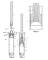
- Figure 2 illustrates a cross-sectional view of a plunger 33, a vial cap 54, and a sample vial 44 where vial cap 54 and plunger 33 are in an unengaged state.
- Plunger 33 is configured to bind to the vial cap 54.
- the vial cap 54 is configured to provide a seal at a side wall of the vial cap 54.
- Plunger 33 and the vial cap 54 together can be configured to have a piston cylinder mechanism with the sample vial 44 to dispense the liquid sample.
- a similar sample filtering apparatus is described US Patent No. 4,644,807 and US Pre-Grant Publication No. 20100224012, which are hereby incorporated by reference herein; however, the filter in this reference was used to remove particulates and/or reduce evaporation.
- vial cap 54 includes a cap body 202, an inlet portion 204, and an outlet portion 206.
- Cap body 202 includes a liquid sample passageway 208.
- Cap body 202 has an outer periphery configured to have a slidable gas and liquid seal with a side wall of sample vial 44.
- Inlet portion 204 is configured to receive a pressurized liquid sample from sample vial 44 where the liquid sample flows into liquid sample passageway 208.
- Vial cap 54 is configured to cap the open ended portion of the sample vial 44. Further, the vial cap 54 is also configured to be slidingly engaged with and to seal the side wall of the sample vial 44.
- the vial cap 54 has a generally concave portion that cooperatively mates with a generally convex lowermost portion of the sample vial 44.
- Inlet portion can include a counterbore section 210 for holding a filter plug described herein.
- Counterbore section 210 is a cylindrical hole adjacent to outlet portion 206.
- the diameter of counterbore section 210 is greater than outlet portion 206.
- the diameter of counterbore section 210 is sized to form a friction fit to hold a cylindrically shaped filter plug, as illustrated in Figure 4 .
- the filter plug can be mounted to the counterbore section with other types of fasteners.
- Outlet portion 206 is configured to output the liquid sample from liquid sample passageway 208 that has passed through filter plug 42.
- Outlet portion 206 includes a plunger section 70 configured to receive a downward force into sample vial 44 to pressurize the liquid sample within sample vial 44.
- Plunger section 70 includes a socket configured to receive a plunger 33.
- Plunger 33 can have a geometric shape proximate to a tip 68 that mates with the socket of plunger section 70 to form a fluid tight seal, as illustrated in Figures 2 to 4 .
- Plunger 33 is configured to apply a downward force to vial cap 54 and transfer the liquid sample through a hollow portion of plunger 33
- the vial cap 54 does not begin to move until tip 68 of the plunger is fully seated in a plunger portion 70 (best shown in FIG. 3 ).
- any air trapped in the sample vial 44 above the sample is discharged first.
- the sample vial and vial cap are configured to reduce "dead space" in the sample vial.
- the bottom of the exemplary vial has a shape corresponding to the cap such that substantially all of the fluid is displaced from the vial when the cap contacts the bottom.
- Sample vial 44 and vial cap 54 are configured such that when the plunger 33 is fully deployed causing the vial cap 54 to remain in the lowest displacement position in the sample vial 44.
- the needle presses the vial cap 54 into the sample vial 44 but is withdrawn from the sample vial 44 without the vial cap 54.
- the vial cap remains in the sample vial with the sample pressurized below the cap.
- the vial includes a bottom portion configured to fit tightly with vial cap 54. When plunger is retracted, the vial cap can be held in the bottom portion of the vial due to the tight fit and the plunger separates from the vial cap. After displacing the liquid sample through the filter plug, the vial cap along with the filter plug can be disposed as waste and not re-used.
- Plunger 33 can also be referred to as a sample delivery needle or plunger needle and has a hollow cylindrical rod shaped structure. At one end of plunger 33, there is a needle tip 68. The other opposing end of plunger 33 can be used to transfer the liquid sample 46 to an analytical instrument.
- the vial cap will describe a method of using a vial cap to filter out and remove matrix components from a sample.
- An analyst will often have a large number of sample vials containing samples that need to be analyzed. However, before beginning the analysis testing, a sample pre-treatment may need to be performed to remove matrix components that can interfere with the analysis. Adding a matrix binding agent to the sample vial, mixing the sample vial, and filtering the matrix binding agent from the sample is a manual process that is time consuming and laborious.
- the matrix component binding filter plug can be used as a filter that is incorporated into the vial cap.
- the sample vial and vial cap are configured so that liquid flows through the vial cap and the filter at a relatively low pressure while at the same time efficiently binding a substantial portion of the matrix components.
- the pressure range for filtering sample may range from about 10 pounds per square inch to about 100 pounds per square inch.
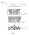
- FIG. 1 is a flow chart illustrating a method 100 of removing a matrix component from a liquid sample using a vial cap containing one of the matrix component binding filter plugs described herein.
- a liquid sample is added to a sample vial.
- a vial cap is pushed through an inlet opening of the sample vial towards the bottom wall to pressurize the liquid sample within the sample vial, as shown in a step 104.
- the liquid sample is displaced into the inlet portion, through the filter plug, and out of the outlet portion, where the filter plug includes a polyethylene resin and a matrix component binding material (e.g., ion exchange material or a reversed-phase material), as shown in a step 106.
- a matrix component binding material e.g., ion exchange material or a reversed-phase material
- a portion of the ions is removed from the liquid sample with the filter plug, as shown in a step 108.
- about 50% or more of the matrix components can be removed from the liquid sample with a filter plug.
- the sample can be subsequently analyzed with analytical instrumentation.
- the liquid sample 46 can be loaded onto a sample loop of an injection valve.
- liquid sample from the sample loop can be injected into a chromatographic separation device. At least one analyte from the liquid sample can be separated from matrix components in the chromatographic separation device and the analyte can be detected at a detector.
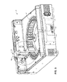
- Figure 5 is a partial perspective view of an autosampler 30 suitable for dispensing liquid samples from a plurality of sample vials and for use with filter plugs described herein.
- Autosampler 30 is typically used when a large number of samples need to processed in an automated manner.
- a plurality of sample vials can be loaded on autosampler 30 in an array or carousel format.
- Figure 5 illustrates a carousel of sample vial sockets 47 configured to hold a plurality of sample vials.
- a fluid delivery assembly 32 is configured to deploy and retract the plunger needle for one sample vial at a time as shown in a dotted circle 1 B of Figure 5 .
- Autosampler 30 also includes a control system 74 that has a microprocessor 75 and a memory 77. Examples of commercially available autosamplers are the AS-DV, AS40, and ASM from Thermo Fisher Scientific.
- This Example illustrates the removal of divalent cations using a cation-exchange filter plug.
- a cylindrical filter plug of blended high density polyethylene (HDPE) and approximately 10 mg fully sulfonated, 16% crosslinked styrenesulfonate, sodium-form resin with a particle diameter of 35 ⁇ m was inserted into the counterbore portion of a vial cap.
- the cylindrical filter plug had an approximate diameter of 5 mm and a length of about 10 mm.
- the assembled vial cap with the cation exchange filter plug was sonicated in deionized water for 5 minutes.
- a standard sample of six cations including 0.05 mg/L lithium, 0.2 mg/L sodium, 0.4 mg/L ammonium, 0.2 mg/L potassium, 0.2 mg/L magnesium and 1 mg/L calcium was loaded into a 5 mL sample vial.
- the assembled vial cap was inserted into the filled sample vial.
- Five milliliters of a sample (see Table 1) was pushed up through the filter plug in the vial cap and directed to a sample loop of an ion chromatograph for analysis using cation exchange chromatography.
- An eluent of 20 mM methanesulfonic acid was flowed at 0.5 mL/min through a cation exchange analytical column (part no.
- Table 1 shows the results from a series of samples pretreated with the filter plug of Example 1 and analyzed using cation exchange chromatography.
- Sample Description Area Sodium % Removed Area, Calcium % Removed ⁇ S*min ⁇ S*min 1 6 Cation Standard with no solid phase extraction 0.039 - 0.18 - 2 Water Flowed Through Filter Plug of Ex. 1 0.108 - 0.004 - 3 6 Cation Standard Flowed Through Filter Plug of Ex. 1 1.34 * 0.007 61 *Sodium increase due to displacement from the cation exchange resin by calcium
- This Example illustrates the use of an ion-pairing reagent-functionalized reversed phase filter cap to remove cations from a sample.
- a cylindrical plug comprising blended high density polyethylene (HDPE) and 10 mg of 55% divinylbenzene resin with a particle diameter of 35 ⁇ m was inserted into the counterbore portion of a vial cap.
- the cylindrical filter plug had an approximate diameter of 5 mm and a length of about 10 mm.
- the assembled vial cap with the cation exchange filter plug was placed on a vacuum station and 2 mL of methanol was pushed up through the filter plug.
- the assembled vial cap was sequentially flushed with a series of liquids, which 2 mL deionized water, 2 mL of 100 mM hexanesulfonic acid (HSA), and another aliquot of deionized water.
- a series of liquids which 2 mL deionized water, 2 mL of 100 mM hexanesulfonic acid (HSA), and another aliquot of deionized water.
- a standard sample of four cations including 5 ppb lithium, 20 ppb sodium, 20ppb magnesium and 100 ppb calcium was loaded into a sample vial.
- the assembled vial cap was inserted into the filled sample vial.
- Two milliliters of a sample (see Table 2) was pushed up through the filter plug in the vial cap and directed to the ion chromatograph for cation exchange analysis.
- the cation exchange chromatography system conditions were similar to Example 1.
- Table 2 shows the results from a series of samples pretreated with the filter plug of Example 2 and analyzed using cation exchange chromatography.
- Sample Description Area Sodium % Area, Magnesium % Removed Area, Calcium % Removed ⁇ S*min Removed ⁇ S*min ⁇ S*min 1 4 Cation Standard with no solid phase extraction 0.01 - 0.028 - 0.007 - 2
- Deionized water blank na - - - - - - 3 4 Cation Standard Flowed Through Filter Plug of Ex. 2 without HSA 0.01 0 0.029 0 0.007 0 4 4 Cation Standard Flowed Through Filter Plug of Ex. 2 with HSA 0.01 0 0.011 62 0.002 71
- This Example illustrates the use of an anion exchange filter plug prepared with latex particles to remove anions from a sample.
- a cylindrical filter plug of blended high density polyethylene (HDPE) and approximately 10 mg fully sulfonated, 16% crosslinked styrenesulfonate, sodium-form resin with a particle diameter of 35 ⁇ m was inserted into the counterbore portion of a vial cap as described in Example 1.
- the cylindrical filter plug had an approximate diameter of 5 mm and a length of about 10 mm.
- a standard sample of six anions including 0.02 mg/L fluoride, 0.03 mg/L chloride, 0.1 mg/L nitrate, 0.15 mg/L sulfate, 0.15 mg/L phosphate, and 0.01% acetic acid was loaded into a 5 mL sample vial.
- the assembled vial cap was inserted into the filled sample vial.
- Five milliliters of sample (see Table 3) was pushed through the filter plug in the vial cap and directed to the ion chromatograph for an ion exchange analysis.
- An eluent of 40 mM potassium hydroxide flowed at 0.3 mL/minute through an anion exchange analytical column (part no. AS15, 150 x 3 mm I.D.) and an electrolytic suppressor (part no. ASRS 2-mm) both supplied by Thermo Fisher Scientific.
- An electrical conductivity detector cell was used to measure the anions.
- Table 3 shows the results from a series of samples pretreated with the filter plug of Example 3 and analyzed using anion exchange chromatography.
- Sample Description Area Sulfate ⁇ S*min % Removed Area, Phosphate ⁇ S*min % Removed 1 6 Anion Standard With No Solid Phase Extraction 0.15 - 0.03 - 2 Water Flowed Through Filter Plug of Ex. 3 0.005 - 0 - 3 6 Anion Standard pH 5 Flowed Through Filter Plug of Ex. 3 0.06 60 0 100
- This Example illustrates the use of a reversed-phase filter plug prepared with divinylbenzene resin to remove hydrophobic material such as sodium lauryl sulfate (SLS) from an aqueous sample.
- a cylindrical plug from Example 2 was used in a vial cap for this example.
- the assembled vial cap was inserted into the filled sample vial.
- Five milliliters of a 100 mg/L sodium lauryl sulfate sample was pushed up through the filter plug in the vial cap and directed to the liquid chromatograph for surfactant analysis.
- An eluent of 75% acetonitrile and 25% of 100 mM ammonium acetate at pH 5.4 was flowed at 0.25 mL/min through a reversed phase analytical column (part no. Acclaim Surfactant, 150 x 2-mm I.D., commercially available from Thermo Fisher Scientific) followed by detection using a mass spectrometer (part no. MSQ Plus, commercially available from Thermo Fisher Scientific).
- the resulting chromatography peaks were integrated using CHROMELEONTM chromatography data system software (version 6.8, commercially available from Thermo Fisher Scientific).
- the amount of SLS injected into the analytical system was the amount of SLS that was not captured by the filter plug in the vial cap. This amount corresponded to a removal of 98% of the SLS from the sample.
- the removal of the matrix components in this Example demonstrates that analysis of common anions such as chloride and sulfate can be performed.
Landscapes
- Physics & Mathematics (AREA)
- Health & Medical Sciences (AREA)
- Life Sciences & Earth Sciences (AREA)
- Chemical & Material Sciences (AREA)
- Analytical Chemistry (AREA)
- Biochemistry (AREA)
- General Health & Medical Sciences (AREA)
- General Physics & Mathematics (AREA)
- Immunology (AREA)
- Pathology (AREA)
- Engineering & Computer Science (AREA)
- Mechanical Engineering (AREA)
- Treatment Of Liquids With Adsorbents In General (AREA)
- Sampling And Sample Adjustment (AREA)
Applications Claiming Priority (1)
| Application Number | Priority Date | Filing Date | Title |
|---|---|---|---|
| US14/586,339 US10495614B2 (en) | 2014-12-30 | 2014-12-30 | Vial cap and method for removing matrix components from a liquid sample |
Publications (2)
| Publication Number | Publication Date |
|---|---|
| EP3040721A1 true EP3040721A1 (fr) | 2016-07-06 |
| EP3040721B1 EP3040721B1 (fr) | 2020-07-29 |
Family
ID=55129430
Family Applications (1)
| Application Number | Title | Priority Date | Filing Date |
|---|---|---|---|
| EP15201962.6A Active EP3040721B1 (fr) | 2014-12-30 | 2015-12-22 | Bouchon de flacon et procédé permettant d'éliminer des composants de la matrice dans un échantillon liquide |
Country Status (3)
| Country | Link |
|---|---|
| US (3) | US10495614B2 (fr) |
| EP (1) | EP3040721B1 (fr) |
| CN (1) | CN105730859B (fr) |
Cited By (7)
| Publication number | Priority date | Publication date | Assignee | Title |
|---|---|---|---|---|
| WO2018013946A1 (fr) * | 2016-07-15 | 2018-01-18 | Entech Instruments Inc. | Analyse de condensat d'haleine et de salive par rinçage oral |
| WO2018128840A1 (fr) * | 2017-01-03 | 2018-07-12 | Illumina, Inc. | Tube d'échantillon à tête de piston de mélange intégrée |
| US10502664B2 (en) | 2016-03-08 | 2019-12-10 | Entech Instruments Inc. | Vacuum-assisted sample extraction device and method |
| US10849600B2 (en) | 2016-03-08 | 2020-12-01 | Entech Instruments Inc. | Breath condensate and saliva analysis using oral rinse |
| US11896366B2 (en) | 2018-03-06 | 2024-02-13 | Entech Instruments Inc. | Ventilator-coupled sampling device and method |
| US12158454B2 (en) | 2018-07-31 | 2024-12-03 | Entech Instruments Inc. | Hybrid capillary/packed trap and method of use |
| US12560581B2 (en) | 2020-08-11 | 2026-02-24 | Entech Instruments Inc. | System and method of matrix accelerated vacuum-assisted sorbent extraction for improved sample preparation prior to GCMS analysis |
Families Citing this family (12)
| Publication number | Priority date | Publication date | Assignee | Title |
|---|---|---|---|---|
| US10495614B2 (en) * | 2014-12-30 | 2019-12-03 | Dionex Corporation | Vial cap and method for removing matrix components from a liquid sample |
| JP6961618B2 (ja) * | 2016-12-13 | 2021-11-05 | オルガノ株式会社 | イオン交換体充填カートリッジ及び金属除去カラム |
| WO2019099039A1 (fr) * | 2017-11-17 | 2019-05-23 | Bio-Rad Laboratories, Inc. | Bouchon de chromatographie |
| CN108072718A (zh) * | 2018-02-09 | 2018-05-25 | 西北大学 | 一种高效液相色谱测定甲基丙烯酰氧乙基三甲基氯化铵含量的方法 |
| CN108452552B (zh) * | 2018-04-02 | 2023-08-04 | 中国烟草总公司郑州烟草研究院 | 固相微萃取装置及其固相微萃取前处理组件 |
| WO2021042070A1 (fr) * | 2019-08-30 | 2021-03-04 | Protifi, Llc | Procédé de préparation d'échantillons multiomiques simultanés sans détergent au moyen d'une nouvelle conception de vésicule innovante |
| WO2021100006A1 (fr) * | 2019-11-22 | 2021-05-27 | Psyllaki Eleftheria | Procédés et fermetures de flacons pour une microextraction dans l'espace libre sous vide |
| GB2592430B (en) * | 2020-02-28 | 2022-12-21 | Agilent Technologies Inc | Sample injector with sample fluid filtering |
| AU2021235877A1 (en) | 2020-03-09 | 2022-09-22 | Idexx Laboratories, Inc. | Matrix and associated sample or mixing cup used for removing components of a liquid sample |
| CA3168170A1 (fr) | 2020-03-09 | 2021-09-16 | Pamela Ann Cacavas | Methode d'elimination de constituants interferents d'un echantillon liquide avant sa distribution sur une lame de test de reactif chimique |
| EP4308900A1 (fr) | 2021-03-16 | 2024-01-24 | The USA, as represented by The Secretary, Department of Health and Human Services | Procédés et systèmes d'extraction en phase solide |
| CN113341035A (zh) * | 2021-07-29 | 2021-09-03 | 湖南沁森高科新材料有限公司 | 一种樟脑磺酸和十二烷基硫酸钠的检测方法 |
Citations (6)
| Publication number | Priority date | Publication date | Assignee | Title |
|---|---|---|---|---|
| US4644807A (en) | 1985-02-21 | 1987-02-24 | Dionex Corporation | Fluid sample delivery apparatus |
| EP0385587A1 (fr) * | 1989-02-27 | 1990-09-05 | Dionex Corporation | Composition échangeuse d'ions utilisant une résine pour l'attachement au dispersant, et méthode pour sa formation |
| US5567309A (en) * | 1994-02-14 | 1996-10-22 | Alcott Chromatography, Inc. | Self-filtration cap |
| JP3015870B2 (ja) * | 1997-04-30 | 2000-03-06 | 農林水産省農業研究センター所長 | 試料調製方法および装置 |
| WO2004007081A1 (fr) * | 2002-07-15 | 2004-01-22 | Phynexus, Inc. | Dispositifs de colonnes d'extraction a faible volume mort |
| US20100224012A1 (en) | 2009-03-06 | 2010-09-09 | Dionex Corporation | Fluid sample delivery system and method |
Family Cites Families (29)
| Publication number | Priority date | Publication date | Assignee | Title |
|---|---|---|---|---|
| US3024207A (en) | 1958-04-10 | 1962-03-06 | Rohm & Haas | Ion-exchange products and methods for making and suing them |
| NL245047A (fr) | 1958-11-06 | |||
| US3481477A (en) | 1965-03-02 | 1969-12-02 | Andrew F Farr | Apparatus for filtering out clear liquid from suspended solids |
| US4263407A (en) | 1978-07-24 | 1981-04-21 | Rohm And Haas Company | Polymeric adsorbents from macroreticular polymer beads |
| US5037859A (en) | 1989-06-20 | 1991-08-06 | The United States Of America As Represented By The United States Department Of Energy | Composite foams |
| JPH07204429A (ja) | 1993-12-21 | 1995-08-08 | Porex Technol Corp | フィルターとイオン交換材料との結合製品及び該結合製品を使用して流体を処理するための方法 |
| WO1995031485A1 (fr) | 1994-05-15 | 1995-11-23 | Pharmacia Biotech Ab | Procede de preparation de particules et particules preparees d'apres ce procede |
| US5583162A (en) | 1994-06-06 | 1996-12-10 | Biopore Corporation | Polymeric microbeads and method of preparation |
| SE9504205D0 (sv) | 1995-11-24 | 1995-11-24 | Pharmacia Biotech Ab | A chromatographic separation method and device |
| US5864957A (en) | 1997-12-29 | 1999-02-02 | Small; Bernard | Universal sight tool |
| SE512222C2 (sv) | 1998-06-29 | 2000-02-14 | Johan Sterte | Förfarande för framställning av makrostrukturer av mikroporösa material |
| US6573305B1 (en) | 1999-09-17 | 2003-06-03 | 3M Innovative Properties Company | Foams made by photopolymerization of emulsions |
| EP1232009B1 (fr) | 1999-11-23 | 2005-05-04 | Porex Corporation | Materiaux echangeurs d'ions immobilises et leurs procedes de fabrication |
| MXPA00012167A (es) | 1999-12-24 | 2002-08-06 | Bayer Ag | Procedimiento para la obtencion de polimeros en perlas, reticulados, monodispersados. |
| EP1339779A2 (fr) | 2000-11-07 | 2003-09-03 | The Procter & Gamble Company | Composites de mousse fibreux derives d'emulsions a phase interne elevee |
| WO2002083770A1 (fr) | 2001-04-13 | 2002-10-24 | Organo Corporation | Echangeur d'ions poreux composite et son procede de fabrication, module de desionisation utilisant cet echangeur d'ions et dispositif de production d'eau desionisee |
| US6841580B2 (en) | 2001-12-21 | 2005-01-11 | Organo Corporation | Organic porous material, process for manufacturing the same, and organic porous ion exchanger |
| GB0215832D0 (en) | 2002-07-09 | 2002-08-14 | Akay Galip | Preparation of composite high internal phase emulsion polymerised microporous polymers and their applications |
| JP4011440B2 (ja) | 2002-08-28 | 2007-11-21 | オルガノ株式会社 | イオン吸着モジュール及び水処理方法 |
| US6750261B1 (en) | 2003-04-08 | 2004-06-15 | 3M Innovative Properties Company | High internal phase emulsion foams containing polyelectrolytes |
| FR2862976B1 (fr) | 2003-11-28 | 2006-01-13 | Commissariat Energie Atomique | Mousses polymeres de tres basse densite et leur procede de fabrication |
| FR2864092B1 (fr) | 2003-12-19 | 2006-02-03 | Commissariat Energie Atomique | Mousses polymeres a cellules ouvertes de tres faible diametre et leur procede de fabrication |
| US7303671B2 (en) | 2004-02-11 | 2007-12-04 | Dionex Corporation | Ion exchange particle-bound flow-through porous monolith |
| JP5019471B2 (ja) | 2007-08-10 | 2012-09-05 | オルガノ株式会社 | モノリス状有機多孔質体、モノリス状有機多孔質イオン交換体、それらの製造方法及びケミカルフィルター |
| DE102008006874A1 (de) | 2008-01-31 | 2009-08-06 | Merck Patent Gmbh | Monolithische Polymaterialien zur Gasspeicherung |
| WO2010120977A1 (fr) | 2009-04-16 | 2010-10-21 | Porex Corporation | Matériaux frittés poreux meulés et applications associées |
| JP5403467B2 (ja) | 2010-04-26 | 2014-01-29 | 独立行政法人日本原子力研究開発機構 | 微量金属捕集用液体濾過フィルタ |
| EP2833984A4 (fr) | 2012-04-05 | 2016-01-06 | 3M Innovative Properties Co | Milieux d'échange ionique composites pour des systèmes de filtration liquide |
| US10495614B2 (en) * | 2014-12-30 | 2019-12-03 | Dionex Corporation | Vial cap and method for removing matrix components from a liquid sample |
-
2014
- 2014-12-30 US US14/586,339 patent/US10495614B2/en active Active
-
2015
- 2015-12-22 EP EP15201962.6A patent/EP3040721B1/fr active Active
- 2015-12-28 CN CN201511005332.XA patent/CN105730859B/zh active Active
-
2019
- 2019-11-07 US US16/677,089 patent/US10921298B2/en active Active
-
2021
- 2021-02-12 US US17/174,716 patent/US12038422B2/en active Active
Patent Citations (7)
| Publication number | Priority date | Publication date | Assignee | Title |
|---|---|---|---|---|
| US4644807A (en) | 1985-02-21 | 1987-02-24 | Dionex Corporation | Fluid sample delivery apparatus |
| EP0385587A1 (fr) * | 1989-02-27 | 1990-09-05 | Dionex Corporation | Composition échangeuse d'ions utilisant une résine pour l'attachement au dispersant, et méthode pour sa formation |
| US5324752A (en) | 1989-02-27 | 1994-06-28 | Dionex Corporation | Ion-exchange composition employing resin attachment to dispersant and method for forming the same |
| US5567309A (en) * | 1994-02-14 | 1996-10-22 | Alcott Chromatography, Inc. | Self-filtration cap |
| JP3015870B2 (ja) * | 1997-04-30 | 2000-03-06 | 農林水産省農業研究センター所長 | 試料調製方法および装置 |
| WO2004007081A1 (fr) * | 2002-07-15 | 2004-01-22 | Phynexus, Inc. | Dispositifs de colonnes d'extraction a faible volume mort |
| US20100224012A1 (en) | 2009-03-06 | 2010-09-09 | Dionex Corporation | Fluid sample delivery system and method |
Cited By (9)
| Publication number | Priority date | Publication date | Assignee | Title |
|---|---|---|---|---|
| US10502664B2 (en) | 2016-03-08 | 2019-12-10 | Entech Instruments Inc. | Vacuum-assisted sample extraction device and method |
| US10849600B2 (en) | 2016-03-08 | 2020-12-01 | Entech Instruments Inc. | Breath condensate and saliva analysis using oral rinse |
| WO2018013946A1 (fr) * | 2016-07-15 | 2018-01-18 | Entech Instruments Inc. | Analyse de condensat d'haleine et de salive par rinçage oral |
| WO2018128840A1 (fr) * | 2017-01-03 | 2018-07-12 | Illumina, Inc. | Tube d'échantillon à tête de piston de mélange intégrée |
| RU2711190C1 (ru) * | 2017-01-03 | 2020-01-15 | Иллюмина, Инк. | Пробоотборная трубка с встроенной смесительной поршневой головкой |
| US10537892B2 (en) | 2017-01-03 | 2020-01-21 | Illumina, Inc. | Sample tube with integrated mixing plunger head |
| US11896366B2 (en) | 2018-03-06 | 2024-02-13 | Entech Instruments Inc. | Ventilator-coupled sampling device and method |
| US12158454B2 (en) | 2018-07-31 | 2024-12-03 | Entech Instruments Inc. | Hybrid capillary/packed trap and method of use |
| US12560581B2 (en) | 2020-08-11 | 2026-02-24 | Entech Instruments Inc. | System and method of matrix accelerated vacuum-assisted sorbent extraction for improved sample preparation prior to GCMS analysis |
Also Published As
| Publication number | Publication date |
|---|---|
| US10495614B2 (en) | 2019-12-03 |
| US20200072802A1 (en) | 2020-03-05 |
| US20210164949A1 (en) | 2021-06-03 |
| US20160187306A1 (en) | 2016-06-30 |
| CN105730859A (zh) | 2016-07-06 |
| US10921298B2 (en) | 2021-02-16 |
| US12038422B2 (en) | 2024-07-16 |
| CN105730859B (zh) | 2018-07-03 |
| EP3040721B1 (fr) | 2020-07-29 |
Similar Documents
| Publication | Publication Date | Title |
|---|---|---|
| US12038422B2 (en) | Vial cap and method for removing matrix components from a liquid sample | |
| Lanza et al. | The application of molecular imprinting technology to solid phase extraction | |
| Turiel et al. | Molecularly imprinted polymers | |
| Matsui et al. | Solid-phase extraction of a triazine herbicide using a molecularly imprinted synthetic receptor | |
| Poole | New trends in solid-phase extraction | |
| Kataoka | New trends in sample preparation for clinical and pharmaceutical analysis | |
| Du et al. | A novel restricted access material combined to molecularly imprinted polymers for selective solid-phase extraction and high performance liquid chromatography determination of 2-methoxyestradiol in plasma samples | |
| Li et al. | Solid-phase extraction (SPE) techniques for sample preparation in clinical and pharmaceutical analysis: a brief overview | |
| Lingeman et al. | Particle-loaded membranes for sample concentration and/or clean-up in bioanalysis | |
| US10076756B2 (en) | Ion exchange foams to remove ions from samples | |
| Hu et al. | An amobarbital molecularly imprinted microsphere for selective solid-phase extraction of phenobarbital from human urine and medicines and their determination by high-performance liquid chromatography | |
| US9702856B2 (en) | System and method for rapid analysis of polymer additives | |
| Yan et al. | Screening, recognition and quantitation of salbutamol residues in ham sausages by molecularly imprinted solid phase extraction coupled with high-performance liquid chromatography–ultraviolet detection | |
| Nechvátalová et al. | Current trends in the development of polymer‐based monolithic stationary phases | |
| US20220097024A1 (en) | Method for preparing monolithic coated surfaces | |
| de Carvalho Abrão et al. | Restricted access materials for sample preparation | |
| Campíns‐Falcó et al. | Solid‐phase extraction and clean‐up procedures in pharmaceutical analysis | |
| Guzzella et al. | Synthesis and characterization of a propazine imprinted polymer for the extraction of triazines herbicides | |
| Dolgonosov et al. | Composites with a porous bipolar surface for ion chromatography | |
| Alkarimi et al. | Proteins Pre-Concentration Using Glycidyl Methacrylate-co-Stearyl Methacrylate-co-Ethylene Glycol Dimethacrylate Monolith | |
| Zhu et al. | Simultaneous determination of caffeine and theophylline in human plasma with a weak cation monolithic SPE‐column | |
| JP2006349356A (ja) | 分離処理用の充填材の製造方法 | |
| Davankov et al. | Hypercrosslinked polystyrene as column packing material in HPLC | |
| CN207923795U (zh) | 一种用于毒素检测的固相萃取串联柱 | |
| Papadoyannis et al. | Sample Preparation Prior to HPLC |
Legal Events
| Date | Code | Title | Description |
|---|---|---|---|
| PUAI | Public reference made under article 153(3) epc to a published international application that has entered the european phase |
Free format text: ORIGINAL CODE: 0009012 |
|
| AK | Designated contracting states |
Kind code of ref document: A1 Designated state(s): AL AT BE BG CH CY CZ DE DK EE ES FI FR GB GR HR HU IE IS IT LI LT LU LV MC MK MT NL NO PL PT RO RS SE SI SK SM TR |
|
| AX | Request for extension of the european patent |
Extension state: BA ME |
|
| STAA | Information on the status of an ep patent application or granted ep patent |
Free format text: STATUS: REQUEST FOR EXAMINATION WAS MADE |
|
| 17P | Request for examination filed |
Effective date: 20170103 |
|
| RBV | Designated contracting states (corrected) |
Designated state(s): AL AT BE BG CH CY CZ DE DK EE ES FI FR GB GR HR HU IE IS IT LI LT LU LV MC MK MT NL NO PL PT RO RS SE SI SK SM TR |
|
| STAA | Information on the status of an ep patent application or granted ep patent |
Free format text: STATUS: EXAMINATION IS IN PROGRESS |
|
| 17Q | First examination report despatched |
Effective date: 20181128 |
|
| GRAP | Despatch of communication of intention to grant a patent |
Free format text: ORIGINAL CODE: EPIDOSNIGR1 |
|
| STAA | Information on the status of an ep patent application or granted ep patent |
Free format text: STATUS: GRANT OF PATENT IS INTENDED |
|
| RIC1 | Information provided on ipc code assigned before grant |
Ipc: G01N 30/24 20060101ALN20200115BHEP Ipc: B01L 3/00 20060101ALI20200115BHEP Ipc: G01N 30/96 20060101ALN20200115BHEP Ipc: G01N 30/14 20060101AFI20200115BHEP Ipc: G01N 30/00 20060101ALN20200115BHEP |
|
| RIC1 | Information provided on ipc code assigned before grant |
Ipc: G01N 30/24 20060101ALN20200127BHEP Ipc: B01L 3/00 20060101ALI20200127BHEP Ipc: G01N 30/96 20060101ALN20200127BHEP Ipc: G01N 30/14 20060101AFI20200127BHEP Ipc: G01N 30/00 20060101ALN20200127BHEP |
|
| INTG | Intention to grant announced |
Effective date: 20200219 |
|
| GRAS | Grant fee paid |
Free format text: ORIGINAL CODE: EPIDOSNIGR3 |
|
| GRAA | (expected) grant |
Free format text: ORIGINAL CODE: 0009210 |
|
| STAA | Information on the status of an ep patent application or granted ep patent |
Free format text: STATUS: THE PATENT HAS BEEN GRANTED |
|
| AK | Designated contracting states |
Kind code of ref document: B1 Designated state(s): AL AT BE BG CH CY CZ DE DK EE ES FI FR GB GR HR HU IE IS IT LI LT LU LV MC MK MT NL NO PL PT RO RS SE SI SK SM TR |
|
| REG | Reference to a national code |
Ref country code: CH Ref legal event code: EP |
|
| REG | Reference to a national code |
Ref country code: AT Ref legal event code: REF Ref document number: 1296384 Country of ref document: AT Kind code of ref document: T Effective date: 20200815 |
|
| REG | Reference to a national code |
Ref country code: IE Ref legal event code: FG4D |
|
| REG | Reference to a national code |
Ref country code: DE Ref legal event code: R096 Ref document number: 602015056447 Country of ref document: DE |
|
| REG | Reference to a national code |
Ref country code: CH Ref legal event code: NV Representative=s name: NOVAGRAAF INTERNATIONAL SA, CH |
|
| REG | Reference to a national code |
Ref country code: DE Ref legal event code: R082 Ref document number: 602015056447 Country of ref document: DE Representative=s name: BOULT WADE TENNANT LLP, DE |
|
| REG | Reference to a national code |
Ref country code: LT Ref legal event code: MG4D |
|
| REG | Reference to a national code |
Ref country code: NL Ref legal event code: MP Effective date: 20200729 |
|
| REG | Reference to a national code |
Ref country code: AT Ref legal event code: MK05 Ref document number: 1296384 Country of ref document: AT Kind code of ref document: T Effective date: 20200729 |
|
| PG25 | Lapsed in a contracting state [announced via postgrant information from national office to epo] |
Ref country code: GR Free format text: LAPSE BECAUSE OF FAILURE TO SUBMIT A TRANSLATION OF THE DESCRIPTION OR TO PAY THE FEE WITHIN THE PRESCRIBED TIME-LIMIT Effective date: 20201030 Ref country code: LT Free format text: LAPSE BECAUSE OF FAILURE TO SUBMIT A TRANSLATION OF THE DESCRIPTION OR TO PAY THE FEE WITHIN THE PRESCRIBED TIME-LIMIT Effective date: 20200729 Ref country code: ES Free format text: LAPSE BECAUSE OF FAILURE TO SUBMIT A TRANSLATION OF THE DESCRIPTION OR TO PAY THE FEE WITHIN THE PRESCRIBED TIME-LIMIT Effective date: 20200729 Ref country code: PT Free format text: LAPSE BECAUSE OF FAILURE TO SUBMIT A TRANSLATION OF THE DESCRIPTION OR TO PAY THE FEE WITHIN THE PRESCRIBED TIME-LIMIT Effective date: 20201130 Ref country code: FI Free format text: LAPSE BECAUSE OF FAILURE TO SUBMIT A TRANSLATION OF THE DESCRIPTION OR TO PAY THE FEE WITHIN THE PRESCRIBED TIME-LIMIT Effective date: 20200729 Ref country code: HR Free format text: LAPSE BECAUSE OF FAILURE TO SUBMIT A TRANSLATION OF THE DESCRIPTION OR TO PAY THE FEE WITHIN THE PRESCRIBED TIME-LIMIT Effective date: 20200729 Ref country code: BG Free format text: LAPSE BECAUSE OF FAILURE TO SUBMIT A TRANSLATION OF THE DESCRIPTION OR TO PAY THE FEE WITHIN THE PRESCRIBED TIME-LIMIT Effective date: 20201029 Ref country code: NO Free format text: LAPSE BECAUSE OF FAILURE TO SUBMIT A TRANSLATION OF THE DESCRIPTION OR TO PAY THE FEE WITHIN THE PRESCRIBED TIME-LIMIT Effective date: 20201029 Ref country code: AT Free format text: LAPSE BECAUSE OF FAILURE TO SUBMIT A TRANSLATION OF THE DESCRIPTION OR TO PAY THE FEE WITHIN THE PRESCRIBED TIME-LIMIT Effective date: 20200729 Ref country code: SE Free format text: LAPSE BECAUSE OF FAILURE TO SUBMIT A TRANSLATION OF THE DESCRIPTION OR TO PAY THE FEE WITHIN THE PRESCRIBED TIME-LIMIT Effective date: 20200729 |
|
| PG25 | Lapsed in a contracting state [announced via postgrant information from national office to epo] |
Ref country code: IS Free format text: LAPSE BECAUSE OF FAILURE TO SUBMIT A TRANSLATION OF THE DESCRIPTION OR TO PAY THE FEE WITHIN THE PRESCRIBED TIME-LIMIT Effective date: 20201129 Ref country code: RS Free format text: LAPSE BECAUSE OF FAILURE TO SUBMIT A TRANSLATION OF THE DESCRIPTION OR TO PAY THE FEE WITHIN THE PRESCRIBED TIME-LIMIT Effective date: 20200729 Ref country code: PL Free format text: LAPSE BECAUSE OF FAILURE TO SUBMIT A TRANSLATION OF THE DESCRIPTION OR TO PAY THE FEE WITHIN THE PRESCRIBED TIME-LIMIT Effective date: 20200729 Ref country code: LV Free format text: LAPSE BECAUSE OF FAILURE TO SUBMIT A TRANSLATION OF THE DESCRIPTION OR TO PAY THE FEE WITHIN THE PRESCRIBED TIME-LIMIT Effective date: 20200729 |
|
| PG25 | Lapsed in a contracting state [announced via postgrant information from national office to epo] |
Ref country code: NL Free format text: LAPSE BECAUSE OF FAILURE TO SUBMIT A TRANSLATION OF THE DESCRIPTION OR TO PAY THE FEE WITHIN THE PRESCRIBED TIME-LIMIT Effective date: 20200729 |
|
| PG25 | Lapsed in a contracting state [announced via postgrant information from national office to epo] |
Ref country code: SM Free format text: LAPSE BECAUSE OF FAILURE TO SUBMIT A TRANSLATION OF THE DESCRIPTION OR TO PAY THE FEE WITHIN THE PRESCRIBED TIME-LIMIT Effective date: 20200729 Ref country code: RO Free format text: LAPSE BECAUSE OF FAILURE TO SUBMIT A TRANSLATION OF THE DESCRIPTION OR TO PAY THE FEE WITHIN THE PRESCRIBED TIME-LIMIT Effective date: 20200729 Ref country code: EE Free format text: LAPSE BECAUSE OF FAILURE TO SUBMIT A TRANSLATION OF THE DESCRIPTION OR TO PAY THE FEE WITHIN THE PRESCRIBED TIME-LIMIT Effective date: 20200729 Ref country code: CZ Free format text: LAPSE BECAUSE OF FAILURE TO SUBMIT A TRANSLATION OF THE DESCRIPTION OR TO PAY THE FEE WITHIN THE PRESCRIBED TIME-LIMIT Effective date: 20200729 Ref country code: DK Free format text: LAPSE BECAUSE OF FAILURE TO SUBMIT A TRANSLATION OF THE DESCRIPTION OR TO PAY THE FEE WITHIN THE PRESCRIBED TIME-LIMIT Effective date: 20200729 Ref country code: IT Free format text: LAPSE BECAUSE OF FAILURE TO SUBMIT A TRANSLATION OF THE DESCRIPTION OR TO PAY THE FEE WITHIN THE PRESCRIBED TIME-LIMIT Effective date: 20200729 |
|
| REG | Reference to a national code |
Ref country code: DE Ref legal event code: R097 Ref document number: 602015056447 Country of ref document: DE |
|
| PG25 | Lapsed in a contracting state [announced via postgrant information from national office to epo] |
Ref country code: AL Free format text: LAPSE BECAUSE OF FAILURE TO SUBMIT A TRANSLATION OF THE DESCRIPTION OR TO PAY THE FEE WITHIN THE PRESCRIBED TIME-LIMIT Effective date: 20200729 |
|
| PLBE | No opposition filed within time limit |
Free format text: ORIGINAL CODE: 0009261 |
|
| STAA | Information on the status of an ep patent application or granted ep patent |
Free format text: STATUS: NO OPPOSITION FILED WITHIN TIME LIMIT |
|
| PG25 | Lapsed in a contracting state [announced via postgrant information from national office to epo] |
Ref country code: SK Free format text: LAPSE BECAUSE OF FAILURE TO SUBMIT A TRANSLATION OF THE DESCRIPTION OR TO PAY THE FEE WITHIN THE PRESCRIBED TIME-LIMIT Effective date: 20200729 |
|
| 26N | No opposition filed |
Effective date: 20210430 |
|
| PG25 | Lapsed in a contracting state [announced via postgrant information from national office to epo] |
Ref country code: SI Free format text: LAPSE BECAUSE OF FAILURE TO SUBMIT A TRANSLATION OF THE DESCRIPTION OR TO PAY THE FEE WITHIN THE PRESCRIBED TIME-LIMIT Effective date: 20200729 Ref country code: MC Free format text: LAPSE BECAUSE OF FAILURE TO SUBMIT A TRANSLATION OF THE DESCRIPTION OR TO PAY THE FEE WITHIN THE PRESCRIBED TIME-LIMIT Effective date: 20200729 |
|
| REG | Reference to a national code |
Ref country code: BE Ref legal event code: MM Effective date: 20201231 |
|
| PG25 | Lapsed in a contracting state [announced via postgrant information from national office to epo] |
Ref country code: IE Free format text: LAPSE BECAUSE OF NON-PAYMENT OF DUE FEES Effective date: 20201222 Ref country code: LU Free format text: LAPSE BECAUSE OF NON-PAYMENT OF DUE FEES Effective date: 20201222 Ref country code: FR Free format text: LAPSE BECAUSE OF NON-PAYMENT OF DUE FEES Effective date: 20201231 |
|
| PG25 | Lapsed in a contracting state [announced via postgrant information from national office to epo] |
Ref country code: TR Free format text: LAPSE BECAUSE OF FAILURE TO SUBMIT A TRANSLATION OF THE DESCRIPTION OR TO PAY THE FEE WITHIN THE PRESCRIBED TIME-LIMIT Effective date: 20200729 Ref country code: MT Free format text: LAPSE BECAUSE OF FAILURE TO SUBMIT A TRANSLATION OF THE DESCRIPTION OR TO PAY THE FEE WITHIN THE PRESCRIBED TIME-LIMIT Effective date: 20200729 Ref country code: CY Free format text: LAPSE BECAUSE OF FAILURE TO SUBMIT A TRANSLATION OF THE DESCRIPTION OR TO PAY THE FEE WITHIN THE PRESCRIBED TIME-LIMIT Effective date: 20200729 |
|
| PG25 | Lapsed in a contracting state [announced via postgrant information from national office to epo] |
Ref country code: MK Free format text: LAPSE BECAUSE OF FAILURE TO SUBMIT A TRANSLATION OF THE DESCRIPTION OR TO PAY THE FEE WITHIN THE PRESCRIBED TIME-LIMIT Effective date: 20200729 |
|
| PG25 | Lapsed in a contracting state [announced via postgrant information from national office to epo] |
Ref country code: BE Free format text: LAPSE BECAUSE OF NON-PAYMENT OF DUE FEES Effective date: 20201231 |
|
| REG | Reference to a national code |
Ref country code: CH Ref legal event code: U11 Free format text: ST27 STATUS EVENT CODE: U-0-0-U10-U11 (AS PROVIDED BY THE NATIONAL OFFICE) Effective date: 20260101 |
|
| PGFP | Annual fee paid to national office [announced via postgrant information from national office to epo] |
Ref country code: DE Payment date: 20251113 Year of fee payment: 11 |
|
| PGFP | Annual fee paid to national office [announced via postgrant information from national office to epo] |
Ref country code: GB Payment date: 20251205 Year of fee payment: 11 |
|
| PGFP | Annual fee paid to national office [announced via postgrant information from national office to epo] |
Ref country code: CH Payment date: 20260101 Year of fee payment: 11 |