EP3040752A2 - Dispositif optique antibuée - Google Patents
Dispositif optique antibuée Download PDFInfo
- Publication number
- EP3040752A2 EP3040752A2 EP15202275.2A EP15202275A EP3040752A2 EP 3040752 A2 EP3040752 A2 EP 3040752A2 EP 15202275 A EP15202275 A EP 15202275A EP 3040752 A2 EP3040752 A2 EP 3040752A2
- Authority
- EP
- European Patent Office
- Prior art keywords
- lens unit
- heat
- optical device
- outer lens
- blocking material
- Prior art date
- Legal status (The legal status is an assumption and is not a legal conclusion. Google has not performed a legal analysis and makes no representation as to the accuracy of the status listed.)
- Withdrawn
Links
- 230000003287 optical effect Effects 0.000 title claims abstract description 49
- 239000000463 material Substances 0.000 claims abstract description 29
- 230000004308 accommodation Effects 0.000 claims abstract description 26
- 238000002347 injection Methods 0.000 claims abstract description 11
- 239000007924 injection Substances 0.000 claims abstract description 11
- 239000003921 oil Substances 0.000 claims abstract description 5
- 239000011248 coating agent Substances 0.000 claims description 14
- 238000000576 coating method Methods 0.000 claims description 14
- 238000005524 ceramic coating Methods 0.000 claims description 4
- 239000004447 silicone coating Substances 0.000 claims description 4
- 229920001296 polysiloxane Polymers 0.000 claims description 2
- 239000003570 air Substances 0.000 abstract 1
- 229910052710 silicon Inorganic materials 0.000 abstract 1
- 239000010703 silicon Substances 0.000 abstract 1
- 239000000758 substrate Substances 0.000 description 6
- 238000000465 moulding Methods 0.000 description 4
- 230000000694 effects Effects 0.000 description 3
- 230000037081 physical activity Effects 0.000 description 3
- 230000009182 swimming Effects 0.000 description 2
- 230000036760 body temperature Effects 0.000 description 1
- 238000004519 manufacturing process Methods 0.000 description 1
- 238000000034 method Methods 0.000 description 1
- 238000012986 modification Methods 0.000 description 1
- 230000004048 modification Effects 0.000 description 1
- XLYOFNOQVPJJNP-UHFFFAOYSA-N water Substances O XLYOFNOQVPJJNP-UHFFFAOYSA-N 0.000 description 1
Images



Classifications
-
- G—PHYSICS
- G02—OPTICS
- G02B—OPTICAL ELEMENTS, SYSTEMS OR APPARATUS
- G02B1/00—Optical elements characterised by the material of which they are made; Optical coatings for optical elements
- G02B1/10—Optical coatings produced by application to, or surface treatment of, optical elements
- G02B1/18—Coatings for keeping optical surfaces clean, e.g. hydrophobic or photo-catalytic films
-
- G—PHYSICS
- G02—OPTICS
- G02C—SPECTACLES; SUNGLASSES OR GOGGLES INSOFAR AS THEY HAVE THE SAME FEATURES AS SPECTACLES; CONTACT LENSES
- G02C7/00—Optical parts
- G02C7/02—Lenses; Lens systems ; Methods of designing lenses
-
- G—PHYSICS
- G02—OPTICS
- G02B—OPTICAL ELEMENTS, SYSTEMS OR APPARATUS
- G02B7/00—Mountings, adjusting means, or light-tight connections, for optical elements
- G02B7/008—Mountings, adjusting means, or light-tight connections, for optical elements with means for compensating for changes in temperature or for controlling the temperature; thermal stabilisation
-
- G—PHYSICS
- G02—OPTICS
- G02B—OPTICAL ELEMENTS, SYSTEMS OR APPARATUS
- G02B27/00—Optical systems or apparatus not provided for by any of the groups G02B1/00 - G02B26/00, G02B30/00
- G02B27/01—Head-up displays
- G02B27/017—Head mounted
- G02B27/0172—Head mounted characterised by optical features
-
- G—PHYSICS
- G02—OPTICS
- G02B—OPTICAL ELEMENTS, SYSTEMS OR APPARATUS
- G02B3/00—Simple or compound lenses
- G02B3/12—Fluid-filled or evacuated lenses
-
- G—PHYSICS
- G02—OPTICS
- G02C—SPECTACLES; SUNGLASSES OR GOGGLES INSOFAR AS THEY HAVE THE SAME FEATURES AS SPECTACLES; CONTACT LENSES
- G02C11/00—Non-optical adjuncts; Attachment thereof
- G02C11/08—Anti-misting means, e.g. ventilating, heating; Wipers
-
- G—PHYSICS
- G02—OPTICS
- G02B—OPTICAL ELEMENTS, SYSTEMS OR APPARATUS
- G02B27/00—Optical systems or apparatus not provided for by any of the groups G02B1/00 - G02B26/00, G02B30/00
- G02B27/01—Head-up displays
- G02B27/017—Head mounted
- G02B2027/0178—Eyeglass type
Definitions
- the present disclosure relates to an optical device that is selectively used in a variety of physical activities including leisure sports. More particularly, the present disclosure relates to an anti-fog optical device able to prevent fog that would otherwise be caused by a difference in temperatures between the interior and the exterior of the optical device, whereby a clear field of view can be obtained for an activity.
- an optical device such as a lens
- a convenience device used to ensure that a person has a clear field of view during physical activities, such as leisure sports.
- Such an optical device is commonly applied to goggles, swimming goggles, snorkeling goggles, display panels, and the like.
- goggles swimming goggles, snorkeling goggles, display panels, and the like.
- the surface of an optical device is fogged, the field of view of a wearer is obstructed, so the wearer cannot see through the optical device.
- the surfaces of the goggles may be fogged due to a difference in temperatures while a wearer is rapidly sliding on snow on skis or a snowboard, such that the wearer cannot obtain a sufficient field of view.
- a warm air layer is formed on the inner surfaces of lenses due to the body temperature of the wearer but the outer surfaces of the lenses are cooled by water, such that the wearer cannot obtain a sufficient field of view.
- the optical device includes a base substrate 10, a heat-generating layer 20 layered on the base substrate to generate heat in order to prevent or remove fog, a power supply 30 supplying power to the heat-generating layer 20, and an anti-fog film 40 layered on the heat-generating layer 20 to absorb moisture.
- the heat-generating layer 20 When the base substrate 10 is fogged due to a difference in temperatures during the use of the optical device, the heat-generating layer 20 generates heat using power supplied by the power supply 30. Consequently, heat generated by the heat-generating layer 20 prevents the base substrate 10 from being fogged or removes fog from the base substrate 10.
- the related-art optical device is configured by layering the heat-generating layer 20 and the power supply 30 in order to prevent the base substrate 10 from being fogged, incidental expenses may be caused.
- the ability of the optical device to be widely spread may be limited, since low costs and lightness are required in the optical device.
- Patent Document 1 Korean Patent Application Publication No. 10-2010-0077789 (Published on July 8, 2010 )
- an anti-fog optical device having a double-layer structure, in which a low heat transfer coefficient is disposed between double layers, whereby the anti-fog optical device can prevent fog that would otherwise be caused by a difference in temperatures between the interior and the exterior of the optical device.
- an anti-fog optical device may include: an outer lens unit including a front lens; an inner lens unit engaged with the inner wall of the outer lens unit to define an accommodation space having a predetermined size between the outer lens unit and the inner lens unit; a heat-blocking material disposed in the accommodation space to block the transfer of heat; and an anti-leakage unit engaged with a flange of the outer lens unit to prevent the heat-blocking material from leaking.
- the outer lens unit has an injection hole allowing the heat-blocking material to be injected therethrough into the accommodation space.
- FIG. 2 an optical device according to a first exemplary embodiment will be described with reference to FIG. 2 , FIG. 3A, and FIG. 3B .
- the optical device includes: an outer lens unit 10 having a front lens 14; an inner lens unit 20 engaged with the inner wall of the outer lens unit 10 to define an accommodation space 25 having a predetermined size between the outer lens unit 10 and the inner lens unit 20; a heat-blocking material disposed in the accommodation space 25 to block the transfer of heat; and an anti-leakage unit 30 engaged with a flange of the outer lens unit 10 to prevent the heat-blocking material from leaking.
- the outer lens unit 10 has an injection hole 16 allowing the heat-blocking material to be injected therethrough into the accommodation space 25.
- outer lens unit 10, the inner lens unit 20, and the anti-leakage unit 30 are assembled together to form the optical device according to the present embodiment.
- accommodation space 25 for minimizing the transfer of heat caused by a difference in temperatures between the interior and the exterior of the optical device is provided between the outer lens unit 10 and the inner lens unit 20.
- the outer lens unit 10 includes a frame 12, a front lens 14, and the injection hole 16.
- the frame 12 defines the outer shape of the optical device while supporting the entire weight of the optical device.
- the frame 12 is brought into close contact to the portion of a user around an eye.
- the front lens 14 is disposed in the central portion of the frame 12.
- the injection hole 16 is used in the operation of injecting the heat-blocking material into the accommodation space 25.
- the frame 12 be formed of a flexible material (e.g. by molding) such that the frame 12 does not cause an inconvenience to the user when the frame 12 is brought into close contact to the portion of the user around an eye.
- the front lens 14 be formed integrally with the frame 12 (e.g. by molding). Alternatively, the front lens 14 may be engaged with the frame 12.
- a concave recess having a predetermined size may be formed in the inner wall of the frame 12 in order to prevent the inner lens unit 20 from being dislodged from the frame 12.
- the inner lens unit 20 is engaged with the inner wall of the frame 12 at a predetermined distance from the front lens 14 such that the accommodation space 25 having a predetermined size is defined between the inner lens unit 20 and the front lens 14, the heat-blocking material being accommodated in the accommodation space 25.
- the heat-blocking material may be formed of one or a combination of two or more selected from among silicone, industrial oil, natural oil, and air.
- a coating (not shown), such as an ultraviolet (UV) coating, a ceramic coating, or a silicone coating, may be formed on the inner wall surface of at least one of the outer lens unit 10 and the inner lens unit 20.
- UV ultraviolet
- an anti-fog film may be attached to at least one of the outer lens unit 10 and the inner lens unit 20 without departing from the scope of the present disclosure.
- the anti-leakage unit 30 is engaged with the flange of the outer lens unit 10 to prevent the inner lens unit 20 from being dislodged from the outer lens unit 10 while preventing the heat-blocking material from leaking. It is preferable that the anti-leakage unit 30 be formed of the same material as the outer lens unit 10.
- the anti-leakage unit 30 has a stopper lug 32 as a means for closing the injection hole 16.
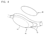
- FIG. 4 an optical device according to a second exemplary embodiment will be described with reference to FIG. 4 , FIG. 5A, and FIG. 5B .
- the optical device includes: an outer lens unit 10 having a front lens 14; an inner lens unit 20 engaged with the inner wall of the outer lens unit 10 to define an accommodation space 25 having a predetermined size between the outer lens unit 10 and the inner lens unit 20; a heat-blocking material disposed in the accommodation space 25 to block the transfer of heat; and a coating 22 formed on the inner wall surface of the outer lens unit 10 or the inner lens unit 20.
- the heat-blocking material is air
- the coating 22 is one selected from among a UV coating, a ceramic coating, a silicone coating, or an anti-fog coating.
- the outer lens unit 10 includes a frame 12 and a front lens 14.
- the frame 12 defines the outer shape of the optical device while supporting the entire weight of the optical device.
- the frame 12 is brought into close contact to the portion of a user around an eye.
- the front lens 14 is disposed in the central portion of the frame 12.
- the frame 12 be formed of a flexible material (e.g. by molding) such that the frame 12 does not cause an inconvenience to the user when the frame 12 is brought into close contact to the portion of the user around an eye.
- the front lens 14 be formed integrally with the frame 12 (e.g. by molding). Alternatively, the front lens 14 may be engaged with the frame 12.
- a concave recess having a predetermined size may be formed in the inner wall of the frame 12 in order to prevent the inner lens unit 20 from being dislodged from the frame 12.
- the inner lens unit 20 is engaged with the inner wall of the frame 12 at a predetermined distance from the front lens 14 such that the accommodation space 25 having a predetermined size is defined between the inner lens unit 20 and the front lens 14, the heat-blocking material being accommodated in the accommodation space 25.
- the heat-blocking material interposed between the outer lens unit 10 and the inner lens unit 20 is air.
- a coating 22 is formed on the inner wall surface of at least one of the outer lens unit 10 and the inner lens unit 20 in order to increase the ability to block the transfer of heat.
- the coating 22 may be implemented as a UV coating, a ceramic coating, a silicone coating, or an anti-fog film.
- the accommodation space 25 is formed by engaging the inner lens unit 20 with a predetermined portion of the outer lens unit 10, and the heat-blocking material is injected through the injection hole 16.
- the anti-leakage unit 30 is abutted to and is subsequently engaged with the outer lens unit 10, such that the stopper lug 32 is fitted into the injection hole 16, thereby preventing the heat-blocking material from leaking from the accommodation space 25.
- the heat-blocking material is filled in the space between the front lens 14 and the inner lens unit 20, thereby preventing the transfer of heat therebetween that would otherwise be caused by a difference in temperatures between the outer lens unit 10 and the inner lens unit 20.
Landscapes
- Physics & Mathematics (AREA)
- General Physics & Mathematics (AREA)
- Optics & Photonics (AREA)
- Health & Medical Sciences (AREA)
- Ophthalmology & Optometry (AREA)
- Chemical & Material Sciences (AREA)
- Chemical Kinetics & Catalysis (AREA)
- General Health & Medical Sciences (AREA)
- Eyeglasses (AREA)
- Lens Barrels (AREA)
- Non-Portable Lighting Devices Or Systems Thereof (AREA)
Applications Claiming Priority (1)
| Application Number | Priority Date | Filing Date | Title |
|---|---|---|---|
| KR1020140193212A KR101530012B1 (ko) | 2014-12-30 | 2014-12-30 | 김서림 방지용 광학소자 |
Publications (2)
| Publication Number | Publication Date |
|---|---|
| EP3040752A2 true EP3040752A2 (fr) | 2016-07-06 |
| EP3040752A3 EP3040752A3 (fr) | 2016-09-21 |
Family
ID=53519357
Family Applications (1)
| Application Number | Title | Priority Date | Filing Date |
|---|---|---|---|
| EP15202275.2A Withdrawn EP3040752A3 (fr) | 2014-12-30 | 2015-12-23 | Dispositif optique antibuée |
Country Status (6)
| Country | Link |
|---|---|
| US (1) | US20160187545A1 (fr) |
| EP (1) | EP3040752A3 (fr) |
| JP (1) | JP2016126344A (fr) |
| KR (1) | KR101530012B1 (fr) |
| CN (1) | CN105739119A (fr) |
| TW (1) | TW201632956A (fr) |
Families Citing this family (5)
| Publication number | Priority date | Publication date | Assignee | Title |
|---|---|---|---|---|
| CN111345939A (zh) * | 2020-03-17 | 2020-06-30 | 上海市肺科医院(上海市职业病防治院) | 一种带有眼部舒缓功能的智能温控护目镜 |
| US20210362007A1 (en) * | 2020-05-20 | 2021-11-25 | Flipturn Design | Lens for swim goggles and dive masks |
| CN112987304B (zh) * | 2021-02-20 | 2022-11-15 | 歌尔股份有限公司 | 一种防雾镜筒模组及智能头戴设备 |
| KR20220103877A (ko) * | 2021-06-03 | 2022-07-25 | 임채현 | 박막으로 구분된 공간을 갖는 액체 렌즈 구성을 통한 김서림 방지 장치 및 이를 포함하는 렌즈 |
| KR102909591B1 (ko) * | 2022-08-19 | 2026-01-07 | 한국로봇융합연구원 | 멀티모달 센서모듈 및 그 제조방법 |
Citations (1)
| Publication number | Priority date | Publication date | Assignee | Title |
|---|---|---|---|---|
| KR20100077789A (ko) | 2008-12-29 | 2010-07-08 | 박기범 | 김 서림 방지용 광학소자 |
Family Cites Families (7)
| Publication number | Priority date | Publication date | Assignee | Title |
|---|---|---|---|---|
| US5497268A (en) * | 1993-04-14 | 1996-03-05 | Ithaca Research Corporation | Hermetically sealed polished optical surface |
| KR19990012946U (ko) * | 1997-09-06 | 1999-04-15 | 이범규 | 이중렌즈 물안경 |
| US6049917A (en) * | 1998-01-23 | 2000-04-18 | Smith Sport Optics | Air injection sports goggle and method |
| KR200218096Y1 (ko) * | 1998-06-29 | 2001-04-02 | 이기주 | 수중안경 |
| US6772448B1 (en) * | 2001-12-14 | 2004-08-10 | Energy Related Devices, Inc. | Non-fogging goggles |
| EP2530511B1 (fr) * | 2010-01-29 | 2015-11-25 | Citizen Holdings Co., Ltd. | Procédé de fabrication de lunettes électroniques et de lentilles à cristaux liquides |
| US8182086B2 (en) * | 2010-09-20 | 2012-05-22 | Lak Cheong | Eyeglass frame, eyewear, and an eyewear assembly method |
-
2014
- 2014-12-30 KR KR1020140193212A patent/KR101530012B1/ko active Active
-
2015
- 2015-12-22 US US14/978,529 patent/US20160187545A1/en not_active Abandoned
- 2015-12-23 EP EP15202275.2A patent/EP3040752A3/fr not_active Withdrawn
- 2015-12-24 TW TW104143573A patent/TW201632956A/zh unknown
- 2015-12-28 JP JP2015256102A patent/JP2016126344A/ja active Pending
- 2015-12-30 CN CN201511018695.7A patent/CN105739119A/zh active Pending
Patent Citations (1)
| Publication number | Priority date | Publication date | Assignee | Title |
|---|---|---|---|---|
| KR20100077789A (ko) | 2008-12-29 | 2010-07-08 | 박기범 | 김 서림 방지용 광학소자 |
Also Published As
| Publication number | Publication date |
|---|---|
| EP3040752A3 (fr) | 2016-09-21 |
| JP2016126344A (ja) | 2016-07-11 |
| CN105739119A (zh) | 2016-07-06 |
| TW201632956A (zh) | 2016-09-16 |
| US20160187545A1 (en) | 2016-06-30 |
| KR101530012B1 (ko) | 2015-06-19 |
Similar Documents
| Publication | Publication Date | Title |
|---|---|---|
| EP3040752A2 (fr) | Dispositif optique antibuée | |
| US8542325B2 (en) | Color changing contact lenses | |
| ES2759618T3 (es) | Dispositivo electrónico que incluye una carcasa de vidrio | |
| WO2018005833A3 (fr) | Film protecteur pour afficheur en polyuréthane à faible tg | |
| JP3213658U (ja) | 曇りが防止されたゴーグル | |
| ES2968630T3 (es) | Conformado de una lente oftálmica | |
| WO2017214105A3 (fr) | Film d'affichage protecteur à base d'acrylate de polyuréthane | |
| JP5823091B2 (ja) | 可変焦点光学レンズ | |
| KR20180081043A (ko) | 안경 렌즈와 홀로그램 광학 소자를 통합시키는 시스템, 아티클 및 방법 | |
| AR070855A1 (es) | Lentes de contacto rotacionalmente estabilizados y los metodos para su diseno | |
| EP2174966A4 (fr) | Matériau optique et lentille ophtalmique faite de celui-ci | |
| USD863563S1 (en) | Strapped bandage with heating/cooling pocket | |
| EP3769342A4 (fr) | Photodétecteurs infrarouges à cavité résonante dans le plan dotés d'absorbeurs totalement appauvris | |
| WO2016087686A1 (fr) | Dispositif réglable permettant d'accoupler et de voir à courte distance un téléphone intelligent | |
| FR2884622B1 (fr) | Verre ophtalmique comprenant une couche d'indice de refraction variable | |
| BRPI0611969B8 (pt) | materiais e dispositivo otorrinolaringológico e oftálmico, e lente intraocular | |
| US20210361020A1 (en) | Display Embedded Visor Helmet Mounted Display | |
| EP3218764B1 (fr) | Lunettes fermées avec lentilles optiques intégrées | |
| ES2770110T3 (es) | Pantalla protectora con porción arqueada de lente que tiene una curvatura vertical que varía horizontalmente | |
| USD608815S1 (en) | Swimming goggles with black-out lenses | |
| US20160051410A1 (en) | Waterproof goggle | |
| US20220390742A1 (en) | Anti-fog device having liquid lens assembly with space isolated by thin film and lens including the same | |
| US8267513B2 (en) | Attachment mechanism for eye glass shield | |
| KR101805467B1 (ko) | 탈착 필름 렌즈 | |
| JP2013533047A (ja) | 二重レンズスキー用ゴーグル |
Legal Events
| Date | Code | Title | Description |
|---|---|---|---|
| PUAI | Public reference made under article 153(3) epc to a published international application that has entered the european phase |
Free format text: ORIGINAL CODE: 0009012 |
|
| AK | Designated contracting states |
Kind code of ref document: A2 Designated state(s): AL AT BE BG CH CY CZ DE DK EE ES FI FR GB GR HR HU IE IS IT LI LT LU LV MC MK MT NL NO PL PT RO RS SE SI SK SM TR |
|
| AX | Request for extension of the european patent |
Extension state: BA ME |
|
| PUAL | Search report despatched |
Free format text: ORIGINAL CODE: 0009013 |
|
| AK | Designated contracting states |
Kind code of ref document: A3 Designated state(s): AL AT BE BG CH CY CZ DE DK EE ES FI FR GB GR HR HU IE IS IT LI LT LU LV MC MK MT NL NO PL PT RO RS SE SI SK SM TR |
|
| AX | Request for extension of the european patent |
Extension state: BA ME |
|
| RIC1 | Information provided on ipc code assigned before grant |
Ipc: G02B 27/01 20060101ALI20160816BHEP Ipc: G02C 7/02 20060101ALI20160816BHEP Ipc: G02B 7/00 20060101AFI20160816BHEP |
|
| STAA | Information on the status of an ep patent application or granted ep patent |
Free format text: STATUS: THE APPLICATION IS DEEMED TO BE WITHDRAWN |
|
| 18D | Application deemed to be withdrawn |
Effective date: 20170322 |