EP3042035B1 - Method for isolation of a permeable zone in a subterranean well - Google Patents
Method for isolation of a permeable zone in a subterranean well Download PDFInfo
- Publication number
- EP3042035B1 EP3042035B1 EP14842220.7A EP14842220A EP3042035B1 EP 3042035 B1 EP3042035 B1 EP 3042035B1 EP 14842220 A EP14842220 A EP 14842220A EP 3042035 B1 EP3042035 B1 EP 3042035B1
- Authority
- EP
- European Patent Office
- Prior art keywords
- well
- flushing
- tool
- pipe body
- pipe
- Prior art date
- Legal status (The legal status is an assumption and is not a legal conclusion. Google has not performed a legal analysis and makes no representation as to the accuracy of the status listed.)
- Active
Links
Images




Classifications
-
- E—FIXED CONSTRUCTIONS
- E21—EARTH OR ROCK DRILLING; MINING
- E21B—EARTH OR ROCK DRILLING; OBTAINING OIL, GAS, WATER, SOLUBLE OR MELTABLE MATERIALS OR A SLURRY OF MINERALS FROM WELLS
- E21B33/00—Sealing or packing boreholes or wells
- E21B33/10—Sealing or packing boreholes or wells in the borehole
- E21B33/13—Methods or devices for cementing, for plugging holes, crevices or the like
- E21B33/14—Methods or devices for cementing, for plugging holes, crevices or the like for cementing casings into boreholes
-
- E—FIXED CONSTRUCTIONS
- E21—EARTH OR ROCK DRILLING; MINING
- E21B—EARTH OR ROCK DRILLING; OBTAINING OIL, GAS, WATER, SOLUBLE OR MELTABLE MATERIALS OR A SLURRY OF MINERALS FROM WELLS
- E21B33/00—Sealing or packing boreholes or wells
- E21B33/10—Sealing or packing boreholes or wells in the borehole
- E21B33/13—Methods or devices for cementing, for plugging holes, crevices or the like
-
- E—FIXED CONSTRUCTIONS
- E21—EARTH OR ROCK DRILLING; MINING
- E21B—EARTH OR ROCK DRILLING; OBTAINING OIL, GAS, WATER, SOLUBLE OR MELTABLE MATERIALS OR A SLURRY OF MINERALS FROM WELLS
- E21B33/00—Sealing or packing boreholes or wells
- E21B33/10—Sealing or packing boreholes or wells in the borehole
- E21B33/13—Methods or devices for cementing, for plugging holes, crevices or the like
- E21B33/138—Plastering the borehole wall; Injecting into the formation
-
- E—FIXED CONSTRUCTIONS
- E21—EARTH OR ROCK DRILLING; MINING
- E21B—EARTH OR ROCK DRILLING; OBTAINING OIL, GAS, WATER, SOLUBLE OR MELTABLE MATERIALS OR A SLURRY OF MINERALS FROM WELLS
- E21B37/00—Methods or apparatus for cleaning boreholes or wells
-
- E—FIXED CONSTRUCTIONS
- E21—EARTH OR ROCK DRILLING; MINING
- E21B—EARTH OR ROCK DRILLING; OBTAINING OIL, GAS, WATER, SOLUBLE OR MELTABLE MATERIALS OR A SLURRY OF MINERALS FROM WELLS
- E21B37/00—Methods or apparatus for cleaning boreholes or wells
- E21B37/08—Methods or apparatus for cleaning boreholes or wells cleaning in situ of down-hole filters, screens, e.g. casing perforations, or gravel packs
-
- E—FIXED CONSTRUCTIONS
- E21—EARTH OR ROCK DRILLING; MINING
- E21B—EARTH OR ROCK DRILLING; OBTAINING OIL, GAS, WATER, SOLUBLE OR MELTABLE MATERIALS OR A SLURRY OF MINERALS FROM WELLS
- E21B43/00—Methods or apparatus for obtaining oil, gas, water, soluble or meltable materials or a slurry of minerals from wells
- E21B43/11—Perforators; Permeators
-
- E—FIXED CONSTRUCTIONS
- E21—EARTH OR ROCK DRILLING; MINING
- E21B—EARTH OR ROCK DRILLING; OBTAINING OIL, GAS, WATER, SOLUBLE OR MELTABLE MATERIALS OR A SLURRY OF MINERALS FROM WELLS
- E21B41/00—Equipment or details not covered by groups E21B15/00 - E21B40/00
- E21B41/0078—Nozzles used in boreholes
Definitions
- the invention concerns a method for isolation of a permeable zone in a subterranean well, for example in a petroleum well, water well or geothermal well. Moreover, the the method may be used in any type of subterranean well, including a production well, injection well, deviation well, horizontal well, etc.
- the invention concerns a method wherein a plug is established along a longitudinal section of a well, and substantially across a complete cross section of the longitudinal section, thereby preventing undesired fluid flow to or from a permeable zone in the well.
- isolation of a permeable zone, or isolation between permeable and potential separate zones in the well may prove essential to be able to control and optimize the course of production from the well.
- fluid streams within the reservoir may change. Such changes may arise by virtue of changing the composition of fluid components in the production stream and/or by virtue of the production stream decreasing or, at worst, ceasing. Further, such changes may arise when a production well extends through a subterranean reservoir and produces oil from an upper oil zone in the reservoir, whereas a lower zone of the reservoir contains water, also referred to as formation water.
- the oil will flow into the tubular production string of the well via well perforations formed within the oil zone.
- a separating surface between underlying water and overlying oil in the reservoir will move gradually upward within the reservoir.
- such a separating surface is referred to as an oil-water contact.
- the separating surface will come into contact with, hence in flow communication with, said well perforations, which define the well's influx region from the reservoir.
- water from the reservoir will start to penetrate into the tubular production string via the well perforations and the influx region, which originally was formed exclusively within the oil zone of the reservoir.
- an increasingly larger proportion of water will be mixed together with oil during the course of production, whereby the production stream attains a gradually increasing water content during the course of production.
- oil-water contact may arise around the influx region of the well.
- oil-water contact implies that the separating surface, due to said pressure drop, is lifted up locally around the well perforations.
- water may flow into the well earlier than what would have been the case without such a water coning effect around the influx region of the well.
- the oil-water contact of the reservoir may be comprised of a transition zone instead of a relatively sharp separating surface.
- Gas coning may also arise in a production well, wherein gas from an overlying gas zone may be caused, in a similar manner, to flow prematurely into the well at a particular pressure drop across the perforations of the well in the reservoir.
- a need may exist for isolating two or more permeable zones from each other in a well in order to prevent undesired fluid flow, so-called crossflow, in an annulus in the well.
- Such permeable zones may exist as adjoining zones, or as separate zones.
- said annulus will be an annulus between a pipe string, for example a tubular production string or a tubular injection pipe, and a surrounding borehole wall, i.e. surrounding rocks (formation) defining the borehole wall.
- an outer and larger pipe string pipe body
- a further annulus will exist between the outer pipe string and the borehole wall of the well.
- Such an outer pipe string is typically used as reinforcement when a production/injection region of a well is located within weak and/or unstable reservoir rocks.
- preventing formation water from flowing from a permeable water zone and into a separate, permeable oil zone via such an annulus may be involved in context of such crossflow. It may also involve preventing the formation water from flowing, via the annulus, from the water zone and directly into a production stream from the oil zone. Conversely, it may involve preventing oil from flowing, via such an annulus, from a permeable oil zone and into a separate, permeable water zone.
- an injection well for example a well for injection of water and/or another fluid into a subterranean reservoir
- a similar need may exist for isolating one or more permeable zones in the reservoir.
- the injection stream may be conducted into a desired reservoir zone, and via well perforations located vis-à-vis the reservoir zone.
- it may involve conducting an injection water stream into, or in vicinity of, a permeable oil zone in a subterranean reservoir, thereby increasing the reservoir pressure and forcing more oil out of the reservoir.
- a need may arise for moving the injection stream to one or more other permeable zones in the reservoir, for example to zones in, or in vicinity of, the oil zone of the reservoir.
- a need may arise for isolating previous injection zones and replacing these with new injection zones in the reservoir.
- isolation of a permeable zone, or isolation between various permeable zones may prove essential to be able to control and optimize the course of injection in such a well.
- a well barrier for example a cement barrier, the purpose of which is to prevent said undesired fluid flow (crossflow) in an annulus between various permeable zones in a well, may also be exposed to large strains, i.a. in the form of substantial pressure- and temperature differences.
- the well barrier may be exposed to violent forces, including tensile-, compressive- and torsional forces. It is known that such strains over time may cause damage to such a well barrier, whereby the integrity of the barrier, hence its isolation effect, is destroyed completely or partially.
- such undesired fluid flow (crossflow) may arise in annuli behind, for example, casings, liners, production pipes and injection pipes. This may reduce or render impossible, in the worst case, further production from, or possibly injection into, a subterranean well.
- CA 2896277 A1 corresponding to WO 2013/122480 A9 , is considered to be relevant prior art and discloses a method for establishment of a new well path from an existing well.
- a cross-sectional plug of fluidized plugging material is formed in the well in order to provide mechanical stability around the entrance of the new well path to be formed from the well.
- the object of the invention is to remedy or to reduce at least one of the disadvantages of the prior art, or at least to provide a useful alternative to the prior art.
- the invention concerns a method of preventing undesired fluid flow to or from a permeable zone in a subterranean production or injection well, wherein the well, at least in a portion where the isolation is to be carried out, is provided with a pipe body, the method comprising the following steps:
- This configuration of the at least one outlet in the flushing tool ensures that a very effective flushing and cleaning of both the pipe body and the annulus outside the pipe body is achieved. This ensures good filling and good adhesion of the subsequent plugging material both in the pipe body and in the annulus.
- Said pipe body may be comprised of a well pipe of a type known per se, for example of a casing or a liner.
- the pipe body may also be a part of a longer pipe string.
- said surrounding well body normally will be comprised of a borehole wall, i.e. of rocks (formation) defining the borehole wall, and then within the region of the well comprising said longitudinal section L1 to be isolated. This is discussed above.
- the surrounding well body may be comprised of another and larger pipe body, i.e. with a larger diameter, than the former pipe body, whereby a pipe-in-pipe constellation is present within this region of the well.
- a pipe-in-pipe constellation is present within this region of the well.
- said (primary) pipe body may be comprised of a tubular production string in a production well.
- this pipe body may be comprised of a tubular injection string in an injection well.
- the present perforation tool may comprise a perforation gun of a type known per se.
- a perforation gun comprises explosive charges arranged in a desired manner for allowing a corresponding arrangement of holes to be made through the pipe wall of the pipe body.
- Other types of perforation tools or cutting tools may also be used in the present method, for example a water cutting tool based on abrasive perforation.
- Such perforation or cutting through the pipe wall of the pipe body is appropriate to ensure good circulation of a plugging material from the inside of the pipe body and out into the annulus (possibly the annuli) at the outside of the pipe body.
- the perforation step may be carried out in an undamaged/unperforated portion of the pipe body, or against an already perforated portion of the pipe body.
- a preferred distribution of holes in the pipe body may be in the order of 12 holes per foot arranged in a 135/45 degree phase within said longitudinal section L1.
- a plug covering substantially a complete cross section T1 of the well it is possible to isolate one or more permeable zones in a subterranean well.
- This may prove advantageous in, for example, a case where it is desirable to isolate a particular permeable zone, or where it is desirable to prevent undesired fluid flow (crossflow) in an annulus behind a pipe body in the well, for example in an annulus behind a tubular production string or a tubular injection string.
- the case may be that a previously set barrier element has lost its integrity, whereby undesired fluid production from one permeable formation/zone to another permeable formation/zone takes place via such an annulus.
- a plug covering the complete cross section will be able to isolate the formation/zone, which is producing the undesired fluid flow, from the other, receiving formation/zone in the well.
- Various such well situations are also described in further detail above.
- the present flushing tool is used both for flushing and plugging of the longitudinal section L1 of the well.
- the flushing tool is primarily intended for reuse and, further, may be readily modified for various well specific purposes.
- the present method may comprise disposing and anchoring a plug base in the pipe body, and below the longitudinal section L1 of the well.
- the plug base may comprise a mechanical plug, and possible a packer element, of a type known per se.
- the longitudinal section L1 is located far from the bottom of the pipe body, it may be necessary to set such a plug base so as to form a base for the fluidized plugging material in the subsequent plugging operation, i.e. in steps (D) and (E) of the method.
- the longitudinal section L1 is located at a relatively short distance from the bottom of the pipe body, it may be unnecessary to set such a plug base in the pipe body. Instead, the fluidized plugging material is filled from the bottom of the pipe body and upward until the plugging material covers the longitudinal section L1 of the well.
- the flushing tool may comprise a first section for discharge of the flushing fluid, and a second section for discharge of the fluidized plugging material.
- the first section may be arranged with an optimum configuration and size of outlets for optimum discharge of the flushing fluid
- the second section may be arranged with an optimum configuration and size of outlets for optimum discharge of the fluidized plugging material.
- outlets for the plugging material possibly may be larger than the outlets for the flushing fluid.
- the flushing tool may also be formed with several outlets, wherein the outlets are angled within ⁇ 80° of a plane being perpendicular to the longitudinal axis of the flushing tool, whereby the discharge jets from the longitudinal axis of the flushing tool also are distributed within ⁇ 80° of said plane.
- At least one of the at least one outlet in the flushing tool may be provided with a nozzle, for example a nozzle of a suitable size and/or shape.
- a nozzle for example a nozzle of a suitable size and/or shape.
- step (C) of the method i.e. the flushing step, may comprise rotating the pipe string whilst flushing, and/or moving the pipe string in a reciprocating motion whilst flushing. This may produce a very thorough cleaning on the inside and outside of the pipe body along the longitudinal section L1 of the well.
- the method may comprise adding an abrasive agent to the flushing fluid.
- an abrasive agent may comprise small particles of particulate mass, for example sand particles.
- Use of an abrasive agent in the flushing fluid may prove particularly appropriate if the annulus (possibly the annuli) outside the pipe body is completely or partially filled with, for example, cement residues, formation particles, precipitated drilling mud components and/or other casting materials or fluids. Such material may prove difficult to remove without abrasive agents present in the flushing fluid.
- an abrasive agent may thus be added to the flushing fluid in an amount corresponding to between 0.05 weight percent and 1.00 weight percent.
- circa 0.1 weight percent of an abrasive agent, for example sand, may be added to the flushing fluid.
- the flushing fluid may be discharged from the at least one outlet of the flushing tool at a discharge velocity of at least 15 metres per second. Tests show that 15 metres per second is a limit value above which the flushing tool is able to clean sufficiently.
- the flushing fluid is discharged from the at least one outlet of the flushing tool at a discharge velocity of at least 50 metres per second. Said tests also have shown that the flushing is particularly effective when the flushing fluid has a discharge velocity of at least 50 metres per second.
- the flushing fluid possibly may be discharged from the at least one outlet of the flushing tool as a substantially rotation-free discharge jet.
- the advantage thereof is that there is no need, then, for nozzles that possibly may provide a rotational effect to the discharge jet, insofar as such nozzles usually require more space for support.
- the fluidized plugging material may comprise cement slurry, which constitutes the most common plugging material in most wells.
- the fluidized plugging material may comprise a fluidized particulate mass.
- a fluidized particulate mass in a well is described, among other places, in WO 01/25594 A1 and in WO 02/081861 A1 .
- the flushing fluid may comprise drilling mud. This will be a suitable flushing fluid given that drilling mud usually is readily available and also functions as a pressure barrier in a well.
- a displacement body may be used in the present method to further displace and distribute the fluidized plugging material in the pipe body and further out into the annulus.
- a displacement body is shown and described, among other places, in Norwegian patent application No. 20120099 entitled “Apparatus and method for positioning of a fluidized plugging material in an oil well or gas well", which corresponds to international publication WO 2012/128644 A2 .
- the method may also comprise, before step (A), the following steps:
- this embodiment of the method saves on time and cost, which is of particularly great significance for well operations offshore.
- a lower end portion of the flushing tool possibly may be releasably connected to the perforation tool
- the method may also comprise, before step (C), the following steps:
- Such an embodiment of the method may prove necessary provided it is not possible to leave the perforation tool in the well, for example due to lack of space in the pipe body.
- the longitudinal section L1 possibly may be located vis- à-vis a permeable reservoir zone, thereby forming the plug vis-à-vis the permeable reservoir zone.
- the permeable reservoir zone may comprise, for example, an oil-water contact in a subterranean reservoir.
- the longitudinal section L1 possibly may be located vis-à-vis a portion of the annulus where crossflow exists, thereby forming the plug vis-à-vis this crossflow portion of the annulus.
- water from a water zone may thus be prevented from flowing into a separate oil zone via the annulus, or vice versa, or the water may be prevented from flowing into a production stream from the oil zone.
- the method may comprise, after step (E), a step of forming, by means of a perforation tool, at least one hole in the pipe body (i.e. through the wall of the pipe body) along a portion of the well located above the longitudinal section L1 where the plug has been set and covers substantially the complete cross section T1 of the well.
- new perforations may be formed higher up in an oil zone in a reservoir after having isolated an underlying oil-water contact by means of such a plug.
- the method may comprise, after step (E), a step (F) of drilling out a central, through-going portion of the plug in the pipe body, whereby at least a cross-sectional section T3 of the plug remains in the annulus outside the pipe body.
- the method may comprise, after step (F), a step of forming, by means of a perforation tool, at least one hole in the pipe body (i.e. through the wall of the pipe body) along a portion of the well located below the longitudinal section L1 where the plug has been set and drilled out.
- This may be desirable in a case where it is to be produced from, or injected into, a permeable well zone located below the plug.
- reference numeral 1 denotes a subterranean production well within which the present method is used.
- Well fluids and already established pressure barriers which will be known to a skilled person, are not shown in the Figures.
- Figure 1 shows a casing 21 extending down into the production well 1 and forming a radial boundary between a well path 2 and surrounding rocks 7 defining a borehole wall 71 in this portion of the well 1.
- a pipe body 211 here in the form of a production pipe, is suspended from a lower portion of the casing 21 and extends further down into a producing portion of the well 1.
- the production pipe 211 is provided with perforations 212, which are formed vis-à-vis a subterranean reservoir 8, and which are in flow communication with the reservoir 8. Thereby, reservoir fluids may flow from the reservoir 8, through the perforations 212 and into the production pipe 211. Further, the production pipe 211 is connected to an overlying connection pipe 210.
- the production pipe 211 and the connection pipe 210 constitute a tubular production string extending through the entire the well 1 and up to surface.
- the tubular production string is formed so as to have one and the same inner diameter throughout the complete length thereof.
- a production valve 221 of a type known per se is also disposed in the connection pipe 210 for allowing the production stream to be closed off, if required.
- Figure 1 shows a separating surface 9 (oil-water contact) between a permeable water zone 81 and an overlying, permeable oil zone 82.
- the separating surface 9 moves upward in the reservoir 8 (and possibly cones, as discussed above) until water 10 from the water zone 81 starts to flow into and through the perforations 212 so as to mix with oil 11 from the oil zone 82.
- such undesired water influx is shown with arrows pointing into and toward the perforations 212.
- the resulting production stream in the tubular production string 211, 210 will contain water 10 that gradually may replace, fully or partially, the influx of oil 11 into the production pipe 211. Obviously, this is an undesirable situation.
- Figure 1 shows only perforations 212 as they appear at this stage of the course of production of the well 1, i.e. where the perforations 212 are located at an upper portion of the oil zone 82. As such, it is normal to form new perforations 212 higher up in the oil zone 82 as the oil zone 82 is drained for oil 11 and the separating surface 9 moves upward in the reservoir 8.
- a mechanical plug is oftentimes set in the production pipe 211, and immediately below the new perforations 212, in order to prevent influx of water 10 from deeper regions of the water zone 81.
- water 10 from such deeper regions of the water zone 81 may enter and mix with the production stream via an annulus 5 located between the production pipe 211 and a surrounding borehole wall 72 defining, among other things, the producing portion of the well 1. This is not shown in Figure 1 .
- such new perforations 214 in an embodiment not shown, just as well may be formed in a separate petroleum reservoir located above the reservoir 8 in the well 1.
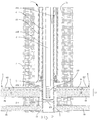
- Figure 2 shows the well 1 after having set a plug base 23, for example a mechanical plug, in the production pipe 211 below a longitudinal section L1 of the well 1 desired to be plugged, and after having lowered a perforation tool 33 into the production pipe 211 on a lower end of a pipe string 3.
- the perforation tool 33 is positioned above the plug base 23 and along the longitudinal section L1, which includes the existing perforations 212.
- the perforation tool 33 may be a perforation gun of a type known per se.
- the perforation tool 33 is used to form new perforations 213 in the production pipe 211, and immediately below the existing perforations 212.
- Both the existing and the new perforations 212, 213 are to be used during the subsequent washing and plugging, as shown in Figure 4 .
- the existing perforations 212 satisfy the requirements with respect to shape, positioning and density for allowing an effective flushing- and plugging operation to be carried out thereafter, it will not be necessary to form new perforations 213.
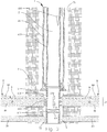
- Figure 3 shows the well 1 after the perforation tool 33 has formed new perforations 213 in the production pipe 211 within the longitudinal section L1 to be plugged, and after having pulled the pipe string 3 with the perforation tool 33 out of the well 1.
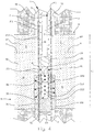
- FIG 4 shows the well 1 after having lowered a combined flushing- and plugging tool 35, hereinafter termed a flushing tool, into the production pipe 211 and onto the longitudinal section L1, and whilst the flushing tool 35 is in the process of flushing the production pipe 211 and the external annulus 5 via the perforations 212, 213 in the production pipe 211.
- perforation is carried out in one trip down into the well 1 (cf. Figure 2 ), whereas flushing and plugging are carried out in a separate trip down into the well 1.
- perforation, flushing and plugging may be carried out in one and the same trip trip down into the well 1, which is not shown here.
- FIG 4 also shows a flushing fluid 36, for example drilling mud, being pumped down through the pipe string 3, out through several flow-through outlets 351 in the flushing tool 35, into the production pipe 211 and further out into the annulus 5 via perforations 212, 213 in the production pipe 211. By so doing, both the production pipe 211 and the annulus 5 are cleaned.
- the discharge jets of the flushing fluid 36 from the flushing tool 35, and its subsequent flow direction, is indicated with arrows in Figure 4 .
- the flushing fluid 36 discharges at high velocity from various outlets 351 in a first (and lower) section 352 of the flushing tool 35.
- a first ball (not shown) is dropped down through the pipe string 3 so as to seat in a first seat (not shown) disposed below the outlets 351 in the first section 352 of the flushing tool 35.
- the outlets 351 typically will be provided with nozzles in order to concentrate the discharge jets and achieve the desired concentration of the flushing fluid 36.
- the discharge jets from the outlets 351 possibly may be rotation-free.
- the various outlets 351 are angled in such a manner that the discharge jets have dissimilar discharge angles relative to a plane being perpendicular to a longitudinal axis of the flushing tool 35. This is indicated in Figure 4 , too.
- FIG. 4 also shows liberated particles 40 flowing, together with the flushing fluid 36, upward in the production pipe 211 upon having been flushed and liberated in the annulus 5, subsequently flowing into the production pipe 211 via perforations 212, 213 therein.
- a curved arrow at an upper portion of the pipe string 3 indicates that the flushing tool 35 rotates along with the pipe string 3 whilst flushing.
- the pipe string 3 may be moved in a reciprocating motion whilst flushing. Such motions ensure an even more thorough and more effective flushing and cleaning of the production pipe 211 and the annulus 5.
- the flushing also ensures better adhesion for a subsequent plugging material, which in this exemplary embodiment is comprised of cement slurry 37.
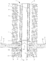
- FIG. 5 shows, in a somewhat larger scale and detail, said cement slurry 37 when subsequently being pumped down through the pipe string 3, out through the flushing tool 35, into the production pipe 211 and further out into the annulus 5 via the perforations 212, 213 in the production pipe 212.
- cement slurry 37 is placed above the plug base 23, and along the longitudinal section L1 of the well 1, as shown in Figure 5 .
- the cement slurry 37 is now discharging from various outlets 351 in a second (and upper) section 353 of the flushing tool 35.
- a second and larger ball (not shown) is dropped down through the pipe string 3 so as to seat in a second and larger seat (not shown) disposed immediately below the outlets 351 in the second section 353 of the flushing tool 35.
- Activation by means of such balls constitutes prior art.
- a curved arrow at the upper portion of the pipe string 3 indicates that the flushing tool 35 rotates along with the pipe string 3 whilst pumping cement slurry 37.
- the pipe string 3 may be moved in a reciprocating motion whilst pumping cement slurry 37.
- the pipe string 3 is also provided with a helical displacement body 39 being rotated and moved in the cement slurry 37 in the production pipe 211, during the pumping, to further displace and distribute the cement slurry 37 in the production pipe 211 and further out into the annulus 5.
- a displacement body apparatus
- NO 20120099 which corresponds to WO 2012/128644 A2 .
- Figure 6 shows the cement slurry 37 after having cured and set in the well 1 so as to form a plug 25 of cured cement.
- the cement plug 25 covers substantially a complete cross section T1 of the well 1 within the longitudinal section L1, and also a portion of the production pipe 211 down to the plug base 23.
- Figure 7 shows the well 1 immediately after having drilled out a central, through-going portion of the cement plug 25 by means of a drilling tool 31.
- Figure 8 shows the well 1 after having removed the drilling tool 31 from the well 1 so as to leave a remaining cross-sectional section T3 of the cement plug 25 in the annulus 5, and within the longitudinal section L1.
- the remaining cross-sectional section T3 of the cement plug 25 forms a barrier 51 between the production pipe 211 and the borehole wall 72 defining the reservoir 8. Thereby, the entire reservoir 8 is isolated from the rest of the well 1.
- Figure 9 shows the well 1 after having formed said new perforations 214 in the production pipe 211, and vis-à-vis the separate and deeper oil reservoir 20 in the well 1.
- the distance between the reservoirs 8 and 20 may be very large, commonly in the order of kilometres.
- the Figure also shows arrows indicating fluid flow from the oil reservoir 20 and into the production pipe 211 via the new perforations 214.
- Figure 10 shows a similar production well 1, wherein water 10' from a deeper water zone (not shown) in the well 1 flows in an undesired manner in an annulus 5 behind a production pipe 211 and upward to perforations 212 formed directly vis-à-vis a producing, permeable oil zone 82 in a reservoir 8.
- the flow of water 10' in the annulus 5 is also depicted with arrows in the Figure.
- the water 10' flows into the production pipe 211 via the perforations 212 and mixes into the production stream together with oil 11 from the reservoir 8.
- the undesired water flow may be a result of a poor and/or difficult cementing job previously in the well 1.
- FIG 11 shows the well 1 after having set a cement plug 25 in a plugging region below the reservoir 8 and the perforations 212 in the production pipe 211.
- the cement plug 25 has been formed and set in the same manner as described above with reference to Figures 4-6 .
- the plug 25 in this second embodiment also has been set across the complete cross section of the well 1 so as to form a barrier 51 in said plugging region of the well 1.
Landscapes
- Geology (AREA)
- Life Sciences & Earth Sciences (AREA)
- Engineering & Computer Science (AREA)
- Mining & Mineral Resources (AREA)
- Environmental & Geological Engineering (AREA)
- Fluid Mechanics (AREA)
- Physics & Mathematics (AREA)
- General Life Sciences & Earth Sciences (AREA)
- Geochemistry & Mineralogy (AREA)
- Earth Drilling (AREA)
- Reciprocating Pumps (AREA)
- Consolidation Of Soil By Introduction Of Solidifying Substances Into Soil (AREA)
- Excavating Of Shafts Or Tunnels (AREA)
- Separation Using Semi-Permeable Membranes (AREA)
Applications Claiming Priority (2)
| Application Number | Priority Date | Filing Date | Title |
|---|---|---|---|
| NO20131213A NO339191B1 (no) | 2013-09-06 | 2013-09-06 | Fremgangsmåte for isolering av en permeabel sone i en underjordisk brønn |
| PCT/NO2014/050151 WO2015034369A1 (en) | 2013-09-06 | 2014-08-26 | Method for isolation of a permeable zone in a subterranean well |
Publications (3)
| Publication Number | Publication Date |
|---|---|
| EP3042035A1 EP3042035A1 (en) | 2016-07-13 |
| EP3042035A4 EP3042035A4 (en) | 2017-06-21 |
| EP3042035B1 true EP3042035B1 (en) | 2021-06-09 |
Family
ID=52628710
Family Applications (1)
| Application Number | Title | Priority Date | Filing Date |
|---|---|---|---|
| EP14842220.7A Active EP3042035B1 (en) | 2013-09-06 | 2014-08-26 | Method for isolation of a permeable zone in a subterranean well |
Country Status (8)
| Country | Link |
|---|---|
| US (1) | US10301904B2 (da) |
| EP (1) | EP3042035B1 (da) |
| AU (1) | AU2014315748B2 (da) |
| CA (1) | CA2923158C (da) |
| DK (1) | DK3042035T3 (da) |
| GB (1) | GB2531684B (da) |
| NO (1) | NO339191B1 (da) |
| WO (1) | WO2015034369A1 (da) |
Families Citing this family (11)
| Publication number | Priority date | Publication date | Assignee | Title |
|---|---|---|---|---|
| NO336038B1 (no) * | 2013-08-16 | 2015-04-27 | Hydra Systems As | Fremgangsmåte for etablering av en ny brønnbane fra en eksisterende brønn |
| NO339191B1 (no) | 2013-09-06 | 2016-11-14 | Hydra Systems As | Fremgangsmåte for isolering av en permeabel sone i en underjordisk brønn |
| NO340959B1 (en) * | 2015-06-10 | 2017-07-31 | Hydra Systems As | A method of plugging and abandoning a well |
| NO343153B1 (en) * | 2015-12-17 | 2018-11-19 | Hydra Systems As | A method of assessing the integrity status of a barrier plug |
| WO2018034671A1 (en) * | 2016-08-19 | 2018-02-22 | Halliburton Energy Services, Inc. | Utilizing electrically actuated explosives downhole |
| US10961828B2 (en) * | 2016-08-19 | 2021-03-30 | Halliburton Energy Services, Inc. | Utilizing electrically actuated explosives downhole |
| GB2568529B (en) * | 2017-11-20 | 2021-02-24 | Weatherford Uk Ltd | Method and apparatus for washing an annulus |
| NO343780B1 (no) * | 2018-02-21 | 2019-06-03 | Hydra Systems As | A method of assessing the integrity status of a barrier plug |
| NO346617B1 (en) | 2020-03-09 | 2022-10-31 | Hydra Systems As | A fluid diverter tool, system and method of diverting a fluid flow in a well |
| CA3192365A1 (en) * | 2020-08-19 | 2022-02-24 | Conocophillips Company | Behind casing wash and cement |
| US11649702B2 (en) * | 2020-12-03 | 2023-05-16 | Saudi Arabian Oil Company | Wellbore shaped perforation assembly |
Family Cites Families (103)
| Publication number | Priority date | Publication date | Assignee | Title |
|---|---|---|---|---|
| GB258808A (en) | 1926-04-24 | 1926-09-30 | Kobe Inc | Method of and apparatus for cutting slots in oil well casing |
| US2156207A (en) | 1938-02-04 | 1939-04-25 | James E Terrill | Apparatus for washing and cementing oil wells |
| US2426164A (en) | 1943-12-29 | 1947-08-26 | Christian W Breukelman | Cementing tool for oil wells |
| US2512801A (en) | 1947-02-17 | 1950-06-27 | Shell Dev | Perforation washer |
| US2591807A (en) | 1947-08-23 | 1952-04-08 | Haskell M Greene | Oil well cementing |
| US2998721A (en) | 1956-12-27 | 1961-09-05 | Paul A Gawlik | Tool for detecting pipe leaks |
| US3064734A (en) * | 1958-10-13 | 1962-11-20 | Great Lakes Carbon Corp | Bridge plug |
| US3811499A (en) | 1971-06-07 | 1974-05-21 | Chevron Res | High pressure jet well cleaning |
| US4088191A (en) | 1972-07-24 | 1978-05-09 | Chevron Research Company | High pressure jet well cleaning |
| US3850241A (en) * | 1972-07-24 | 1974-11-26 | Chevron Res | High pressure jet well cleaning |
| US4019576A (en) * | 1973-11-23 | 1977-04-26 | William C. Finch | Oil recovery from an oil-water well |
| US3958641A (en) | 1974-03-07 | 1976-05-25 | Halliburton Company | Self-decentralized hydra-jet tool |
| US4040482A (en) | 1976-06-28 | 1977-08-09 | Vann Roy Randell | Optional fire and release tool and method |
| US4083406A (en) | 1976-11-18 | 1978-04-11 | Metz Thomas L | Method and apparatus for sealing drill casing |
| US4279306A (en) | 1979-08-10 | 1981-07-21 | Top Tool Company, Inc. | Well washing tool and method |
| US4372384A (en) | 1980-09-19 | 1983-02-08 | Geo Vann, Inc. | Well completion method and apparatus |
| US4531583A (en) | 1981-07-10 | 1985-07-30 | Halliburton Company | Cement placement methods |
| US4564226A (en) | 1981-11-02 | 1986-01-14 | Explosive Research Ltd. | System and method for increasing wall thickness on end of pipe on which thread is to be fabricated |
| US4484625A (en) | 1982-04-20 | 1984-11-27 | The Western Company Of North America | Well casing perforated zone washing apparatus |
| US4589490A (en) | 1984-11-08 | 1986-05-20 | Conoco Inc. | Well bore recompletion |
| US4688640A (en) * | 1986-06-20 | 1987-08-25 | Shell Offshore Inc. | Abandoning offshore well |
| US4756371A (en) | 1986-12-15 | 1988-07-12 | Brieger Emmet F | Perforation apparatus and method |
| US4759408A (en) | 1987-06-08 | 1988-07-26 | Texaco Inc. | Method of shutting off a portion of a producing zone in a hydrocarbon producing well |
| US4889187A (en) | 1988-04-25 | 1989-12-26 | Jamie Bryant Terrell | Multi-run chemical cutter and method |
| US4899821A (en) * | 1989-01-12 | 1990-02-13 | Hydro-Tool Company, Inc. | Method and apparatus for servicing well casing and the like |
| US5022148A (en) | 1989-04-07 | 1991-06-11 | The Babcock & Wilcox Company | Method for explosively welding a sleeve into a heat exchanger tube |
| US5111885A (en) | 1990-10-17 | 1992-05-12 | Directional Wireline Service, Inc. | Decentralized casing hole puncher |
| GB9110451D0 (en) | 1991-05-14 | 1991-07-03 | Schlumberger Services Petrol | Cleaning method |
| US5178219A (en) * | 1991-06-27 | 1993-01-12 | Halliburton Company | Method and apparatus for performing a block squeeze cementing job |
| US5320174A (en) | 1992-06-16 | 1994-06-14 | Terrell Donna K | Downhole chemical cutting tool and process |
| US5301760C1 (en) | 1992-09-10 | 2002-06-11 | Natural Reserve Group Inc | Completing horizontal drain holes from a vertical well |
| US5277251A (en) | 1992-10-09 | 1994-01-11 | Blount Curtis G | Method for forming a window in a subsurface well conduit |
| US5377757A (en) * | 1992-12-22 | 1995-01-03 | Mobil Oil Corporation | Low temperature epoxy system for through tubing squeeze in profile modification, remedial cementing, and casing repair |
| GB2275282B (en) | 1993-02-11 | 1996-08-07 | Halliburton Co | Abandonment of sub-sea wells |
| US5381631A (en) | 1993-04-15 | 1995-01-17 | Flow International Corporation | Method and apparatus for cutting metal casings with an ultrahigh-pressure abrasive fluid jet |
| GB9312727D0 (en) | 1993-06-19 | 1993-08-04 | Head Philip F | A method of abandoning a well and apparatus therefore |
| US5423387A (en) | 1993-06-23 | 1995-06-13 | Baker Hughes, Inc. | Method for sidetracking below reduced-diameter tubulars |
| US5634984A (en) * | 1993-12-22 | 1997-06-03 | Union Oil Company Of California | Method for cleaning an oil-coated substrate |
| US5402850A (en) | 1994-01-13 | 1995-04-04 | Lalande; Phillip T. | Methods of using reverse circulating tool in a well borehole |
| FR2718665B1 (fr) | 1994-04-15 | 1996-07-12 | Stolt Comex Seaway | Outil de découpe de tuyauterie immergée par jet abrasif. |
| US5435400B1 (en) | 1994-05-25 | 1999-06-01 | Atlantic Richfield Co | Lateral well drilling |
| US5924489A (en) | 1994-06-24 | 1999-07-20 | Hatcher; Wayne B. | Method of severing a downhole pipe in a well borehole |
| US5431219A (en) | 1994-06-27 | 1995-07-11 | Dowell, A Division Of Schlumberger Technology Corp. | Forming casing window off whipstock set in cement plug |
| US5474130A (en) * | 1994-08-05 | 1995-12-12 | Davis; Thomas C. | Perforation purging tool |
| US5484018A (en) | 1994-08-16 | 1996-01-16 | Halliburton Company | Method for accessing bypassed production zones |
| US5526888A (en) | 1994-09-12 | 1996-06-18 | Gazewood; Michael J. | Apparatus for axial connection and joinder of tubulars by application of remote hydraulic pressure |
| US5564500A (en) * | 1995-07-19 | 1996-10-15 | Halliburton Company | Apparatus and method for removing gelled drilling fluid and filter cake from the side of a well bore |
| US5584350A (en) | 1995-09-22 | 1996-12-17 | Weatherford U.S., Inc. | Wellbore sidetracking methods |
| US5791417A (en) | 1995-09-22 | 1998-08-11 | Weatherford/Lamb, Inc. | Tubular window formation |
| US6155343A (en) | 1996-10-25 | 2000-12-05 | Baker Hughes Incorporated | System for cutting materials in wellbores |
| US6302201B1 (en) * | 1998-02-25 | 2001-10-16 | Gregory D. Elliott | Method and apparatus for washing subsea drilling rig equipment and retrieving wear bushings |
| NO981998D0 (no) | 1998-05-04 | 1998-05-04 | Henning Hansen | FremgangsmÕte ved flerfaset tettende plugging av borehull benyttet for produksjon av hydrokarboner eller injeksjon av vµsker til nedihulls formasjoner eller unders÷kelsesborehull |
| US7188687B2 (en) | 1998-12-22 | 2007-03-13 | Weatherford/Lamb, Inc. | Downhole filter |
| US6374918B2 (en) | 1999-05-14 | 2002-04-23 | Weatherford/Lamb, Inc. | In-tubing wellbore sidetracking operations |
| NO310693B1 (no) | 1999-10-04 | 2001-08-13 | Sandaband Inc | Lösmasseplugg for plugging av en brönn |
| US6533040B2 (en) | 1999-12-03 | 2003-03-18 | Michael Gondouin | Multi-function apparatus for adding a branch well sealed liner and connector to an existing cased well at low cost |
| US6206100B1 (en) | 1999-12-20 | 2001-03-27 | Osca, Inc. | Separable one-trip perforation and gravel pack system and method |
| US6394184B2 (en) | 2000-02-15 | 2002-05-28 | Exxonmobil Upstream Research Company | Method and apparatus for stimulation of multiple formation intervals |
| US6828531B2 (en) | 2000-03-30 | 2004-12-07 | Homer L. Spencer | Oil and gas well alloy squeezing method and apparatus |
| US20020023754A1 (en) | 2000-08-28 | 2002-02-28 | Buytaert Jean P. | Method for drilling multilateral wells and related device |
| US6564868B1 (en) | 2000-10-16 | 2003-05-20 | Cudd Pressure Control, Inc. | Cutting tool and method for cutting tubular member |
| NO313923B1 (no) | 2001-04-03 | 2002-12-23 | Silver Eagle As | FremgangsmÕte for Õ hindre et fluid i Õ strömme i eller omkring et brönnrör ved hjelp av lösmasse |
| US6595289B2 (en) | 2001-05-04 | 2003-07-22 | Weatherford/Lamb, Inc. | Method and apparatus for plugging a wellbore |
| GB0207851D0 (en) | 2002-04-05 | 2002-05-15 | Sps Afos Group Ltd | Stabiliser jetting and circulating tool |
| US6832655B2 (en) | 2002-09-27 | 2004-12-21 | Bj Services Company | Method for cleaning gravel packs |
| US20040089450A1 (en) | 2002-11-13 | 2004-05-13 | Slade William J. | Propellant-powered fluid jet cutting apparatus and methods of use |
| CA2517883C (en) | 2003-03-05 | 2010-01-12 | Weatherford/Lamb, Inc. | Full bore lined wellbores |
| GB2414492B (en) | 2004-05-26 | 2008-03-05 | U W G Ltd | Apparatus and method |
| GB2424009B (en) | 2004-09-07 | 2007-09-05 | Schlumberger Holdings | Automatic tool release |
| US7168491B2 (en) | 2004-10-08 | 2007-01-30 | Buckman Jet Drilling, Inc. | Perforation alignment tool for jet drilling, perforating and cleaning |
| ATE416299T1 (de) | 2005-02-10 | 2008-12-15 | Schlumberger Technology Bv | Verfahren und vorrichtung für die konsolidierung eines bohrlochs |
| DK1840324T3 (da) | 2006-03-31 | 2012-11-26 | Schlumberger Technology Bv | Fremgangsmåde og apparat til selektiv behandling af et perforeret foringsrør |
| US8074717B2 (en) * | 2006-08-03 | 2011-12-13 | Shell Oil Company | Drilling method and downhole cleaning tool |
| US8261828B2 (en) | 2007-03-26 | 2012-09-11 | Baker Hughes Incorporated | Optimized machining process for cutting tubulars downhole |
| US20080314591A1 (en) | 2007-06-21 | 2008-12-25 | Hales John H | Single trip well abandonment with dual permanent packers and perforating gun |
| US7640983B2 (en) | 2007-07-12 | 2010-01-05 | Schlumberger Technology Corporation | Method to cement a perforated casing |
| US8020619B1 (en) | 2008-03-26 | 2011-09-20 | Robertson Intellectual Properties, LLC | Severing of downhole tubing with associated cable |
| EP2192263A1 (en) | 2008-11-27 | 2010-06-02 | Services Pétroliers Schlumberger | Method for monitoring cement plugs |
| US8307903B2 (en) | 2009-06-24 | 2012-11-13 | Weatherford / Lamb, Inc. | Methods and apparatus for subsea well intervention and subsea wellhead retrieval |
| GB2484166B (en) | 2010-07-05 | 2012-11-07 | Bruce Arnold Tunget | Cable compatible rig-less operatable annuli engagable system for using and abandoning a subterranean well |
| NO332901B1 (no) | 2009-11-10 | 2013-01-28 | Norse Cutting & Abandonment As | Fremgangsmate og anordning for a stenge en bronn i grunnen |
| NO20093545A1 (no) | 2009-12-17 | 2011-06-20 | Norse Cutting & Abandonment As | Fremgangsmate og anordning for a stenge en bronn i grunnen |
| US8550176B2 (en) | 2010-02-09 | 2013-10-08 | Halliburton Energy Services, Inc. | Wellbore bypass tool and related methods of use |
| NO335972B1 (no) * | 2011-01-12 | 2015-04-07 | Hydra Systems As | Fremgangsmåte for kombinert rengjøring og plugging i en brønn, vaskeverktøy for retningsstyrt spyling i en brønn, samt anvendelse av vaskeverktøyet |
| US8602101B2 (en) | 2011-01-21 | 2013-12-10 | Smith International, Inc. | Multi-cycle pipe cutter and related methods |
| NO335153B1 (no) | 2011-02-03 | 2014-10-06 | Tco As | Verktøy og fremgangsmåte for avstenging av en brønn |
| NO339005B1 (no) * | 2011-03-24 | 2016-11-07 | Hydra Systems As | Apparat og framgangsmåte for anbringelse av et fluidisert pluggmateriale i en brønn |
| NO336242B1 (no) | 2011-12-21 | 2015-06-29 | Wtw Solutions As | Brønnkompletteringsarrangement og fremgangsmåte for å klargjøre en brønn for oppgivelse. |
| US8584756B1 (en) | 2012-01-17 | 2013-11-19 | Halliburton Energy Sevices, Inc. | Methods of isolating annular areas formed by multiple casing strings in a well |
| US9228422B2 (en) * | 2012-01-30 | 2016-01-05 | Thru Tubing Solutions, Inc. | Limited depth abrasive jet cutter |
| NO339025B1 (no) | 2012-02-03 | 2016-11-07 | Hydra Systems As | Fremgangsmåte ved etablering av en ringromsbarriere i en underjordisk brønn |
| NO335689B1 (no) | 2012-02-17 | 2015-01-19 | Hydra Systems As | Fremgangsmåte ved etablering av en ny brønnbane fra en eksisterende brønn |
| CA2769935C (en) * | 2012-02-28 | 2020-04-14 | Canasonics Inc. | Method and system for cleaning fracture ports |
| NO336527B1 (no) * | 2012-03-09 | 2015-09-21 | Hydra Systems As | Fremgangsmåte ved soneisolering i en underjordisk brønn |
| NO339082B1 (no) * | 2012-03-09 | 2016-11-14 | Hydra Systems As | Fremgangsmåte for kombinert rengjøring og plugging i en brønn |
| US9580985B2 (en) | 2012-08-03 | 2017-02-28 | Baker Hughes Incorporated | Method of cutting a control line outside of a tubular |
| CN203008851U (zh) * | 2013-01-11 | 2013-06-19 | 李万富 | 固井旋流短节 |
| NO336445B1 (no) | 2013-02-13 | 2015-08-24 | Well Technology As | Fremgangsmåte for nedihulls kutting av minst én linje som er anordnet utenpå og langsetter en rørstreng i en brønn, og uten samtidig å kutte rørstrengen |
| NO337162B1 (no) | 2013-03-20 | 2016-02-01 | Hydra Panda As | Fremgangsmåte, system og anvendelse for plugging av en brønn |
| NO336038B1 (no) | 2013-08-16 | 2015-04-27 | Hydra Systems As | Fremgangsmåte for etablering av en ny brønnbane fra en eksisterende brønn |
| US9334712B2 (en) * | 2013-08-21 | 2016-05-10 | Archer Oil Tools As | One trip perforating and washing tool for plugging and abandoning wells |
| NO339191B1 (no) | 2013-09-06 | 2016-11-14 | Hydra Systems As | Fremgangsmåte for isolering av en permeabel sone i en underjordisk brønn |
| NO336249B1 (no) | 2014-02-18 | 2015-06-29 | Well Technology As | Hydraulisk kutteverktøy, system og fremgangsmåte for styrt hydraulisk kutting gjennom en rørvegg i en brønn, samt anvendelser av kutteverktøyet og systemet |
-
2013
- 2013-09-06 NO NO20131213A patent/NO339191B1/no unknown
-
2014
- 2014-08-26 CA CA2923158A patent/CA2923158C/en active Active
- 2014-08-26 DK DK14842220.7T patent/DK3042035T3/da active
- 2014-08-26 US US14/912,288 patent/US10301904B2/en active Active
- 2014-08-26 AU AU2014315748A patent/AU2014315748B2/en active Active
- 2014-08-26 WO PCT/NO2014/050151 patent/WO2015034369A1/en not_active Ceased
- 2014-08-26 EP EP14842220.7A patent/EP3042035B1/en active Active
- 2014-08-26 GB GB1602542.1A patent/GB2531684B/en active Active
Also Published As
| Publication number | Publication date |
|---|---|
| NO339191B1 (no) | 2016-11-14 |
| NO20131213A1 (no) | 2015-03-09 |
| WO2015034369A1 (en) | 2015-03-12 |
| AU2014315748A1 (en) | 2016-03-03 |
| EP3042035A1 (en) | 2016-07-13 |
| AU2014315748B2 (en) | 2016-06-16 |
| CA2923158C (en) | 2021-02-09 |
| EP3042035A4 (en) | 2017-06-21 |
| GB2531684A (en) | 2016-04-27 |
| GB201602542D0 (en) | 2016-03-30 |
| US20160201430A1 (en) | 2016-07-14 |
| US10301904B2 (en) | 2019-05-28 |
| DK3042035T3 (en) | 2021-06-28 |
| GB2531684B (en) | 2017-02-15 |
| CA2923158A1 (en) | 2015-03-12 |
Similar Documents
| Publication | Publication Date | Title |
|---|---|---|
| EP3042035B1 (en) | Method for isolation of a permeable zone in a subterranean well | |
| EP3307985B1 (en) | A method of plugging and abandoning a well | |
| RU2390623C2 (ru) | Однорейсовое скважинное устройство, снабженное средствами борьбы с пескопроявлением | |
| CA2822383C (en) | Method for combined cleaning and plugging in a well, a washing tool for directional washing in a well, and uses thereof | |
| EP3033479B1 (en) | Method for establishment of a new well path from an existing well | |
| EA029636B1 (ru) | Способ комбинированных очистки и закупоривания скважины и промывочное устройство для промывки скважины | |
| EP3698015B1 (en) | A system and method of cleaning an annular area in a well | |
| EP2809876B1 (en) | A method for establishment of an annulus barrier in a subterranean well | |
| US20070079967A1 (en) | Method of reducing sand production from a wellbore | |
| JP6521311B2 (ja) | 被圧水下における薬液注入工法 |
Legal Events
| Date | Code | Title | Description |
|---|---|---|---|
| PUAI | Public reference made under article 153(3) epc to a published international application that has entered the european phase |
Free format text: ORIGINAL CODE: 0009012 |
|
| 17P | Request for examination filed |
Effective date: 20160205 |
|
| AK | Designated contracting states |
Kind code of ref document: A1 Designated state(s): AL AT BE BG CH CY CZ DE DK EE ES FI FR GB GR HR HU IE IS IT LI LT LU LV MC MK MT NL NO PL PT RO RS SE SI SK SM TR |
|
| AX | Request for extension of the european patent |
Extension state: BA ME |
|
| RIN1 | Information on inventor provided before grant (corrected) |
Inventor name: DAHL, ARNT OLAV Inventor name: JENSEN, ROY INGE Inventor name: LARSEN, ARNE GUNNAR Inventor name: MYHRE, MORTEN Inventor name: ENGELSGJERD, ERLEND Inventor name: ANDERSEN, PATRICK Inventor name: OESTVOLD, ARNOLD Inventor name: IUELL, MARKUS |
|
| DAX | Request for extension of the european patent (deleted) | ||
| A4 | Supplementary search report drawn up and despatched |
Effective date: 20170523 |
|
| RIC1 | Information provided on ipc code assigned before grant |
Ipc: E21B 37/00 20060101ALI20170517BHEP Ipc: E21B 33/13 20060101AFI20170517BHEP Ipc: E21B 43/32 20060101ALI20170517BHEP |
|
| GRAP | Despatch of communication of intention to grant a patent |
Free format text: ORIGINAL CODE: EPIDOSNIGR1 |
|
| STAA | Information on the status of an ep patent application or granted ep patent |
Free format text: STATUS: GRANT OF PATENT IS INTENDED |
|
| INTG | Intention to grant announced |
Effective date: 20210312 |
|
| RBV | Designated contracting states (corrected) |
Designated state(s): AL AT BE BG CH CY CZ DE DK EE ES FI FR GR HR HU IE IS IT LI LT LU LV MC MK MT NL NO PL PT RO RS SE SI SK SM TR |
|
| GRAS | Grant fee paid |
Free format text: ORIGINAL CODE: EPIDOSNIGR3 |
|
| GRAA | (expected) grant |
Free format text: ORIGINAL CODE: 0009210 |
|
| STAA | Information on the status of an ep patent application or granted ep patent |
Free format text: STATUS: THE PATENT HAS BEEN GRANTED |
|
| RIN1 | Information on inventor provided before grant (corrected) |
Inventor name: MYHRE, MORTEN Inventor name: OESTVOLD, ARNOLD Inventor name: DAHL, ARNT OLAV Inventor name: IUELL, MARKUS Inventor name: ENGELSGJERD, ERLEND Inventor name: ANDERSEN, PATRICK Inventor name: JENSEN, ROY INGE Inventor name: LARSEN, ARNE GUNNAR |
|
| AK | Designated contracting states |
Kind code of ref document: B1 Designated state(s): AL AT BE BG CH CY CZ DE DK EE ES FI FR GR HR HU IE IS IT LI LT LU LV MC MK MT NL NO PL PT RO RS SE SI SK SM TR |
|
| REG | Reference to a national code |
Ref country code: AT Ref legal event code: REF Ref document number: 1400663 Country of ref document: AT Kind code of ref document: T Effective date: 20210615 Ref country code: CH Ref legal event code: EP |
|
| REG | Reference to a national code |
Ref country code: DK Ref legal event code: T3 Effective date: 20210623 |
|
| REG | Reference to a national code |
Ref country code: DE Ref legal event code: R096 Ref document number: 602014078059 Country of ref document: DE |
|
| REG | Reference to a national code |
Ref country code: IE Ref legal event code: FG4D |
|
| REG | Reference to a national code |
Ref country code: NL Ref legal event code: FP |
|
| REG | Reference to a national code |
Ref country code: LT Ref legal event code: MG9D |
|
| PG25 | Lapsed in a contracting state [announced via postgrant information from national office to epo] |
Ref country code: HR Free format text: LAPSE BECAUSE OF FAILURE TO SUBMIT A TRANSLATION OF THE DESCRIPTION OR TO PAY THE FEE WITHIN THE PRESCRIBED TIME-LIMIT Effective date: 20210609 Ref country code: BG Free format text: LAPSE BECAUSE OF FAILURE TO SUBMIT A TRANSLATION OF THE DESCRIPTION OR TO PAY THE FEE WITHIN THE PRESCRIBED TIME-LIMIT Effective date: 20210909 Ref country code: LT Free format text: LAPSE BECAUSE OF FAILURE TO SUBMIT A TRANSLATION OF THE DESCRIPTION OR TO PAY THE FEE WITHIN THE PRESCRIBED TIME-LIMIT Effective date: 20210609 Ref country code: FI Free format text: LAPSE BECAUSE OF FAILURE TO SUBMIT A TRANSLATION OF THE DESCRIPTION OR TO PAY THE FEE WITHIN THE PRESCRIBED TIME-LIMIT Effective date: 20210609 |
|
| REG | Reference to a national code |
Ref country code: AT Ref legal event code: MK05 Ref document number: 1400663 Country of ref document: AT Kind code of ref document: T Effective date: 20210609 |
|
| PG25 | Lapsed in a contracting state [announced via postgrant information from national office to epo] |
Ref country code: RS Free format text: LAPSE BECAUSE OF FAILURE TO SUBMIT A TRANSLATION OF THE DESCRIPTION OR TO PAY THE FEE WITHIN THE PRESCRIBED TIME-LIMIT Effective date: 20210609 Ref country code: SE Free format text: LAPSE BECAUSE OF FAILURE TO SUBMIT A TRANSLATION OF THE DESCRIPTION OR TO PAY THE FEE WITHIN THE PRESCRIBED TIME-LIMIT Effective date: 20210609 Ref country code: NO Free format text: LAPSE BECAUSE OF FAILURE TO SUBMIT A TRANSLATION OF THE DESCRIPTION OR TO PAY THE FEE WITHIN THE PRESCRIBED TIME-LIMIT Effective date: 20210909 Ref country code: GR Free format text: LAPSE BECAUSE OF FAILURE TO SUBMIT A TRANSLATION OF THE DESCRIPTION OR TO PAY THE FEE WITHIN THE PRESCRIBED TIME-LIMIT Effective date: 20210910 Ref country code: LV Free format text: LAPSE BECAUSE OF FAILURE TO SUBMIT A TRANSLATION OF THE DESCRIPTION OR TO PAY THE FEE WITHIN THE PRESCRIBED TIME-LIMIT Effective date: 20210609 |
|
| PG25 | Lapsed in a contracting state [announced via postgrant information from national office to epo] |
Ref country code: SK Free format text: LAPSE BECAUSE OF FAILURE TO SUBMIT A TRANSLATION OF THE DESCRIPTION OR TO PAY THE FEE WITHIN THE PRESCRIBED TIME-LIMIT Effective date: 20210609 Ref country code: SM Free format text: LAPSE BECAUSE OF FAILURE TO SUBMIT A TRANSLATION OF THE DESCRIPTION OR TO PAY THE FEE WITHIN THE PRESCRIBED TIME-LIMIT Effective date: 20210609 Ref country code: CZ Free format text: LAPSE BECAUSE OF FAILURE TO SUBMIT A TRANSLATION OF THE DESCRIPTION OR TO PAY THE FEE WITHIN THE PRESCRIBED TIME-LIMIT Effective date: 20210609 Ref country code: EE Free format text: LAPSE BECAUSE OF FAILURE TO SUBMIT A TRANSLATION OF THE DESCRIPTION OR TO PAY THE FEE WITHIN THE PRESCRIBED TIME-LIMIT Effective date: 20210609 Ref country code: ES Free format text: LAPSE BECAUSE OF FAILURE TO SUBMIT A TRANSLATION OF THE DESCRIPTION OR TO PAY THE FEE WITHIN THE PRESCRIBED TIME-LIMIT Effective date: 20210609 Ref country code: PT Free format text: LAPSE BECAUSE OF FAILURE TO SUBMIT A TRANSLATION OF THE DESCRIPTION OR TO PAY THE FEE WITHIN THE PRESCRIBED TIME-LIMIT Effective date: 20211011 Ref country code: RO Free format text: LAPSE BECAUSE OF FAILURE TO SUBMIT A TRANSLATION OF THE DESCRIPTION OR TO PAY THE FEE WITHIN THE PRESCRIBED TIME-LIMIT Effective date: 20210609 Ref country code: AT Free format text: LAPSE BECAUSE OF FAILURE TO SUBMIT A TRANSLATION OF THE DESCRIPTION OR TO PAY THE FEE WITHIN THE PRESCRIBED TIME-LIMIT Effective date: 20210609 |
|
| PG25 | Lapsed in a contracting state [announced via postgrant information from national office to epo] |
Ref country code: PL Free format text: LAPSE BECAUSE OF FAILURE TO SUBMIT A TRANSLATION OF THE DESCRIPTION OR TO PAY THE FEE WITHIN THE PRESCRIBED TIME-LIMIT Effective date: 20210609 |
|
| REG | Reference to a national code |
Ref country code: DE Ref legal event code: R097 Ref document number: 602014078059 Country of ref document: DE |
|
| REG | Reference to a national code |
Ref country code: CH Ref legal event code: PL |
|
| PG25 | Lapsed in a contracting state [announced via postgrant information from national office to epo] |
Ref country code: MC Free format text: LAPSE BECAUSE OF FAILURE TO SUBMIT A TRANSLATION OF THE DESCRIPTION OR TO PAY THE FEE WITHIN THE PRESCRIBED TIME-LIMIT Effective date: 20210609 |
|
| PLBE | No opposition filed within time limit |
Free format text: ORIGINAL CODE: 0009261 |
|
| STAA | Information on the status of an ep patent application or granted ep patent |
Free format text: STATUS: NO OPPOSITION FILED WITHIN TIME LIMIT |
|
| REG | Reference to a national code |
Ref country code: BE Ref legal event code: MM Effective date: 20210831 |
|
| PG25 | Lapsed in a contracting state [announced via postgrant information from national office to epo] |
Ref country code: LI Free format text: LAPSE BECAUSE OF NON-PAYMENT OF DUE FEES Effective date: 20210831 Ref country code: CH Free format text: LAPSE BECAUSE OF NON-PAYMENT OF DUE FEES Effective date: 20210831 |
|
| 26N | No opposition filed |
Effective date: 20220310 |
|
| PG25 | Lapsed in a contracting state [announced via postgrant information from national office to epo] |
Ref country code: LU Free format text: LAPSE BECAUSE OF NON-PAYMENT OF DUE FEES Effective date: 20210826 Ref country code: AL Free format text: LAPSE BECAUSE OF FAILURE TO SUBMIT A TRANSLATION OF THE DESCRIPTION OR TO PAY THE FEE WITHIN THE PRESCRIBED TIME-LIMIT Effective date: 20210609 |
|
| PG25 | Lapsed in a contracting state [announced via postgrant information from national office to epo] |
Ref country code: IT Free format text: LAPSE BECAUSE OF FAILURE TO SUBMIT A TRANSLATION OF THE DESCRIPTION OR TO PAY THE FEE WITHIN THE PRESCRIBED TIME-LIMIT Effective date: 20210609 Ref country code: BE Free format text: LAPSE BECAUSE OF NON-PAYMENT OF DUE FEES Effective date: 20210831 |
|
| PGFP | Annual fee paid to national office [announced via postgrant information from national office to epo] |
Ref country code: IE Payment date: 20220817 Year of fee payment: 9 |
|
| PGFP | Annual fee paid to national office [announced via postgrant information from national office to epo] |
Ref country code: FR Payment date: 20220817 Year of fee payment: 9 |
|
| PG25 | Lapsed in a contracting state [announced via postgrant information from national office to epo] |
Ref country code: HU Free format text: LAPSE BECAUSE OF FAILURE TO SUBMIT A TRANSLATION OF THE DESCRIPTION OR TO PAY THE FEE WITHIN THE PRESCRIBED TIME-LIMIT; INVALID AB INITIO Effective date: 20140826 |
|
| P01 | Opt-out of the competence of the unified patent court (upc) registered |
Effective date: 20230524 |
|
| PG25 | Lapsed in a contracting state [announced via postgrant information from national office to epo] |
Ref country code: CY Free format text: LAPSE BECAUSE OF FAILURE TO SUBMIT A TRANSLATION OF THE DESCRIPTION OR TO PAY THE FEE WITHIN THE PRESCRIBED TIME-LIMIT Effective date: 20210609 |
|
| PG25 | Lapsed in a contracting state [announced via postgrant information from national office to epo] |
Ref country code: MK Free format text: LAPSE BECAUSE OF FAILURE TO SUBMIT A TRANSLATION OF THE DESCRIPTION OR TO PAY THE FEE WITHIN THE PRESCRIBED TIME-LIMIT Effective date: 20210609 |
|
| REG | Reference to a national code |
Ref country code: IE Ref legal event code: MM4A |
|
| PG25 | Lapsed in a contracting state [announced via postgrant information from national office to epo] |
Ref country code: IE Free format text: LAPSE BECAUSE OF NON-PAYMENT OF DUE FEES Effective date: 20230826 |
|
| PG25 | Lapsed in a contracting state [announced via postgrant information from national office to epo] |
Ref country code: IE Free format text: LAPSE BECAUSE OF NON-PAYMENT OF DUE FEES Effective date: 20230826 Ref country code: FR Free format text: LAPSE BECAUSE OF NON-PAYMENT OF DUE FEES Effective date: 20230831 |
|
| PG25 | Lapsed in a contracting state [announced via postgrant information from national office to epo] |
Ref country code: MT Free format text: LAPSE BECAUSE OF FAILURE TO SUBMIT A TRANSLATION OF THE DESCRIPTION OR TO PAY THE FEE WITHIN THE PRESCRIBED TIME-LIMIT Effective date: 20210609 |
|
| PGFP | Annual fee paid to national office [announced via postgrant information from national office to epo] |
Ref country code: NL Payment date: 20250825 Year of fee payment: 12 |
|
| PGFP | Annual fee paid to national office [announced via postgrant information from national office to epo] |
Ref country code: DK Payment date: 20250808 Year of fee payment: 12 Ref country code: DE Payment date: 20250806 Year of fee payment: 12 |
|
| PG25 | Lapsed in a contracting state [announced via postgrant information from national office to epo] |
Ref country code: TR Free format text: LAPSE BECAUSE OF FAILURE TO SUBMIT A TRANSLATION OF THE DESCRIPTION OR TO PAY THE FEE WITHIN THE PRESCRIBED TIME-LIMIT Effective date: 20210609 |