EP3042178B1 - Verfahren zur isolierung eines partikels aus einer fluidprobe - Google Patents
Verfahren zur isolierung eines partikels aus einer fluidprobe Download PDFInfo
- Publication number
- EP3042178B1 EP3042178B1 EP14841752.0A EP14841752A EP3042178B1 EP 3042178 B1 EP3042178 B1 EP 3042178B1 EP 14841752 A EP14841752 A EP 14841752A EP 3042178 B1 EP3042178 B1 EP 3042178B1
- Authority
- EP
- European Patent Office
- Prior art keywords
- channel
- particle
- fluid
- sample
- dispensing
- Prior art date
- Legal status (The legal status is an assumption and is not a legal conclusion. Google has not performed a legal analysis and makes no representation as to the accuracy of the status listed.)
- Not-in-force
Links
Images







Classifications
-
- G—PHYSICS
- G01—MEASURING; TESTING
- G01N—INVESTIGATING OR ANALYSING MATERIALS BY DETERMINING THEIR CHEMICAL OR PHYSICAL PROPERTIES
- G01N15/00—Investigating characteristics of particles; Investigating permeability, pore-volume or surface-area of porous materials
- G01N15/10—Investigating individual particles
- G01N15/14—Optical investigation techniques, e.g. flow cytometry
- G01N15/1456—Optical investigation techniques, e.g. flow cytometry without spatial resolution of the texture or inner structure of the particle, e.g. processing of pulse signals
- G01N15/1459—Optical investigation techniques, e.g. flow cytometry without spatial resolution of the texture or inner structure of the particle, e.g. processing of pulse signals the analysis being performed on a sample stream
-
- B—PERFORMING OPERATIONS; TRANSPORTING
- B01—PHYSICAL OR CHEMICAL PROCESSES OR APPARATUS IN GENERAL
- B01L—CHEMICAL OR PHYSICAL LABORATORY APPARATUS FOR GENERAL USE
- B01L3/00—Containers or dishes for laboratory use, e.g. laboratory glassware; Droppers
- B01L3/02—Burettes; Pipettes
- B01L3/0241—Drop counters; Drop formers
- B01L3/0265—Drop counters; Drop formers using valves to interrupt or meter fluid flow, e.g. using solenoids or metering valves
-
- B—PERFORMING OPERATIONS; TRANSPORTING
- B01—PHYSICAL OR CHEMICAL PROCESSES OR APPARATUS IN GENERAL
- B01L—CHEMICAL OR PHYSICAL LABORATORY APPARATUS FOR GENERAL USE
- B01L3/00—Containers or dishes for laboratory use, e.g. laboratory glassware; Droppers
- B01L3/50—Containers for the purpose of retaining a material to be analysed, e.g. test tubes
- B01L3/502—Containers for the purpose of retaining a material to be analysed, e.g. test tubes with fluid transport, e.g. in multi-compartment structures
- B01L3/5027—Containers for the purpose of retaining a material to be analysed, e.g. test tubes with fluid transport, e.g. in multi-compartment structures by integrated microfluidic structures, i.e. dimensions of channels and chambers are such that surface tension forces are important, e.g. lab-on-a-chip
- B01L3/502761—Containers for the purpose of retaining a material to be analysed, e.g. test tubes with fluid transport, e.g. in multi-compartment structures by integrated microfluidic structures, i.e. dimensions of channels and chambers are such that surface tension forces are important, e.g. lab-on-a-chip specially adapted for handling suspended solids or molecules independently from the bulk fluid flow, e.g. for trapping or sorting beads or physically stretching molecules
-
- B—PERFORMING OPERATIONS; TRANSPORTING
- B01—PHYSICAL OR CHEMICAL PROCESSES OR APPARATUS IN GENERAL
- B01L—CHEMICAL OR PHYSICAL LABORATORY APPARATUS FOR GENERAL USE
- B01L3/00—Containers or dishes for laboratory use, e.g. laboratory glassware; Droppers
- B01L3/50—Containers for the purpose of retaining a material to be analysed, e.g. test tubes
- B01L3/502—Containers for the purpose of retaining a material to be analysed, e.g. test tubes with fluid transport, e.g. in multi-compartment structures
- B01L3/5027—Containers for the purpose of retaining a material to be analysed, e.g. test tubes with fluid transport, e.g. in multi-compartment structures by integrated microfluidic structures, i.e. dimensions of channels and chambers are such that surface tension forces are important, e.g. lab-on-a-chip
- B01L3/502769—Containers for the purpose of retaining a material to be analysed, e.g. test tubes with fluid transport, e.g. in multi-compartment structures by integrated microfluidic structures, i.e. dimensions of channels and chambers are such that surface tension forces are important, e.g. lab-on-a-chip characterised by multiphase flow arrangements
- B01L3/502776—Containers for the purpose of retaining a material to be analysed, e.g. test tubes with fluid transport, e.g. in multi-compartment structures by integrated microfluidic structures, i.e. dimensions of channels and chambers are such that surface tension forces are important, e.g. lab-on-a-chip characterised by multiphase flow arrangements specially adapted for focusing or laminating flows
-
- C—CHEMISTRY; METALLURGY
- C12—BIOCHEMISTRY; BEER; SPIRITS; WINE; VINEGAR; MICROBIOLOGY; ENZYMOLOGY; MUTATION OR GENETIC ENGINEERING
- C12Q—MEASURING OR TESTING PROCESSES INVOLVING ENZYMES, NUCLEIC ACIDS OR MICROORGANISMS; COMPOSITIONS OR TEST PAPERS THEREFOR; PROCESSES OF PREPARING SUCH COMPOSITIONS; CONDITION-RESPONSIVE CONTROL IN MICROBIOLOGICAL OR ENZYMOLOGICAL PROCESSES
- C12Q1/00—Measuring or testing processes involving enzymes, nucleic acids or microorganisms; Compositions therefor; Processes of preparing such compositions
- C12Q1/02—Measuring or testing processes involving enzymes, nucleic acids or microorganisms; Compositions therefor; Processes of preparing such compositions involving viable microorganisms
- C12Q1/24—Methods of sampling, or inoculating or spreading a sample; Methods of physically isolating an intact microorganisms
-
- G—PHYSICS
- G01—MEASURING; TESTING
- G01N—INVESTIGATING OR ANALYSING MATERIALS BY DETERMINING THEIR CHEMICAL OR PHYSICAL PROPERTIES
- G01N15/00—Investigating characteristics of particles; Investigating permeability, pore-volume or surface-area of porous materials
- G01N15/10—Investigating individual particles
- G01N15/14—Optical investigation techniques, e.g. flow cytometry
- G01N15/1404—Handling flow, e.g. hydrodynamic focusing
-
- B—PERFORMING OPERATIONS; TRANSPORTING
- B01—PHYSICAL OR CHEMICAL PROCESSES OR APPARATUS IN GENERAL
- B01L—CHEMICAL OR PHYSICAL LABORATORY APPARATUS FOR GENERAL USE
- B01L2200/00—Solutions for specific problems relating to chemical or physical laboratory apparatus
- B01L2200/02—Adapting objects or devices to another
- B01L2200/026—Fluid interfacing between devices or objects, e.g. connectors, inlet details
- B01L2200/027—Fluid interfacing between devices or objects, e.g. connectors, inlet details for microfluidic devices
-
- B—PERFORMING OPERATIONS; TRANSPORTING
- B01—PHYSICAL OR CHEMICAL PROCESSES OR APPARATUS IN GENERAL
- B01L—CHEMICAL OR PHYSICAL LABORATORY APPARATUS FOR GENERAL USE
- B01L2200/00—Solutions for specific problems relating to chemical or physical laboratory apparatus
- B01L2200/06—Fluid handling related problems
- B01L2200/0647—Handling flowable solids, e.g. microscopic beads, cells, particles
- B01L2200/0652—Sorting or classification of particles or molecules
-
- B—PERFORMING OPERATIONS; TRANSPORTING
- B01—PHYSICAL OR CHEMICAL PROCESSES OR APPARATUS IN GENERAL
- B01L—CHEMICAL OR PHYSICAL LABORATORY APPARATUS FOR GENERAL USE
- B01L2200/00—Solutions for specific problems relating to chemical or physical laboratory apparatus
- B01L2200/06—Fluid handling related problems
- B01L2200/0689—Sealing
-
- B—PERFORMING OPERATIONS; TRANSPORTING
- B01—PHYSICAL OR CHEMICAL PROCESSES OR APPARATUS IN GENERAL
- B01L—CHEMICAL OR PHYSICAL LABORATORY APPARATUS FOR GENERAL USE
- B01L2200/00—Solutions for specific problems relating to chemical or physical laboratory apparatus
- B01L2200/12—Specific details about manufacturing devices
-
- B—PERFORMING OPERATIONS; TRANSPORTING
- B01—PHYSICAL OR CHEMICAL PROCESSES OR APPARATUS IN GENERAL
- B01L—CHEMICAL OR PHYSICAL LABORATORY APPARATUS FOR GENERAL USE
- B01L2200/00—Solutions for specific problems relating to chemical or physical laboratory apparatus
- B01L2200/14—Process control and prevention of errors
- B01L2200/143—Quality control, feedback systems
- B01L2200/146—Employing pressure sensors
-
- B—PERFORMING OPERATIONS; TRANSPORTING
- B01—PHYSICAL OR CHEMICAL PROCESSES OR APPARATUS IN GENERAL
- B01L—CHEMICAL OR PHYSICAL LABORATORY APPARATUS FOR GENERAL USE
- B01L2200/00—Solutions for specific problems relating to chemical or physical laboratory apparatus
- B01L2200/14—Process control and prevention of errors
- B01L2200/143—Quality control, feedback systems
- B01L2200/147—Employing temperature sensors
-
- B—PERFORMING OPERATIONS; TRANSPORTING
- B01—PHYSICAL OR CHEMICAL PROCESSES OR APPARATUS IN GENERAL
- B01L—CHEMICAL OR PHYSICAL LABORATORY APPARATUS FOR GENERAL USE
- B01L2200/00—Solutions for specific problems relating to chemical or physical laboratory apparatus
- B01L2200/16—Reagents, handling or storing thereof
-
- B—PERFORMING OPERATIONS; TRANSPORTING
- B01—PHYSICAL OR CHEMICAL PROCESSES OR APPARATUS IN GENERAL
- B01L—CHEMICAL OR PHYSICAL LABORATORY APPARATUS FOR GENERAL USE
- B01L2300/00—Additional constructional details
- B01L2300/02—Identification, exchange or storage of information
- B01L2300/021—Identification, e.g. bar codes
-
- B—PERFORMING OPERATIONS; TRANSPORTING
- B01—PHYSICAL OR CHEMICAL PROCESSES OR APPARATUS IN GENERAL
- B01L—CHEMICAL OR PHYSICAL LABORATORY APPARATUS FOR GENERAL USE
- B01L2300/00—Additional constructional details
- B01L2300/04—Closures and closing means
- B01L2300/041—Connecting closures to device or container
- B01L2300/044—Connecting closures to device or container pierceable, e.g. films, membranes
-
- B—PERFORMING OPERATIONS; TRANSPORTING
- B01—PHYSICAL OR CHEMICAL PROCESSES OR APPARATUS IN GENERAL
- B01L—CHEMICAL OR PHYSICAL LABORATORY APPARATUS FOR GENERAL USE
- B01L2300/00—Additional constructional details
- B01L2300/06—Auxiliary integrated devices, integrated components
- B01L2300/0627—Sensor or part of a sensor is integrated
- B01L2300/0636—Integrated biosensor, microarrays
-
- B—PERFORMING OPERATIONS; TRANSPORTING
- B01—PHYSICAL OR CHEMICAL PROCESSES OR APPARATUS IN GENERAL
- B01L—CHEMICAL OR PHYSICAL LABORATORY APPARATUS FOR GENERAL USE
- B01L2300/00—Additional constructional details
- B01L2300/08—Geometry, shape and general structure
- B01L2300/0809—Geometry, shape and general structure rectangular shaped
- B01L2300/0816—Cards, e.g. flat sample carriers usually with flow in two horizontal directions
-
- B—PERFORMING OPERATIONS; TRANSPORTING
- B01—PHYSICAL OR CHEMICAL PROCESSES OR APPARATUS IN GENERAL
- B01L—CHEMICAL OR PHYSICAL LABORATORY APPARATUS FOR GENERAL USE
- B01L2300/00—Additional constructional details
- B01L2300/08—Geometry, shape and general structure
- B01L2300/0861—Configuration of multiple channels and/or chambers in a single devices
- B01L2300/0864—Configuration of multiple channels and/or chambers in a single devices comprising only one inlet and multiple receiving wells, e.g. for separation, splitting
-
- B—PERFORMING OPERATIONS; TRANSPORTING
- B01—PHYSICAL OR CHEMICAL PROCESSES OR APPARATUS IN GENERAL
- B01L—CHEMICAL OR PHYSICAL LABORATORY APPARATUS FOR GENERAL USE
- B01L2300/00—Additional constructional details
- B01L2300/08—Geometry, shape and general structure
- B01L2300/0861—Configuration of multiple channels and/or chambers in a single devices
- B01L2300/088—Channel loops
-
- B—PERFORMING OPERATIONS; TRANSPORTING
- B01—PHYSICAL OR CHEMICAL PROCESSES OR APPARATUS IN GENERAL
- B01L—CHEMICAL OR PHYSICAL LABORATORY APPARATUS FOR GENERAL USE
- B01L2300/00—Additional constructional details
- B01L2300/16—Surface properties and coatings
- B01L2300/161—Control and use of surface tension forces, e.g. hydrophobic, hydrophilic
- B01L2300/165—Specific details about hydrophobic, oleophobic surfaces
-
- B—PERFORMING OPERATIONS; TRANSPORTING
- B01—PHYSICAL OR CHEMICAL PROCESSES OR APPARATUS IN GENERAL
- B01L—CHEMICAL OR PHYSICAL LABORATORY APPARATUS FOR GENERAL USE
- B01L2300/00—Additional constructional details
- B01L2300/18—Means for temperature control
-
- B—PERFORMING OPERATIONS; TRANSPORTING
- B01—PHYSICAL OR CHEMICAL PROCESSES OR APPARATUS IN GENERAL
- B01L—CHEMICAL OR PHYSICAL LABORATORY APPARATUS FOR GENERAL USE
- B01L2400/00—Moving or stopping fluids
- B01L2400/04—Moving fluids with specific forces or mechanical means
- B01L2400/0403—Moving fluids with specific forces or mechanical means specific forces
- B01L2400/0409—Moving fluids with specific forces or mechanical means specific forces centrifugal forces
-
- B—PERFORMING OPERATIONS; TRANSPORTING
- B01—PHYSICAL OR CHEMICAL PROCESSES OR APPARATUS IN GENERAL
- B01L—CHEMICAL OR PHYSICAL LABORATORY APPARATUS FOR GENERAL USE
- B01L2400/00—Moving or stopping fluids
- B01L2400/04—Moving fluids with specific forces or mechanical means
- B01L2400/0403—Moving fluids with specific forces or mechanical means specific forces
- B01L2400/0415—Moving fluids with specific forces or mechanical means specific forces electrical forces, e.g. electrokinetic
-
- B—PERFORMING OPERATIONS; TRANSPORTING
- B01—PHYSICAL OR CHEMICAL PROCESSES OR APPARATUS IN GENERAL
- B01L—CHEMICAL OR PHYSICAL LABORATORY APPARATUS FOR GENERAL USE
- B01L2400/00—Moving or stopping fluids
- B01L2400/04—Moving fluids with specific forces or mechanical means
- B01L2400/0403—Moving fluids with specific forces or mechanical means specific forces
- B01L2400/0457—Moving fluids with specific forces or mechanical means specific forces passive flow or gravitation
-
- B—PERFORMING OPERATIONS; TRANSPORTING
- B01—PHYSICAL OR CHEMICAL PROCESSES OR APPARATUS IN GENERAL
- B01L—CHEMICAL OR PHYSICAL LABORATORY APPARATUS FOR GENERAL USE
- B01L2400/00—Moving or stopping fluids
- B01L2400/06—Valves, specific forms thereof
- B01L2400/0633—Valves, specific forms thereof with moving parts
- B01L2400/0644—Valves, specific forms thereof with moving parts rotary valves
-
- B—PERFORMING OPERATIONS; TRANSPORTING
- B01—PHYSICAL OR CHEMICAL PROCESSES OR APPARATUS IN GENERAL
- B01L—CHEMICAL OR PHYSICAL LABORATORY APPARATUS FOR GENERAL USE
- B01L2400/00—Moving or stopping fluids
- B01L2400/06—Valves, specific forms thereof
- B01L2400/0633—Valves, specific forms thereof with moving parts
- B01L2400/065—Valves, specific forms thereof with moving parts sliding valves
-
- B—PERFORMING OPERATIONS; TRANSPORTING
- B01—PHYSICAL OR CHEMICAL PROCESSES OR APPARATUS IN GENERAL
- B01L—CHEMICAL OR PHYSICAL LABORATORY APPARATUS FOR GENERAL USE
- B01L2400/00—Moving or stopping fluids
- B01L2400/06—Valves, specific forms thereof
- B01L2400/0633—Valves, specific forms thereof with moving parts
- B01L2400/0655—Valves, specific forms thereof with moving parts pinch valves
-
- B—PERFORMING OPERATIONS; TRANSPORTING
- B01—PHYSICAL OR CHEMICAL PROCESSES OR APPARATUS IN GENERAL
- B01L—CHEMICAL OR PHYSICAL LABORATORY APPARATUS FOR GENERAL USE
- B01L2400/00—Moving or stopping fluids
- B01L2400/06—Valves, specific forms thereof
- B01L2400/0688—Valves, specific forms thereof surface tension valves, capillary stop, capillary break
-
- B—PERFORMING OPERATIONS; TRANSPORTING
- B01—PHYSICAL OR CHEMICAL PROCESSES OR APPARATUS IN GENERAL
- B01L—CHEMICAL OR PHYSICAL LABORATORY APPARATUS FOR GENERAL USE
- B01L2400/00—Moving or stopping fluids
- B01L2400/08—Regulating or influencing the flow resistance
- B01L2400/082—Active control of flow resistance, e.g. flow controllers
-
- B—PERFORMING OPERATIONS; TRANSPORTING
- B01—PHYSICAL OR CHEMICAL PROCESSES OR APPARATUS IN GENERAL
- B01L—CHEMICAL OR PHYSICAL LABORATORY APPARATUS FOR GENERAL USE
- B01L2400/00—Moving or stopping fluids
- B01L2400/08—Regulating or influencing the flow resistance
- B01L2400/084—Passive control of flow resistance
-
- G—PHYSICS
- G01—MEASURING; TESTING
- G01N—INVESTIGATING OR ANALYSING MATERIALS BY DETERMINING THEIR CHEMICAL OR PHYSICAL PROPERTIES
- G01N15/00—Investigating characteristics of particles; Investigating permeability, pore-volume or surface-area of porous materials
- G01N15/10—Investigating individual particles
- G01N15/14—Optical investigation techniques, e.g. flow cytometry
- G01N15/149—Optical investigation techniques, e.g. flow cytometry specially adapted for sorting particles, e.g. by their size or optical properties
-
- G—PHYSICS
- G01—MEASURING; TESTING
- G01N—INVESTIGATING OR ANALYSING MATERIALS BY DETERMINING THEIR CHEMICAL OR PHYSICAL PROPERTIES
- G01N15/00—Investigating characteristics of particles; Investigating permeability, pore-volume or surface-area of porous materials
- G01N15/10—Investigating individual particles
- G01N15/14—Optical investigation techniques, e.g. flow cytometry
- G01N15/1404—Handling flow, e.g. hydrodynamic focusing
- G01N2015/1413—Hydrodynamic focussing
-
- Y—GENERAL TAGGING OF NEW TECHNOLOGICAL DEVELOPMENTS; GENERAL TAGGING OF CROSS-SECTIONAL TECHNOLOGIES SPANNING OVER SEVERAL SECTIONS OF THE IPC; TECHNICAL SUBJECTS COVERED BY FORMER USPC CROSS-REFERENCE ART COLLECTIONS [XRACs] AND DIGESTS
- Y10—TECHNICAL SUBJECTS COVERED BY FORMER USPC
- Y10T—TECHNICAL SUBJECTS COVERED BY FORMER US CLASSIFICATION
- Y10T436/00—Chemistry: analytical and immunological testing
- Y10T436/25—Chemistry: analytical and immunological testing including sample preparation
-
- Y—GENERAL TAGGING OF NEW TECHNOLOGICAL DEVELOPMENTS; GENERAL TAGGING OF CROSS-SECTIONAL TECHNOLOGIES SPANNING OVER SEVERAL SECTIONS OF THE IPC; TECHNICAL SUBJECTS COVERED BY FORMER USPC CROSS-REFERENCE ART COLLECTIONS [XRACs] AND DIGESTS
- Y10—TECHNICAL SUBJECTS COVERED BY FORMER USPC
- Y10T—TECHNICAL SUBJECTS COVERED BY FORMER US CLASSIFICATION
- Y10T436/00—Chemistry: analytical and immunological testing
- Y10T436/25—Chemistry: analytical and immunological testing including sample preparation
- Y10T436/25375—Liberation or purification of sample or separation of material from a sample [e.g., filtering, centrifuging, etc.]
Definitions
- the detected characteristics also may include cellular characteristics, such as any suitable cellular genotype or phenotype, including morphology, growth, apoptosis, necrosis, lysis, alive/dead, position in the cell cycle, activity of a signaling pathway, differentiation, transcriptional activity, substrate attachment, cell-cell interaction, translational activity, replication activity, transformation, heat shock response, motility, spreading, membrane integrity, and/or neurite outgrowth.
- cellular characteristics such as any suitable cellular genotype or phenotype, including morphology, growth, apoptosis, necrosis, lysis, alive/dead, position in the cell cycle, activity of a signaling pathway, differentiation, transcriptional activity, substrate attachment, cell-cell interaction, translational activity, replication activity, transformation, heat shock response, motility, spreading, membrane integrity, and/or neurite outgrowth.
- Undiverted particles and solution 14 may continue to a waste collection area 26, while diverted particles, solution 14, and/or dispensing fluid 24 may be directed to a dispensing area 28.
- Waste collection area 26 may include a collection device such as a vial or container, or may be redirected to an input of channel 12 for additional particle diversion, or elsewhere for additional processing.
- Cell solution 14 may be reused as appropriate.
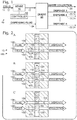
- a cell-containing solution 146 flows through a sample channel 148 arranged substantially parallel to a dispensing channel 150 containing a pressurized dispensing fluid 152.
- the respective liquids generally flow in the same direction as indicated by the arrows in the drawings.
- a connecting channel 154 fluidly connects sample channel 148 to dispensing channel 150.
- a sensing region 156 is disposed in sample channel 148 upstream of the connection between channel 148 and channel 154.
- connecting channel 154 is substantially perpendicular to channels 148 and 150. However, other transverse orientations may be suitable.
- This example describes a parallel channel paddle diverter suitable for use in an on-demand cell dispensing system 10; see Fig. 7 .
- Fig. 7 shows an exemplary diverter mechanism 200 for use in system 10 in a plan view.
- a cell-containing solution 202 flows through a sample channel 204 arranged substantially parallel to a dispensing channel 206 containing a dispensing fluid 208.
- the respective liquids generally flow in the same direction as indicated by the arrows in the drawings.
- a connecting channel 210 selectively connects sample channel 204 to dispensing channel 206 depending on the position of a rotary paddle 212.
- a sensing region 214 is disposed in sample channel 204 upstream of the connection between channel 204 and channel 210.
- Fig. 8 shows an exemplary diverter mechanism 230 for use in system 10 in a plan view.
- a cell-containing solution 232 flows through a sample channel 234 arranged substantially parallel to a dispensing channel 236 containing a dispensing fluid 238.
- the respective liquids generally flow in the same direction as indicated by the arrows in the drawings.
- a connecting channel 240 connects sample channel 234 to dispensing channel 236.
- a sensing region 242 is disposed in sample channel 234 upstream of the connection between channel 234 and channel 240.
- chamber 248 may be depressurized to reset diverter 230 for a subsequent diversion event.
- a second sensing region may be disposed downstream of the diverter in dispensing channel 236 to confirm that the particle was indeed diverted successfully.
- the diverter mechanism urges particles in desired directions using DEP.
- Multiple electrodes 274 adjacent to sample channel 264 are configured to create non-uniform electrical fields across the channel. Because of the DEP effect, these fields will exert a net force on a neutral body such as a cell, causing the body to move transversely within the channel. Accordingly, the electrodes are configured to generate a first field 276 such that all passing particles are moved to a near side 278 of the sample channel as shown in Fig. 9A .
- the controller causes a temporary second field 280 to be generated, thereby moving that particle to an opposite side 282 of the channel, as shown in Fig. 9B .
- Channels 264, 266, and 270 are configured such that particles on opposite side 282 of the channel are directed through the connecting channel and into the dispensing channel, while particles on near side 278 continue through the sample channel to the waste collection area.
- Figs. 10A and 10B show an exemplary diverter mechanism 300 for use in system 10 in an overhead plan view.
- a cell-containing solution 302 flows through a sample channel 304 arranged transverse to a dispensing channel 306.
- Dispensing channel 306 contains a dispensing fluid 308 pressurized to a greater pressure than solution 302.
- the respective liquids are configured to generally flow in transverse directions as indicated by the arrows in the drawings.
- a sensing region 310 is disposed in sample channel 304 upstream of the connection between channel 304 and channel 306.
- solution 302 is prevented from interacting with fluid 308 by one or more valves such as inlet valve 312 and outlet valve 314.
- Valves 312 and 314 are normally closed, as indicated by the solid circles containing an "X" in Fig. 10A .
- Open valves are indicated by an open phantom circle. This valve position convention is used throughout the drawings.
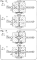
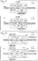
- This example describes a crossed-channel rotary diverter suitable for use in an on-demand cell dispensing system 10; see Figs. 11A and 11B .
- a sensing region 344 may be disposed at any suitable location sufficient to detect a particle of interest 346 and allow rotary diverter 340 to divert the particle by rotating. In some examples, sensing region 344 may be located upstream of the rotary diverter. In this example, sensing region 344 is located at the rotary diverter, and the system is configured to be capable of diverting particle 346 after the particle is detected within diverter channel 342.
- rotary diverter 340 is oriented such that diverter channel 342 is aligned with and connects the sections of sample channel 334 as shown in Fig. 11A .
- Solution 332 and particles that do not meet the preselected criteria are passed through channel 342 to the collection area.
- the controller causes an actuator to reposition the rotary diverter to align diverter channel 342 with the sections of dispensing channel 336 as shown in Fig. 11B .
- This action causes a bulk of solution 348, along with particle 346, to be placed in line with the flow of dispensing fluid 338 and carried to the dispensing area.
- the controller After a suitable time or upon confirmation that particle 346 has been successfully diverted, the controller causes the actuator to reposition rotary diverter 340 to again align diverter channel 342 with sample channel 334 in preparation for a subsequent diversion event.
- Dispensing channel 366 also includes a branched section 370 in which channel 366 forks into two symmetrical channels 372 and 374, both of which are connected to sample channel 364.
- the respective liquids are configured to generally flow in the transverse directions as indicated by the arrows in the drawings.
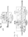
- Dispensing fluid travelling down the second branch then intersects upstream of the blocked particle and flushes (e.g., carries or pushes) it through dispensing channel 398, along with a surrounding portion of the sample-containing carrier fluid.
- one or more valves or other control mechanisms for dispensing fluid may be located off-chip.
- diverter mechanism 384 may include no moving parts, and may be manufactured using conventional injection molding methods.
- Diversion fluid channel 388, branch 386, and dispensing channel 398 may all be substantially aligned directionally at a right angle to sheathed sample channel 392. In other examples, various other angles and arrangements may be suitable.
- Fig. 16 shows another embodiment of this Example 8 in the form of diverter mechanism 430, which is substantially identical to diverter mechanism 400 of Fig. 15 .
- diverter mechanism 430 includes two sensing regions and two dispensing channels, allowing the system to be used as a sorting device.
- a first sensing region 432 is disposed along a sample channel 434 in series with a second sensing region 436.
- the two sensing regions may be configured with different parameters to detect particles having different characteristics.
- the two sensing regions may be configured with different sensing modalities.
- a particle of interest 446 is detected by first sensing region 432 and meets a first set of criteria
- the controller may respond by opening a valve 448 in second dispensing channel 440, thereby diverting particle 446 to dispense through nozzle channel 444.
- a second particle meeting a second set of criteria may be detected by second sensing region 436 and sorted to a different destination by opening a valve 450 in first dispensing channel 438.
- more than two sensing regions and/or more than two dispensing channels may be included.
- a single dispensing channel may be used in conjunction with a movable substrate that is repositioned to sort into different wells or locations based on the detected particle characteristics.
- a single sensing region may be configured to distinguish between particles meeting multiple sets of criteria.
- the controller may then confine and direct particle 464 using any one of a combination of the pressure sources and pathways created by the independent channels 462. Various combinations may be utilized to maximize efficiency, speed, and/or to manipulate particles of differing characteristics. Particle 464 may be dispensed via nozzle 468 or sent to some other destination (not shown).
- Fig. 19 shows another embodiment of this Example 8 including a diverter mechanism 500 substantially identical to diverter mechanism 400.
- This embodiment illustrates one method for hydrodynamically focusing a solution channel 502 by introducing a sheathing liquid.
- the pressurized sheath liquid is introduced at an inlet port 504, and travels via sheathing channels 506 and 508 before intersecting with channel 502 to surround the solution contained in that channel.
- the flow of liquid may enter an unsheathing area.
- side channels 510 and 512 split off the outer flow of liquid from central channel 514, which then includes the original solution minus any dispensed volume. Unsheathing may be desirable to reduce the dilution of collected waste flow.
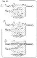
- Figs. 20A-20C show an exemplary diverter mechanism 530 for use in system 10.
- Diverter mechanism 530 includes a pressurized cell-containing solution 532 in a sample channel 534.
- Sample channel 534 is connected via a valved connecting channel 536 with a selectively pressurizable dispensing channel 538, and via a valved collection channel 540 with a collection area.
- a sensing region 542 is disposed adjacent to sample channel 534 upstream of the connection between channel 534 and the other channels.
- a collection valve 544 is located in collection channel 540; a connection valve 546 is located in connecting channel 536; and a pressure source valve 548 is located in dispensing channel 538. As shown in Fig. 20A , collection valve 544 is normally open and the other two valves are normally closed to cause solution 532 to flow to the collection area.
- the controller When a particle of interest 550 is detected in sensing region 542, the controller responds by closing collection valve 544 and opening connection valve 546 to open a path to dispensing channel 538 as shown in Fig. 20B . Shortly thereafter, pressure source valve 548 is opened as shown in Fig. 20C to pressurize channel 538 and flush particle 550 to the dispensing area. Connection valve 546 is closed at the same time to prevent backflow toward the sample channel and collection area. After a suitable delay, or upon confirmation that particle 550 was in fact diverted, the three valves are repositioned as needed to their original states in preparation for a subsequent diversion event.
- Figs. 21A-21B show an exemplary diverter mechanism 560 for use in system 10.
- Diverter mechanism 560 is similar to diverter mechanism 530. However, in this embodiment, four valves are used rather than three. This avoids the situation of the previous embodiment in which the connection valve had to be closed to prevent backflow. Here, the four valves are operated in pairs to isolate and flush a particle.
- valves 566 and 568 in sample channel 562 are normally open, and valves 574 and 576 in the dispensing channels are normally closed as shown in Fig. 21A .
- the controller closes valves 566 and 568 to isolate the particle and opens valves 574 and 576 to flush the particle through dispensing fluid outlet channel 572 as shown in Fig. 21B .
- Figs. 22A and 22B show an exemplary diverter mechanism 600 for use in system 10.
- Diverter mechanism 600 includes a sample channel 602 intersected by sheath flow channels 604 and 606 similar to those described above with respect to Fig. 18 .
- a particle of interest 608 detected at a sensing region 610 is diverted by simply closing off a collection fork 612 of channel 602 to redirect the particle to a dispensing fork 614 of channel 602 as shown in Fig. 22B .
- No additional pressure source in the form of dispensing fluid is used.
- a valve 616 is used to close off collection fork 612.
- a valve may be included in the dispensing fork.
- a toggle valve may be used to selectively close and open the two forks simultaneously.
- Fig. 23 is a schematic diagram showing an illustrative system 700 which is an example of system 10.
- System 700 includes a microfluidics chip 702 on which is located a system including the channels and one or more diverter mechanisms described above.
- Various devices such as valves, sliders, vacuum chambers, and other components that may be located on chip 702 are caused to operate by actuators 704 such as solenoid valves.
- actuators 704 are in turn activated by switches 706 controlled through an input/output (I/O) system 708 by a processor 710.
- Processor 710 may include a microprocessor such as the processor of a typical personal computer or similar device, and may be in communication with a memory or storage device containing instructions for the processor to carry out.
- the controller described above may include the combination of processor 710 and the storage device.
- Processor 710 receives input from sensors 712, such as a camera system or other detection device used in a sensing region on the chip.
- Chip 702 may be mounted on or associated with an X-Y stage 714 such that the chip or a substrate onto which the chip dispenses particles can be precisely located and repositioned as desired.
Landscapes
- Chemical & Material Sciences (AREA)
- Health & Medical Sciences (AREA)
- Analytical Chemistry (AREA)
- General Health & Medical Sciences (AREA)
- Physics & Mathematics (AREA)
- Dispersion Chemistry (AREA)
- Life Sciences & Earth Sciences (AREA)
- Clinical Laboratory Science (AREA)
- Chemical Kinetics & Catalysis (AREA)
- Immunology (AREA)
- Biochemistry (AREA)
- Pathology (AREA)
- Hematology (AREA)
- Fluid Mechanics (AREA)
- Organic Chemistry (AREA)
- General Physics & Mathematics (AREA)
- Wood Science & Technology (AREA)
- Engineering & Computer Science (AREA)
- Proteomics, Peptides & Aminoacids (AREA)
- Zoology (AREA)
- Biotechnology (AREA)
- Microbiology (AREA)
- Molecular Biology (AREA)
- Biophysics (AREA)
- Bioinformatics & Cheminformatics (AREA)
- General Engineering & Computer Science (AREA)
- Genetics & Genomics (AREA)
- Apparatus Associated With Microorganisms And Enzymes (AREA)
Claims (12)
- Verfahren zum Isolieren eines Teilchens aus einer Flüssigkeitsprobe (14), wobei das Verfahren umfasst:Strömenlassen einer Flüssigkeitsprobe (14), die ein Teilchen enthält, durch einen Mikrofluidik-Probenkanal (12);Nachweisen eines Merkmals des Teilchens, während es eine Nachweiszone (16) des Probenkanals (12) passiert;Erzeugen eines Ablenkungssignals als Reaktion auf das nachgewiesene Merkmal, das ein oder mehrere ausgewählte Kriterien erfüllt; undAblenken des Teilchens aus dem Probenkanal (12) in einen Auslasskanal (22) durch Lenken eines Ablenkungsfluids (24) in den Probenkanal (12) vor und hinter dem Teilchen als Reaktion auf das Ablenkungssignal, um das Teilchen aus der Probe (14) zu isolieren und das Teilchen in den Auslasskanal (22) zu spülen.
- Verfahren gemäß Anspruch 1, wobei das Ablenkungsfluid (24) unter einem rechten Winkel in den Probenkanal (12) gelenkt wird.
- Verfahren gemäß Anspruch 1 oder 2, wobei das Nachweisen des Merkmals des Teilchens durchgeführt wird, indem man ein optisches Signal aus der Nachweiszone (16) misst.
- Verfahren gemäß Anspruch 1 oder 2, wobei das Nachweisen des Merkmals des Teilchens durchgeführt wird, indem man ein elektrisches Signal aus der Nachweiszone (16) misst.
- Verfahren gemäß einem der Ansprüche 1 bis 4, weiterhin umfassend das Ausgeben des Teilchens aus dem Auslasskanal (22).
- Verfahren gemäß Anspruch 1, wobei das Strömenlassen der Flüssigkeitsprobe (14) durch einen Probenkanal (12) das Zugeben einer Hüllflüssigkeit in den Probenkanal (12) an einer Stelle stromabwärts der Stelle, wo die Flüssigkeitsprobe (14) in den Probenkanal (12) eingeleitet wird, umfasst.
- Verfahren gemäß Anspruch 6, wobei die Hüllflüssigkeit die Flüssigkeitsprobe (14) in die Mitte des Probenkanals (12) hinein abdrängt.
- Verfahren gemäß einem der Ansprüche 1 bis 7, wobei die Flüssigkeitsprobe (14) einen ersten Typ und einen zweiten Typ von Teilchen enthält, wobei das Nachweisen eines Merkmals des Teilchens zwischen dem ersten und dem zweiten Typ von Teilchen unterscheidet und wobei das Teilchen aus dem Probenkanal (12) in den Auslasskanal (22) abgelenkt wird, wenn es sich um den ersten Typ von Teilchen handelt.
- Verfahren gemäß Anspruch 8, weiterhin umfassend das Erzeugen eines zweiten Ablenkungssignals als Reaktion auf das nachgewiesene Merkmal, welches anzeigt, dass es sich bei dem Teilchen um den zweiten Typ handelt, und Ablenken des Teilchens aus dem Probenkanal (12) in einen zweiten Auslasskanal (22) als Reaktion auf das zweite Ablenkungssignal.
- Verfahren gemäß Anspruch 1, wobei das Lenken des Ablenkungsfluids (24) das Lenken des Ablenkungsfluids (24) in den Probenkanal (12) zuerst stromabwärts und dann stromaufwärts des Teilchens umfasst, so dass das Teilchen durch das stromabwärts eingeleitete Ablenkungsfluid (24) blockiert und dann durch das stromaufwärts eingeleitete Ablenkungsfluid (24) in den Auslasskanal (22) gespült wird.
- Verfahren gemäß Anspruch 10, wobei das Lenken des Ablenkungsfluids (24) das Leiten des Ablenkungsfluids (24) durch eine stromabwärts gelegene Abzweigung und eine stromaufwärts gelegene Abzweigung eines Ablenkungsfluidkanals umfasst, wobei die stromabwärts gelegene Abzweigung einen kürzeren Weg zum Probenkanal (12) bildet als die stromaufwärts gelegene Abzweigung.
- Verfahren gemäß Anspruch 11, wobei die stromabwärts gelegene Abzweigung und der Auslasskanal den Probenkanal (12) auf entgegengesetzten Seiten schneiden, so dass die stromabwärts gelegene Abzweigung und der Auslasskanal im Wesentlichen aufeinander ausgerichtet sind.
Applications Claiming Priority (3)
| Application Number | Priority Date | Filing Date | Title |
|---|---|---|---|
| US201361874320P | 2013-09-05 | 2013-09-05 | |
| US201361902664P | 2013-11-11 | 2013-11-11 | |
| PCT/US2014/054403 WO2015035242A1 (en) | 2013-09-05 | 2014-09-05 | On-demand particle dispensing system |
Publications (3)
| Publication Number | Publication Date |
|---|---|
| EP3042178A1 EP3042178A1 (de) | 2016-07-13 |
| EP3042178A4 EP3042178A4 (de) | 2017-04-05 |
| EP3042178B1 true EP3042178B1 (de) | 2019-08-21 |
Family
ID=52583755
Family Applications (2)
| Application Number | Title | Priority Date | Filing Date |
|---|---|---|---|
| EP14841752.0A Not-in-force EP3042178B1 (de) | 2013-09-05 | 2014-09-05 | Verfahren zur isolierung eines partikels aus einer fluidprobe |
| EP14842644.8A Withdrawn EP3041782A4 (de) | 2013-09-05 | 2014-09-05 | Mehrdimensionale hydrodynamische fokussierungskammer |
Family Applications After (1)
| Application Number | Title | Priority Date | Filing Date |
|---|---|---|---|
| EP14842644.8A Withdrawn EP3041782A4 (de) | 2013-09-05 | 2014-09-05 | Mehrdimensionale hydrodynamische fokussierungskammer |
Country Status (4)
| Country | Link |
|---|---|
| US (2) | US9784664B2 (de) |
| EP (2) | EP3042178B1 (de) |
| CN (2) | CN105829238B (de) |
| WO (2) | WO2015035246A1 (de) |
Families Citing this family (36)
| Publication number | Priority date | Publication date | Assignee | Title |
|---|---|---|---|---|
| US11243494B2 (en) | 2002-07-31 | 2022-02-08 | Abs Global, Inc. | Multiple laminar flow-based particle and cellular separation with laser steering |
| US20070166730A1 (en) * | 2006-01-19 | 2007-07-19 | Menon & Associates, Inc. | Magnetic resonance system and method to detect and confirm analytes |
| TWI532530B (zh) * | 2010-10-29 | 2016-05-11 | 萬國商業機器公司 | 具有浸入通道之多層微流體探針頭及其製造方法 |
| US10908066B2 (en) | 2010-11-16 | 2021-02-02 | 1087 Systems, Inc. | Use of vibrational spectroscopy for microfluidic liquid measurement |
| US8961904B2 (en) | 2013-07-16 | 2015-02-24 | Premium Genetics (Uk) Ltd. | Microfluidic chip |
| US10343165B2 (en) | 2013-09-05 | 2019-07-09 | Bio-Rad Laboratories, Inc. | On-demand particle dispensing system |
| US11796449B2 (en) | 2013-10-30 | 2023-10-24 | Abs Global, Inc. | Microfluidic system and method with focused energy apparatus |
| US10525464B2 (en) | 2014-09-02 | 2020-01-07 | Bio-Rad Laboratories, Inc. | Microscale fluidic devices and components having a fluid retention groove |
| WO2016050837A1 (en) * | 2014-09-30 | 2016-04-07 | Foss Analytical A/S | Method, device and system for hydrodynamic flow focusing |
| US10180388B2 (en) | 2015-02-19 | 2019-01-15 | 1087 Systems, Inc. | Scanning infrared measurement system |
| US11110456B2 (en) | 2016-07-12 | 2021-09-07 | Hewlett-Packard Development Company, L.P. | Bead packing in microfluidic channels |
| US11097272B2 (en) * | 2016-07-26 | 2021-08-24 | Hewlett-Packard Development Company, L.P. | Microfluidic apparatuses for fluid movement control |
| EP3427040B1 (de) * | 2016-07-26 | 2023-08-30 | Hewlett-Packard Development Company, L.P. | Mikrofluidische vorrichtungen |
| WO2018022025A1 (en) | 2016-07-26 | 2018-02-01 | Hewlett-Packard Development Company, L.P. | Microfluidic apparatuses |
| AU2017323502B2 (en) * | 2016-09-12 | 2022-04-21 | Abs Global, Inc. | Method and system for hydrophobic coating of microfluidic chips |
| WO2018199874A1 (en) | 2017-04-23 | 2018-11-01 | Hewlett-Packard Development Company, L.P. | Particle separation |
| WO2018226240A1 (en) | 2017-06-09 | 2018-12-13 | Hewlett-Packard Development Company, L.P. | Porated cell ejection devices |
| WO2019017875A1 (en) * | 2017-07-17 | 2019-01-24 | Hewlett-Packard Development Company, L.P. | DIELECTROPHORESIS SEPARATORS WITH CELL EJECTION DEVICES |
| JP7254806B2 (ja) * | 2017-08-22 | 2023-04-10 | エレジェン コーポレーション | マイクロ流体デバイスの位置トラッキングおよび符号化 |
| US12429412B2 (en) * | 2017-10-25 | 2025-09-30 | Government Of The United States Of America, As Represented By The Secretary Of Commerce | Serial flow cytometer |
| KR20200138352A (ko) | 2018-04-03 | 2020-12-09 | 휴렛-팩커드 디벨롭먼트 컴퍼니, 엘.피. | 상이한 크기의 세포를 운반하는 미세유체 채널 |
| US11331670B2 (en) | 2018-05-23 | 2022-05-17 | Abs Global, Inc. | Systems and methods for particle focusing in microchannels |
| US11428692B2 (en) | 2018-07-11 | 2022-08-30 | Visiongate, Inc. | Specimen enrichment for optical tomography cell analysis |
| EP3899489B1 (de) | 2018-12-21 | 2025-04-09 | ABS Global, Inc. | System und verfahren zur identifizierung einer subpopulation |
| EP3955735B1 (de) | 2019-04-18 | 2024-05-22 | ABS Global, Inc. | System und verfahren zur kontinuierlichen zugabe eines kryoprotektivums |
| US11780227B2 (en) | 2019-06-25 | 2023-10-10 | Hewlett-Packard Development Company, L.P. | Molded structures with channels |
| WO2021072306A1 (en) | 2019-10-10 | 2021-04-15 | 1859, Inc. | Methods and systems for microfluidic screening |
| EP4063827A4 (de) * | 2019-11-20 | 2023-01-04 | Sony Group Corporation | Mikrochip, probenisolationskit und vorrichtung zur isolation von mikropartikeln |
| US11628439B2 (en) | 2020-01-13 | 2023-04-18 | Abs Global, Inc. | Single-sheath microfluidic chip |
| MX2022008652A (es) * | 2020-01-14 | 2022-10-07 | Foss Analytical As | Dispositivo de enfoque hidrodinamico. |
| JP7477378B2 (ja) | 2020-06-19 | 2024-05-01 | シスメックス株式会社 | 粒子ソーター、粒子分取方法およびマイクロ流路カートリッジ |
| WO2022087299A1 (en) | 2020-10-21 | 2022-04-28 | Abs Global, Inc. | Methods and systems for processing genetic samples to determine identity or detect contamination |
| US12135270B2 (en) | 2020-11-23 | 2024-11-05 | Abs Global, Inc. | Modular flow cytometry systems and methods of processing samples |
| USD1118965S1 (en) | 2021-11-12 | 2026-03-17 | Abs Global, Inc. | Flow cytometry device |
| CN116408165B (zh) * | 2022-01-07 | 2026-03-24 | 香港大学 | 用于颗粒尺寸不敏感的高通量单流颗粒聚焦的系统和方法 |
| EP4679059A1 (de) * | 2023-03-07 | 2026-01-14 | Sony Group Corporation | Biopartikelsortiersystem, biopartikelsortierverfahren und chip zur biopartikelsortierung |
Family Cites Families (28)
| Publication number | Priority date | Publication date | Assignee | Title |
|---|---|---|---|---|
| JPH0679682B2 (ja) | 1983-10-31 | 1994-10-12 | ブリティッシュ・テクノロジー・グループ・リミテッド | 液体媒質中の粒状物質の分離方法及び装置 |
| EP0177718B1 (de) | 1984-09-11 | 1989-12-06 | Partec AG | Verfahren und Vorrichtung zur Sortierung von mikroskopischen Partikeln |
| DE19520298A1 (de) * | 1995-06-02 | 1996-12-05 | Bayer Ag | Sortiervorrichtung für biologische Zellen oder Viren |
| US5808737A (en) * | 1996-02-29 | 1998-09-15 | Sienna Biotech, Inc. | Pre-analysis chamber for a flow particle analyzer |
| US6540895B1 (en) | 1997-09-23 | 2003-04-01 | California Institute Of Technology | Microfabricated cell sorter for chemical and biological materials |
| CA2341231C (en) * | 1998-08-21 | 2003-10-21 | Union Biometrica, Inc. | Instrument for selecting and depositing multicellular organisms and other large objects |
| US7242474B2 (en) * | 2004-07-27 | 2007-07-10 | Cox James A | Cytometer having fluid core stream position control |
| AU2002211389A1 (en) | 2000-10-03 | 2002-04-15 | California Institute Of Technology | Microfluidic devices and methods of use |
| US20030027225A1 (en) | 2001-07-13 | 2003-02-06 | Caliper Technologies Corp. | Microfluidic devices and systems for separating components of a mixture |
| AU2002318269A1 (en) * | 2001-07-18 | 2003-03-03 | The Regents Of The University Of Michigan | Gas-focusing flow cytometer cell and flow cytometer detection system with waveguide optics |
| US6877528B2 (en) | 2002-04-17 | 2005-04-12 | Cytonome, Inc. | Microfluidic system including a bubble valve for regulating fluid flow through a microchannel |
| BRPI0408857B1 (pt) * | 2003-03-28 | 2018-09-11 | Inguran Llc | aparelho, métodos e processos para separar partículas e para prover esperma de animal separado por sexo |
| US7311476B2 (en) * | 2003-10-30 | 2007-12-25 | Cytonome, Inc. | Multilayer hydrodynamic sheath flow structure |
| US7389879B2 (en) * | 2004-01-21 | 2008-06-24 | Hewlett-Packard Development Company, L.P. | Sorting particles |
| US20080213821A1 (en) | 2004-05-06 | 2008-09-04 | Nanyang Technological University | Microfluidic Cell Sorter System |
| WO2010144814A2 (en) | 2009-06-13 | 2010-12-16 | Arryx, Inc. | Particle sorting using fluid streams |
| CN101253401B (zh) * | 2005-07-01 | 2013-01-02 | 霍尼韦尔国际公司 | 带三维流体动力学集中的模制标本盒 |
| JP4995197B2 (ja) | 2005-07-01 | 2012-08-08 | ハネウェル・インターナショナル・インコーポレーテッド | 3d流体力学的集束を有する成形カートリッジ |
| GB0802084D0 (en) * | 2008-02-05 | 2008-03-12 | Univ Dublin City | Microfluidic device for assessing cell surface interactions |
| CN102124259B (zh) * | 2008-05-16 | 2015-12-16 | 哈佛大学 | 在包含微流体系统的流体系统中的阀和其它流动控制 |
| UA102854C2 (ru) | 2008-06-30 | 2013-08-27 | Микробикс Байосистемз Инк. | Способ и устройство для сортирования клеток |
| JP2010038866A (ja) * | 2008-08-08 | 2010-02-18 | Sony Corp | マイクロチップ、微小粒子分取装置及び送流方法 |
| JP2010252785A (ja) * | 2009-03-31 | 2010-11-11 | Kanagawa Acad Of Sci & Technol | 細胞濃縮分離装置 |
| CN102459565A (zh) | 2009-06-02 | 2012-05-16 | 尹特根埃克斯有限公司 | 具有隔膜阀的流控设备 |
| CN104330346B (zh) * | 2009-12-04 | 2017-04-12 | 生命技术公司 | 用于声学流式细胞计量术的方法 |
| CN102019277B (zh) * | 2010-10-29 | 2013-05-22 | 北京惟馨雨生物科技有限公司 | 一种用于细胞和颗粒分离的分选仪及分选方法 |
| US20120181460A1 (en) | 2011-01-14 | 2012-07-19 | Integenx Inc. | Valves with Hydraulic Actuation System |
| US8871500B2 (en) | 2011-01-21 | 2014-10-28 | Innovative Micro Technology | MEMS particle sorting actuator and method of manufacturing |
-
2014
- 2014-09-05 EP EP14841752.0A patent/EP3042178B1/de not_active Not-in-force
- 2014-09-05 CN CN201480060260.6A patent/CN105829238B/zh not_active Expired - Fee Related
- 2014-09-05 US US14/479,155 patent/US9784664B2/en not_active Expired - Fee Related
- 2014-09-05 EP EP14842644.8A patent/EP3041782A4/de not_active Withdrawn
- 2014-09-05 CN CN201480060261.0A patent/CN105829865B/zh not_active Expired - Fee Related
- 2014-09-05 WO PCT/US2014/054408 patent/WO2015035246A1/en not_active Ceased
- 2014-09-05 US US14/479,132 patent/US9535000B2/en not_active Expired - Fee Related
- 2014-09-05 WO PCT/US2014/054403 patent/WO2015035242A1/en not_active Ceased
Non-Patent Citations (1)
| Title |
|---|
| None * |
Also Published As
| Publication number | Publication date |
|---|---|
| EP3041782A1 (de) | 2016-07-13 |
| CN105829238A (zh) | 2016-08-03 |
| WO2015035246A1 (en) | 2015-03-12 |
| CN105829238B (zh) | 2017-07-07 |
| US9535000B2 (en) | 2017-01-03 |
| CN105829865B (zh) | 2018-12-04 |
| EP3042178A4 (de) | 2017-04-05 |
| WO2015035242A1 (en) | 2015-03-12 |
| US20150064694A1 (en) | 2015-03-05 |
| US20150093743A1 (en) | 2015-04-02 |
| EP3042178A1 (de) | 2016-07-13 |
| EP3041782A4 (de) | 2017-08-23 |
| CN105829865A (zh) | 2016-08-03 |
| US9784664B2 (en) | 2017-10-10 |
Similar Documents
| Publication | Publication Date | Title |
|---|---|---|
| EP3042178B1 (de) | Verfahren zur isolierung eines partikels aus einer fluidprobe | |
| US10343165B2 (en) | On-demand particle dispensing system | |
| JP5241678B2 (ja) | 微小流体粒子分析システム | |
| CN104350374B (zh) | 用于使用微流体的多个单细胞捕获和处理的方法、系统和设备 | |
| US7312085B2 (en) | Microfluidic particle-analysis systems | |
| HK1191669A (en) | Microfluidic particle-analysis systems |
Legal Events
| Date | Code | Title | Description |
|---|---|---|---|
| PUAI | Public reference made under article 153(3) epc to a published international application that has entered the european phase |
Free format text: ORIGINAL CODE: 0009012 |
|
| 17P | Request for examination filed |
Effective date: 20160308 |
|
| AK | Designated contracting states |
Kind code of ref document: A1 Designated state(s): AL AT BE BG CH CY CZ DE DK EE ES FI FR GB GR HR HU IE IS IT LI LT LU LV MC MK MT NL NO PL PT RO RS SE SI SK SM TR |
|
| AX | Request for extension of the european patent |
Extension state: BA ME |
|
| DAX | Request for extension of the european patent (deleted) | ||
| A4 | Supplementary search report drawn up and despatched |
Effective date: 20170306 |
|
| RIC1 | Information provided on ipc code assigned before grant |
Ipc: B01L 3/00 20060101ALI20170228BHEP Ipc: G01N 15/10 20060101AFI20170228BHEP |
|
| STAA | Information on the status of an ep patent application or granted ep patent |
Free format text: STATUS: EXAMINATION IS IN PROGRESS |
|
| 17Q | First examination report despatched |
Effective date: 20180808 |
|
| GRAP | Despatch of communication of intention to grant a patent |
Free format text: ORIGINAL CODE: EPIDOSNIGR1 |
|
| STAA | Information on the status of an ep patent application or granted ep patent |
Free format text: STATUS: GRANT OF PATENT IS INTENDED |
|
| INTG | Intention to grant announced |
Effective date: 20190322 |
|
| GRAS | Grant fee paid |
Free format text: ORIGINAL CODE: EPIDOSNIGR3 |
|
| GRAA | (expected) grant |
Free format text: ORIGINAL CODE: 0009210 |
|
| STAA | Information on the status of an ep patent application or granted ep patent |
Free format text: STATUS: THE PATENT HAS BEEN GRANTED |
|
| AK | Designated contracting states |
Kind code of ref document: B1 Designated state(s): AL AT BE BG CH CY CZ DE DK EE ES FI FR GB GR HR HU IE IS IT LI LT LU LV MC MK MT NL NO PL PT RO RS SE SI SK SM TR |
|
| REG | Reference to a national code |
Ref country code: GB Ref legal event code: FG4D |
|
| REG | Reference to a national code |
Ref country code: CH Ref legal event code: EP |
|
| REG | Reference to a national code |
Ref country code: DE Ref legal event code: R096 Ref document number: 602014052276 Country of ref document: DE |
|
| REG | Reference to a national code |
Ref country code: AT Ref legal event code: REF Ref document number: 1170294 Country of ref document: AT Kind code of ref document: T Effective date: 20190915 |
|
| REG | Reference to a national code |
Ref country code: IE Ref legal event code: FG4D |
|
| REG | Reference to a national code |
Ref country code: LT Ref legal event code: MG4D |
|
| REG | Reference to a national code |
Ref country code: NL Ref legal event code: MP Effective date: 20190821 |
|
| PG25 | Lapsed in a contracting state [announced via postgrant information from national office to epo] |
Ref country code: PT Free format text: LAPSE BECAUSE OF FAILURE TO SUBMIT A TRANSLATION OF THE DESCRIPTION OR TO PAY THE FEE WITHIN THE PRESCRIBED TIME-LIMIT Effective date: 20191223 Ref country code: NO Free format text: LAPSE BECAUSE OF FAILURE TO SUBMIT A TRANSLATION OF THE DESCRIPTION OR TO PAY THE FEE WITHIN THE PRESCRIBED TIME-LIMIT Effective date: 20191121 Ref country code: SE Free format text: LAPSE BECAUSE OF FAILURE TO SUBMIT A TRANSLATION OF THE DESCRIPTION OR TO PAY THE FEE WITHIN THE PRESCRIBED TIME-LIMIT Effective date: 20190821 Ref country code: FI Free format text: LAPSE BECAUSE OF FAILURE TO SUBMIT A TRANSLATION OF THE DESCRIPTION OR TO PAY THE FEE WITHIN THE PRESCRIBED TIME-LIMIT Effective date: 20190821 Ref country code: LT Free format text: LAPSE BECAUSE OF FAILURE TO SUBMIT A TRANSLATION OF THE DESCRIPTION OR TO PAY THE FEE WITHIN THE PRESCRIBED TIME-LIMIT Effective date: 20190821 Ref country code: HR Free format text: LAPSE BECAUSE OF FAILURE TO SUBMIT A TRANSLATION OF THE DESCRIPTION OR TO PAY THE FEE WITHIN THE PRESCRIBED TIME-LIMIT Effective date: 20190821 Ref country code: BG Free format text: LAPSE BECAUSE OF FAILURE TO SUBMIT A TRANSLATION OF THE DESCRIPTION OR TO PAY THE FEE WITHIN THE PRESCRIBED TIME-LIMIT Effective date: 20191121 Ref country code: NL Free format text: LAPSE BECAUSE OF FAILURE TO SUBMIT A TRANSLATION OF THE DESCRIPTION OR TO PAY THE FEE WITHIN THE PRESCRIBED TIME-LIMIT Effective date: 20190821 |
|
| PG25 | Lapsed in a contracting state [announced via postgrant information from national office to epo] |
Ref country code: AL Free format text: LAPSE BECAUSE OF FAILURE TO SUBMIT A TRANSLATION OF THE DESCRIPTION OR TO PAY THE FEE WITHIN THE PRESCRIBED TIME-LIMIT Effective date: 20190821 Ref country code: ES Free format text: LAPSE BECAUSE OF FAILURE TO SUBMIT A TRANSLATION OF THE DESCRIPTION OR TO PAY THE FEE WITHIN THE PRESCRIBED TIME-LIMIT Effective date: 20190821 Ref country code: LV Free format text: LAPSE BECAUSE OF FAILURE TO SUBMIT A TRANSLATION OF THE DESCRIPTION OR TO PAY THE FEE WITHIN THE PRESCRIBED TIME-LIMIT Effective date: 20190821 Ref country code: RS Free format text: LAPSE BECAUSE OF FAILURE TO SUBMIT A TRANSLATION OF THE DESCRIPTION OR TO PAY THE FEE WITHIN THE PRESCRIBED TIME-LIMIT Effective date: 20190821 Ref country code: GR Free format text: LAPSE BECAUSE OF FAILURE TO SUBMIT A TRANSLATION OF THE DESCRIPTION OR TO PAY THE FEE WITHIN THE PRESCRIBED TIME-LIMIT Effective date: 20191122 Ref country code: IS Free format text: LAPSE BECAUSE OF FAILURE TO SUBMIT A TRANSLATION OF THE DESCRIPTION OR TO PAY THE FEE WITHIN THE PRESCRIBED TIME-LIMIT Effective date: 20191221 |
|
| REG | Reference to a national code |
Ref country code: AT Ref legal event code: MK05 Ref document number: 1170294 Country of ref document: AT Kind code of ref document: T Effective date: 20190821 |
|
| PG25 | Lapsed in a contracting state [announced via postgrant information from national office to epo] |
Ref country code: TR Free format text: LAPSE BECAUSE OF FAILURE TO SUBMIT A TRANSLATION OF THE DESCRIPTION OR TO PAY THE FEE WITHIN THE PRESCRIBED TIME-LIMIT Effective date: 20190821 |
|
| PG25 | Lapsed in a contracting state [announced via postgrant information from national office to epo] |
Ref country code: RO Free format text: LAPSE BECAUSE OF FAILURE TO SUBMIT A TRANSLATION OF THE DESCRIPTION OR TO PAY THE FEE WITHIN THE PRESCRIBED TIME-LIMIT Effective date: 20190821 Ref country code: PL Free format text: LAPSE BECAUSE OF FAILURE TO SUBMIT A TRANSLATION OF THE DESCRIPTION OR TO PAY THE FEE WITHIN THE PRESCRIBED TIME-LIMIT Effective date: 20190821 Ref country code: DK Free format text: LAPSE BECAUSE OF FAILURE TO SUBMIT A TRANSLATION OF THE DESCRIPTION OR TO PAY THE FEE WITHIN THE PRESCRIBED TIME-LIMIT Effective date: 20190821 Ref country code: AT Free format text: LAPSE BECAUSE OF FAILURE TO SUBMIT A TRANSLATION OF THE DESCRIPTION OR TO PAY THE FEE WITHIN THE PRESCRIBED TIME-LIMIT Effective date: 20190821 Ref country code: EE Free format text: LAPSE BECAUSE OF FAILURE TO SUBMIT A TRANSLATION OF THE DESCRIPTION OR TO PAY THE FEE WITHIN THE PRESCRIBED TIME-LIMIT Effective date: 20190821 Ref country code: IT Free format text: LAPSE BECAUSE OF FAILURE TO SUBMIT A TRANSLATION OF THE DESCRIPTION OR TO PAY THE FEE WITHIN THE PRESCRIBED TIME-LIMIT Effective date: 20190821 |
|
| PG25 | Lapsed in a contracting state [announced via postgrant information from national office to epo] |
Ref country code: CZ Free format text: LAPSE BECAUSE OF FAILURE TO SUBMIT A TRANSLATION OF THE DESCRIPTION OR TO PAY THE FEE WITHIN THE PRESCRIBED TIME-LIMIT Effective date: 20190821 Ref country code: SM Free format text: LAPSE BECAUSE OF FAILURE TO SUBMIT A TRANSLATION OF THE DESCRIPTION OR TO PAY THE FEE WITHIN THE PRESCRIBED TIME-LIMIT Effective date: 20190821 Ref country code: SK Free format text: LAPSE BECAUSE OF FAILURE TO SUBMIT A TRANSLATION OF THE DESCRIPTION OR TO PAY THE FEE WITHIN THE PRESCRIBED TIME-LIMIT Effective date: 20190821 Ref country code: MC Free format text: LAPSE BECAUSE OF FAILURE TO SUBMIT A TRANSLATION OF THE DESCRIPTION OR TO PAY THE FEE WITHIN THE PRESCRIBED TIME-LIMIT Effective date: 20190821 Ref country code: IS Free format text: LAPSE BECAUSE OF FAILURE TO SUBMIT A TRANSLATION OF THE DESCRIPTION OR TO PAY THE FEE WITHIN THE PRESCRIBED TIME-LIMIT Effective date: 20200224 |
|
| REG | Reference to a national code |
Ref country code: CH Ref legal event code: PL |
|
| REG | Reference to a national code |
Ref country code: DE Ref legal event code: R097 Ref document number: 602014052276 Country of ref document: DE |
|
| PLBE | No opposition filed within time limit |
Free format text: ORIGINAL CODE: 0009261 |
|
| STAA | Information on the status of an ep patent application or granted ep patent |
Free format text: STATUS: NO OPPOSITION FILED WITHIN TIME LIMIT |
|
| PG2D | Information on lapse in contracting state deleted |
Ref country code: IS |
|
| PG25 | Lapsed in a contracting state [announced via postgrant information from national office to epo] |
Ref country code: CH Free format text: LAPSE BECAUSE OF NON-PAYMENT OF DUE FEES Effective date: 20190930 Ref country code: LI Free format text: LAPSE BECAUSE OF NON-PAYMENT OF DUE FEES Effective date: 20190930 Ref country code: LU Free format text: LAPSE BECAUSE OF NON-PAYMENT OF DUE FEES Effective date: 20190905 Ref country code: IE Free format text: LAPSE BECAUSE OF NON-PAYMENT OF DUE FEES Effective date: 20190905 |
|
| 26N | No opposition filed |
Effective date: 20200603 |
|
| REG | Reference to a national code |
Ref country code: BE Ref legal event code: MM Effective date: 20190930 |
|
| PG25 | Lapsed in a contracting state [announced via postgrant information from national office to epo] |
Ref country code: BE Free format text: LAPSE BECAUSE OF NON-PAYMENT OF DUE FEES Effective date: 20190930 Ref country code: SI Free format text: LAPSE BECAUSE OF FAILURE TO SUBMIT A TRANSLATION OF THE DESCRIPTION OR TO PAY THE FEE WITHIN THE PRESCRIBED TIME-LIMIT Effective date: 20190821 |
|
| PGFP | Annual fee paid to national office [announced via postgrant information from national office to epo] |
Ref country code: GB Payment date: 20200925 Year of fee payment: 7 Ref country code: FR Payment date: 20200925 Year of fee payment: 7 |
|
| PGFP | Annual fee paid to national office [announced via postgrant information from national office to epo] |
Ref country code: DE Payment date: 20201127 Year of fee payment: 7 |
|
| PG25 | Lapsed in a contracting state [announced via postgrant information from national office to epo] |
Ref country code: CY Free format text: LAPSE BECAUSE OF FAILURE TO SUBMIT A TRANSLATION OF THE DESCRIPTION OR TO PAY THE FEE WITHIN THE PRESCRIBED TIME-LIMIT Effective date: 20190821 |
|
| PG25 | Lapsed in a contracting state [announced via postgrant information from national office to epo] |
Ref country code: HU Free format text: LAPSE BECAUSE OF FAILURE TO SUBMIT A TRANSLATION OF THE DESCRIPTION OR TO PAY THE FEE WITHIN THE PRESCRIBED TIME-LIMIT; INVALID AB INITIO Effective date: 20140905 Ref country code: MT Free format text: LAPSE BECAUSE OF FAILURE TO SUBMIT A TRANSLATION OF THE DESCRIPTION OR TO PAY THE FEE WITHIN THE PRESCRIBED TIME-LIMIT Effective date: 20190821 |
|
| REG | Reference to a national code |
Ref country code: DE Ref legal event code: R119 Ref document number: 602014052276 Country of ref document: DE |
|
| GBPC | Gb: european patent ceased through non-payment of renewal fee |
Effective date: 20210905 |
|
| PG25 | Lapsed in a contracting state [announced via postgrant information from national office to epo] |
Ref country code: MK Free format text: LAPSE BECAUSE OF FAILURE TO SUBMIT A TRANSLATION OF THE DESCRIPTION OR TO PAY THE FEE WITHIN THE PRESCRIBED TIME-LIMIT Effective date: 20190821 |
|
| PG25 | Lapsed in a contracting state [announced via postgrant information from national office to epo] |
Ref country code: GB Free format text: LAPSE BECAUSE OF NON-PAYMENT OF DUE FEES Effective date: 20210905 Ref country code: FR Free format text: LAPSE BECAUSE OF NON-PAYMENT OF DUE FEES Effective date: 20210930 Ref country code: DE Free format text: LAPSE BECAUSE OF NON-PAYMENT OF DUE FEES Effective date: 20220401 |
|
| P01 | Opt-out of the competence of the unified patent court (upc) registered |
Effective date: 20230426 |