EP3042702A1 - Roll- und springroboter mit erhöhter fähigkeit zur überwindung von hindernissen - Google Patents
Roll- und springroboter mit erhöhter fähigkeit zur überwindung von hindernissen Download PDFInfo
- Publication number
- EP3042702A1 EP3042702A1 EP15200312.5A EP15200312A EP3042702A1 EP 3042702 A1 EP3042702 A1 EP 3042702A1 EP 15200312 A EP15200312 A EP 15200312A EP 3042702 A1 EP3042702 A1 EP 3042702A1
- Authority
- EP
- European Patent Office
- Prior art keywords
- robot
- wheels
- ground
- tail
- stand
- Prior art date
- Legal status (The legal status is an assumption and is not a legal conclusion. Google has not performed a legal analysis and makes no representation as to the accuracy of the status listed.)
- Withdrawn
Links
- 238000005096 rolling process Methods 0.000 title claims description 3
- 238000005452 bending Methods 0.000 claims description 9
- 230000000694 effects Effects 0.000 claims description 8
- 230000009471 action Effects 0.000 claims description 4
- 230000000284 resting effect Effects 0.000 claims description 4
- 230000008859 change Effects 0.000 claims description 2
- 230000007704 transition Effects 0.000 claims description 2
- 238000006073 displacement reaction Methods 0.000 description 4
- 230000009191 jumping Effects 0.000 description 4
- 208000031968 Cadaver Diseases 0.000 description 3
- 230000001133 acceleration Effects 0.000 description 3
- 230000006835 compression Effects 0.000 description 3
- 238000007906 compression Methods 0.000 description 3
- 230000004048 modification Effects 0.000 description 3
- 238000012986 modification Methods 0.000 description 3
- 241000909536 Gobiesocidae Species 0.000 description 2
- 238000006243 chemical reaction Methods 0.000 description 2
- 230000005484 gravity Effects 0.000 description 2
- 230000003287 optical effect Effects 0.000 description 2
- 238000005381 potential energy Methods 0.000 description 2
- 244000007853 Sarothamnus scoparius Species 0.000 description 1
- 240000008042 Zea mays Species 0.000 description 1
- 230000005540 biological transmission Effects 0.000 description 1
- 239000000463 material Substances 0.000 description 1
- 230000007246 mechanism Effects 0.000 description 1
- 238000009527 percussion Methods 0.000 description 1
- 239000007779 soft material Substances 0.000 description 1
- 239000002689 soil Substances 0.000 description 1
- 230000001131 transforming effect Effects 0.000 description 1
Images


Classifications
-
- A—HUMAN NECESSITIES
- A63—SPORTS; GAMES; AMUSEMENTS
- A63H—TOYS, e.g. TOPS, DOLLS, HOOPS OR BUILDING BLOCKS
- A63H11/00—Self-movable toy figures
- A63H11/06—Jumping toys
-
- B—PERFORMING OPERATIONS; TRANSPORTING
- B62—LAND VEHICLES FOR TRAVELLING OTHERWISE THAN ON RAILS
- B62D—MOTOR VEHICLES; TRAILERS
- B62D57/00—Vehicles characterised by having other propulsion or other ground- engaging means than wheels or endless track, alone or in addition to wheels or endless track
- B62D57/02—Vehicles characterised by having other propulsion or other ground- engaging means than wheels or endless track, alone or in addition to wheels or endless track with ground-engaging propulsion means, e.g. walking members
-
- A—HUMAN NECESSITIES
- A63—SPORTS; GAMES; AMUSEMENTS
- A63H—TOYS, e.g. TOPS, DOLLS, HOOPS OR BUILDING BLOCKS
- A63H17/00—Toy vehicles, e.g. with self-drive; ; Cranes, winches or the like; Accessories therefor
- A63H17/004—Stunt-cars, e.g. lifting front wheels, roll-over or invertible cars
-
- A—HUMAN NECESSITIES
- A63—SPORTS; GAMES; AMUSEMENTS
- A63H—TOYS, e.g. TOPS, DOLLS, HOOPS OR BUILDING BLOCKS
- A63H17/00—Toy vehicles, e.g. with self-drive; ; Cranes, winches or the like; Accessories therefor
- A63H17/26—Details; Accessories
- A63H17/262—Chassis; Wheel mountings; Wheels; Axles; Suspensions; Fitting body portions to chassis
-
- A—HUMAN NECESSITIES
- A63—SPORTS; GAMES; AMUSEMENTS
- A63H—TOYS, e.g. TOPS, DOLLS, HOOPS OR BUILDING BLOCKS
- A63H29/00—Drive mechanisms for toys in general
- A63H29/22—Electric drives
-
- A—HUMAN NECESSITIES
- A63—SPORTS; GAMES; AMUSEMENTS
- A63H—TOYS, e.g. TOPS, DOLLS, HOOPS OR BUILDING BLOCKS
- A63H33/00—Other toys
- A63H33/005—Motorised rolling toys
-
- Y—GENERAL TAGGING OF NEW TECHNOLOGICAL DEVELOPMENTS; GENERAL TAGGING OF CROSS-SECTIONAL TECHNOLOGIES SPANNING OVER SEVERAL SECTIONS OF THE IPC; TECHNICAL SUBJECTS COVERED BY FORMER USPC CROSS-REFERENCE ART COLLECTIONS [XRACs] AND DIGESTS
- Y10—TECHNICAL SUBJECTS COVERED BY FORMER USPC
- Y10S—TECHNICAL SUBJECTS COVERED BY FORMER USPC CROSS-REFERENCE ART COLLECTIONS [XRACs] AND DIGESTS
- Y10S901/00—Robots
- Y10S901/01—Mobile robot
Definitions
- the invention relates to a robot and jumper with a pair of wheels arranged on either side of a body of the robot.
- Such a type of robot is for example described in the JP 2011/41696 A (Barse ) as well as in the EP 2 862 606 A1 (published on 22.04.2015 ), corresponding to the product marketed under the name "Jumping Sumo” by Parrot SA, Paris, France.
- the body of the robot comprises a frame or plate connected to the wheels and a sliding part guided on slides, with a spring interposed between the plate and the sliding part.
- a motor moves the sliding piece closer to the edge, which has the effect of gradually compressing the spring and thus accumulating elastic potential energy.
- the assembly is held in this position by a locking system, which can be released to suddenly release the spring and project the robot above the ground by transforming the potential energy of the spring into kinetic energy, the percussion of the sliding element against the ground producing, by reaction, the desired bouncing effect.
- the height of the jump can be adjusted by a variable compression of the spring, in order to deliver more or less energy at the time of the jump.
- the purpose of the present invention is, while maintaining this basic structure and this jump function, to improve the robot to add obstacle assistance features, especially when used in "off-road” , or to cross for example steps, curbs, etc., and this with a minimum of additional material means added to the basic structure.
- the sliding piece has a protruding distal end supporting a contact pad such that in the closed position the contact pad is located near the perimeter of the wheels, and that the expansion of the sliding part is transmitted by the contact pad.
- the robot further comprises a tail stand extending in a vertical plane and secured to the body of the robot at an attachment point located at a distance from the slider and in a region opposite the ground relative to at the main direction of the lookout.
- the tail stand forms at its distal end an alternating ground contact point in an area beyond the circumference of the wheels.
- this tail stand is at least partly elastically deformable in bending so as to allow a constraint bringing the contact pad closer to or away from the contact surface on the ground.
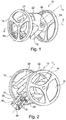
- FIGS 1, 2 and 3 illustrate a robot of known type, such as that described in EP 2 862 606 A1 supra.
- the reference 10 generally designates the robot, which comprises a plate 12 supported by two wheels 14.
- the wheels 14 are mounted on the plate 12 to pivot about a common axis D, and they are driven independently by own electric motors (not shown), controlled by appropriate circuits allowing the robot, according to the direction and the speed of rotation of the wheels, to advance in a straight line, to back off, to turn on itself or while making a turn , etc., these different evolutions being controlled by the user by means of a suitable remote control.
- the plate 12 extends in a main direction ⁇ , perpendicular to the axis D of the wheels and supports a sliding part 16 displaceable in translation parallel to the axis ⁇ under the effect of a suitable motor, driven by the control circuits of the robot.
- This sliding room 16 comprises, for example, two parallel rods 18 guided by these respective cylinders 20 integral with the plate 12, with interposition between the rods 18 and the cylinders 20 of one or more helical springs (not visible in the figures) serving as storage means of energy, with compression of the spring when the slider 16 is moved closer to the plate 12, and inversely restitution to the sliding part 16 of the energy stored by these springs when the slider 16 is released to a deployed position of the set / slider.
- This mechanism is described in particular in EP 2,952,236 A1 (published on 09.12.2015 ).
- the distal end of this piece protrudes beyond the circumference of the wheels 14, and can come into contact with the ground.
- This distal end comprises for this purpose an insert or a surface forming a contact pad 36, capable of forming a ground support point for the robot (point referenced A 2 on the Figures 3 (a) and (b) ).
- the robot may also be provided with one or more optical devices 38 ( Figure 1 ) such as a camera or lighting, whose optical axis ⁇ forms a fixed angle with respect to the main direction ⁇ of the lookout and the body of the robot integral with this lookout.
- This device makes it possible, for example, when the robot moves while driving, to illuminate the front of the robot and / or to capture a video image of the maneuvering area, seen from the robot.
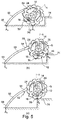
- FIGS 3 (a) and (b) illustrate the robot in two positions, hereinafter referred to as “deployed” 40 and “tightened” 40 'corresponding to the two extreme positions of the sliding part 16 in its displacement guided in translation relative to the plate 12.
- the robot rests on the ground 42 by three points of support: at 44, in contact with the wheels (point A 1 ) with the ground, and by the pad contact 36 at the distal end of the slider 16 (point A 2 ).
- the sliding part 16 forms a telescopic assembly with the lug 12, and it can therefore move in translation between the deployed position 40 ( Figure 3 (a) ) and the tight position 40 '( Figure 3 (b) ) under the action of a motor driven specifically to ensure this translation.
- the deployed position of the Figure 3 (a) especially allows taxiing, rotations, etc.
- the displacement of the sliding part 16 towards the constricted position produces a displacement of the bearing point on the ground A 2 by the shoe 36 and, correspondingly, a modification of the inclination of the axis ⁇ of the edge, and therefore of the inclination of the robot.
- the narrow position of the Figure 3 (b) constitutes the preparatory position for the jump, which will occur by sudden release of the energy of the previously compressed springs, this energy being transmitted via the shoe 36, by inertia and reaction of the ground, to the body 22 of the robot to cause the jump of the latter .
- the robot is provided with wheels 14 which are notched wheels, that is to say provided at their periphery, on the tread, reliefs, notches or crampons 48 or other similar means (crampons attached or monoblock with the wheel, deep carvings, etc.) providing high adhesion on uneven floors, for example as illustrated in Figures 5 (b) and (c) on the edge of a step, or on natural, stony ground, with branches, & c. by minimizing the risk of skidding of the robot.
- An alternative to toothed wheels is, in an equivalent manner, to achieve these wheels in a very soft material, which can marry by its deformation the irregularities of the soil on which the robot evolves.
- the robot is provided with a tail stand 50 secured to the body of the robot.
- this Crutch 50 is formed of an elongated rigid element 52 connected to the robot body by an elastically deformable member 54 such as a coil spring or an elastic sleeve.
- the distal end 56 of the tail stand 50 is intended to form an alternative fulcrum for the robot body.
- the dimensions and shape of the tail stand are chosen so that this end 56 is located beyond the periphery of the wheels, for example at a distance from the axis of rotation between typically 1 and 3 times the diameter of the wheels.
- the tail stand 50 is secured to the body (by the elastic element 54 in the example shown) at an attachment point 58 located in radial direction at a distance from the slider 16 and in a region of the robot body located opposite the ground relative to the main direction ⁇ of the edge, in particular on the protruding protrusion 24 in the upper part of the robot body, in the inner vicinity of the periphery of the wheels.
- the tail stand 50 which extends in a vertical plane, is a flexible stand due to the elastic member 54 which connects the elongated rigid member at the point of attachment 58 to the body of the robot. More specifically, this flexibility must allow flexural deformation allowing, under stress, a distance or approaching the contact pad (36) relative to the contact surface on the ground.
- the general configuration of the tail stand and its dimensions are such that when the slider is in the extended position (configuration of the Figure 4 (a) , corresponding itself to the configuration of the Figure 3 (a) ), the only support points that hold the robot and support its weight in this case remain the sliding piece (in A2) and the wheels (in A1). It may possibly remain, as in the example of the figure, an interval between the surface of the ground and the distal end 56 of the tail crutch 50, but in any case even if this end 56 touches the ground it does not does not form a true fulcrum when the sliding part is deployed, because of the flexibility of the stand 50.
- the dimensions and the shape of the tail stand are chosen so that this change of fulcrum during the transition to the tightened position of the sliding part takes place without modification of the general orientation of the axis ⁇ of the lookout, and therefore the axis ⁇ of the robot camera relative to the ground (or with a small modification, because of the weight of the robot and the flexible part, resulting in a slight bending of the stand).
- This will avoid a tilting of the image of the scene captured by this camera, as was the case with the known robot shown Figure 3 , where the passage of the position of the Figure 3 (a) to that of Figure 3 (b) was made with tilting upwards of the axis ⁇ , and therefore of the viewing direction ⁇ of the camera.
- the tail stand 50 advantageously has a curved shape, turning its concavity towards the ground, which allows with a shorter stand to better control the positioning of the body of the robot.
- the function of the end 56 of the tail stand is, mainly, to constitute an alternative support point for the robot under conditions that will be discussed below. But this end can also be used, in a subsidiary manner, for fixing an accessory providing additional functionality to the robot, for example by mounting a float, a broom, a catapult, quills, etc. either by directly mounting the accessory on the tail stand, or by replacing all or part of the rigid portion 52 of the stand by a replacement element carrying the accessory in question.
- This narrow position can be kept waiting for a subsequent jump, the robot can continue to evolve on the ground with increased stability especially in rough terrain thanks to the studs 48 of the wheels 14 but, especially, the greater distance between the contact points A 1 of the wheels and the third fulcrum, namely the alternative bearing point A 3 , which defines a triangle of support greater than in the previous case.
- the control circuit of the drive motors of the wheels sends to them an acceleration pulse which causes a tilting back of the body of the robot (arrow 64, Figure 3 (c )) resulting in the recoil of the alternative bearing point A 3 (arrow 68) and the deflection (schematized by the arrow 70) of the elastic element 54 of the tail support.
- the acceleration pulse printed to the robot and the bending of the tail stand 50 has the effect of pressing the pad 36 to the ground.
- the control circuit releases the locking means of the sliding part, which has the effect of causing the sudden expansion of this sliding part and the jumping of the robot above from the ground, by the shoe 36 (arrows 72, Figure 4 (d) ).
- the release of the locking means is caused at the appropriate moment by adjustment between the instant of this release (unlocking) and the duration of the acceleration pulse of the wheels. This ensures a jump under the best conditions, with direct and immediate transmission of the energy released at the moment of unlocking.
- the obstacle is a step 74 in front of which the robot presents itself, in the illustrated configuration Figure 5 (a) .
- the wheels 14 of the robot have advanced (arrow 76) and they come into contact with the obstacle 74 and thanks to the studs 48 are hanging a projecting portion of this obstacle, for example the nose of the step 74.
- the robot is then in bearing on the contact points A 5 of the wheels with the obstacle, and the alternative bearing point A 3 which is always in contact with the ground.
- the tail stand 50 Under the effect of the weight of the robot, whose center of gravity G is between the points A 5 and A 3 , the tail stand 50 is placed under elastic stress, with bending of the deformable elastic element 54 (bending schematized by arrow 78).
- the robot can continue its path, the tail crutch 50 ensuring the stability of the moving assembly during this transitional phase.
- the contact face of the shoe 36 turned towards the ground is preferably a rounded, convex face, so as not to catch the obstacle and allow to pass it without inconvenience.
- the illustrated configuration Figure 5 (a) can be a configuration where the robot is stopped, simply facing the obstacle.
Landscapes
- Engineering & Computer Science (AREA)
- Chemical & Material Sciences (AREA)
- Combustion & Propulsion (AREA)
- Transportation (AREA)
- Mechanical Engineering (AREA)
- Manipulator (AREA)
- Toys (AREA)
Applications Claiming Priority (1)
| Application Number | Priority Date | Filing Date | Title |
|---|---|---|---|
| FR1463364A FR3031044A1 (fr) | 2014-12-29 | 2014-12-29 | Robot roulant et sauteur a capacite accrue de franchissement d'obstacle |
Publications (1)
| Publication Number | Publication Date |
|---|---|
| EP3042702A1 true EP3042702A1 (de) | 2016-07-13 |
Family
ID=52988238
Family Applications (1)
| Application Number | Title | Priority Date | Filing Date |
|---|---|---|---|
| EP15200312.5A Withdrawn EP3042702A1 (de) | 2014-12-29 | 2015-12-16 | Roll- und springroboter mit erhöhter fähigkeit zur überwindung von hindernissen |
Country Status (5)
| Country | Link |
|---|---|
| US (1) | US20160184721A1 (de) |
| EP (1) | EP3042702A1 (de) |
| JP (1) | JP2016137240A (de) |
| CN (1) | CN105799802A (de) |
| FR (1) | FR3031044A1 (de) |
Families Citing this family (15)
| Publication number | Priority date | Publication date | Assignee | Title |
|---|---|---|---|---|
| US10058999B2 (en) * | 2016-10-12 | 2018-08-28 | Lunghwa University Of Science And Technology | Wheeled jumping robot |
| CN111514591A (zh) * | 2019-02-01 | 2020-08-11 | 智高实业股份有限公司 | 可转向的爬墙玩具 |
| CN109850025B (zh) * | 2019-02-26 | 2020-09-04 | 浙江大学 | 一种墙面跳跃的单腿机器人机构及控制方法 |
| CN110253593B (zh) * | 2019-06-03 | 2021-07-20 | 北京交通大学 | 具有可变形车架结构的轮式越障机器人 |
| CN111055947A (zh) * | 2019-12-03 | 2020-04-24 | 上海交通大学 | 可折叠轮式变形机器人装置 |
| CN111284582B (zh) * | 2020-03-26 | 2023-11-17 | 行星算力(深圳)科技有限公司 | 一种多功能全地形运输机器人 |
| CN111591373B (zh) * | 2020-06-04 | 2021-04-13 | 崔正筠 | 一种全地形探测小车 |
| CN112223309B (zh) * | 2020-09-30 | 2024-01-12 | 腾讯科技(深圳)有限公司 | 一种控制器、控制方法及机器人 |
| CN112548984B (zh) * | 2020-12-10 | 2022-04-12 | 逻腾(杭州)科技有限公司 | 一种带伸缩臂的滚动越障机器人 |
| CN113002244A (zh) * | 2021-03-16 | 2021-06-22 | 重庆大学 | 深空探测弹跳机器人 |
| CN113086101B (zh) * | 2021-03-29 | 2022-03-11 | 哈尔滨工业大学 | 一种水面跳跃滑行机器人 |
| CN113443041B (zh) * | 2021-07-29 | 2022-05-17 | 山东大学 | 复合腿足机构及3-ups并联轮足复合弹跳机器人 |
| CN116215691B (zh) * | 2023-03-16 | 2024-10-18 | 吉林大学 | 一种月面车轮脱困仿生腿式机构 |
| CN117262053A (zh) * | 2023-09-15 | 2023-12-22 | 山东大学 | 一种基于张拉整体结构的机器人、复合机器人及工作方法 |
| CN118034362A (zh) * | 2024-01-30 | 2024-05-14 | 深圳市优必选科技股份有限公司 | 机器人控制方法、装置、计算机可读存储介质及机器人 |
Citations (6)
| Publication number | Priority date | Publication date | Assignee | Title |
|---|---|---|---|---|
| US3703784A (en) * | 1972-03-16 | 1972-11-28 | Voorhis F Wigal | Multiple jumping device |
| US20080230285A1 (en) * | 2006-12-06 | 2008-09-25 | The Regents Of The University Of California | Multimodal agile robots |
| JP2011041696A (ja) | 2009-08-21 | 2011-03-03 | Ushida Hiroshi | 跳躍体 |
| CN203525303U (zh) * | 2013-10-21 | 2014-04-09 | 胡妍琪 | 一种新型弹跳玩具车 |
| EP2862606A1 (de) | 2013-10-18 | 2015-04-22 | Parrot | Rollendes und hüpfendes Spielzeug mit mehreren Positionen |
| EP2952236A1 (de) | 2014-06-04 | 2015-12-09 | Parrot | Federbelasteter spann-/entspannmechanismus, und hüpfspielzeug, das diesen mechanismus umfasst |
Family Cites Families (1)
| Publication number | Priority date | Publication date | Assignee | Title |
|---|---|---|---|---|
| KR101023060B1 (ko) * | 2008-09-12 | 2011-03-24 | (주)컨벡스 | 점프 기능을 가지는 이동 로봇 |
-
2014
- 2014-12-29 FR FR1463364A patent/FR3031044A1/fr not_active Withdrawn
-
2015
- 2015-12-16 EP EP15200312.5A patent/EP3042702A1/de not_active Withdrawn
- 2015-12-28 US US14/979,891 patent/US20160184721A1/en not_active Abandoned
- 2015-12-28 JP JP2015255808A patent/JP2016137240A/ja active Pending
- 2015-12-29 CN CN201511009545.XA patent/CN105799802A/zh active Pending
Patent Citations (6)
| Publication number | Priority date | Publication date | Assignee | Title |
|---|---|---|---|---|
| US3703784A (en) * | 1972-03-16 | 1972-11-28 | Voorhis F Wigal | Multiple jumping device |
| US20080230285A1 (en) * | 2006-12-06 | 2008-09-25 | The Regents Of The University Of California | Multimodal agile robots |
| JP2011041696A (ja) | 2009-08-21 | 2011-03-03 | Ushida Hiroshi | 跳躍体 |
| EP2862606A1 (de) | 2013-10-18 | 2015-04-22 | Parrot | Rollendes und hüpfendes Spielzeug mit mehreren Positionen |
| CN203525303U (zh) * | 2013-10-21 | 2014-04-09 | 胡妍琪 | 一种新型弹跳玩具车 |
| EP2952236A1 (de) | 2014-06-04 | 2015-12-09 | Parrot | Federbelasteter spann-/entspannmechanismus, und hüpfspielzeug, das diesen mechanismus umfasst |
Also Published As
| Publication number | Publication date |
|---|---|
| CN105799802A (zh) | 2016-07-27 |
| US20160184721A1 (en) | 2016-06-30 |
| FR3031044A1 (fr) | 2016-07-01 |
| JP2016137240A (ja) | 2016-08-04 |
Similar Documents
| Publication | Publication Date | Title |
|---|---|---|
| FR3031044A1 (fr) | Robot roulant et sauteur a capacite accrue de franchissement d'obstacle | |
| EP2952236B1 (de) | Federbelasteter spann-/entspannmechanismus, und hüpfspielzeug, das diesen mechanismus umfasst | |
| EP1049950B1 (de) | Vorrichtung zur montage und lagekorrektur eines elementes, wie eines spiegels von einem weltraumteleskop | |
| EP2713982B1 (de) | Fahrzeug mit mindestens drei stabilen lagerpunkten auf dem boden | |
| EP2862606B1 (de) | Rollendes und hüpfendes Spielzeug mit mehreren Positionen | |
| EP0340260B1 (de) | Rollschuh mit mindestens zwei ausgerichteten rädern entlang einer mittelfläche | |
| CA2223864C (fr) | Outil de raccordement d'une fibre a une autre fibre ou a un element de connectique optique par l'intermediaire d'un module de raccordement | |
| EP0580850B1 (de) | Geländegängiges kraftfahrzeug für bildaufnahmne | |
| CA3136866A1 (fr) | Dispositif de blocage d'un vehicule devant un quai de chargement | |
| FR2610885A1 (fr) | Vehicule motorise a chenilles avec bras articules pour franchissement d'obstacles | |
| EP0621409A1 (de) | Befestigungseinrichtung zwischen einem Stütz- und Bewegungsteil sowie einem Werkzeug | |
| FR2846921A1 (fr) | Siege de vehicule dote d'un dispositif de protection du cou en cas de choc arriere | |
| EP1212733B1 (de) | Vorrichtung zur automatischen sequentiellen entnahme von in reihen auf regalen gespeicherten objekten | |
| EP2910513A1 (de) | Hebevorrichtung mit einer Regulierung der Höhenlage | |
| FR3041312A1 (fr) | Poignee pliante de poussette pour enfant | |
| EP0947661B1 (de) | Einwegarretiereinrichtung für Rolladen | |
| EP0374194B1 (de) | Antriebssystem und anwendungsverfahren für auf einer schiene bewegbare wagen | |
| FR3139714A1 (fr) | Dispositif de motorisation pour un fauteuil roulant | |
| FR2747935A1 (fr) | Dispositif de stabilisation pour objets ludiques naturellement instables | |
| CA1302335C (fr) | Systeme d'entrainement de chariots sur un rail et procede pour sa mise en oeuvre | |
| EP3096975A1 (de) | Verfahren und system zum einziehen einer fahrzeugsitzgurtschnalle und fahrzeug damit | |
| EP3835707A1 (de) | Halterung für persönliche waffe | |
| FR2773665A1 (fr) | Dispositif de secouage pour la recolte de fruits portes par des arbres ou arbustes, et ensemble-recepteur de fruits equipe d'un tel dispositif de secouage | |
| EP1518783A1 (de) | Rahmen für einen Arbeitsplatz für den Zusammenbau eines Stossfängers, und Arbeitsplatz für den Zusammenbau von Stossfängern | |
| WO2002057106A1 (fr) | Dispositif de commandes au volant pour vehicule |
Legal Events
| Date | Code | Title | Description |
|---|---|---|---|
| PUAI | Public reference made under article 153(3) epc to a published international application that has entered the european phase |
Free format text: ORIGINAL CODE: 0009012 |
|
| 17P | Request for examination filed |
Effective date: 20151216 |
|
| AK | Designated contracting states |
Kind code of ref document: A1 Designated state(s): AL AT BE BG CH CY CZ DE DK EE ES FI FR GB GR HR HU IE IS IT LI LT LU LV MC MK MT NL NO PL PT RO RS SE SI SK SM TR |
|
| AX | Request for extension of the european patent |
Extension state: BA ME |
|
| RAP1 | Party data changed (applicant data changed or rights of an application transferred) |
Owner name: PARROT DRONES |
|
| GRAJ | Information related to disapproval of communication of intention to grant by the applicant or resumption of examination proceedings by the epo deleted |
Free format text: ORIGINAL CODE: EPIDOSDIGR1 |
|
| GRAP | Despatch of communication of intention to grant a patent |
Free format text: ORIGINAL CODE: EPIDOSNIGR1 |
|
| RIC1 | Information provided on ipc code assigned before grant |
Ipc: A63H 29/22 20060101AFI20161025BHEP Ipc: A63H 11/06 20060101ALI20161025BHEP Ipc: A63H 17/26 20060101ALI20161025BHEP Ipc: A63H 33/00 20060101ALI20161025BHEP Ipc: A63H 17/00 20060101ALI20161025BHEP |
|
| INTG | Intention to grant announced |
Effective date: 20161129 |
|
| STAA | Information on the status of an ep patent application or granted ep patent |
Free format text: STATUS: THE APPLICATION IS DEEMED TO BE WITHDRAWN |
|
| 18D | Application deemed to be withdrawn |
Effective date: 20170114 |