EP3043069B1 - Compresseur - Google Patents
Compresseur Download PDFInfo
- Publication number
- EP3043069B1 EP3043069B1 EP14841598.7A EP14841598A EP3043069B1 EP 3043069 B1 EP3043069 B1 EP 3043069B1 EP 14841598 A EP14841598 A EP 14841598A EP 3043069 B1 EP3043069 B1 EP 3043069B1
- Authority
- EP
- European Patent Office
- Prior art keywords
- laser welding
- stator
- housing
- welding portions
- compressor according
- Prior art date
- Legal status (The legal status is an assumption and is not a legal conclusion. Google has not performed a legal analysis and makes no representation as to the accuracy of the status listed.)
- Active
Links
Images


Classifications
-
- H—ELECTRICITY
- H02—GENERATION; CONVERSION OR DISTRIBUTION OF ELECTRIC POWER
- H02K—DYNAMO-ELECTRIC MACHINES
- H02K1/00—Details of the magnetic circuit
- H02K1/06—Details of the magnetic circuit characterised by the shape, form or construction
- H02K1/12—Stationary parts of the magnetic circuit
- H02K1/18—Means for mounting or fastening magnetic stationary parts on to, or to, the stator structures
- H02K1/185—Means for mounting or fastening magnetic stationary parts on to, or to, the stator structures to outer stators
-
- F—MECHANICAL ENGINEERING; LIGHTING; HEATING; WEAPONS; BLASTING
- F04—POSITIVE - DISPLACEMENT MACHINES FOR LIQUIDS; PUMPS FOR LIQUIDS OR ELASTIC FLUIDS
- F04B—POSITIVE-DISPLACEMENT MACHINES FOR LIQUIDS; PUMPS
- F04B39/00—Component parts, details, or accessories, of pumps or pumping systems specially adapted for elastic fluids, not otherwise provided for in, or of interest apart from, groups F04B25/00 - F04B37/00
-
- B—PERFORMING OPERATIONS; TRANSPORTING
- B23—MACHINE TOOLS; METAL-WORKING NOT OTHERWISE PROVIDED FOR
- B23K—SOLDERING OR UNSOLDERING; WELDING; CLADDING OR PLATING BY SOLDERING OR WELDING; CUTTING BY APPLYING HEAT LOCALLY, e.g. FLAME CUTTING; WORKING BY LASER BEAM
- B23K26/00—Working by laser beam, e.g. welding, cutting or boring
- B23K26/20—Bonding
- B23K26/21—Bonding by welding
- B23K26/22—Spot welding
-
- F—MECHANICAL ENGINEERING; LIGHTING; HEATING; WEAPONS; BLASTING
- F04—POSITIVE - DISPLACEMENT MACHINES FOR LIQUIDS; PUMPS FOR LIQUIDS OR ELASTIC FLUIDS
- F04B—POSITIVE-DISPLACEMENT MACHINES FOR LIQUIDS; PUMPS
- F04B39/00—Component parts, details, or accessories, of pumps or pumping systems specially adapted for elastic fluids, not otherwise provided for in, or of interest apart from, groups F04B25/00 - F04B37/00
- F04B39/0027—Pulsation and noise damping means
-
- F—MECHANICAL ENGINEERING; LIGHTING; HEATING; WEAPONS; BLASTING
- F04—POSITIVE - DISPLACEMENT MACHINES FOR LIQUIDS; PUMPS FOR LIQUIDS OR ELASTIC FLUIDS
- F04B—POSITIVE-DISPLACEMENT MACHINES FOR LIQUIDS; PUMPS
- F04B39/00—Component parts, details, or accessories, of pumps or pumping systems specially adapted for elastic fluids, not otherwise provided for in, or of interest apart from, groups F04B25/00 - F04B37/00
- F04B39/12—Casings; Cylinders; Cylinder heads; Fluid connections
-
- F—MECHANICAL ENGINEERING; LIGHTING; HEATING; WEAPONS; BLASTING
- F04—POSITIVE - DISPLACEMENT MACHINES FOR LIQUIDS; PUMPS FOR LIQUIDS OR ELASTIC FLUIDS
- F04C—ROTARY-PISTON, OR OSCILLATING-PISTON, POSITIVE-DISPLACEMENT MACHINES FOR LIQUIDS; ROTARY-PISTON, OR OSCILLATING-PISTON, POSITIVE-DISPLACEMENT PUMPS
- F04C23/00—Combinations of two or more pumps, each being of rotary-piston or oscillating-piston type, specially adapted for elastic fluids; Pumping installations specially adapted for elastic fluids; Multi-stage pumps specially adapted for elastic fluids
- F04C23/008—Hermetic pumps
-
- F—MECHANICAL ENGINEERING; LIGHTING; HEATING; WEAPONS; BLASTING
- F04—POSITIVE - DISPLACEMENT MACHINES FOR LIQUIDS; PUMPS FOR LIQUIDS OR ELASTIC FLUIDS
- F04C—ROTARY-PISTON, OR OSCILLATING-PISTON, POSITIVE-DISPLACEMENT MACHINES FOR LIQUIDS; ROTARY-PISTON, OR OSCILLATING-PISTON, POSITIVE-DISPLACEMENT PUMPS
- F04C29/00—Component parts, details or accessories of pumps or pumping installations, not provided for in groups F04C18/00 - F04C28/00
-
- F—MECHANICAL ENGINEERING; LIGHTING; HEATING; WEAPONS; BLASTING
- F04—POSITIVE - DISPLACEMENT MACHINES FOR LIQUIDS; PUMPS FOR LIQUIDS OR ELASTIC FLUIDS
- F04C—ROTARY-PISTON, OR OSCILLATING-PISTON, POSITIVE-DISPLACEMENT MACHINES FOR LIQUIDS; ROTARY-PISTON, OR OSCILLATING-PISTON, POSITIVE-DISPLACEMENT PUMPS
- F04C29/00—Component parts, details or accessories of pumps or pumping installations, not provided for in groups F04C18/00 - F04C28/00
- F04C29/0042—Driving elements, brakes, couplings, transmissions specially adapted for pumps
- F04C29/0085—Prime movers
-
- H—ELECTRICITY
- H02—GENERATION; CONVERSION OR DISTRIBUTION OF ELECTRIC POWER
- H02K—DYNAMO-ELECTRIC MACHINES
- H02K1/00—Details of the magnetic circuit
- H02K1/06—Details of the magnetic circuit characterised by the shape, form or construction
- H02K1/12—Stationary parts of the magnetic circuit
-
- H—ELECTRICITY
- H02—GENERATION; CONVERSION OR DISTRIBUTION OF ELECTRIC POWER
- H02K—DYNAMO-ELECTRIC MACHINES
- H02K15/00—Processes or apparatus specially adapted for manufacturing, assembling, maintaining or repairing of dynamo-electric machines
- H02K15/14—Casings; Enclosures; Supports
-
- F—MECHANICAL ENGINEERING; LIGHTING; HEATING; WEAPONS; BLASTING
- F04—POSITIVE - DISPLACEMENT MACHINES FOR LIQUIDS; PUMPS FOR LIQUIDS OR ELASTIC FLUIDS
- F04C—ROTARY-PISTON, OR OSCILLATING-PISTON, POSITIVE-DISPLACEMENT MACHINES FOR LIQUIDS; ROTARY-PISTON, OR OSCILLATING-PISTON, POSITIVE-DISPLACEMENT PUMPS
- F04C18/00—Rotary-piston pumps specially adapted for elastic fluids
- F04C18/30—Rotary-piston pumps specially adapted for elastic fluids having the characteristics covered by two or more of groups F04C18/02, F04C18/08, F04C18/22, F04C18/24, F04C18/48, or having the characteristics covered by one of these groups together with some other type of movement between co-operating members
- F04C18/34—Rotary-piston pumps specially adapted for elastic fluids having the characteristics covered by two or more of groups F04C18/02, F04C18/08, F04C18/22, F04C18/24, F04C18/48, or having the characteristics covered by one of these groups together with some other type of movement between co-operating members having the movement defined in group F04C18/08 or F04C18/22 and relative reciprocation between the co-operating members
- F04C18/356—Rotary-piston pumps specially adapted for elastic fluids having the characteristics covered by two or more of groups F04C18/02, F04C18/08, F04C18/22, F04C18/24, F04C18/48, or having the characteristics covered by one of these groups together with some other type of movement between co-operating members having the movement defined in group F04C18/08 or F04C18/22 and relative reciprocation between the co-operating members with vanes reciprocating with respect to the outer member
-
- F—MECHANICAL ENGINEERING; LIGHTING; HEATING; WEAPONS; BLASTING
- F04—POSITIVE - DISPLACEMENT MACHINES FOR LIQUIDS; PUMPS FOR LIQUIDS OR ELASTIC FLUIDS
- F04C—ROTARY-PISTON, OR OSCILLATING-PISTON, POSITIVE-DISPLACEMENT MACHINES FOR LIQUIDS; ROTARY-PISTON, OR OSCILLATING-PISTON, POSITIVE-DISPLACEMENT PUMPS
- F04C2230/00—Manufacture
- F04C2230/20—Manufacture essentially without removing material
- F04C2230/23—Manufacture essentially without removing material by permanently joining parts together
- F04C2230/231—Manufacture essentially without removing material by permanently joining parts together by welding
-
- F—MECHANICAL ENGINEERING; LIGHTING; HEATING; WEAPONS; BLASTING
- F04—POSITIVE - DISPLACEMENT MACHINES FOR LIQUIDS; PUMPS FOR LIQUIDS OR ELASTIC FLUIDS
- F04C—ROTARY-PISTON, OR OSCILLATING-PISTON, POSITIVE-DISPLACEMENT MACHINES FOR LIQUIDS; ROTARY-PISTON, OR OSCILLATING-PISTON, POSITIVE-DISPLACEMENT PUMPS
- F04C23/00—Combinations of two or more pumps, each being of rotary-piston or oscillating-piston type, specially adapted for elastic fluids; Pumping installations specially adapted for elastic fluids; Multi-stage pumps specially adapted for elastic fluids
- F04C23/001—Combinations of two or more pumps, each being of rotary-piston or oscillating-piston type, specially adapted for elastic fluids; Pumping installations specially adapted for elastic fluids; Multi-stage pumps specially adapted for elastic fluids of similar working principle
Definitions
- the present invention relates to a compressor used for an air conditioner, a freezer, a blower and a water heater.
- Compressors are used in a freezer and an air conditioner.
- the compressor sucks working refrigerant which is evaporated by an evaporator, compresses the working refrigerant up to pressure which is necessary for condensing, and sends out the high temperature and high pressure working refrigerant in a working refrigerant circuit.
- a compressing mechanism for compressing refrigerant gas and an electric motor for driving the compressing mechanism are accommodated in a hermetic container.
- the electric motor is composed of a stator fixed to an inner wall surface of the hermetic container and a rotor for transmitting rotation power to a drive shaft.
- a stator of an electric motor is adhered to and fixed to an inner wall of the hermetic container by shrink fitting.
- this method has a problem that the stator is deformed by contraction stress of the hermetic container and efficiency of the electric motor is deteriorated. That is, compression stress is applied to the stator, an electromagnetic steel sheet configuring the stator is distorted, magnetic field distortion is generated when the rotor rotates, and efficiency of the electric motor is deteriorated. Further, since vibration generated in the stator is transmitted to the hermetic container, vibration and noise of the compressor become a problem.
- Patent document 2 discloses an electric motor suitable for use in high temperature and high pressure states.
- a stator of the motor is formed of multiple laminated plate-like members .
- the outer circumferential surface of the stator is formed of a first outer circumferential surface and a second outer circumferential surface alternately placed along the circumferential direction as viewed from a section at a right angle to the axial direction.
- the multiple laminated magnetic steel sheets are coupled together in the axial direction by a weld at a coupling point in each coupling area sandwiched between boundary lines connecting the boundaries between a first outer circumferential surface and a second outer circumferential surface and the center of the stator.
- the stator is fixed on a housing by a weld in places where the boundary lines intersect with the housing in at least either of edges on both sides in the axial direction.
- patent document 3 describes a laminated iron core of a stator that is formed by laminating a plurality of stator cores one another.
- a plurality of welding beads formed along the outer peripheral surfaces of the respective stator cores are overlapped one another on the laminated iron core such that the overlapped welding beads disposed while being isolated from one another along the outer peripheral surfaces of the stator cores, and a plurality of grooves extending in the perpendicular direction are formed straddling over the whole plurality of the stator cores.
- a welding part is formed in each groove, and the stator cores are joined to each other at the welding part.
- the welding part extends astride only part of the plurality of the stator cores, and a welding non-formation part, not having the welding part, is formed in the groove. At least one boundary of the plurality of the stator cores is formed in the welding non-formation part.
- patent document 4 describes a compressor which has a cylindrical body casing and an electric motor.
- the electric motor has a stator fixed to the inside of the body casing, and a rotor which is rotatably arranged with respect to the stator.
- the stator has a protrusion which is partially thickened, and outwardly protrudes in the radial direction at its external peripheral face.
- the internal wall of the body casing and the protrusion at the external peripheral face of the stator are welded.
- patent document 5 discloses a structure of fixing a stator in which a plurality of split cores each having a tooth portion used to wind an electric wire are circularly wound and a rotatable rotor is disposed in the inside thereof, and a cylindrical casing is disposed around the stator.
- the plurality of split cores are different in contact state from each other by being different in a fixed region by welding between the outer circumferential surface and the inner circumferential surface of the casing.
- the stator is fixed to an inner wall of a housing by a plurality of laser welding portions, the plurality of laser welding portions are formed at predetermined distances from one another in a circumferential direction of the housing, and the laser welding portions are formed over a predetermined length.
- the present invention provides a compressor as defined in claim 1 including, inter alia: an electric motor including a stator and a rotor placed on an inner side of the stator; a compressing mechanism; and a housing, wherein the stator is fixed to an inner wall of the housing through a plurality of laser welding portions, the plurality of laser welding portions are formed at predetermined distances from one another in a circumferential direction of the housing, and the laser welding portions are formed over predetermined lengths.
- the present invention it is possible to prevent efficiency of the electric motor from being deteriorated by deformation of the stator. Further, according to the invention, since a swelling (projection) is not generating on the laser welding portion, it is possible to prevent, from being damaged, the covering material (heat insulating material, soundproofing material, heat storage material and the like) which covers the outer peripheral surface of the compressor.
- the stator is fixed to an inner wall of the housing through the plurality of laser welding portions, the plurality of laser welding portions are formed at predetermined distances from one another in a circumferential direction of the housing, and the laser welding portions are formed over a predetermined length.
- the laser welding portions have predetermined lengths, laser can be irradiated at relatively low temperature and low heat, and it is possible to prevent the stator from being deformed locally.
- a plurality of gaps which become refrigerant passages are formed in an outer peripheral surface of the yoke portion, and the laser welding portions are formed between the adjacent gaps and at locations on an outer side in a radial direction of the slots.
- the gap which becomes the refrigerant passage can widely be formed in the outer peripheral surface of the yoke portion. Hence, it is possible to prevent efficiency of the electric motor from being deteriorated by the laser welding portion and the gap.
- refrigerant passage holes which become additional refrigerant passages are formed between the adjacent gaps and in the yoke portion located on an outer side in a radial direction of the teeth.
- the refrigerant passage hole which becomes the additional refrigerant passage in the yoke portion By forming the refrigerant passage hole which becomes the additional refrigerant passage in the yoke portion, the refrigerant passage hole can be formed in the yoke portion located outside of a radial direction of the teeth. Further, since the refrigerant passage hole can be formed, the gap can be narrowed, and it is possible to prevent the efficiency of the electric motor from being deteriorated.
- the laser welding portions are formed by fiber laser, and a light gathering point of the fiber laser is located on the stator.
- the fiber laser Since the fiber laser is used, thermal influence at the time of welding is small, a light gathering point of the fiber laser is located on a stator instead of a boundary position between the housing and the stator, and it is possible to reliably weld in a small spot size.
- a concave portion is formed in an outer wall of the housing by forming the laser welding portions.
- a length of the laser welding portion is 10% or more and 90% or less of an axial length of the stator core, and the laser welding portion is formed at a position exceeding 5% length of the axial length of the stator core in the axial direction of the stator core from an end surface of the stator core.
- the length of the laser welding portion is less than 10% of the axial length of the stator core, welding strength becomes insufficient. If the length of the laser welding portion exceeds 90% of the axial length of the stator core or if the laser welding portion is formed at a position in a range of a 5% length of the axial length of the stator core in the axial direction of the stator core from an end surface of the stator core, there is fear that sparks generated when the stator and the housing are welded enter the housing from upper and lower ends of the stator core.
- the length of the laser welding portion is 10% or more and 20% or less of the axial length of the stator core.
- the length of the laser welding portion is 20% or less of the axial length of the stator core, an irradiation range of the laser can be reduced, and it is possible to effectively prevent the deformation of the stator generated at the time of welding.
- the plurality of laser welding portions are formed into the same heights in an axial direction of the housing.
- torque variation generated by the compressing mechanism and torque variation generated by rotation of the electric motor can evenly be dispersed by the plurality of laser welding portions.
- the plurality of laser welding portions are formed into different heights in an axial direction of the housing.
- the laser welding portions are formed parallel to an axial direction of the housing.
- the laser welding portions incline with respect to an axial direction of the housing.
- the welding range can be widened in the circumferential direction of the housing, torque variation received by the stator at the time of compression and torque variation generated by the rotation of the electric motor can evenly be dispersed and held by the plurality of welded portions.
- a first laser welding portion and a second laser welding portion placed adjacent to the first laser welding portion in the circumferential direction incline with respect to the axial direction of the housing in opposite directions with from each other.
- a distance between the adjacent laser welding portions can be shortened partially, and rigidity of the housing in its circumferential direction can be enhanced. Further, since the welding can be carried out while rotating the housing, time required for the welding can be shortened.
- a fourth laser welding portion is formed at a position at a 180° interval from an arbitrary third laser welding portion of the plurality of laser welding portions in the circumferential direction.
- a width of the laser welding portion is two times or more of a thickness of the electromagnetic steel sheet.
- the laser welding portions are formed after the stator is transition-fitted into the housing.
- Fig. 1 is a vertical sectional view of a compressor 100 of an embodiment of the invention.
- the compressor 100 includes a hermetic container 1, an electric motor 2, a compressing mechanism 3 and a drive shaft 4.
- the hermetic container 1 is composed of a cylindrical housing 5, and an upper cover 6 and a lower cover 7 which close openings of the housing 5.
- the compressing mechanism 3 is placed in a lower portion of the housing 5.
- the electric motor 2 is placed on the compressing mechanism 3 in the housing 5.
- the compressing mechanism 3 and the electric motor 2 are connected to each other through the drive shaft 4.
- the upper cover 6 is provided with a terminal 8 for supplying electricity to the electric motor 2.
- An oil reservoir 9 is formed in a bottom of the hermetic container 1 for reserving lubricating oil.
- the electric motor 2 is composed of a stator 10 and a rotor 11.
- the stator 10 is fixed to an inner wall of the housing 5.
- the rotor 11 is fixed to the drive shaft 4 and rotates together with the drive shaft 4. Both ends of the drive shaft 4 are rotatably supported by an upper bearing member 12 and a lower bearing member 13.
- the compressing mechanism 3 is composed of the upper bearing member 12, the lower bearing member 13, the cylinders 15a, 15b, the rolling pistons 16a, 16b and the vane (not shown).
- a discharge pipe 17 is provided on an upper portion of the hermetic container 1.
- the discharge pipe 17 penetrates an upper portion of the upper cover 6, and opens toward an inner space of the hermetic container 1.
- the discharge pipe 17 functions as a discharge flow path which guides refrigerant gas compressed by the compressing mechanism 3 into outside of the hermetic container 1.
- the compressor 100 operates, the inner space of the hermetic container 1 is filled with compressed refrigerant.
- An accumulator 18 is provided to prevent liquid compression of the compressor 100.
- the accumulator 18 separates refrigerant gas into gas and liquid before refrigerant gas is directly sucked into the compressor 100.
- the accumulator 18 is composed of a cylindrical case 19, a refrigerant gas introduction pipe connected to an upper portion of the case 19, and two refrigerant gas discharge pipes connected to a lower portion of the case 19.
- HFC refrigerant R32 is used as refrigerant which is compressed by the compressing mechanism 3. If HFC refrigerant R32 is used, a refrigerant circulation amount is increased by about 10% as compared with conventional alternative refrigerant, and even if load torque increases, efficiency is not lowered, and it is possible to suppress noise and vibration of the electric motor 2.
- the stator 10 of the electric motor 2 and the housing 5 are welded and fixed to each other by laser irradiation of a fiber laser.
- Fig. 2 is a plan view of the electric motor 2 according to the embodiment of the present invention.
- a DC IPM motor in which a winding wire is distributed-wound is suitable as the electric motor 2 as shown in Fig. 2 .
- the electric motor 2 is composed of the stator 10 fixed to an inner wall surface of the housing 5 and the rotor 11 which transmits rotation power to a shaft.
- the stator 10 includes a stator core 22 and a winding wire 25.
- the stator core 22 is formed by laminating a plurality of electromagnetic steel sheets made of metal on one another.
- the stator core 22 includes an annular yoke portion 22A, teeth 22B projecting radially inward from the yoke portion 22A, slots 23 formed between adjacent teeth 22B, and a through hole 22C formed at the inner side of the teeth 22B and in which the rotor 11 is placed. Insulating paper (not shown) is inserted into the slots 23 to secure insulation with respect to the winding wire 25.
- An outer periphery of the stator 10, i.e., an outer peripheral surface of the yoke portion 22A is provided with a plurality of gaps 24A which become refrigerant passages.
- a width clearance a in a circumferential direction of the yoke portion 22A is greater than a depth clearance in a radial direction of the yoke portion 22A. It is preferable that the width clearance a in the gap 24a is wider than a width b in a circumferential direction of one slot 23, and the width clearance a is two time or more of the width b in a circumferential direction of the slot 23.
- the width clearance a in the gap 24A is widened, even if the depth clearance is made small, the refrigerant passage can be secured, and it is possible to prevent the efficiency of the electric motor 2 from being lowered.
- the gaps 24A penetrate the electric motor 2 in its axial direction, and bring an upper space and a lower space of the electric motor 2 into communication with each other.
- Refrigerant passage holes 24B which become additional refrigerant passages are formed between the adjacent gaps 24A and in the outer yoke portion 22A in the radial direction of the teeth 22B.
- a diameter c of each of the refrigerant passage holes 24B is smaller than a minimum width d of the tooth 22B.
- Refrigerant which is compressed by the compressing mechanism 3 and discharged from an opening of a muffler cover 21 is guided into an upper space of the hermetic container 1 through the gaps 24A of the stator 10, the gaps (not shown) of the rotor 11, and the refrigerant passage holes 24B.
- the stator 10 and the housing 5 are fixed to each other through the six laser welding portions 20.
- Each of the laser welding portions 20 is formed between the adjacent gaps 24A and at a location outside in the radial direction of the slot 23.
- the laser welding portion 20 is formed such that a light gathering point of the fiber laser is located at the stator 10. If the fiber laser is used, thermal influence at the time of welding is small. If the light gathering point of the fiber laser is located at the stator 10 instead of the boundary position between the housing 5 and the stator 10, it is possible to reliably weld in a small spot size.
- a swelling (convex portion) is generated on the welding portion.
- a swelling (convex portion) is not generated on the welding portion, and a concave portion is formed in an outer wall of the housing 5 by forming the laser welding portions 20. According to this, it is possible to prevent covering material (heat insulating material, soundproofing material and heat storage material) which covers the outer peripheral surface of the compressor 100 from being damaged.
- Fig. 3 (development diagram of housing 5) is for explaining the laser welding portions 20 of the embodiment.
- the laser welding portions 20 are formed at predetermined distances from one another in the circumferential direction of the housing 5.
- the six laser welding portions 20 are provided in this embodiment. The distances between the laser welding portions 20 need not be the same, and may be different from each other. A length, placement and inclination of the laser welding portion 20 will be described below in detail.
- a width of the laser welding portion 20 is two times or more of a thickness of the electromagnetic steel sheet. By making the width of the laser welding portion 20 two times or more of the thickness of the electromagnetic steel sheet, it is possible to suppress the melting depth into the stator 10 and to prevent the efficiency of the electric motor 2 from being deteriorated.
- An appropriate width of the laser welding portion 20 is 0.5 mm to 3 mm for example.
- Each of the laser welding portions 20 in the embodiment is formed over a predetermined length in the axial direction of the housing 5. That is, the laser welding portion 20 is of a line shape. If the laser welding portion 20 is formed by points like the welding point of conventional spot welding, since it is necessary to locally emit high heat laser, and local distortion in the stator 10 becomes large. In this embodiment, since the laser welding portion 20 has the predetermined length, it is possible to emit laser at relatively low temperature and low heat, and it is possible to prevent the stator 10 from locally deforming.
- Fig. 4 shows a relation between the electric motor 2 and the housing 5 in the embodiment.
- A a length of the laser welding portion 20
- B an axial length of the stator core 22
- A is 10% or more and 90% or less of B.
- the laser welding portion 20 is formed at a position exceeding 5% length of the axial length B of the stator core 22 in the axial direction of the stator core 22 from an end surface of the stator core 22.
- the length A of the laser welding portion 20 exceeds 90% of the axial length B of the stator core 22, or if the laser welding portion 20 is formed at a position within a range of 5% length of the axial length B of the stator core 22 in the axial direction of the stator core 22 from the end surface of the stator core 22, there is fear that sparks generated when the stator 10 and the housing 5 are welded enter the housing 5 from upper and lower ends of the stator core 22.
- the length A of the laser welding portion 20 is 10% or more and 20% or less of the axial length B of the stator core 22. If the length A is 20% or less of the axial length B, the welding range can be made smaller, and deformation of the stator 10 generated at the time of laser welding can effectively be prevented.
- the length of the laser welding portion 20 is practically about 10 to 20 mm and the length of the stator core 22 is practically about 60 mm.
- the length of the laser welding portion 20 means a welding distance.
- the length of the laser welding portion 20 is A shown in Fig. 3 .
- all of the plurality of laser welding portions 20 have the same lengths, and a laser welding portion 20 having a different length may be included.
- torque in the circumferential direction is dispersed at the same height.
- rotation torque generated in the stator 10 is not received as a moment force in the axial direction, and it is possible to suppress the vibration of the stator 10.
- the laser welding portions 20 of the embodiment are formed into the same heights in the axial direction of the housing 5. According to this, torque variation generated by the compressing mechanism 3 and torque variation generated by the rotation of the electric motor 2 are evenly dispersed and held by the plurality of laser welding portions 20.
- the expression “the same heights” does not always means “strictly the same”, and also includes “slightly deviated heights” within a range exerting the above-described working effect.
- the expression that "formed into the same heights in the axial direction of the housing 5" can be replaced by expression that "a starting point of the laser welding in the housing 5 is formed into the same heights".
- a modification 1 of the laser welding portions 20 of the embodiment is shown in Fig. 5 .
- the plurality of laser welding portions 20A are formed into different heights in the axial direction of the housing 5. According to this configuration, distortion of the magnetic field generated when the electric motor 2 rotates at high speed and vibration in the axial direction generated by the moment force of the rotation torque are held by the laser welding portions 20A having the different heights. According to this, it is possible to suppress the distortion and the vibration of the stator 10.
- the plurality of laser welding portions 20 are formed, and they are formed at positions at 180° intervals from each other in the circumferential direction. According to this, distortion in the outer peripheral direction by the laser welding can be offset.
- the laser welding portion 20 in this embodiment inclines with respect to the axial direction of the housing 5. According to this, it is possible to widen the welding range with respect to the circumferential direction of the housing 5, and torque variation received by the stator 10 at the time of compression and torque variation generated by the rotation of the electric motor 2 can evenly be dispersed and held by the plurality of laser welding portions 20.
- the inclination ⁇ of the laser welding portion 20 is practically in a range from 10° or more to 30° or less with respect to the axial direction of the housing 5. It is unnecessary that all of the six laser welding portions 20 are inclined.
- the adjacent laser welding portions 20 are inclined in opposite directions with respect to the axial direction of the housing 5. A reason thereof will be described in detail later, but a distance between ends of the adjacent laser welding portions 20 can be shortened, and rigidity in the circumferential direction of the housing 5 can be enhanced. Further, since it is possible to weld while rotating the housing 5, time required for welding can be shortened.
- a modification 2 of the laser welding portions 20 of this embodiment will be shown in Fig. 6 .
- a plurality of laser welding portions 20B are formed parallel to the axial direction of the housing 5. According to this configuration, since the laser welding portions 20B can be made long in the axial direction of the stator 10, it is possible to suppress the distortion and vibration of the stator 10.
- Figs. 7 are for explaining the distances between the ends of the laser welding portions 20 and 20B of the embodiment and the modification 2 of the present invention.
- Distances (W) between the ends of the laser welding portions 20 in the embodiment are shorter than the distances (W') between the ends of the laser welding portions 20B of the modification 2 (W ⁇ W'). According to this, in the embodiment, it is possible to enhance the rigidity in the circumferential direction of the housing 5.
- the number of the laser welding portions 20 is not limited to six. It is only necessary that the plurality of laser welding portions are formed.
- the electric motor 2 may first be inserted into the cylindrical housing 5 through shrink fit, a clearance size between the stator 10 and the rotor 11 is determined and then, the stator 10 and the housing 5 may be welded and fixed to each other through laser welding.
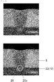
- Fig. 8 is a photograph of a sectional view of essential portions of the compressor 100 of the present invention.
- Fig. 8 shows the laser welding portion 20 formed through fiber laser.
- the laser welding portion 20 is formed astride the housing 5 and the stator 10 such that a light gathering point 20a of the fiber laser is located at the stator 10 instead of a boundary position between the housing 5 and the stator 10.
- a concave portion is formed in an outer wall of the housing 5 irradiated with fiber laser.
- the light gathering point 20a of fiber laser is located at the boundary position between the housing 5 and the stator 10, when a clearance is generated between the housing 5 and the stator 10, there is a possibility that welding of the fiber laser becomes insufficient because the spot size is small.
- the light gathering point 20a of fiber laser is located at the stator 10, even if a clearance is generated between the housing 5 and the stator 10, the stator 10 is melted and the clearance is filled and the stator 10 is welded to the housing 5.
- stator 10 is transition-fitted into the housing 5 before the laser welding portions 20 are formed.
- the stator 10 is transition-fitted into the housing 5 before the laser welding portions 20 are formed.
- the compressor of the present invention it is possible to enhance the efficiency of the compressor by preventing deformation and distortion of the electric motor. According to this, the present disclosure can be applied not only to the air conditioner compressor but also to a heat pump water heater.
Landscapes
- Engineering & Computer Science (AREA)
- Mechanical Engineering (AREA)
- General Engineering & Computer Science (AREA)
- Power Engineering (AREA)
- Physics & Mathematics (AREA)
- Optics & Photonics (AREA)
- Manufacturing & Machinery (AREA)
- Plasma & Fusion (AREA)
- Compressor (AREA)
- Iron Core Of Rotating Electric Machines (AREA)
- Applications Or Details Of Rotary Compressors (AREA)
Claims (13)
- Compresseur comprenant : un moteur électrique (2) incluant un stator (10) et un rotor (11) placé sur un côté interne du stator (10) ; un mécanisme de compression (3) ; et un carter (5),le stator (10) étant fixé à une paroi interne du carter (5) par l'intermédiaire d'une pluralité de parties de soudage au laser (20),la pluralité de parties de soudage au laser étant formées à des distances prédéterminées les unes des autres dans une direction circonférentielle du carter (5),les parties de soudage au laser (20) étant formées sur des longueurs prédéterminées,le stator (10) comprenant un noyau de stator (22) et un fil d'enroulement (25),le noyau de stator (22) étant formé par stratification d'une pluralité de tôles en acier électromagnétiques métalliques les unes sur les autres,le noyau de stator (22) incluant une partie culasse annulaire (22A), des dents (22B) faisant saillie vers l'intérieur dans une direction radiale de la partie culasse à partir de la partie culasse (22A) et des fentes (23) formées entre les dents adjacentes (22B),une pluralité d'interstices (24A) qui deviennent des passages à fluide frigorigène étant formés dans une surface périphérique externe de la partie culasse (22A) etles parties de soudage au laser (20) étant formées entre les interstices adjacents (24A),caractérisé en ce queles parties de soudage au laser (20) sont en outre formées en des emplacements sur un côté externe dans une direction radiale des fentes (23) etdes trous de passage à fluide frigorigène (24B) qui deviennent des passages à fluide frigorigène supplémentaires sont formés entre les interstices adjacents (24A) et dans la partie culasse (22A) située sur un côté externe dans une direction radiale des dents (22B).
- Compresseur selon la revendication 1, dans lequelles parties de soudage au laser (20) sont formées par un laser à fibre etun point de collecte de lumière (20a) du laser à fibre est situé sur le stator (10).
- Compresseur selon la revendication 1 ou 2, dans lequel
une partie concave est formée dans une paroi extérieure du carter (5) par la formation des parties de soudage au laser (20). - Compresseur selon l'une quelconque des revendications 1 à 3, dans lequelune longueur de la partie de soudage au laser (20) est supérieure ou égale à 10% et inférieure ou égale à 90% d'une longueur axiale du noyau de stator (22) etla partie de soudage au laser (20) est formée en une position au-delà de 5% de longueur de la longueur axiale du noyau de stator (22) dans la direction axiale du noyau de stator (22) à partir d'une surface d'extrémité du noyau de stator (22).
- Compresseur selon la revendication 4, dans lequel
la longueur de la partie de soudage au laser (20) est supérieure ou égale à 10% et inférieure ou égale à 20% de la longueur axiale du noyau de stator (22). - Compresseur selon l'une quelconque des revendications 1 à 5, dans lequel
la pluralité de parties de soudage au laser (20) sont formées à des hauteurs identiques dans une direction axiale du carter (5). - Compresseur selon l'une quelconque des revendications 1 à 5, dans lequel
la pluralité de parties de soudage au laser (20) sont formées à des hauteurs différentes dans une direction axiale du carter (5). - Compresseur selon l'une quelconque des revendications 1 à 7, dans lequel
les parties de soudage au laser (20) sont formées parallèlement à une direction axiale du carter (5). - Compresseur selon l'une quelconque des revendications 1 à 8, dans lequel
les parties de soudage au laser (20) s'inclinent par rapport à une direction axiale du carter (5). - Compresseur selon la revendication 9, dans lequel
une première partie de soudage au laser (20) et une deuxième partie de soudage au laser (20) placée à côté de la première partie de soudage au laser (20) dans la direction circonférentielle s'inclinent par rapport à la direction axiale du carter (5) dans des directions opposées l'une par rapport à l'autre. - Compresseur selon la revendication 10, dans lequel
une quatrième partie de soudage au laser (20) est formée en une position à un intervalle de 180° à partir d'une troisième partie de soudage au laser arbitraire (20) de la pluralité de parties de soudage au laser (20) dans la direction circonférentielle. - Compresseur selon la revendication 1, dans lequel
une largeur de la partie de soudage au laser (20) représente deux fois, ou plus, d'une épaisseur de l'une des tôles en acier électromagnétiques. - Compresseur selon l'une quelconque des revendications 1 à 12, dans lequel
les parties de soudage au laser (20) sont formées après un ajustement transitoire du stator (10) dans le carter (5).
Applications Claiming Priority (6)
| Application Number | Priority Date | Filing Date | Title |
|---|---|---|---|
| JP2013183829 | 2013-09-05 | ||
| JP2013193823 | 2013-09-19 | ||
| JP2013196428 | 2013-09-24 | ||
| JP2013212471 | 2013-10-10 | ||
| JP2013226269 | 2013-10-31 | ||
| PCT/JP2014/001376 WO2015033488A1 (fr) | 2013-09-05 | 2014-03-11 | Compresseur |
Publications (4)
| Publication Number | Publication Date |
|---|---|
| EP3043069A1 EP3043069A1 (fr) | 2016-07-13 |
| EP3043069A4 EP3043069A4 (fr) | 2016-08-31 |
| EP3043069B1 true EP3043069B1 (fr) | 2021-01-13 |
| EP3043069B8 EP3043069B8 (fr) | 2021-03-17 |
Family
ID=52627992
Family Applications (1)
| Application Number | Title | Priority Date | Filing Date |
|---|---|---|---|
| EP14841598.7A Active EP3043069B8 (fr) | 2013-09-05 | 2014-03-11 | Compresseur |
Country Status (4)
| Country | Link |
|---|---|
| EP (1) | EP3043069B8 (fr) |
| JP (1) | JP6222583B2 (fr) |
| CN (1) | CN105556122B (fr) |
| WO (1) | WO2015033488A1 (fr) |
Families Citing this family (12)
| Publication number | Priority date | Publication date | Assignee | Title |
|---|---|---|---|---|
| JP2015075047A (ja) * | 2013-10-10 | 2015-04-20 | パナソニックIpマネジメント株式会社 | 圧縮機 |
| WO2016185560A1 (fr) * | 2015-05-19 | 2016-11-24 | 三菱電機株式会社 | Machine électrique tournante |
| JP6686615B2 (ja) | 2016-03-28 | 2020-04-22 | 株式会社富士通ゼネラル | ロータリ圧縮機 |
| JP6377104B2 (ja) * | 2016-07-15 | 2018-08-22 | 三菱重工業株式会社 | モータおよびモータ搭載機器 |
| CN106670667B (zh) * | 2017-01-23 | 2022-10-18 | 广东顺德三合工业自动化设备股份有限公司 | 一种用于焊接压缩机与储液器的自动化生产线 |
| CN109458334A (zh) * | 2017-09-06 | 2019-03-12 | 上海海立电器有限公司 | 压缩机及其制造方法 |
| CN110076513B (zh) * | 2019-04-22 | 2021-10-08 | 广东美的智能机器人有限公司 | 焊接设备、具有其的生产线及焊接方法 |
| CN112855539A (zh) * | 2021-01-08 | 2021-05-28 | 广东美芝精密制造有限公司 | 压缩机及其组装方法 |
| CN115514176A (zh) * | 2021-06-22 | 2022-12-23 | 广东美芝精密制造有限公司 | 电机组装工艺和压缩机 |
| CN113798762B (zh) * | 2021-10-19 | 2023-12-29 | 湖北锐仕拓机电设备有限公司 | 一种壳体结构件的焊接工装及焊接方法 |
| DE212022000383U1 (de) * | 2022-03-29 | 2024-11-26 | Siam Compressor Industry Co., Ltd. | Verdichter |
| CN117564621A (zh) * | 2023-11-30 | 2024-02-20 | 贵州中航华强科技有限公司 | 一种基于数控加工的电机机壳加工方法 |
Family Cites Families (14)
| Publication number | Priority date | Publication date | Assignee | Title |
|---|---|---|---|---|
| JPS59126564U (ja) * | 1983-02-15 | 1984-08-25 | 三菱電機株式会社 | キヤンド式電動機 |
| JPS63189685A (ja) | 1987-01-30 | 1988-08-05 | Sanyo Electric Co Ltd | 密閉型回転圧縮機 |
| JPH05227685A (ja) * | 1991-11-26 | 1993-09-03 | Toshiba Corp | 回転電機 |
| JP4487382B2 (ja) * | 2000-04-27 | 2010-06-23 | 三菱電機株式会社 | 密閉型圧縮機およびその製造方法、冷凍・空調装置。 |
| KR100565264B1 (ko) * | 2005-01-13 | 2006-03-30 | 엘지전자 주식회사 | 왕복동식 압축기의 외측고정자 고정장치 |
| JP2007268609A (ja) * | 2006-03-07 | 2007-10-18 | Daikin Ind Ltd | 圧縮機の製造方法 |
| JP4241849B2 (ja) * | 2007-04-02 | 2009-03-18 | ダイキン工業株式会社 | 圧縮機 |
| JP2010011645A (ja) * | 2008-06-27 | 2010-01-14 | Daikin Ind Ltd | 積層鉄心、モータ及び圧縮機 |
| JP5131765B2 (ja) * | 2008-07-15 | 2013-01-30 | 日新製鋼株式会社 | 自動車用排気管の製造方法 |
| JP2010041851A (ja) * | 2008-08-06 | 2010-02-18 | Daikin Ind Ltd | 固定子とケーシングとの固定構造及びそれを備えた圧縮機 |
| JP5560007B2 (ja) * | 2009-08-26 | 2014-07-23 | アイチエレック株式会社 | 電動機および圧縮機 |
| JP2011055576A (ja) * | 2009-08-31 | 2011-03-17 | Daikin Industries Ltd | 圧縮機 |
| KR20110114367A (ko) * | 2010-04-13 | 2011-10-19 | 엘지전자 주식회사 | 밀폐형 압축기 |
| JP2013162676A (ja) * | 2012-02-07 | 2013-08-19 | Daikin Ind Ltd | 電動機および圧縮機 |
-
2014
- 2014-03-11 WO PCT/JP2014/001376 patent/WO2015033488A1/fr not_active Ceased
- 2014-03-11 CN CN201480048193.6A patent/CN105556122B/zh active Active
- 2014-03-11 EP EP14841598.7A patent/EP3043069B8/fr active Active
- 2014-03-11 JP JP2015535284A patent/JP6222583B2/ja active Active
Non-Patent Citations (1)
| Title |
|---|
| None * |
Also Published As
| Publication number | Publication date |
|---|---|
| EP3043069B8 (fr) | 2021-03-17 |
| JPWO2015033488A1 (ja) | 2017-03-02 |
| EP3043069A1 (fr) | 2016-07-13 |
| EP3043069A4 (fr) | 2016-08-31 |
| WO2015033488A1 (fr) | 2015-03-12 |
| CN105556122B (zh) | 2018-04-06 |
| CN105556122A (zh) | 2016-05-04 |
| JP6222583B2 (ja) | 2017-11-01 |
Similar Documents
| Publication | Publication Date | Title |
|---|---|---|
| EP3043069B1 (fr) | Compresseur | |
| JP6233726B2 (ja) | 圧縮機 | |
| EP2113987B1 (fr) | Isolant pour moteur, stator, moteur et compresseur | |
| JP4823787B2 (ja) | 回転子及び密閉型圧縮機及び冷凍サイクル装置 | |
| JP2011055576A (ja) | 圧縮機 | |
| CN101728914A (zh) | 永磁铁式旋转电机以及使用该电机的压缩机 | |
| CN105594099A (zh) | 永磁铁埋入型电动机、压缩机以及制冷空调装置 | |
| US12313050B2 (en) | Compressor | |
| JP6037362B2 (ja) | 永久磁石埋込型電動機、圧縮機及び冷凍空調装置 | |
| JP6328342B2 (ja) | ロータ、電動機、圧縮機および冷凍空調機 | |
| CN110024268B (zh) | 压缩机 | |
| CN108626120B (zh) | 电动压缩机 | |
| JP2014050290A (ja) | 固定子、モータ、及び圧縮機 | |
| JP2015075047A (ja) | 圧縮機 | |
| EP4407837B1 (fr) | Machine électrique tournante, compresseur et dispositif de réfrigération | |
| KR101166306B1 (ko) | 응력완화부를 갖는 고정자 및 그를 포함하는 압축기 | |
| JPWO2020208777A1 (ja) | 圧縮機、及び、圧縮機用電動機 | |
| JP7312967B2 (ja) | ステータ、モータおよび圧縮機 | |
| JP2008248889A (ja) | 密閉型圧縮機 | |
| JP5258406B2 (ja) | 永久磁石電動機 | |
| CN110291294B (zh) | 压缩机 | |
| WO2022101975A1 (fr) | Noyau de stator, stator, compresseur et procédé de production de compresseur | |
| KR102254667B1 (ko) | 로터리 압축기 및 그 제조방법 | |
| JP5575000B2 (ja) | 密閉型圧縮機 | |
| WO2024176546A1 (fr) | Moteur électrique, compresseur et dispositif |
Legal Events
| Date | Code | Title | Description |
|---|---|---|---|
| PUAI | Public reference made under article 153(3) epc to a published international application that has entered the european phase |
Free format text: ORIGINAL CODE: 0009012 |
|
| 17P | Request for examination filed |
Effective date: 20160405 |
|
| AK | Designated contracting states |
Kind code of ref document: A1 Designated state(s): AL AT BE BG CH CY CZ DE DK EE ES FI FR GB GR HR HU IE IS IT LI LT LU LV MC MK MT NL NO PL PT RO RS SE SI SK SM TR |
|
| AX | Request for extension of the european patent |
Extension state: BA ME |
|
| RIC1 | Information provided on ipc code assigned before grant |
Ipc: F04C 18/356 20060101ALI20160720BHEP Ipc: F04C 29/00 20060101ALI20160720BHEP Ipc: F04B 39/12 20060101ALI20160720BHEP Ipc: B23K 26/21 20140101ALI20160720BHEP Ipc: F04B 39/00 20060101AFI20160720BHEP Ipc: H02K 1/12 20060101ALI20160720BHEP Ipc: F04C 23/00 20060101ALI20160720BHEP |
|
| A4 | Supplementary search report drawn up and despatched |
Effective date: 20160728 |
|
| DAX | Request for extension of the european patent (deleted) | ||
| STAA | Information on the status of an ep patent application or granted ep patent |
Free format text: STATUS: EXAMINATION IS IN PROGRESS |
|
| 17Q | First examination report despatched |
Effective date: 20191122 |
|
| GRAP | Despatch of communication of intention to grant a patent |
Free format text: ORIGINAL CODE: EPIDOSNIGR1 |
|
| STAA | Information on the status of an ep patent application or granted ep patent |
Free format text: STATUS: GRANT OF PATENT IS INTENDED |
|
| INTG | Intention to grant announced |
Effective date: 20200729 |
|
| GRAS | Grant fee paid |
Free format text: ORIGINAL CODE: EPIDOSNIGR3 |
|
| GRAA | (expected) grant |
Free format text: ORIGINAL CODE: 0009210 |
|
| STAA | Information on the status of an ep patent application or granted ep patent |
Free format text: STATUS: THE PATENT HAS BEEN GRANTED |
|
| GRAT | Correction requested after decision to grant or after decision to maintain patent in amended form |
Free format text: ORIGINAL CODE: EPIDOSNCDEC |
|
| AK | Designated contracting states |
Kind code of ref document: B1 Designated state(s): AL AT BE BG CH CY CZ DE DK EE ES FI FR GB GR HR HU IE IS IT LI LT LU LV MC MK MT NL NO PL PT RO RS SE SI SK SM TR |
|
| REG | Reference to a national code |
Ref country code: GB Ref legal event code: FG4D |
|
| RIN1 | Information on inventor provided before grant (corrected) |
Inventor name: FUKUDA, AKINORI Inventor name: HASE, SHOZO Inventor name: FUNAKOSHI, DAISUKE Inventor name: SHIMIZU, ITSUO Inventor name: TAKAO, HITOSHI Inventor name: YOSHIZUKA, SHINICHI Inventor name: HIRATSUKA, TAKESHI Inventor name: SUGIE, TOSHIHIRO Inventor name: KARINO, TSUYOSHI Inventor name: KAWAHATA, NOBUYUKI |
|
| REG | Reference to a national code |
Ref country code: CH Ref legal event code: EP |
|
| REG | Reference to a national code |
Ref country code: DE Ref legal event code: R096 Ref document number: 602014074282 Country of ref document: DE |
|
| REG | Reference to a national code |
Ref country code: CH Ref legal event code: PK Free format text: BERICHTIGUNGEN |
|
| REG | Reference to a national code |
Ref country code: IE Ref legal event code: FG4D |
|
| REG | Reference to a national code |
Ref country code: AT Ref legal event code: REF Ref document number: 1354769 Country of ref document: AT Kind code of ref document: T Effective date: 20210215 |
|
| REG | Reference to a national code |
Ref country code: DE Ref legal event code: R083 Ref document number: 602014074282 Country of ref document: DE |
|
| RIN2 | Information on inventor provided after grant (corrected) |
Inventor name: KAWAHATA, NOBUYUKI Inventor name: HIRATSUKA, TAKESHI Inventor name: YOSHIZUKA, SHINICHI Inventor name: KARINO, TSUYOSHI Inventor name: TAKAO, HITOSHI Inventor name: SHIMIZU, ITSUO Inventor name: HASE, SHOZO Inventor name: FUKUDA, AKINORI Inventor name: SUGIE, TOSHIHIRO Inventor name: FUNAKOSHI, DAISUKE |
|
| REG | Reference to a national code |
Ref country code: CH Ref legal event code: PK Free format text: BERICHTIGUNG B8 |
|
| REG | Reference to a national code |
Ref country code: AT Ref legal event code: MK05 Ref document number: 1354769 Country of ref document: AT Kind code of ref document: T Effective date: 20210113 |
|
| REG | Reference to a national code |
Ref country code: NL Ref legal event code: MP Effective date: 20210113 |
|
| REG | Reference to a national code |
Ref country code: LT Ref legal event code: MG9D |
|
| PG25 | Lapsed in a contracting state [announced via postgrant information from national office to epo] |
Ref country code: LT Free format text: LAPSE BECAUSE OF FAILURE TO SUBMIT A TRANSLATION OF THE DESCRIPTION OR TO PAY THE FEE WITHIN THE PRESCRIBED TIME-LIMIT Effective date: 20210113 Ref country code: PT Free format text: LAPSE BECAUSE OF FAILURE TO SUBMIT A TRANSLATION OF THE DESCRIPTION OR TO PAY THE FEE WITHIN THE PRESCRIBED TIME-LIMIT Effective date: 20210513 Ref country code: FI Free format text: LAPSE BECAUSE OF FAILURE TO SUBMIT A TRANSLATION OF THE DESCRIPTION OR TO PAY THE FEE WITHIN THE PRESCRIBED TIME-LIMIT Effective date: 20210113 Ref country code: HR Free format text: LAPSE BECAUSE OF FAILURE TO SUBMIT A TRANSLATION OF THE DESCRIPTION OR TO PAY THE FEE WITHIN THE PRESCRIBED TIME-LIMIT Effective date: 20210113 Ref country code: GR Free format text: LAPSE BECAUSE OF FAILURE TO SUBMIT A TRANSLATION OF THE DESCRIPTION OR TO PAY THE FEE WITHIN THE PRESCRIBED TIME-LIMIT Effective date: 20210414 Ref country code: BG Free format text: LAPSE BECAUSE OF FAILURE TO SUBMIT A TRANSLATION OF THE DESCRIPTION OR TO PAY THE FEE WITHIN THE PRESCRIBED TIME-LIMIT Effective date: 20210413 Ref country code: NL Free format text: LAPSE BECAUSE OF FAILURE TO SUBMIT A TRANSLATION OF THE DESCRIPTION OR TO PAY THE FEE WITHIN THE PRESCRIBED TIME-LIMIT Effective date: 20210113 Ref country code: NO Free format text: LAPSE BECAUSE OF FAILURE TO SUBMIT A TRANSLATION OF THE DESCRIPTION OR TO PAY THE FEE WITHIN THE PRESCRIBED TIME-LIMIT Effective date: 20210413 |
|
| PG25 | Lapsed in a contracting state [announced via postgrant information from national office to epo] |
Ref country code: SE Free format text: LAPSE BECAUSE OF FAILURE TO SUBMIT A TRANSLATION OF THE DESCRIPTION OR TO PAY THE FEE WITHIN THE PRESCRIBED TIME-LIMIT Effective date: 20210113 Ref country code: LV Free format text: LAPSE BECAUSE OF FAILURE TO SUBMIT A TRANSLATION OF THE DESCRIPTION OR TO PAY THE FEE WITHIN THE PRESCRIBED TIME-LIMIT Effective date: 20210113 Ref country code: RS Free format text: LAPSE BECAUSE OF FAILURE TO SUBMIT A TRANSLATION OF THE DESCRIPTION OR TO PAY THE FEE WITHIN THE PRESCRIBED TIME-LIMIT Effective date: 20210113 Ref country code: PL Free format text: LAPSE BECAUSE OF FAILURE TO SUBMIT A TRANSLATION OF THE DESCRIPTION OR TO PAY THE FEE WITHIN THE PRESCRIBED TIME-LIMIT Effective date: 20210113 Ref country code: AT Free format text: LAPSE BECAUSE OF FAILURE TO SUBMIT A TRANSLATION OF THE DESCRIPTION OR TO PAY THE FEE WITHIN THE PRESCRIBED TIME-LIMIT Effective date: 20210113 |
|
| PG25 | Lapsed in a contracting state [announced via postgrant information from national office to epo] |
Ref country code: IS Free format text: LAPSE BECAUSE OF FAILURE TO SUBMIT A TRANSLATION OF THE DESCRIPTION OR TO PAY THE FEE WITHIN THE PRESCRIBED TIME-LIMIT Effective date: 20210513 |
|
| REG | Reference to a national code |
Ref country code: DE Ref legal event code: R097 Ref document number: 602014074282 Country of ref document: DE |
|
| PG25 | Lapsed in a contracting state [announced via postgrant information from national office to epo] |
Ref country code: SM Free format text: LAPSE BECAUSE OF FAILURE TO SUBMIT A TRANSLATION OF THE DESCRIPTION OR TO PAY THE FEE WITHIN THE PRESCRIBED TIME-LIMIT Effective date: 20210113 Ref country code: MC Free format text: LAPSE BECAUSE OF FAILURE TO SUBMIT A TRANSLATION OF THE DESCRIPTION OR TO PAY THE FEE WITHIN THE PRESCRIBED TIME-LIMIT Effective date: 20210113 Ref country code: EE Free format text: LAPSE BECAUSE OF FAILURE TO SUBMIT A TRANSLATION OF THE DESCRIPTION OR TO PAY THE FEE WITHIN THE PRESCRIBED TIME-LIMIT Effective date: 20210113 Ref country code: CZ Free format text: LAPSE BECAUSE OF FAILURE TO SUBMIT A TRANSLATION OF THE DESCRIPTION OR TO PAY THE FEE WITHIN THE PRESCRIBED TIME-LIMIT Effective date: 20210113 |
|
| REG | Reference to a national code |
Ref country code: CH Ref legal event code: PL |
|
| PLBE | No opposition filed within time limit |
Free format text: ORIGINAL CODE: 0009261 |
|
| STAA | Information on the status of an ep patent application or granted ep patent |
Free format text: STATUS: NO OPPOSITION FILED WITHIN TIME LIMIT |
|
| PG25 | Lapsed in a contracting state [announced via postgrant information from national office to epo] |
Ref country code: ES Free format text: LAPSE BECAUSE OF FAILURE TO SUBMIT A TRANSLATION OF THE DESCRIPTION OR TO PAY THE FEE WITHIN THE PRESCRIBED TIME-LIMIT Effective date: 20210113 Ref country code: DK Free format text: LAPSE BECAUSE OF FAILURE TO SUBMIT A TRANSLATION OF THE DESCRIPTION OR TO PAY THE FEE WITHIN THE PRESCRIBED TIME-LIMIT Effective date: 20210113 Ref country code: SK Free format text: LAPSE BECAUSE OF FAILURE TO SUBMIT A TRANSLATION OF THE DESCRIPTION OR TO PAY THE FEE WITHIN THE PRESCRIBED TIME-LIMIT Effective date: 20210113 Ref country code: RO Free format text: LAPSE BECAUSE OF FAILURE TO SUBMIT A TRANSLATION OF THE DESCRIPTION OR TO PAY THE FEE WITHIN THE PRESCRIBED TIME-LIMIT Effective date: 20210113 |
|
| REG | Reference to a national code |
Ref country code: BE Ref legal event code: MM Effective date: 20210331 |
|
| 26N | No opposition filed |
Effective date: 20211014 |
|
| GBPC | Gb: european patent ceased through non-payment of renewal fee |
Effective date: 20210413 |
|
| PG25 | Lapsed in a contracting state [announced via postgrant information from national office to epo] |
Ref country code: FR Free format text: LAPSE BECAUSE OF NON-PAYMENT OF DUE FEES Effective date: 20210313 Ref country code: IE Free format text: LAPSE BECAUSE OF NON-PAYMENT OF DUE FEES Effective date: 20210311 Ref country code: GB Free format text: LAPSE BECAUSE OF NON-PAYMENT OF DUE FEES Effective date: 20210413 Ref country code: LU Free format text: LAPSE BECAUSE OF NON-PAYMENT OF DUE FEES Effective date: 20210311 Ref country code: LI Free format text: LAPSE BECAUSE OF NON-PAYMENT OF DUE FEES Effective date: 20210331 Ref country code: CH Free format text: LAPSE BECAUSE OF NON-PAYMENT OF DUE FEES Effective date: 20210331 Ref country code: AL Free format text: LAPSE BECAUSE OF FAILURE TO SUBMIT A TRANSLATION OF THE DESCRIPTION OR TO PAY THE FEE WITHIN THE PRESCRIBED TIME-LIMIT Effective date: 20210113 |
|
| PG25 | Lapsed in a contracting state [announced via postgrant information from national office to epo] |
Ref country code: SI Free format text: LAPSE BECAUSE OF FAILURE TO SUBMIT A TRANSLATION OF THE DESCRIPTION OR TO PAY THE FEE WITHIN THE PRESCRIBED TIME-LIMIT Effective date: 20210113 |
|
| PG25 | Lapsed in a contracting state [announced via postgrant information from national office to epo] |
Ref country code: IT Free format text: LAPSE BECAUSE OF FAILURE TO SUBMIT A TRANSLATION OF THE DESCRIPTION OR TO PAY THE FEE WITHIN THE PRESCRIBED TIME-LIMIT Effective date: 20210113 |
|
| PG25 | Lapsed in a contracting state [announced via postgrant information from national office to epo] |
Ref country code: IS Free format text: LAPSE BECAUSE OF FAILURE TO SUBMIT A TRANSLATION OF THE DESCRIPTION OR TO PAY THE FEE WITHIN THE PRESCRIBED TIME-LIMIT Effective date: 20210513 |
|
| PG25 | Lapsed in a contracting state [announced via postgrant information from national office to epo] |
Ref country code: BE Free format text: LAPSE BECAUSE OF NON-PAYMENT OF DUE FEES Effective date: 20210331 |
|
| PG25 | Lapsed in a contracting state [announced via postgrant information from national office to epo] |
Ref country code: HU Free format text: LAPSE BECAUSE OF FAILURE TO SUBMIT A TRANSLATION OF THE DESCRIPTION OR TO PAY THE FEE WITHIN THE PRESCRIBED TIME-LIMIT; INVALID AB INITIO Effective date: 20140311 |
|
| PG25 | Lapsed in a contracting state [announced via postgrant information from national office to epo] |
Ref country code: CY Free format text: LAPSE BECAUSE OF FAILURE TO SUBMIT A TRANSLATION OF THE DESCRIPTION OR TO PAY THE FEE WITHIN THE PRESCRIBED TIME-LIMIT Effective date: 20210113 |
|
| PG25 | Lapsed in a contracting state [announced via postgrant information from national office to epo] |
Ref country code: MK Free format text: LAPSE BECAUSE OF FAILURE TO SUBMIT A TRANSLATION OF THE DESCRIPTION OR TO PAY THE FEE WITHIN THE PRESCRIBED TIME-LIMIT Effective date: 20210113 |
|
| PG25 | Lapsed in a contracting state [announced via postgrant information from national office to epo] |
Ref country code: MT Free format text: LAPSE BECAUSE OF FAILURE TO SUBMIT A TRANSLATION OF THE DESCRIPTION OR TO PAY THE FEE WITHIN THE PRESCRIBED TIME-LIMIT Effective date: 20210113 |
|
| PG25 | Lapsed in a contracting state [announced via postgrant information from national office to epo] |
Ref country code: TR Free format text: LAPSE BECAUSE OF FAILURE TO SUBMIT A TRANSLATION OF THE DESCRIPTION OR TO PAY THE FEE WITHIN THE PRESCRIBED TIME-LIMIT Effective date: 20210113 |
|
| PGFP | Annual fee paid to national office [announced via postgrant information from national office to epo] |
Ref country code: DE Payment date: 20260319 Year of fee payment: 13 |