WO2015033488A1 - Compresseur - Google Patents
Compresseur Download PDFInfo
- Publication number
- WO2015033488A1 WO2015033488A1 PCT/JP2014/001376 JP2014001376W WO2015033488A1 WO 2015033488 A1 WO2015033488 A1 WO 2015033488A1 JP 2014001376 W JP2014001376 W JP 2014001376W WO 2015033488 A1 WO2015033488 A1 WO 2015033488A1
- Authority
- WO
- WIPO (PCT)
- Prior art keywords
- laser
- housing
- stator
- compressor according
- laser welding
- Prior art date
- Legal status (The legal status is an assumption and is not a legal conclusion. Google has not performed a legal analysis and makes no representation as to the accuracy of the status listed.)
- Ceased
Links
Images




Classifications
-
- H—ELECTRICITY
- H02—GENERATION; CONVERSION OR DISTRIBUTION OF ELECTRIC POWER
- H02K—DYNAMO-ELECTRIC MACHINES
- H02K1/00—Details of the magnetic circuit
- H02K1/06—Details of the magnetic circuit characterised by the shape, form or construction
- H02K1/12—Stationary parts of the magnetic circuit
- H02K1/18—Means for mounting or fastening magnetic stationary parts on to, or to, the stator structures
- H02K1/185—Means for mounting or fastening magnetic stationary parts on to, or to, the stator structures to outer stators
-
- F—MECHANICAL ENGINEERING; LIGHTING; HEATING; WEAPONS; BLASTING
- F04—POSITIVE - DISPLACEMENT MACHINES FOR LIQUIDS; PUMPS FOR LIQUIDS OR ELASTIC FLUIDS
- F04B—POSITIVE-DISPLACEMENT MACHINES FOR LIQUIDS; PUMPS
- F04B39/00—Component parts, details, or accessories, of pumps or pumping systems specially adapted for elastic fluids, not otherwise provided for in, or of interest apart from, groups F04B25/00 - F04B37/00
-
- B—PERFORMING OPERATIONS; TRANSPORTING
- B23—MACHINE TOOLS; METAL-WORKING NOT OTHERWISE PROVIDED FOR
- B23K—SOLDERING OR UNSOLDERING; WELDING; CLADDING OR PLATING BY SOLDERING OR WELDING; CUTTING BY APPLYING HEAT LOCALLY, e.g. FLAME CUTTING; WORKING BY LASER BEAM
- B23K26/00—Working by laser beam, e.g. welding, cutting or boring
- B23K26/20—Bonding
- B23K26/21—Bonding by welding
- B23K26/22—Spot welding
-
- F—MECHANICAL ENGINEERING; LIGHTING; HEATING; WEAPONS; BLASTING
- F04—POSITIVE - DISPLACEMENT MACHINES FOR LIQUIDS; PUMPS FOR LIQUIDS OR ELASTIC FLUIDS
- F04B—POSITIVE-DISPLACEMENT MACHINES FOR LIQUIDS; PUMPS
- F04B39/00—Component parts, details, or accessories, of pumps or pumping systems specially adapted for elastic fluids, not otherwise provided for in, or of interest apart from, groups F04B25/00 - F04B37/00
- F04B39/0027—Pulsation and noise damping means
-
- F—MECHANICAL ENGINEERING; LIGHTING; HEATING; WEAPONS; BLASTING
- F04—POSITIVE - DISPLACEMENT MACHINES FOR LIQUIDS; PUMPS FOR LIQUIDS OR ELASTIC FLUIDS
- F04B—POSITIVE-DISPLACEMENT MACHINES FOR LIQUIDS; PUMPS
- F04B39/00—Component parts, details, or accessories, of pumps or pumping systems specially adapted for elastic fluids, not otherwise provided for in, or of interest apart from, groups F04B25/00 - F04B37/00
- F04B39/12—Casings; Cylinders; Cylinder heads; Fluid connections
-
- F—MECHANICAL ENGINEERING; LIGHTING; HEATING; WEAPONS; BLASTING
- F04—POSITIVE - DISPLACEMENT MACHINES FOR LIQUIDS; PUMPS FOR LIQUIDS OR ELASTIC FLUIDS
- F04C—ROTARY-PISTON, OR OSCILLATING-PISTON, POSITIVE-DISPLACEMENT MACHINES FOR LIQUIDS; ROTARY-PISTON, OR OSCILLATING-PISTON, POSITIVE-DISPLACEMENT PUMPS
- F04C23/00—Combinations of two or more pumps, each being of rotary-piston or oscillating-piston type, specially adapted for elastic fluids; Pumping installations specially adapted for elastic fluids; Multi-stage pumps specially adapted for elastic fluids
- F04C23/008—Hermetic pumps
-
- F—MECHANICAL ENGINEERING; LIGHTING; HEATING; WEAPONS; BLASTING
- F04—POSITIVE - DISPLACEMENT MACHINES FOR LIQUIDS; PUMPS FOR LIQUIDS OR ELASTIC FLUIDS
- F04C—ROTARY-PISTON, OR OSCILLATING-PISTON, POSITIVE-DISPLACEMENT MACHINES FOR LIQUIDS; ROTARY-PISTON, OR OSCILLATING-PISTON, POSITIVE-DISPLACEMENT PUMPS
- F04C29/00—Component parts, details or accessories of pumps or pumping installations, not provided for in groups F04C18/00 - F04C28/00
-
- F—MECHANICAL ENGINEERING; LIGHTING; HEATING; WEAPONS; BLASTING
- F04—POSITIVE - DISPLACEMENT MACHINES FOR LIQUIDS; PUMPS FOR LIQUIDS OR ELASTIC FLUIDS
- F04C—ROTARY-PISTON, OR OSCILLATING-PISTON, POSITIVE-DISPLACEMENT MACHINES FOR LIQUIDS; ROTARY-PISTON, OR OSCILLATING-PISTON, POSITIVE-DISPLACEMENT PUMPS
- F04C29/00—Component parts, details or accessories of pumps or pumping installations, not provided for in groups F04C18/00 - F04C28/00
- F04C29/0042—Driving elements, brakes, couplings, transmissions specially adapted for pumps
- F04C29/0085—Prime movers
-
- H—ELECTRICITY
- H02—GENERATION; CONVERSION OR DISTRIBUTION OF ELECTRIC POWER
- H02K—DYNAMO-ELECTRIC MACHINES
- H02K1/00—Details of the magnetic circuit
- H02K1/06—Details of the magnetic circuit characterised by the shape, form or construction
- H02K1/12—Stationary parts of the magnetic circuit
-
- H—ELECTRICITY
- H02—GENERATION; CONVERSION OR DISTRIBUTION OF ELECTRIC POWER
- H02K—DYNAMO-ELECTRIC MACHINES
- H02K15/00—Processes or apparatus specially adapted for manufacturing, assembling, maintaining or repairing of dynamo-electric machines
- H02K15/14—Casings; Enclosures; Supports
-
- F—MECHANICAL ENGINEERING; LIGHTING; HEATING; WEAPONS; BLASTING
- F04—POSITIVE - DISPLACEMENT MACHINES FOR LIQUIDS; PUMPS FOR LIQUIDS OR ELASTIC FLUIDS
- F04C—ROTARY-PISTON, OR OSCILLATING-PISTON, POSITIVE-DISPLACEMENT MACHINES FOR LIQUIDS; ROTARY-PISTON, OR OSCILLATING-PISTON, POSITIVE-DISPLACEMENT PUMPS
- F04C18/00—Rotary-piston pumps specially adapted for elastic fluids
- F04C18/30—Rotary-piston pumps specially adapted for elastic fluids having the characteristics covered by two or more of groups F04C18/02, F04C18/08, F04C18/22, F04C18/24, F04C18/48, or having the characteristics covered by one of these groups together with some other type of movement between co-operating members
- F04C18/34—Rotary-piston pumps specially adapted for elastic fluids having the characteristics covered by two or more of groups F04C18/02, F04C18/08, F04C18/22, F04C18/24, F04C18/48, or having the characteristics covered by one of these groups together with some other type of movement between co-operating members having the movement defined in group F04C18/08 or F04C18/22 and relative reciprocation between the co-operating members
- F04C18/356—Rotary-piston pumps specially adapted for elastic fluids having the characteristics covered by two or more of groups F04C18/02, F04C18/08, F04C18/22, F04C18/24, F04C18/48, or having the characteristics covered by one of these groups together with some other type of movement between co-operating members having the movement defined in group F04C18/08 or F04C18/22 and relative reciprocation between the co-operating members with vanes reciprocating with respect to the outer member
-
- F—MECHANICAL ENGINEERING; LIGHTING; HEATING; WEAPONS; BLASTING
- F04—POSITIVE - DISPLACEMENT MACHINES FOR LIQUIDS; PUMPS FOR LIQUIDS OR ELASTIC FLUIDS
- F04C—ROTARY-PISTON, OR OSCILLATING-PISTON, POSITIVE-DISPLACEMENT MACHINES FOR LIQUIDS; ROTARY-PISTON, OR OSCILLATING-PISTON, POSITIVE-DISPLACEMENT PUMPS
- F04C2230/00—Manufacture
- F04C2230/20—Manufacture essentially without removing material
- F04C2230/23—Manufacture essentially without removing material by permanently joining parts together
- F04C2230/231—Manufacture essentially without removing material by permanently joining parts together by welding
-
- F—MECHANICAL ENGINEERING; LIGHTING; HEATING; WEAPONS; BLASTING
- F04—POSITIVE - DISPLACEMENT MACHINES FOR LIQUIDS; PUMPS FOR LIQUIDS OR ELASTIC FLUIDS
- F04C—ROTARY-PISTON, OR OSCILLATING-PISTON, POSITIVE-DISPLACEMENT MACHINES FOR LIQUIDS; ROTARY-PISTON, OR OSCILLATING-PISTON, POSITIVE-DISPLACEMENT PUMPS
- F04C23/00—Combinations of two or more pumps, each being of rotary-piston or oscillating-piston type, specially adapted for elastic fluids; Pumping installations specially adapted for elastic fluids; Multi-stage pumps specially adapted for elastic fluids
- F04C23/001—Combinations of two or more pumps, each being of rotary-piston or oscillating-piston type, specially adapted for elastic fluids; Pumping installations specially adapted for elastic fluids; Multi-stage pumps specially adapted for elastic fluids of similar working principle
Definitions
- the present invention relates to a compressor used for an air conditioner, a refrigerator, a blower, a water heater, and the like.
- a compressor is used for the refrigeration system and the air conditioner.
- the compressor sucks in the working refrigerant evaporated in the evaporator, compresses the working refrigerant to a pressure necessary for condensation, and delivers the high-temperature high-pressure working refrigerant into the working refrigerant circuit.
- Such a compressor houses a compression mechanism portion for compressing a refrigerant gas and a motor portion for driving the compression mechanism portion in a sealed container.
- the motor unit includes a stator fixed to the inner wall surface of the hermetic container, and a rotor transmitting rotational power to the drive shaft.
- the stator of the motor unit has been closely fixed to the inner wall of the sealed container by shrink fitting.
- this method there is a problem that the stator is deformed due to the contraction stress of the closed container and the efficiency of the motor unit is reduced. That is, a compressive stress is applied to the stator, and the electromagnetic steel plates constituting the stator are distorted, and a magnetic field distortion occurs when the rotor rotates, causing a decrease in the efficiency of the motor unit.
- the vibration generated in the stator is transmitted to the closed container, vibration and noise of the compressor become a problem.
- Patent Document 1 the method of closely fixing a stator to a sealed container by laser welding is proposed (for example, refer patent document 1).
- Patent Document 1 laser irradiation is performed all over the axial direction of the stator core.
- the stator is fixed to the inner wall of the housing by the plurality of laser welds, and the plurality of laser welds are formed at predetermined intervals in the circumferential direction of the housing, and the respective laser welds Are formed over a predetermined length.
- a compressor according to the present invention includes a motor unit including a stator and a rotor disposed inside the stator, a compression mechanism unit, and a housing.
- the stator is fixed to the inner wall of the housing by a plurality of laser welds, and the plurality of laser welds are formed at predetermined intervals in the circumferential direction of the housing, and the respective laser welds are formed.
- the part is formed over a predetermined length.
- the efficiency fall of the motor part by deformation of a stator can be prevented. Further, according to the present invention, no swelling (convex portion) occurs in the laser welded portion, so that the damage of the covering material (heat insulating material, soundproofing material, heat storage material, etc.) covering the outer peripheral surface of the compressor can be prevented. it can.
- Sectional view of a compressor according to an embodiment of the present invention A plan view of a motor unit according to an embodiment of the present invention
- the figure explaining the laser welding part concerning the embodiment of the present invention The figure which shows the relationship of the motor part and housing which concern on embodiment of this invention.
- the figure explaining the laser welding part concerning the modification 1 of the present invention The figure explaining the laser welding part concerning modification 2 of the present invention Diagram for explaining the distance between laser welds according to the embodiment of the present invention and the second modification Main part cross-sectional photograph of the compressor according to the present invention
- the stator is fixed to the inner wall of the housing by a plurality of laser welds, and the plurality of laser welds are formed at predetermined intervals in the circumferential direction of the housing.
- Each of the laser welds is formed over a predetermined length.
- the laser welding is performed on the outer peripheral surface of the yoke portion by forming a plurality of air gaps that are refrigerant passages, between adjacent air gaps and at a position outside the radial direction of the slots. Form a part.
- a refrigerant passage hole serving as the refrigerant passage is formed in the yoke portion which is between the adjacent air gaps and which is the outer side in the radial direction of the teeth portion.
- the laser welding portion is formed by a fiber laser, and a focusing point of the fiber laser is used as the stator.
- a fiber laser By using a fiber laser, the heat effect at the time of welding is small, and the focusing point of the fiber laser can be reliably welded with a small spot size by using the stator instead of the boundary position between the housing and the stator. .
- a recess is formed on the outer wall of the housing by forming the laser welding portion.
- a sixth aspect of the invention sets the length of the laser welding portion to 10% or more and 90% or less of the axial length of the stator core, from the end face of the stator core in the axial direction of the stator core
- the laser welded portion is formed at a position beyond 5% of the axial length of the stator core.
- the length of the laser weld exceeds 90% of the axial length of the stator core, or 5% of the axial length of the stator core in the axial direction of the stator core from the end face of the stator core If the laser weld is formed at a position within the length range, sparks generated when welding the stator and the housing may protrude from the upper and lower ends of the stator core into the housing.
- the length of the laser welding portion is 10% or more and 20% or less of the axial length of the stator core.
- the laser welding portion is formed at the same height in the axial direction of the housing.
- the laser welds are formed at different heights in the axial direction of the housing.
- distortion and vibration of the stator can be obtained by holding the distortion of the magnetic field generated during high-speed rotation of the motor and the axial vibration generated by the moment force of the rotational torque with the laser welds of different heights. It can be suppressed.
- the laser welding portion is formed in parallel to the axial direction of the housing.
- the laser welding portion is formed to be inclined with respect to the axial direction of the housing.
- the welding range can be expanded in the circumferential direction of the housing, and the torque fluctuation received by the stator during compression and the torque fluctuation generated by the rotation of the motor unit can be evenly distributed and held by the plurality of welds.
- the first laser welding portion, and the second laser welding portion circumferentially adjacent to the first laser welding portion are inclined directions with respect to the axial direction of the housing. The opposite.
- the distance between adjacent laser welds can be partially shortened, and the circumferential rigidity of the housing can be increased.
- welding can be performed while rotating the housing, the time required for welding can be shortened.
- the fourth laser weld is formed at a position spaced 180 degrees in the circumferential direction from any third laser weld of the plurality of laser welds. Thereby, it becomes possible to offset the distortion in the circumferential direction due to the laser welding.
- the width of the laser welded portion is twice or more the thickness of the electromagnetic steel sheet.
- the fifteenth invention uses the HFC refrigerant R32 as the refrigerant compressed by the compression mechanism section.
- the refrigerant circulation amount is increased by about 10%, and the efficiency is not reduced even if the load torque is increased, and noise and vibration of the motor portion can be suppressed to the same level or less as in the conventional refrigerant use.
- the laser welded portion is formed after the stator is fitted in the housing. Since the gap between the housing and the stator can be eliminated by the intermediate fitting, welding at the laser welding portion can be performed reliably.
- FIG. 1 is a longitudinal sectional view of a compressor 100 according to an embodiment of the present invention.
- the compressor 100 includes a sealed container 1, a motor unit 2, a compression mechanism unit 3, and a drive shaft 4.
- the closed container 1 comprises a cylindrical housing 5 and an upper cover 6 and a lower cover 7 closing the opening of the housing 5.
- the compression mechanism portion 3 is disposed at the lower portion of the housing 5.
- the motor unit 2 is disposed on the compression mechanism unit 3 inside the housing 5.
- the compression mechanism unit 3 and the motor unit 2 are connected by the drive shaft 4.
- the upper cover 6 is provided with a terminal 8 for supplying electric power to the motor unit 2.
- An oil reservoir 9 for holding lubricating oil is formed at the bottom of the closed container 1.
- the motor unit 2 is composed of a stator 10 and a rotor 11.
- the stator 10 is fixed to the inner wall of the housing 5.
- the rotor 11 is fixed to the drive shaft 4 and rotates with the drive shaft 4. Both ends of the drive shaft 4 are rotatably supported by the upper bearing member 12 and the lower bearing member 13.
- the compression mechanism portion 3 includes an upper bearing member 12, a lower bearing member 13, cylinders 15a and 15b, rolling pistons 16a and 16b, and vanes (not shown).
- a discharge pipe 17 is provided in the upper part of the closed container 1.
- the discharge pipe 17 penetrates the upper portion of the upper cover 6 and is open toward the inner space of the closed container 1.
- the discharge pipe 17 plays a role as a discharge flow path for guiding the refrigerant gas compressed by the compression mechanism unit 3 to the outside of the closed container 1.
- the internal space of the closed vessel 1 is filled with the compressed refrigerant.
- the accumulator 18 is provided in order to prevent the liquid compression of the compressor 100.
- the accumulator 18 separates the refrigerant gas into gas and liquid before directly drawing the refrigerant gas into the compressor 100.
- the accumulator 18 includes a cylindrical case 19, a refrigerant gas introduction pipe connected to the upper portion of the case 19, and two refrigerant gas lead pipes connected to the lower portion of the case 19.
- the compressor 100 As a refrigerant compressed by the compression mechanism section 3, it is preferable to use an HFC refrigerant R32.
- the HFC refrigerant R32 By using the HFC refrigerant R32, the refrigerant circulation amount is increased by about 10% as compared to the conventional alternative refrigerant, and the noise and the vibration of the motor unit 2 can be suppressed without reducing the efficiency even if the load torque increases.
- the stator 10 and the housing 5 of the motor unit 2 are welded and fixed by laser irradiation with a fiber laser.
- FIG. 2 shows a plan view of the motor unit 2 according to the embodiment of the present invention.
- a DC IPM motor having distributed winding of a winding method is suitable.
- the motor unit 2 includes a stator 10 fixed to the inner wall surface of the housing 5 and a rotor 11 for transmitting rotational power to the shaft.
- the stator 10 has a stator core 22 and a winding 25.
- the stator core 22 is formed by laminating a plurality of electromagnetic steel plates made of a metal material.
- the stator core 22 includes an annular yoke portion 22A, a tooth portion 22B projecting radially inward from the yoke portion 22A, a slot 23 formed between adjacent tooth portions 22B, and an inner side of the tooth portion 22B. And a through hole 22C in which the rotor 11 is disposed. Insulating paper (not shown) is inserted in the slot 23 in order to maintain the insulation with the winding 25.
- a plurality of air gaps 24A serving as a refrigerant passage are provided on the outer peripheral portion of the stator 10, that is, the outer peripheral surface of the yoke portion 22A.
- the gap 24A makes the width gap a in the circumferential direction of the yoke portion 22A larger than the depth gap in the radial direction of the yoke portion 22A. It is preferable that the width gap a in the gap 24A be wider than the circumferential width b of one slot 23, and the width gap a be twice or more the circumferential width b of the slot 23.
- the air gap 24A is provided so as to penetrate the motor unit 2 in the axial direction, and allows the upper space and the lower space of the motor unit 2 to communicate with each other.
- a refrigerant passage hole 24B serving as a refrigerant passage is formed in the yoke portion 22A, which is between the adjacent air gaps 24A and is the outer side in the radial direction of the teeth portion 22B.
- the diameter c of the refrigerant passage hole 24B is smaller than the minimum width d of the teeth portion 22B. As described above, by making the diameter c of the refrigerant passage hole 24B smaller than the minimum width d of the teeth portion 22B, it is possible to secure the refrigerant passage and to prevent the efficiency reduction of the motor unit 2.
- the refrigerant passage hole 24B is provided to penetrate the motor unit 2 in the axial direction, and allows the upper space and the lower space of the motor unit 2 to communicate with each other.
- the refrigerant compressed by the compression mechanism 3 and discharged from the opening of the muffler cover 21 passes through the air gap 24A of the stator 10, the air gap (not shown) of the rotor 11 and the refrigerant passage hole 24B. It is led to space.
- the stator 10 and the housing 5 are fixed by six laser welds 20.
- the laser welding portion 20 is formed between the adjacent air gaps 24A and at a position which is on the outer side in the radial direction of the slot 23.
- the laser welding portion 20 is formed such that the focusing point of the fiber laser is at the position of the stator 10.
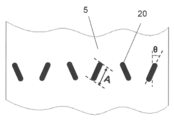
- FIG. 3 is a view (a developed view of the housing 5) for explaining the laser welding portion 20 according to the present embodiment.
- the laser welds 20 are formed at predetermined intervals in the circumferential direction of the housing 5. In the present embodiment, six laser welds 20 are provided. In addition, the mutual space
- the width of the laser welded portion 20 is preferably twice or more the thickness of the electromagnetic steel sheet.
- the width of the laser welded portion 20 By setting the width of the laser welded portion 20 to be twice or more the thickness of the electromagnetic steel sheet, the penetration depth into the stator 10 can be suppressed, and the efficiency reduction of the motor portion 2 can be prevented.
- the width of the laser weld 20 is, for example, 0.5 mm to 3 mm.
- the laser welding portion 20 in the present embodiment is formed over a predetermined length in the axial direction of the housing 5. That is, the laser welding portion 20 is linear.
- the laser welding portion 20 is formed at a point like the welding point in the conventional spot welding, the local distortion in the stator 10 is large because it is necessary to irradiate the laser at a high temperature and high temperature locally. Become.
- the laser welded portion 20 since the laser welded portion 20 has a predetermined length, laser irradiation at relatively low temperature and low temperature is possible, and local deformation of the stator 10 can be prevented.
- the figure which shows the relationship between the motor part 2 and the housing 5 in this Embodiment in FIG. 4 is shown.
- A is preferably 10% or more and 90% or less of B.
- the laser welded portion 20 is formed at a position exceeding 5% of the axial length B of the stator core 22 in the axial direction of the stator core 22 from the end face of the stator core 22.
- the welding strength is insufficient.
- the length A of the laser weld 20 exceeds 90% of the axial length B of the stator core 22 or from the end face of the stator core 22 in the axial direction of the stator core 22
- sparks generated when welding the stator 10 and the housing 5 are the upper and lower ends of the stator core 22. There is a risk that it may protrude into the housing 5.
- the length A of the laser welded portion 20 is preferably 10% or more and 20% or less of the axial length B of the stator core 22.
- the welding range can be made smaller, and deformation of the stator 10 generated at the time of laser welding can be more effectively prevented.
- the length of the laser weld 20 is about 10 to 20 mm, and the length of the stator core 22 is about 60 mm.
- the length of the laser welding part 20 means welding distance.
- the length of the laser weld 20 is A shown in FIG.
- all of the plurality of laser welds 20 have the same length, and laser welds 20 of different lengths may be included.
- torque in the circumferential direction is dispersed at the same height. Therefore, the rotational torque generated in the stator 10 is not received as a moment force in the axial direction, and the vibration of the stator 10 can be suppressed.
- the laser welds 20 in the present embodiment are formed at the same height in the axial direction of the housing 5. As a result, it becomes possible to evenly disperse and hold the torque fluctuation generated by the compression mechanism section 3 and the torque fluctuation generated by the rotation of the motor section 2 by the plurality of laser welding sections 20.
- the same height does not necessarily mean exactly the same, and includes a state of being somewhat deviated within the range where the above-mentioned effect is exerted.
- the fact that the housing 5 is formed at the same height in the axial direction can be rephrased as starting points in the housing 5 of the laser welding are made the same height.
- Modification 1 The modification 1 of the laser welding part 20 which concerns on this Embodiment is shown in FIG.
- the plurality of laser welded parts 20A are formed at different heights in the axial direction of the housing 5.
- the distortion of the magnetic field generated during high-speed rotation of the motor unit 2 and the axial vibration generated by the moment force of the rotating torque are held by the laser welds 20A of different heights. Distortion and vibration can be suppressed.
- a plurality of laser welds 20 are formed, and the laser welds 20 are formed at positions spaced 180 degrees apart in the circumferential direction. Thereby, the distortion of the outer peripheral direction by laser welding can be offset.
- the laser welding portion 20 in the present embodiment is formed to be inclined with respect to the axial direction of the housing 5.
- the welding range can be expanded with respect to the circumferential direction of the housing 5, and the torque fluctuation received by the stator 10 at the time of compression and the torque fluctuation generated by the rotation of the motor unit 2 can be equalized with the plurality of laser welds 20. It becomes possible to disperse and hold.
- the inclination ⁇ of the laser welding portion 20 is inclined in the range of 10 degrees to 30 degrees with respect to the axial direction of the housing 5.
- all six laser welding parts 20 do not need to be inclined and formed.
- adjacent laser welds 20 are formed to be inclined in the opposite direction with respect to the axial direction of the housing 5.
- the distance between the ends of the adjacent laser welds 20 can be shortened, and the circumferential rigidity of the housing 5 can be enhanced.
- welding can be performed while rotating the housing 5, the time required for welding can be shortened.
- Modification 2 The modification 2 of the laser welding part 20 which concerns on this Embodiment is shown in FIG.
- a plurality of laser welded portions 20B are formed in parallel with the axial direction of the housing 5. With this configuration, since the laser welded portion 20B can be made longer in the axial direction of the stator 10, distortion and vibration of the stator 10 can be suppressed.
- FIG. 7 is a view for explaining the distance between the end portions of each of the laser welds 20 and 20B according to the embodiment of the present invention and the second modification.
- the distance (W) between the ends of the laser weld 20 in the embodiment is smaller than the distance (W ′) between the ends of the laser weld 20B according to the second modification (W ⁇ W ′).
- the present invention is not limited to the configuration of the embodiment, and various changes can be made within the scope of the present invention, and the present invention can be implemented in the following other embodiments.
- the embodiment shows an example in which the present invention is applied to a two-piston rotary compressor. However, the present invention can also be practiced with a one-piston rotary compressor. Moreover, it is applicable not only to a rotary compressor but, for example, to a scroll compressor.
- the example in which six laser welding parts 20 were formed was shown in embodiment, it is not restricted to six. It is only necessary to form a plurality.
- the embodiment shows an example in which the distributed winding type motor unit 2 is implemented, but the concentrated winding type motor unit 2 can also implement the present invention.
- the embodiment shows an example in which the stator 10 and the housing 5 are fixed by laser welding, but first, the motor portion 2 is inserted into the cylindrical housing 5 by shrink fitting, After the clearance dimension with the rotor 11 is determined, welding and fixing may be performed by laser welding.
- FIG. 8 is a cross-sectional photograph of the main part of the compressor 100 according to the present invention.
- FIG. 8 shows a laser weld 20 formed by a fiber laser.
- the laser welding portion 20 includes the housing 5 and the stator 10 so that the focusing point 20 a of the fiber laser is at the position of the stator 10 instead of the boundary position between the housing 5 and the stator 10.
- Are formed across the A recess is formed on the outer wall of the housing 5 irradiated by the fiber laser.
- the focusing point 20a of the fiber laser is a boundary position between the housing 5 and the stator 10
- the spot size is small in the fiber laser and welding is performed. It may be insufficient.
- the stator 10 is melted to fill the gap and the housing 5 is completed. Welded with.
- the stator 10 is preferably fitted to the housing 5 before the laser welding portion 20 is formed. By eliminating the gap between the housing 5 and the stator 10 in advance by means of the intermediate fitting, welding at the laser welding portion 20 can be performed reliably.
- the efficiency of the compressor can be enhanced by preventing the deformation and distortion of the motor unit.
- it is applicable also to uses, such as a heat pump type hot-water heater other than the compressor for air conditioners.
Landscapes
- Engineering & Computer Science (AREA)
- Mechanical Engineering (AREA)
- General Engineering & Computer Science (AREA)
- Power Engineering (AREA)
- Physics & Mathematics (AREA)
- Optics & Photonics (AREA)
- Plasma & Fusion (AREA)
- Manufacturing & Machinery (AREA)
- Compressor (AREA)
- Iron Core Of Rotating Electric Machines (AREA)
- Applications Or Details Of Rotary Compressors (AREA)
Abstract
Priority Applications (3)
| Application Number | Priority Date | Filing Date | Title |
|---|---|---|---|
| JP2015535284A JP6222583B2 (ja) | 2013-09-05 | 2014-03-11 | 圧縮機 |
| CN201480048193.6A CN105556122B (zh) | 2013-09-05 | 2014-03-11 | 压缩机 |
| EP14841598.7A EP3043069B8 (fr) | 2013-09-05 | 2014-03-11 | Compresseur |
Applications Claiming Priority (10)
| Application Number | Priority Date | Filing Date | Title |
|---|---|---|---|
| JP2013-183829 | 2013-09-05 | ||
| JP2013183829 | 2013-09-05 | ||
| JP2013-193823 | 2013-09-19 | ||
| JP2013193823 | 2013-09-19 | ||
| JP2013196428 | 2013-09-24 | ||
| JP2013-196428 | 2013-09-24 | ||
| JP2013-212471 | 2013-10-10 | ||
| JP2013212471 | 2013-10-10 | ||
| JP2013226269 | 2013-10-31 | ||
| JP2013-226269 | 2013-10-31 |
Publications (1)
| Publication Number | Publication Date |
|---|---|
| WO2015033488A1 true WO2015033488A1 (fr) | 2015-03-12 |
Family
ID=52627992
Family Applications (1)
| Application Number | Title | Priority Date | Filing Date |
|---|---|---|---|
| PCT/JP2014/001376 Ceased WO2015033488A1 (fr) | 2013-09-05 | 2014-03-11 | Compresseur |
Country Status (4)
| Country | Link |
|---|---|
| EP (1) | EP3043069B8 (fr) |
| JP (1) | JP6222583B2 (fr) |
| CN (1) | CN105556122B (fr) |
| WO (1) | WO2015033488A1 (fr) |
Cited By (7)
| Publication number | Priority date | Publication date | Assignee | Title |
|---|---|---|---|---|
| JP2015075047A (ja) * | 2013-10-10 | 2015-04-20 | パナソニックIpマネジメント株式会社 | 圧縮機 |
| WO2016185560A1 (fr) * | 2015-05-19 | 2016-11-24 | 三菱電機株式会社 | Machine électrique tournante |
| CN106670667A (zh) * | 2017-01-23 | 2017-05-17 | 广东顺德三合工业自动化设备股份有限公司 | 一种用于焊接压缩机与储液器的自动化生产线 |
| JP2017180123A (ja) * | 2016-03-28 | 2017-10-05 | 株式会社富士通ゼネラル | ロータリ圧縮機 |
| CN112855539A (zh) * | 2021-01-08 | 2021-05-28 | 广东美芝精密制造有限公司 | 压缩机及其组装方法 |
| CN113798762A (zh) * | 2021-10-19 | 2021-12-17 | 湖北锐仕拓机电设备有限公司 | 一种壳体结构件的焊接工装及焊接方法 |
| CN115514176A (zh) * | 2021-06-22 | 2022-12-23 | 广东美芝精密制造有限公司 | 电机组装工艺和压缩机 |
Families Citing this family (5)
| Publication number | Priority date | Publication date | Assignee | Title |
|---|---|---|---|---|
| JP6377104B2 (ja) * | 2016-07-15 | 2018-08-22 | 三菱重工業株式会社 | モータおよびモータ搭載機器 |
| CN109458334A (zh) * | 2017-09-06 | 2019-03-12 | 上海海立电器有限公司 | 压缩机及其制造方法 |
| CN110076513B (zh) * | 2019-04-22 | 2021-10-08 | 广东美的智能机器人有限公司 | 焊接设备、具有其的生产线及焊接方法 |
| WO2023187440A1 (fr) * | 2022-03-29 | 2023-10-05 | Siam Compressor Industry Co., Ltd. | Compresseur |
| CN117564621A (zh) * | 2023-11-30 | 2024-02-20 | 贵州中航华强科技有限公司 | 一种基于数控加工的电机机壳加工方法 |
Citations (10)
| Publication number | Priority date | Publication date | Assignee | Title |
|---|---|---|---|---|
| JPS59126564U (ja) * | 1983-02-15 | 1984-08-25 | 三菱電機株式会社 | キヤンド式電動機 |
| JPS63189685A (ja) | 1987-01-30 | 1988-08-05 | Sanyo Electric Co Ltd | 密閉型回転圧縮機 |
| JPH05227685A (ja) * | 1991-11-26 | 1993-09-03 | Toshiba Corp | 回転電機 |
| JP2001304123A (ja) * | 2000-04-27 | 2001-10-31 | Mitsubishi Electric Corp | 密閉型圧縮機およびその製造方法、冷凍・空調装置。 |
| JP2007268609A (ja) * | 2006-03-07 | 2007-10-18 | Daikin Ind Ltd | 圧縮機の製造方法 |
| JP2010011645A (ja) * | 2008-06-27 | 2010-01-14 | Daikin Ind Ltd | 積層鉄心、モータ及び圧縮機 |
| JP2010023048A (ja) * | 2008-07-15 | 2010-02-04 | Nisshin Steel Co Ltd | 自動車用排気管の製造方法 |
| JP2010041851A (ja) * | 2008-08-06 | 2010-02-18 | Daikin Ind Ltd | 固定子とケーシングとの固定構造及びそれを備えた圧縮機 |
| JP2011050151A (ja) * | 2009-08-26 | 2011-03-10 | Aichi Elec Co | 電動機および圧縮機 |
| JP2013162676A (ja) * | 2012-02-07 | 2013-08-19 | Daikin Ind Ltd | 電動機および圧縮機 |
Family Cites Families (4)
| Publication number | Priority date | Publication date | Assignee | Title |
|---|---|---|---|---|
| KR100565264B1 (ko) * | 2005-01-13 | 2006-03-30 | 엘지전자 주식회사 | 왕복동식 압축기의 외측고정자 고정장치 |
| JP4241849B2 (ja) * | 2007-04-02 | 2009-03-18 | ダイキン工業株式会社 | 圧縮機 |
| JP2011055576A (ja) * | 2009-08-31 | 2011-03-17 | Daikin Industries Ltd | 圧縮機 |
| KR20110114367A (ko) * | 2010-04-13 | 2011-10-19 | 엘지전자 주식회사 | 밀폐형 압축기 |
-
2014
- 2014-03-11 WO PCT/JP2014/001376 patent/WO2015033488A1/fr not_active Ceased
- 2014-03-11 EP EP14841598.7A patent/EP3043069B8/fr active Active
- 2014-03-11 CN CN201480048193.6A patent/CN105556122B/zh active Active
- 2014-03-11 JP JP2015535284A patent/JP6222583B2/ja active Active
Patent Citations (10)
| Publication number | Priority date | Publication date | Assignee | Title |
|---|---|---|---|---|
| JPS59126564U (ja) * | 1983-02-15 | 1984-08-25 | 三菱電機株式会社 | キヤンド式電動機 |
| JPS63189685A (ja) | 1987-01-30 | 1988-08-05 | Sanyo Electric Co Ltd | 密閉型回転圧縮機 |
| JPH05227685A (ja) * | 1991-11-26 | 1993-09-03 | Toshiba Corp | 回転電機 |
| JP2001304123A (ja) * | 2000-04-27 | 2001-10-31 | Mitsubishi Electric Corp | 密閉型圧縮機およびその製造方法、冷凍・空調装置。 |
| JP2007268609A (ja) * | 2006-03-07 | 2007-10-18 | Daikin Ind Ltd | 圧縮機の製造方法 |
| JP2010011645A (ja) * | 2008-06-27 | 2010-01-14 | Daikin Ind Ltd | 積層鉄心、モータ及び圧縮機 |
| JP2010023048A (ja) * | 2008-07-15 | 2010-02-04 | Nisshin Steel Co Ltd | 自動車用排気管の製造方法 |
| JP2010041851A (ja) * | 2008-08-06 | 2010-02-18 | Daikin Ind Ltd | 固定子とケーシングとの固定構造及びそれを備えた圧縮機 |
| JP2011050151A (ja) * | 2009-08-26 | 2011-03-10 | Aichi Elec Co | 電動機および圧縮機 |
| JP2013162676A (ja) * | 2012-02-07 | 2013-08-19 | Daikin Ind Ltd | 電動機および圧縮機 |
Cited By (11)
| Publication number | Priority date | Publication date | Assignee | Title |
|---|---|---|---|---|
| JP2015075047A (ja) * | 2013-10-10 | 2015-04-20 | パナソニックIpマネジメント株式会社 | 圧縮機 |
| WO2016185560A1 (fr) * | 2015-05-19 | 2016-11-24 | 三菱電機株式会社 | Machine électrique tournante |
| US10637308B2 (en) | 2015-05-19 | 2020-04-28 | Mitsubishi Electric Corporation | Rotary electrical machine including an armature core |
| JP2017180123A (ja) * | 2016-03-28 | 2017-10-05 | 株式会社富士通ゼネラル | ロータリ圧縮機 |
| CN107237751A (zh) * | 2016-03-28 | 2017-10-10 | 富士通将军股份有限公司 | 旋转式压缩机 |
| CN107237751B (zh) * | 2016-03-28 | 2020-04-24 | 富士通将军股份有限公司 | 旋转式压缩机 |
| CN106670667A (zh) * | 2017-01-23 | 2017-05-17 | 广东顺德三合工业自动化设备股份有限公司 | 一种用于焊接压缩机与储液器的自动化生产线 |
| CN112855539A (zh) * | 2021-01-08 | 2021-05-28 | 广东美芝精密制造有限公司 | 压缩机及其组装方法 |
| CN115514176A (zh) * | 2021-06-22 | 2022-12-23 | 广东美芝精密制造有限公司 | 电机组装工艺和压缩机 |
| CN113798762A (zh) * | 2021-10-19 | 2021-12-17 | 湖北锐仕拓机电设备有限公司 | 一种壳体结构件的焊接工装及焊接方法 |
| CN113798762B (zh) * | 2021-10-19 | 2023-12-29 | 湖北锐仕拓机电设备有限公司 | 一种壳体结构件的焊接工装及焊接方法 |
Also Published As
| Publication number | Publication date |
|---|---|
| EP3043069A4 (fr) | 2016-08-31 |
| JPWO2015033488A1 (ja) | 2017-03-02 |
| CN105556122A (zh) | 2016-05-04 |
| EP3043069B8 (fr) | 2021-03-17 |
| CN105556122B (zh) | 2018-04-06 |
| JP6222583B2 (ja) | 2017-11-01 |
| EP3043069A1 (fr) | 2016-07-13 |
| EP3043069B1 (fr) | 2021-01-13 |
Similar Documents
| Publication | Publication Date | Title |
|---|---|---|
| JP6222583B2 (ja) | 圧縮機 | |
| JP6233726B2 (ja) | 圧縮機 | |
| JP6230441B2 (ja) | 単相誘導電動機、密閉型圧縮機及び冷凍サイクル装置 | |
| JP2011055576A (ja) | 圧縮機 | |
| US12313050B2 (en) | Compressor | |
| EP3324515B1 (fr) | Rotor, moteur électrique, compresseur et réfrigérateur/équipement de conditionnement d'air | |
| CN104641115A (zh) | 回转式压缩机 | |
| CN100529409C (zh) | 压缩机 | |
| JP2010279126A (ja) | 電動機固定子鉄心、電動機、密閉型圧縮機、冷凍サイクル装置 | |
| JP6024233B2 (ja) | タービン発電機 | |
| JP7042455B2 (ja) | 圧縮機 | |
| JP2015075047A (ja) | 圧縮機 | |
| KR101166306B1 (ko) | 응력완화부를 갖는 고정자 및 그를 포함하는 압축기 | |
| EP4407837B1 (fr) | Machine électrique tournante, compresseur et dispositif de réfrigération | |
| WO2017047338A1 (fr) | Compresseur électrique hermétique | |
| JP2015071971A (ja) | 圧縮機 | |
| JP4858565B2 (ja) | 圧縮機 | |
| JP5135779B2 (ja) | 圧縮機 | |
| WO2022264318A1 (fr) | Moteur électrique pour compresseur, compresseur, dispositif à cycle de réfrigération et procédé de fabrication de moteur électrique pour compresseur | |
| JP7827956B2 (ja) | 回転電気機械、圧縮機、および冷凍装置 | |
| JP2026001142A5 (fr) | ||
| WO2024176546A1 (fr) | Moteur électrique, compresseur et dispositif | |
| JP7134327B2 (ja) | 密閉型圧縮機 | |
| JP2023087522A (ja) | 電動発電機、圧縮機、及び冷凍装置 | |
| JP2008138591A5 (fr) |
Legal Events
| Date | Code | Title | Description |
|---|---|---|---|
| WWE | Wipo information: entry into national phase |
Ref document number: 201480048193.6 Country of ref document: CN |
|
| 121 | Ep: the epo has been informed by wipo that ep was designated in this application |
Ref document number: 14841598 Country of ref document: EP Kind code of ref document: A1 |
|
| ENP | Entry into the national phase |
Ref document number: 2015535284 Country of ref document: JP Kind code of ref document: A |
|
| NENP | Non-entry into the national phase |
Ref country code: DE |
|
| REEP | Request for entry into the european phase |
Ref document number: 2014841598 Country of ref document: EP |
|
| WWE | Wipo information: entry into national phase |
Ref document number: 2014841598 Country of ref document: EP |