EP3043146A2 - Ansatz zur steuerungsumverteilung eines coriolis-schwingungsgyroskops ("cvg") zur leistungsverbesserung - Google Patents
Ansatz zur steuerungsumverteilung eines coriolis-schwingungsgyroskops ("cvg") zur leistungsverbesserung Download PDFInfo
- Publication number
- EP3043146A2 EP3043146A2 EP16150710.8A EP16150710A EP3043146A2 EP 3043146 A2 EP3043146 A2 EP 3043146A2 EP 16150710 A EP16150710 A EP 16150710A EP 3043146 A2 EP3043146 A2 EP 3043146A2
- Authority
- EP
- European Patent Office
- Prior art keywords
- cvg
- axis
- controller
- actuators
- weighting factors
- Prior art date
- Legal status (The legal status is an assumption and is not a legal conclusion. Google has not performed a legal analysis and makes no representation as to the accuracy of the status listed.)
- Granted
Links
Images




Classifications
-
- G—PHYSICS
- G01—MEASURING; TESTING
- G01C—MEASURING DISTANCES, LEVELS OR BEARINGS; SURVEYING; NAVIGATION; GYROSCOPIC INSTRUMENTS; PHOTOGRAMMETRY OR VIDEOGRAMMETRY
- G01C19/00—Gyroscopes; Turn-sensitive devices using vibrating masses; Turn-sensitive devices without moving masses; Measuring angular rate using gyroscopic effects
- G01C19/56—Turn-sensitive devices using vibrating masses, e.g. vibratory angular rate sensors based on Coriolis forces
-
- G—PHYSICS
- G01—MEASURING; TESTING
- G01C—MEASURING DISTANCES, LEVELS OR BEARINGS; SURVEYING; NAVIGATION; GYROSCOPIC INSTRUMENTS; PHOTOGRAMMETRY OR VIDEOGRAMMETRY
- G01C19/00—Gyroscopes; Turn-sensitive devices using vibrating masses; Turn-sensitive devices without moving masses; Measuring angular rate using gyroscopic effects
- G01C19/56—Turn-sensitive devices using vibrating masses, e.g. vibratory angular rate sensors based on Coriolis forces
- G01C19/5642—Turn-sensitive devices using vibrating masses, e.g. vibratory angular rate sensors based on Coriolis forces using vibrating bars or beams
- G01C19/5663—Manufacturing; Trimming; Mounting; Housings
-
- G—PHYSICS
- G01—MEASURING; TESTING
- G01C—MEASURING DISTANCES, LEVELS OR BEARINGS; SURVEYING; NAVIGATION; GYROSCOPIC INSTRUMENTS; PHOTOGRAMMETRY OR VIDEOGRAMMETRY
- G01C19/00—Gyroscopes; Turn-sensitive devices using vibrating masses; Turn-sensitive devices without moving masses; Measuring angular rate using gyroscopic effects
- G01C19/56—Turn-sensitive devices using vibrating masses, e.g. vibratory angular rate sensors based on Coriolis forces
- G01C19/5705—Turn-sensitive devices using vibrating masses, e.g. vibratory angular rate sensors based on Coriolis forces using masses driven in reciprocating rotary motion about an axis
-
- G—PHYSICS
- G01—MEASURING; TESTING
- G01C—MEASURING DISTANCES, LEVELS OR BEARINGS; SURVEYING; NAVIGATION; GYROSCOPIC INSTRUMENTS; PHOTOGRAMMETRY OR VIDEOGRAMMETRY
- G01C19/00—Gyroscopes; Turn-sensitive devices using vibrating masses; Turn-sensitive devices without moving masses; Measuring angular rate using gyroscopic effects
- G01C19/56—Turn-sensitive devices using vibrating masses, e.g. vibratory angular rate sensors based on Coriolis forces
- G01C19/5719—Turn-sensitive devices using vibrating masses, e.g. vibratory angular rate sensors based on Coriolis forces using planar vibrating masses driven in a translation vibration along an axis
-
- G—PHYSICS
- G01—MEASURING; TESTING
- G01C—MEASURING DISTANCES, LEVELS OR BEARINGS; SURVEYING; NAVIGATION; GYROSCOPIC INSTRUMENTS; PHOTOGRAMMETRY OR VIDEOGRAMMETRY
- G01C19/00—Gyroscopes; Turn-sensitive devices using vibrating masses; Turn-sensitive devices without moving masses; Measuring angular rate using gyroscopic effects
- G01C19/56—Turn-sensitive devices using vibrating masses, e.g. vibratory angular rate sensors based on Coriolis forces
- G01C19/5719—Turn-sensitive devices using vibrating masses, e.g. vibratory angular rate sensors based on Coriolis forces using planar vibrating masses driven in a translation vibration along an axis
- G01C19/5726—Signal processing
-
- G—PHYSICS
- G01—MEASURING; TESTING
- G01C—MEASURING DISTANCES, LEVELS OR BEARINGS; SURVEYING; NAVIGATION; GYROSCOPIC INSTRUMENTS; PHOTOGRAMMETRY OR VIDEOGRAMMETRY
- G01C19/00—Gyroscopes; Turn-sensitive devices using vibrating masses; Turn-sensitive devices without moving masses; Measuring angular rate using gyroscopic effects
- G01C19/56—Turn-sensitive devices using vibrating masses, e.g. vibratory angular rate sensors based on Coriolis forces
- G01C19/5776—Signal processing not specific to any of the devices covered by groups G01C19/5607 - G01C19/5719
Definitions
- the present disclosure relates generally to vibratory gyroscopes and, in particular, to a method and apparatus for electronically compensating for bias in vibratory gyroscopes.
- Gyroscopes are used for measuring and/or maintaining orientation.
- a “gyroscope” is a sensor configured to detect and measure the angular motion of an object relative to an inertial frame of reference.
- an “inertial frame of reference” may be a coordinate system or set of axes that is non-accelerating.
- an inertial frame of reference is a frame of reference in which Newton's first law of motion is true. Newton's first law of motion states that the velocity of a body remains constant unless the body is acted upon by an external force.
- a Coriolis vibratory gyroscope (“CVG”) is configured to be driven to vibrate along a first axis. Vibration along the first axis while the Coriolis vibratory gyroscope is being rotated about a fixed input axis not co-aligned with the drive axis, for example, perpendicular to the drive axis, generates a Coriolis force that induces vibrations along a second axis. These vibrations may be measured and used to determine an angular velocity for the rotation of the Coriolis vibratory gyroscope about the fixed input axis.
- bias may contribute to the measurements of the angular velocity.
- Bias may be the error in the measurements due to factors such as, for example, without limitation, temperature, part inconsistencies, and other suitable factors. Calibration of these gyroscopes during manufacturing of the gyroscopes may be less accurate than desired.
- calibration of these gyroscopes during manufacturing processes may use test data as compared to substantially real-time data.
- these calibration techniques may not take into account the effects of the temperature in the environment in which a gyroscope is being operated and/or inconsistencies that may develop over time from the time at which the gyroscope was manufactured.
- some currently available systems for compensating for this bias may be unable to reduce the bias from these vibration measurements to within selected tolerances.
- a Coriolis vibratory gyroscope (“CVG")
- the CVG can comprise a vibratory member; a controller; a first plurality of actuators electrically coupled to the vibratory member and arranged about a drive axis of the CVG and operable to obtain a control signal from the controller and provide a voltage sufficient to cause and maintain the vibratory member to vibrate in a first mode of oscillation; a second plurality of actuators electrically coupled to the vibratory member and arranged about a sense axis of the CVG and operable to detect a voltage based on a second mode of oscillation of the vibratory member caused by a rotation of the CVG about an axis of rotation and to provide a counter-balancing signal sufficient to null the voltage based on the second mode of oscillation, wherein the sense axis is orthogonal to the drive axis in a modal reference frame, wherein the controller is operable to determine a rate of the rotation of the CVG based,
- the vibratory member is symmetric relative to the sense and the drive axes.
- the controller is operable to modify the control signal to one or more of the first plurality of actuators by a corresponding plurality of first weighting factors.
- first weighting factors For example, for the two actuator case about either the drive and/or sense axis, there can be two weighting factors, determined by one independent parameter.
- n weighting factors For the general case of n -actuators, there can be n weighting factors to adjust, with the choice of those weighting factors being subject to certain constraints to maintain the aggregated actuation effort.
- the controller is operable to modify the counter-balancing signal to one or more of the second plurality of actuators by a corresponding plurality of second weighting factors to compensate for misalignments in placement of one or more of the second plurality of actuators relative to the vibratory member.
- the controller is operable to preset one or more of the corresponding plurality of first weighting factors and one or more of the corresponding plurality of the second weighting factors by a same amount.
- the controller is operable to adjust one or more of the corresponding plurality of first weighting factors based on a detected misalignment between the control signal and a voltage measured at a pickoff associated with the drive axis.
- the controller is operable to adjust the one or more of the corresponding plurality of first weighting factors such that a bias caused by a physical misalignment of drive axis and damping asymmetry of the CVG is minimized or eliminated.
- the controller is operable to adjust one or more of the corresponding plurality of second weighting factors such that a bias caused by a physical misalignment of sense axis and damping asymmetry of the CVG is minimized or eliminated.
- a method of compensating for bias in a Coriolis vibratory gyroscope comprising a vibratory member, a controller, a first plurality of actuators coupled to the vibratory member and arranged about a drive axis of the CVG, and a second plurality of actuators coupled to the vibratory member and arranged about a sense axis of the CVG, wherein the drive axis and the sense axis are orthogonal to each other in a modal reference frame.
- the method comprises obtaining, from the controller, a first control signal from the controller to provide a voltage sufficient to cause and maintain the vibratory member to vibrate in a first mode of oscillation; detecting, by the controller, a voltage based on a second mode of oscillation of the vibratory member caused by a rotation of the CVG about an axis of rotation; providing, by the controller, a counter-balancing signal sufficient to null the voltage based on the second mode of oscillation; and determining, by the controller, a rate of the rotation of the CVG based, in part, on the counter-balancing signal.
- the method further comprises modifying, by the controller, the control signal to one or more of the first plurality of actuators by a corresponding plurality of first weighting factors to compensate for misalignments in placement of one or more of the first plurality of actuators relative to the vibratory member.
- the method further comprises modifying, by the controller, the counter-balancing signal to one or more of the second plurality of actuators by a corresponding plurality of second weighting factors to compensate for misalignments in placement of one or more of the second plurality of actuators relative to the vibratory member.
- the method further comprises setting, by the controller, one or more of the corresponding plurality of first weighting factors and one or more of the corresponding plurality of second weighting factors to a same amount.
- the method further comprises adjusting, by the controller, one or more of the corresponding plurality of first weighting factors based on a detected misalignment between the control signal and a voltage measured at a pickoff associated with the drive axis.
- the method further comprises adjusting, by the controller, one or more of the corresponding plurality of first weighting factors such that a bias caused by a physical misalignment and damping asymmetry of the CVG is minimized or eliminated.
- the method further comprises adjusting, by the controller, one or more of the corresponding plurality of second weighting factors such that a bias caused by a physical misalignment and damping asymmetry of the CVG is minimized or eliminated.
- a design of actuators in a CVG and a method to reduce or eliminate the impact of actuation/pickoff misalignment as well as damping asymmetry on gyro performance is disclosed, with the following features: (1) design multiple actuators that can be individually adjusted for both the drive (automatic gain control (“AGC”) and sense (force-to-rebalance (“FTR”)) channels; (2) estimate the effect of the misalignment; and (3) redistribute the actuation signals among multiple actuators for both drive and sense channels of a CVG.
- AGC automatic gain control
- FTR force-to-rebalance
- the last two actions can be performed in gyro testing/calibration phase and/or gyro operation phase.
- the benefits include improved gyro performance that is difficult to achieve via previously known approaches.
- One of the tasks to improve a CVG's performance is mechanical and electronic trimming of the CVG structure.
- Material non-uniformity, mass property imbalance, structure shape errors, and actuation/sensing device placements errors can all contribute to stiffness asymmetry, damping asymmetry and principal axis misalignments.
- the CVG damping asymmetry and actuation and the pickoff misalignment of the drive (AGC) and sense (FTR) channels are the main contributors to gyro bias.
- a design is provided herein of distributed actuation devices that can be manipulated so that the effect of the damping asymmetry and misalignments can be eliminated.
- a method for reducing or eliminating effects of misalignment and damping asymmetry on CVG bias performance comprising: designing multiple actuators that can be individually adjusted for both the drive and sense channels, estimating the effect of misalignments and damping asymmetry, and redistributing a plurality of actuation signals among multiple actuators for both drive and sense channels of the CVG to correct for the effect of misalignments and damping asymmetry on gyro bias.
- a typical CVG employs an automatic gain control (AGC) loop to maintain a constant mode of vibration while the force-to-rebalance (FTR) loop detects the inertial rate.
- AGC automatic gain control
- FRR force-to-rebalance
- Various factors contribute to gyro bias which is typically calibrated using external aiding.
- the mode switching (or reversing) of a CVG has been shown to reverse the sign of bias from certain contributors, but the mode switching approach has limited effect on reducing actuation/pickoff misalignment induced gyro biases.
- a gyroscope sensor measures the rate of rotation of the object. Vibrating gyroscopes are typically driven at resonance in order to function as angular rate sensors. This direction is referred as the drive direction. When the device is rotated along the rotation axis, a Coriolis force is induced in the sense direction into resonance mode. The sense direction is orthogonal to both the drive and the rotation axis.
- the gyroscope can be viewed as two-degrees-of freedom (2 DOF) mass spring damper system whereby, one degree of freedom is the drive direction and the second degree of freedom orthogonal to the first is the sense direction.
- 2 DOF two-degrees-of freedom
- model 100 includes element or member 102 and frame 103.
- model 100 may include other components for the gyroscope in addition to the ones described in FIG. 1 .
- Element 102 is associated with frame 103 by first set of springs 104 along the direction of x-axis 106. Element 102 is associated with frame 103 by second set of springs 108 along the direction of y-axis 110. As depicted, x-axis 106 and y-axis 110 are used to form plane 112. Element 102 may be configured to vibrate, or resonate, at number of resonant frequencies for element 102. In some cases, number of resonant frequencies may be substantially equal to number of natural frequencies for element 102. A natural frequency in number of natural frequencies may be the frequency at which element 102 vibrates along a particular axis when a substantially continuous external force is not being applied to element 102. In this illustrative example, element 102 may be referred to as a "proof mass" or a resonator in some illustrative examples.
- Element 102 may vibrate along x-axis 106 at a first natural frequency. Further, element 102 may vibrate along y-axis 110 at a second natural frequency. The first natural frequency may be the same or different from the second natural frequency, depending on the implementation. Vibration of element 102 along x-axis 106 may be a first mode, while vibration of element 102 along y-axis 110 may be a second mode. The first mode and the second mode may be referred to as, for example, a drive mode and a sense mode, respectively.
- Element 102 may vibrate along x-axis 106 and/or y-axis 110 independently of movement of frame 103 in this illustrative example.
- first set of springs 104 and second set of springs 108 may allow element 102 to move along x-axis 106 and y-axis 110 independently of the movement of frame 103.
- control unit 130 may drive element 102 to vibrate along the direction of x-axis 106.
- Frame 103 may be rotated about a z-axis 111 that is substantially perpendicular to plane 112. Rotation of frame 103 about z-axis 111 while element 102 is moved along the direction of x-axis 106 generates a Coriolis force that causes element 102 to vibrate along the direction of y-axis 110.
- element 102 may be moved in the direction of arrow 114 along x-axis 106 while frame 103 is rotated about z-axis 111 in the direction of arrow 116. If element 102 is moved in the direction of arrow 120 along x-axis 106 while frame 103 is rotated about z-axis 111 in the direction of arrow 116, element 102 may be moved in the direction of arrow 122 along y-axis 110.
- element 102 may be moved in the direction of arrow 114 along x-axis 106 while frame 103 is rotated about z-axis 111 in the direction of arrow 124.
- element 102 may be moved in the direction of arrow 122 along y-axis 110.
- element 102 is moved in the direction of arrow 120 along x-axis 106 while frame 103 is rotated about z-axis 111 in the direction of arrow 124, element 102 may be moved in the direction of arrow 118 along y-axis 110.
- Control unit 130 uses one or more force rebalance signals to cause the amplitude of vibrations of element 102 along second axis, i.e., y-axis 110, to be substantially zero. In other words, control unit 130 uses the one or more force rebalance signals to substantially nullify the movement of element 102 along second axis, i.e., y-axis 110, based on the measured second mode motion due to the Coriolis coupling from the first mode motion. Control unit 130 generates one or more measurements of the one or more force rebalance signals. The one or more measurements of the force rebalance signals may be used to determine an angular velocity.
- the one or more measurements may be less accurate than desired when bias of gyroscope contributes to the one or more measurements.
- Bias is an error for gyroscope.
- bias can be the difference between the one or more measurements and the one or more measurements that should actually be generated.
- Bias may be the contribution to the one or more measurements when angular velocity is substantially zero. In this manner, bias may be referred to as a zero-rate bias.
- Bias may be caused by a number of different factors. These factors may include, for example, without limitation, temperature, inconsistencies in the fabrication of the different components for element 102, characteristics of element 102, characteristics of a sensing system in gyroscope, characteristics of control unit 130, and other suitable factors.
- damping and stiffness asymmetry between the two principal damping axes and principal stiffness axes, nominal drive axis and sense axis alignment, if different than the first axis and second axis, actuation/pickoff axis misalignments within the drive axis and sense axis, and/or other suitable types of asymmetry.
- Compensation system 136 may be used to electronically compensate for the bias. Compensation system 136 may be implemented using hardware, software, or a combination of the two. For example, compensation system 136 may be implemented within computer system 138. Computer system 138 may comprise a number of computers. When computer system 138 comprises more than one computer, these computers may be in communication with each other.
- FIG. 2 an illustration of the orbit of an element for a gyroscope is depicted in accordance with an illustrative embodiment.
- orbit 200 of an element such as element 102 from FIG. 1
- x-axis 202 and y-axis 204 are depicted with respect to x-axis 202 and y-axis 204.
- X-axis 202 is the same as x-axis 106 in FIG. 2 .
- Y-axis is the same as y-axis 110 in FIG. 1 .
- Element 102 may oscillate about origin 205 at the intersection of x-axis 202 and y-axis 204. Oscillation of element 102 may follow a pendulum-type behavior. In this manner, orbit 200 may be a pendulum orbit in this illustrative example.
- Parameters for orbit 200 include pendulum angle 206, principal amplitude 208, quadrature amplitude 210, and phase 212.
- pendulum angle 206, ⁇ is an angle with respect to x-axis 202 and defines an axis relative to x-axis 202 along which element 102 may vibrate.
- Principal amplitude 208, A is the amplitude of vibrations for element 102 along the axis defined by pendulum angle 206.
- Quadrature amplitude 210, q is the amplitude of vibrations for element 102 along the axis in-quadrature to the axis defined by pendulum angle 206.
- quadrature amplitude 210 is the amplitude of vibrations for element 102 along the axis substantially orthogonal to the axis defined by pendulum angle 206.
- phase 212, ⁇ ' is the phase for orbit 200.
- a control unit such as control unit 130 in FIG. 1 , may be configured to control external force components applied to element 102 and/or frame 103 in FIG. 1 to control pendulum angle 206, principal amplitude 208, quadrature amplitude 210, and phase 212.
- the control unit may control forces exerted on element 102 such that these forces have a same phase as the phase of the natural frequency for element 102.
- control unit may control forces exerted on element 102 such that principal amplitude 208, A , remains substantially constant during operation of the gyroscope against any damping forces.
- the rate at which principal amplitude 208, A , decreases because of damping is proportional to A / ⁇ , in which ⁇ is a damping time constant.
- control unit may control the forces exerted on element 102 such that pendulum angle 206 and quadrature amplitude 210 remain substantially zero with selected tolerances during operation of the gyroscope.
- FIG.3 shows an example CVG model according to the present teachings.
- the CVG model is shown represented in modal space (aka modal reference frame or modal coordinate system) with modal coordinates (aka generalized or principal coordinates) where the vibration mode about the drive (x-axis), ⁇ 1 , and the vibration mode produced as a result of the rotation of the CVG about the sense (y-axis), ⁇ 2 , are offset by 90°.
- the two modes of vibration, ⁇ 1 and ⁇ 2 would be offset by 45°.
- the axis y' shown by a dotted line represents a misalignment of the nominal sense axis from the nominal drive axis.
- the nominal axes of the drive and sense axes can be defined as the pickoff axes of the drive and sense axes.
- the CVG can be represented as a 2 DOF mass spring damper system. Because of the damped system (represented by ⁇ 1 and ⁇ 2 ), the CVG requires an input force to maintain the vibrating member of the CVG vibrating in a constant vibration mode. The actuators around the drive axis provide this needed input. With closed-loop FTR control, the actuators around the sense axis contain information related to the angular speed.
- the vibration of the vibrating member tends to stay in ⁇ 1 direction. However, if the CVG rotates, the vibration in ⁇ 1 direction tends to get coupled into ⁇ 2 direction, which can then be detected by a sensor located around the sense axis. Additionally or alternatively, the rotation rate can be measure by a process whereby the a control signal is provided to zero out the ⁇ 2 motion (force to rebalance) that is opposite the force in the ⁇ 2 direction.
- the CVG can be designed such that ⁇ 1 and ⁇ 2 are made to be as close as possible during manufacture, such as about within 5%, or within 3%, or within 2%, or within 1% of each other.
- the force for the AGC ( f x ) provided to the actuators is offset from the pickoff direction of the drive axis, as shown in FIG. 3 .
- the FTR ( f y ) is also offset from the pickoff direction of the sense axis, as also shown in FIG. 1
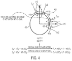
- FIG. 4 shows an example arrangement of a first plurality of actuators 410 operable to maintain the vibrating member 405 of the CVG to vibrate at a constant amplitude in a first vibration mode (AGC) and a second plurality of actuators 415 operable to offset the force due to the Coriolis effect caused by rotation of the CVG about the z-axis (axis of rotation) (FTR).
- AAC first vibration mode
- FTR axis of rotation
- the vibrating member 405 is in the form of a ring; however, other arrangements may be used.
- the arrangement is shown with respect to a coordinate system, where +x to the right hand side of the figure is the drive axis, +y in the upward direction is the sense axis, and +z is the axis of rotation and is out of the page.
- actuators 410a, 410b are shown in FIG. 4 merely for ease of explanation. Similarly, two actuators 415a, 415b of the second plurality of actuators 415 is also shown; however, the first plurality of actuators 410 and the second plurality of actuators 415 can include more than two actuators depending on the particular application and requirements of the gyroscope.
- Actuators 410a, 410b are arranged about and offset from the drive axis.
- actuator 410a can be offset from the drive axis by an angular distance p .
- the other actuators 410b, 415a, and 415b can be similarly offset from either the drive or sense axis by p .
- the voltage along the drive axis can be measured by sensor (pickoff for drive axis (AGC)) 420 and the voltage along the sense axis can be measured by sensor (pickoff for sense axis (FTR)) 425.
- the voltage that is applied to each actuator 410a, 410b of the first plurality of actuators 410, and thus the force ( f x ) to maintain the vibrational mode of the vibrating member in the AGC may not be evenly distributed between each of the actuators 410a, 410b. Therefore, the voltage supplied to each actuator 410a, 410b, and thus the ACG for each actuator f x1 , f x2 may need to be continuously monitored and controlled.
- a first weighing factor ⁇ can be used to adjust the voltage supplied to each actuator 410a, 410b.
- the voltage that is applied to each actuator 415a, 415b of the second plurality of actuators 415, and thus the force to rebalance ( f y ) and offset the Coriolis force produced by rotation of the CVG about the axis of rotation may not be evenly distributed between each of the actuators 415a, 415b. Therefore, the voltage supplied to each actuator 415a, 415b, and thus the FTR for each actuator f y1 , f y2 may also need to be continuously monitored and controlled.
- a second weighing factor ⁇ can be used to adjust the voltage supplied to each actuator 415a, 415b.
- FIG. 5 shows an example closed loop control loop for CVG control with distributed actuation to at least reduce and potentially eliminate the effect of actuation/pickoff misalignment according to the present teachings.
- the CVG receives a first set of inputs related to the automatic gain control (AGC) that is applied to a first plurality of actuators to maintain the vibrating member of the CVG to vibrate at a constant amplitude in a first vibration mode ( ⁇ 1 ) and a second set of inputs related to the force to rebalance (FTR) that is applied to a second plurality of actuators to offset the force due to the Coriolis effect caused by rotation of the CVG about the z-axis (axis of rotation).
- AGC automatic gain control
- FTR force to rebalance
- the first set of inputs, 505a, 505b, and 505n are voltages that are applied to drive actuators 405a and 405b (actuator for input 505n not shown), as shown in FIG. 4 , to produce a force to cause vibrating member of CVG 525 to vibrate in a first vibration mode ( ⁇ 1 ).
- the total force along the x-axis ( f x ) produced by the total of each actuator 405a and 405b can be modified by a corresponding weighting factor ( ⁇ 1 , ⁇ 2 , ..., ⁇ n ) to yield the voltage to cause a force, 510a, 510b, 510n, for each actuator at 405a and 405b to maintain a constant amplitude of the first vibration mode ( ⁇ 1 ).
- the second set of inputs, 515a, 515b, and 515n are voltages that are applied to sense actuators 415a and 415b (actuator for input 515n not shown), as shown in FIG. 4 , to produce a force to counter the force produced by the Coriolis effect that causes vibrating member to vibrate in a second vibration mode ( ⁇ 2 ) when subject to a rotation about the z-axis.
- the total counter-balancing force along the y-axis ( f y ) provided to the total of each actuator 415a and 415b (inputs 515a, 515b, and 515n) can be modified by a corresponding weighting factor ( ⁇ 1 , ⁇ 2 , ..., ⁇ n ) to yield the voltage to produce a counter-balancing force, 520a, 520b, 520n, for each actuator at 415a and 415b, to maintain a constant amplitude of the second vibration mode ( ⁇ 2 ).
- a first switch 570 and a second switch 575 can be arranged to receive and switch the output voltages from 530 and 540 to provide the mode switching functionality, as described in FIG. 6A
- voltage 530 is measured at pickoff 420 for drive axis and is provided to AGC 535 to be provided as inputs in 505a, 505b, 505n.
- a voltage 540 is measured at pickoff 425 for sense axis and is provided to FTR 545 to be provided as inputs in 515a, 515b, 515n. If the phase of the voltage 530 measured at pickoff for drive axis is out of phase, a phase module 550 can correct for phase offsets in voltage 430.
- Demodulation module 555 obtains the phase information from phase module 550 and the voltage from FTR 545 to produce a demodulated voltage that is then filtered by filter 560. The angular velocity of the CVG can then be obtained and outputted 565.
- the sense actuation/pickoff misalignment can be similarly obtained by mode reversing technique where the drive angles are switched by 90°.
- the misalignment is b : FTR mod ⁇ - ⁇ 1 ⁇ sin 2 ⁇ ⁇ + 2 b ⁇ + 2 k ⁇
- the AGC control
- FIGS. 6A - 6D show an example mode switching for the drive and sense axes of the CVG that can be used to correct for 2 nd mode actuation/pickoff misalignment, according to the present teachings.
- FIG. 6A shows the first vibration mode ⁇ 1 (AGC) along the drive axis and
- FIG. 6B show the second vibration mode ⁇ 2 (FTR) along the sense axis.
- the first plurality of actuators 410 and the second plurality of actuators 415 can be reversed, such that the second mode of vibration ⁇ 2 (FTR) is along the drive axis, as shown in FIG. 6C , and the first mode of vibration ⁇ 1 is along the sense axis, as shown in FIG. 6D .
- a first control signal can be obtained from a controller to provide a voltage sufficient to cause and maintain the vibratory member to vibrate in a first mode of oscillation.
- a voltage can then be detected based on a second mode of oscillation of the vibratory member caused by a rotation of the CVG about an axis of rotation.
- a counter-balancing signal can then be provided that is sufficient to null the voltage based on the second mode of oscillation.
- a rate of the rotation of the CVG can then be determined based, in part, on the counter-balancing voltage.
Landscapes
- Engineering & Computer Science (AREA)
- Physics & Mathematics (AREA)
- General Physics & Mathematics (AREA)
- Radar, Positioning & Navigation (AREA)
- Remote Sensing (AREA)
- Signal Processing (AREA)
- Manufacturing & Machinery (AREA)
- Gyroscopes (AREA)
Applications Claiming Priority (1)
| Application Number | Priority Date | Filing Date | Title |
|---|---|---|---|
| US14/594,893 US9709399B2 (en) | 2015-01-12 | 2015-01-12 | Approach for control redistribution of coriolis vibratory gyroscope (CVG) for performance improvement |
Publications (3)
| Publication Number | Publication Date |
|---|---|
| EP3043146A2 true EP3043146A2 (de) | 2016-07-13 |
| EP3043146A3 EP3043146A3 (de) | 2016-08-24 |
| EP3043146B1 EP3043146B1 (de) | 2019-11-06 |
Family
ID=55072587
Family Applications (1)
| Application Number | Title | Priority Date | Filing Date |
|---|---|---|---|
| EP16150710.8A Active EP3043146B1 (de) | 2015-01-12 | 2016-01-11 | Ansatz zur steuerungsumverteilung eines coriolis-schwingungsgyroskops ("cvg") zur leistungsverbesserung |
Country Status (5)
| Country | Link |
|---|---|
| US (1) | US9709399B2 (de) |
| EP (1) | EP3043146B1 (de) |
| JP (1) | JP6732453B2 (de) |
| KR (1) | KR102381898B1 (de) |
| CN (1) | CN105783901B (de) |
Cited By (3)
| Publication number | Priority date | Publication date | Assignee | Title |
|---|---|---|---|---|
| CN107843269A (zh) * | 2017-09-30 | 2018-03-27 | 中国人民解放军国防科技大学 | 一种筛选圆柱壳体振动陀螺谐振子的方法和装置 |
| CN116539065A (zh) * | 2023-05-06 | 2023-08-04 | 廊坊市小磁怪科技有限公司 | 一种陀螺测斜仪的标定修正方法及陀螺测斜仪 |
| EP4300039A3 (de) * | 2022-07-01 | 2024-01-10 | Analog Devices, Inc. | Synchronisiertes massengyroskop mit voller symmetrie und drehbarkeit |
Families Citing this family (1)
| Publication number | Priority date | Publication date | Assignee | Title |
|---|---|---|---|---|
| CN108507556B (zh) * | 2018-03-19 | 2020-04-07 | 中国人民解放军国防科技大学 | 圆柱壳体陀螺谐振子品质因数不均匀的修调方法和装置 |
Family Cites Families (21)
| Publication number | Priority date | Publication date | Assignee | Title |
|---|---|---|---|---|
| US5616864A (en) * | 1995-02-22 | 1997-04-01 | Delco Electronics Corp. | Method and apparatus for compensation of micromachined sensors |
| US5652374A (en) * | 1995-07-10 | 1997-07-29 | Delco Electronics Corp. | Method and apparatus for detecting failure in vibrating sensors |
| JP3489487B2 (ja) * | 1998-10-23 | 2004-01-19 | トヨタ自動車株式会社 | 角速度検出装置 |
| JP2001021362A (ja) * | 1999-07-12 | 2001-01-26 | Japan Aviation Electronics Industry Ltd | クローズドループ制御リング共振型振動ジャイロ |
| GB0001294D0 (en) * | 2000-01-20 | 2000-03-08 | British Aerospace | Multi-axis sensing device |
| DE10317158B4 (de) * | 2003-04-14 | 2007-05-10 | Litef Gmbh | Verfahren zur Ermittlung eines Nullpunktfehlers in einem Corioliskreisel |
| US7565839B2 (en) * | 2005-08-08 | 2009-07-28 | Northrop Grumman Guidance And Electronics Company, Inc. | Bias and quadrature reduction in class II coriolis vibratory gyros |
| US7188523B2 (en) * | 2005-08-08 | 2007-03-13 | Northrop Grumman Corporation | Vibrating mass gyroscope and method for minimizing bias errors therein |
| US7617727B2 (en) * | 2006-04-18 | 2009-11-17 | Watson Industries, Inc. | Vibrating inertial rate sensor utilizing split or skewed operational elements |
| US7526957B2 (en) * | 2006-04-18 | 2009-05-05 | Watson Industries, Inc. | Vibrating inertial rate sensor utilizing skewed drive or sense elements |
| US7444868B2 (en) * | 2006-06-29 | 2008-11-04 | Honeywell International Inc. | Force rebalancing for MEMS inertial sensors using time-varying voltages |
| US7912664B2 (en) * | 2008-09-11 | 2011-03-22 | Northrop Grumman Guidance And Electronics Company, Inc. | Self calibrating gyroscope system |
| US8011246B2 (en) | 2008-09-22 | 2011-09-06 | Northrop Grumman Guidance And Electronics Company, Inc. | Apparatus and method for self-calibration of coriolis vibratory gyroscope |
| EP2177875A3 (de) * | 2008-10-14 | 2013-04-24 | Watson Industries, Inc. | Schwingendes Strukturgyroskop mit Quadratursteuerung |
| US8393212B2 (en) * | 2009-04-01 | 2013-03-12 | The Boeing Company | Environmentally robust disc resonator gyroscope |
| KR101218991B1 (ko) * | 2010-08-06 | 2013-01-07 | 삼성전기주식회사 | 자이로 센서 구동 장치 |
| US9417066B2 (en) * | 2012-01-11 | 2016-08-16 | The Boeing Company | Electronic bias compensation for a gyroscope |
| FI124624B (en) * | 2012-06-29 | 2014-11-14 | Murata Manufacturing Co | Improved oscillating gyroscope |
| CN103322995B (zh) * | 2013-06-20 | 2016-04-13 | 上海交通大学 | 压电驱动静电检测体声波谐振三轴微陀螺及其制备方法 |
| CN106461394A (zh) * | 2014-06-26 | 2017-02-22 | 路梅戴尼科技公司 | 用于从非线性周期信号确定旋转的系统和方法 |
| US9534897B2 (en) * | 2015-01-12 | 2017-01-03 | The Boeing Company | High bandwidth Coriolis vibratory gyroscope (CVG) with in-situ bias self-calibration |
-
2015
- 2015-01-12 US US14/594,893 patent/US9709399B2/en active Active
- 2015-12-30 KR KR1020150189932A patent/KR102381898B1/ko active Active
-
2016
- 2016-01-04 CN CN201610001315.7A patent/CN105783901B/zh active Active
- 2016-01-05 JP JP2016000472A patent/JP6732453B2/ja active Active
- 2016-01-11 EP EP16150710.8A patent/EP3043146B1/de active Active
Non-Patent Citations (1)
| Title |
|---|
| None |
Cited By (6)
| Publication number | Priority date | Publication date | Assignee | Title |
|---|---|---|---|---|
| CN107843269A (zh) * | 2017-09-30 | 2018-03-27 | 中国人民解放军国防科技大学 | 一种筛选圆柱壳体振动陀螺谐振子的方法和装置 |
| CN107843269B (zh) * | 2017-09-30 | 2019-11-08 | 中国人民解放军国防科技大学 | 一种筛选圆柱壳体振动陀螺谐振子的方法和装置 |
| EP4300039A3 (de) * | 2022-07-01 | 2024-01-10 | Analog Devices, Inc. | Synchronisiertes massengyroskop mit voller symmetrie und drehbarkeit |
| US12596006B2 (en) | 2022-07-01 | 2026-04-07 | Analog Devices, Inc. | Synchronized mass gyroscope with full symmetry and turnability |
| CN116539065A (zh) * | 2023-05-06 | 2023-08-04 | 廊坊市小磁怪科技有限公司 | 一种陀螺测斜仪的标定修正方法及陀螺测斜仪 |
| CN116539065B (zh) * | 2023-05-06 | 2025-09-26 | 朝阳上为软件科技有限公司 | 一种陀螺测斜仪的标定修正方法及陀螺测斜仪 |
Also Published As
| Publication number | Publication date |
|---|---|
| EP3043146A3 (de) | 2016-08-24 |
| JP2016130731A (ja) | 2016-07-21 |
| US20160202059A1 (en) | 2016-07-14 |
| CN105783901B (zh) | 2020-12-04 |
| CN105783901A (zh) | 2016-07-20 |
| EP3043146B1 (de) | 2019-11-06 |
| KR102381898B1 (ko) | 2022-03-31 |
| KR20160086747A (ko) | 2016-07-20 |
| JP6732453B2 (ja) | 2020-07-29 |
| US9709399B2 (en) | 2017-07-18 |
Similar Documents
| Publication | Publication Date | Title |
|---|---|---|
| EP3043145B1 (de) | Coriolis vibrationskreisel (cvg) mit hoher bandbreite mit in-situ-vorspannungsselbstkalibrierung | |
| US20230324176A1 (en) | Drive and sense balanced, semi-coupled 3-axis gyroscope | |
| KR101178692B1 (ko) | 코리올리 자이로스코프 | |
| EP3056858B1 (de) | Schwungmasse-gyroskopsysteme und verfahren | |
| US20220326045A1 (en) | Demodulation phase calibration using external input | |
| EP3249355B1 (de) | Systeme und verfahren zur bias-unterdrückung in einem nicht degenerierten mems-sensor | |
| EP3043146A2 (de) | Ansatz zur steuerungsumverteilung eines coriolis-schwingungsgyroskops ("cvg") zur leistungsverbesserung | |
| CN114858184A (zh) | 一种半球谐振子参数辨识方法 | |
| EP3312558A1 (de) | Halbkugelförmiges resonatorgyroskop | |
| EP2615416A2 (de) | Elektronische Vorspannkompensation für ein Gyroskop | |
| US10082404B1 (en) | Electronic self calibration design for disk resonator gyroscopes using electrode time multiplexing | |
| CN114076593B (zh) | 改进的惯性传感器 | |
| JP6704443B2 (ja) | 振動マスジャイロスコープシステム | |
| GB2597041A (en) | Improved inertial sensor | |
| RU2178548C1 (ru) | Микромеханический вибрационный гироскоп | |
| EP3330665A2 (de) | Resonatorkreisel mit dualem vibrationsmuster | |
| US20250297857A1 (en) | Gyroscopic measurement method and sensor | |
| Maslov et al. | Development of methods for identification of nonlinear mathematical model parameters of solid-state wave gyroscope | |
| US20250297859A1 (en) | Gyroscopic measurement method and sensor | |
| Chi et al. | MEMS gyroscope control systems for direct angle measurements | |
| US12492901B2 (en) | Multi-mode, mode-matched, mems-based Coriolis vibratory gyroscope | |
| KR100771492B1 (ko) | 진동형 마이크로 자이로스코프를 이용한 자세각 직접측정제어방법 | |
| US12584742B2 (en) | Method for correcting the measurement from a vibrating angular inertial sensor | |
| Trung Giap | Analysis of Error Mechanisms of Vibrating Gyroscopes Operating in a Slowly Changing Environment |
Legal Events
| Date | Code | Title | Description |
|---|---|---|---|
| PUAI | Public reference made under article 153(3) epc to a published international application that has entered the european phase |
Free format text: ORIGINAL CODE: 0009012 |
|
| 17P | Request for examination filed |
Effective date: 20160111 |
|
| AK | Designated contracting states |
Kind code of ref document: A2 Designated state(s): AL AT BE BG CH CY CZ DE DK EE ES FI FR GB GR HR HU IE IS IT LI LT LU LV MC MK MT NL NO PL PT RO RS SE SI SK SM TR |
|
| AX | Request for extension of the european patent |
Extension state: BA ME |
|
| PUAL | Search report despatched |
Free format text: ORIGINAL CODE: 0009013 |
|
| AK | Designated contracting states |
Kind code of ref document: A3 Designated state(s): AL AT BE BG CH CY CZ DE DK EE ES FI FR GB GR HR HU IE IS IT LI LT LU LV MC MK MT NL NO PL PT RO RS SE SI SK SM TR |
|
| AX | Request for extension of the european patent |
Extension state: BA ME |
|
| RIC1 | Information provided on ipc code assigned before grant |
Ipc: G01C 19/5776 20120101AFI20160718BHEP |
|
| STAA | Information on the status of an ep patent application or granted ep patent |
Free format text: STATUS: REQUEST FOR EXAMINATION WAS MADE |
|
| STAA | Information on the status of an ep patent application or granted ep patent |
Free format text: STATUS: EXAMINATION IS IN PROGRESS |
|
| 17Q | First examination report despatched |
Effective date: 20180329 |
|
| REG | Reference to a national code |
Ref country code: DE Ref legal event code: R079 Ref document number: 602016023562 Country of ref document: DE Free format text: PREVIOUS MAIN CLASS: G01C0019577600 Ipc: G01C0019560000 |
|
| RIC1 | Information provided on ipc code assigned before grant |
Ipc: G01C 19/5719 20120101ALI20190131BHEP Ipc: G01C 19/5705 20120101ALI20190131BHEP Ipc: G01C 19/5726 20120101ALI20190131BHEP Ipc: G01C 19/5776 20120101ALI20190131BHEP Ipc: G01C 19/56 20120101AFI20190131BHEP |
|
| GRAP | Despatch of communication of intention to grant a patent |
Free format text: ORIGINAL CODE: EPIDOSNIGR1 |
|
| STAA | Information on the status of an ep patent application or granted ep patent |
Free format text: STATUS: GRANT OF PATENT IS INTENDED |
|
| INTG | Intention to grant announced |
Effective date: 20190520 |
|
| GRAS | Grant fee paid |
Free format text: ORIGINAL CODE: EPIDOSNIGR3 |
|
| GRAA | (expected) grant |
Free format text: ORIGINAL CODE: 0009210 |
|
| STAA | Information on the status of an ep patent application or granted ep patent |
Free format text: STATUS: THE PATENT HAS BEEN GRANTED |
|
| AK | Designated contracting states |
Kind code of ref document: B1 Designated state(s): AL AT BE BG CH CY CZ DE DK EE ES FI FR GB GR HR HU IE IS IT LI LT LU LV MC MK MT NL NO PL PT RO RS SE SI SK SM TR |
|
| REG | Reference to a national code |
Ref country code: GB Ref legal event code: FG4D |
|
| REG | Reference to a national code |
Ref country code: CH Ref legal event code: EP Ref country code: AT Ref legal event code: REF Ref document number: 1199351 Country of ref document: AT Kind code of ref document: T Effective date: 20191115 |
|
| REG | Reference to a national code |
Ref country code: IE Ref legal event code: FG4D |
|
| REG | Reference to a national code |
Ref country code: DE Ref legal event code: R096 Ref document number: 602016023562 Country of ref document: DE |
|
| REG | Reference to a national code |
Ref country code: NL Ref legal event code: MP Effective date: 20191106 |
|
| REG | Reference to a national code |
Ref country code: LT Ref legal event code: MG4D |
|
| PG25 | Lapsed in a contracting state [announced via postgrant information from national office to epo] |
Ref country code: LV Free format text: LAPSE BECAUSE OF FAILURE TO SUBMIT A TRANSLATION OF THE DESCRIPTION OR TO PAY THE FEE WITHIN THE PRESCRIBED TIME-LIMIT Effective date: 20191106 Ref country code: SE Free format text: LAPSE BECAUSE OF FAILURE TO SUBMIT A TRANSLATION OF THE DESCRIPTION OR TO PAY THE FEE WITHIN THE PRESCRIBED TIME-LIMIT Effective date: 20191106 Ref country code: PT Free format text: LAPSE BECAUSE OF FAILURE TO SUBMIT A TRANSLATION OF THE DESCRIPTION OR TO PAY THE FEE WITHIN THE PRESCRIBED TIME-LIMIT Effective date: 20200306 Ref country code: BG Free format text: LAPSE BECAUSE OF FAILURE TO SUBMIT A TRANSLATION OF THE DESCRIPTION OR TO PAY THE FEE WITHIN THE PRESCRIBED TIME-LIMIT Effective date: 20200206 Ref country code: FI Free format text: LAPSE BECAUSE OF FAILURE TO SUBMIT A TRANSLATION OF THE DESCRIPTION OR TO PAY THE FEE WITHIN THE PRESCRIBED TIME-LIMIT Effective date: 20191106 Ref country code: NO Free format text: LAPSE BECAUSE OF FAILURE TO SUBMIT A TRANSLATION OF THE DESCRIPTION OR TO PAY THE FEE WITHIN THE PRESCRIBED TIME-LIMIT Effective date: 20200206 Ref country code: GR Free format text: LAPSE BECAUSE OF FAILURE TO SUBMIT A TRANSLATION OF THE DESCRIPTION OR TO PAY THE FEE WITHIN THE PRESCRIBED TIME-LIMIT Effective date: 20200207 Ref country code: PL Free format text: LAPSE BECAUSE OF FAILURE TO SUBMIT A TRANSLATION OF THE DESCRIPTION OR TO PAY THE FEE WITHIN THE PRESCRIBED TIME-LIMIT Effective date: 20191106 Ref country code: NL Free format text: LAPSE BECAUSE OF FAILURE TO SUBMIT A TRANSLATION OF THE DESCRIPTION OR TO PAY THE FEE WITHIN THE PRESCRIBED TIME-LIMIT Effective date: 20191106 Ref country code: LT Free format text: LAPSE BECAUSE OF FAILURE TO SUBMIT A TRANSLATION OF THE DESCRIPTION OR TO PAY THE FEE WITHIN THE PRESCRIBED TIME-LIMIT Effective date: 20191106 |
|
| PG25 | Lapsed in a contracting state [announced via postgrant information from national office to epo] |
Ref country code: RS Free format text: LAPSE BECAUSE OF FAILURE TO SUBMIT A TRANSLATION OF THE DESCRIPTION OR TO PAY THE FEE WITHIN THE PRESCRIBED TIME-LIMIT Effective date: 20191106 Ref country code: HR Free format text: LAPSE BECAUSE OF FAILURE TO SUBMIT A TRANSLATION OF THE DESCRIPTION OR TO PAY THE FEE WITHIN THE PRESCRIBED TIME-LIMIT Effective date: 20191106 Ref country code: IS Free format text: LAPSE BECAUSE OF FAILURE TO SUBMIT A TRANSLATION OF THE DESCRIPTION OR TO PAY THE FEE WITHIN THE PRESCRIBED TIME-LIMIT Effective date: 20200306 |
|
| PG25 | Lapsed in a contracting state [announced via postgrant information from national office to epo] |
Ref country code: AL Free format text: LAPSE BECAUSE OF FAILURE TO SUBMIT A TRANSLATION OF THE DESCRIPTION OR TO PAY THE FEE WITHIN THE PRESCRIBED TIME-LIMIT Effective date: 20191106 |
|
| PG25 | Lapsed in a contracting state [announced via postgrant information from national office to epo] |
Ref country code: ES Free format text: LAPSE BECAUSE OF FAILURE TO SUBMIT A TRANSLATION OF THE DESCRIPTION OR TO PAY THE FEE WITHIN THE PRESCRIBED TIME-LIMIT Effective date: 20191106 Ref country code: CZ Free format text: LAPSE BECAUSE OF FAILURE TO SUBMIT A TRANSLATION OF THE DESCRIPTION OR TO PAY THE FEE WITHIN THE PRESCRIBED TIME-LIMIT Effective date: 20191106 Ref country code: RO Free format text: LAPSE BECAUSE OF FAILURE TO SUBMIT A TRANSLATION OF THE DESCRIPTION OR TO PAY THE FEE WITHIN THE PRESCRIBED TIME-LIMIT Effective date: 20191106 Ref country code: DK Free format text: LAPSE BECAUSE OF FAILURE TO SUBMIT A TRANSLATION OF THE DESCRIPTION OR TO PAY THE FEE WITHIN THE PRESCRIBED TIME-LIMIT Effective date: 20191106 Ref country code: EE Free format text: LAPSE BECAUSE OF FAILURE TO SUBMIT A TRANSLATION OF THE DESCRIPTION OR TO PAY THE FEE WITHIN THE PRESCRIBED TIME-LIMIT Effective date: 20191106 |
|
| REG | Reference to a national code |
Ref country code: DE Ref legal event code: R097 Ref document number: 602016023562 Country of ref document: DE |
|
| REG | Reference to a national code |
Ref country code: AT Ref legal event code: MK05 Ref document number: 1199351 Country of ref document: AT Kind code of ref document: T Effective date: 20191106 |
|
| PG25 | Lapsed in a contracting state [announced via postgrant information from national office to epo] |
Ref country code: SK Free format text: LAPSE BECAUSE OF FAILURE TO SUBMIT A TRANSLATION OF THE DESCRIPTION OR TO PAY THE FEE WITHIN THE PRESCRIBED TIME-LIMIT Effective date: 20191106 Ref country code: SM Free format text: LAPSE BECAUSE OF FAILURE TO SUBMIT A TRANSLATION OF THE DESCRIPTION OR TO PAY THE FEE WITHIN THE PRESCRIBED TIME-LIMIT Effective date: 20191106 Ref country code: MC Free format text: LAPSE BECAUSE OF FAILURE TO SUBMIT A TRANSLATION OF THE DESCRIPTION OR TO PAY THE FEE WITHIN THE PRESCRIBED TIME-LIMIT Effective date: 20191106 |
|
| REG | Reference to a national code |
Ref country code: CH Ref legal event code: PL |
|
| PLBE | No opposition filed within time limit |
Free format text: ORIGINAL CODE: 0009261 |
|
| STAA | Information on the status of an ep patent application or granted ep patent |
Free format text: STATUS: NO OPPOSITION FILED WITHIN TIME LIMIT |
|
| 26N | No opposition filed |
Effective date: 20200807 |
|
| REG | Reference to a national code |
Ref country code: BE Ref legal event code: MM Effective date: 20200131 |
|
| PG25 | Lapsed in a contracting state [announced via postgrant information from national office to epo] |
Ref country code: LU Free format text: LAPSE BECAUSE OF NON-PAYMENT OF DUE FEES Effective date: 20200111 |
|
| PG25 | Lapsed in a contracting state [announced via postgrant information from national office to epo] |
Ref country code: LI Free format text: LAPSE BECAUSE OF NON-PAYMENT OF DUE FEES Effective date: 20200131 Ref country code: SI Free format text: LAPSE BECAUSE OF FAILURE TO SUBMIT A TRANSLATION OF THE DESCRIPTION OR TO PAY THE FEE WITHIN THE PRESCRIBED TIME-LIMIT Effective date: 20191106 Ref country code: CH Free format text: LAPSE BECAUSE OF NON-PAYMENT OF DUE FEES Effective date: 20200131 Ref country code: AT Free format text: LAPSE BECAUSE OF FAILURE TO SUBMIT A TRANSLATION OF THE DESCRIPTION OR TO PAY THE FEE WITHIN THE PRESCRIBED TIME-LIMIT Effective date: 20191106 Ref country code: BE Free format text: LAPSE BECAUSE OF NON-PAYMENT OF DUE FEES Effective date: 20200131 |
|
| PG25 | Lapsed in a contracting state [announced via postgrant information from national office to epo] |
Ref country code: IT Free format text: LAPSE BECAUSE OF FAILURE TO SUBMIT A TRANSLATION OF THE DESCRIPTION OR TO PAY THE FEE WITHIN THE PRESCRIBED TIME-LIMIT Effective date: 20191106 Ref country code: IE Free format text: LAPSE BECAUSE OF NON-PAYMENT OF DUE FEES Effective date: 20200111 |
|
| PG25 | Lapsed in a contracting state [announced via postgrant information from national office to epo] |
Ref country code: TR Free format text: LAPSE BECAUSE OF FAILURE TO SUBMIT A TRANSLATION OF THE DESCRIPTION OR TO PAY THE FEE WITHIN THE PRESCRIBED TIME-LIMIT Effective date: 20191106 Ref country code: MT Free format text: LAPSE BECAUSE OF FAILURE TO SUBMIT A TRANSLATION OF THE DESCRIPTION OR TO PAY THE FEE WITHIN THE PRESCRIBED TIME-LIMIT Effective date: 20191106 Ref country code: CY Free format text: LAPSE BECAUSE OF FAILURE TO SUBMIT A TRANSLATION OF THE DESCRIPTION OR TO PAY THE FEE WITHIN THE PRESCRIBED TIME-LIMIT Effective date: 20191106 |
|
| PG25 | Lapsed in a contracting state [announced via postgrant information from national office to epo] |
Ref country code: MK Free format text: LAPSE BECAUSE OF FAILURE TO SUBMIT A TRANSLATION OF THE DESCRIPTION OR TO PAY THE FEE WITHIN THE PRESCRIBED TIME-LIMIT Effective date: 20191106 |
|
| P01 | Opt-out of the competence of the unified patent court (upc) registered |
Effective date: 20230516 |
|
| PGFP | Annual fee paid to national office [announced via postgrant information from national office to epo] |
Ref country code: GB Payment date: 20260127 Year of fee payment: 11 |
|
| PGFP | Annual fee paid to national office [announced via postgrant information from national office to epo] |
Ref country code: DE Payment date: 20260128 Year of fee payment: 11 |
|
| PGFP | Annual fee paid to national office [announced via postgrant information from national office to epo] |
Ref country code: FR Payment date: 20260126 Year of fee payment: 11 |