EP3043221A1 - Contact pouvant être actionné manuellement, alimenté par un bus, et un module de communication - Google Patents
Contact pouvant être actionné manuellement, alimenté par un bus, et un module de communication Download PDFInfo
- Publication number
- EP3043221A1 EP3043221A1 EP15202019.4A EP15202019A EP3043221A1 EP 3043221 A1 EP3043221 A1 EP 3043221A1 EP 15202019 A EP15202019 A EP 15202019A EP 3043221 A1 EP3043221 A1 EP 3043221A1
- Authority
- EP
- European Patent Office
- Prior art keywords
- switch
- circuit board
- printed circuit
- unit module
- module
- Prior art date
- Legal status (The legal status is an assumption and is not a legal conclusion. Google has not performed a legal analysis and makes no representation as to the accuracy of the status listed.)
- Granted
Links
Images


Classifications
-
- G—PHYSICS
- G05—CONTROLLING; REGULATING
- G05B—CONTROL OR REGULATING SYSTEMS IN GENERAL; FUNCTIONAL ELEMENTS OF SUCH SYSTEMS; MONITORING OR TESTING ARRANGEMENTS FOR SUCH SYSTEMS OR ELEMENTS
- G05B19/00—Program-control systems
- G05B19/02—Program-control systems electric
- G05B19/04—Program control other than numerical control, i.e. in sequence controllers or logic controllers
- G05B19/05—Programmable logic controllers, e.g. simulating logic interconnections of signals according to ladder diagrams or function charts
-
- H—ELECTRICITY
- H02—GENERATION; CONVERSION OR DISTRIBUTION OF ELECTRIC POWER
- H02B—BOARDS, SUBSTATIONS OR SWITCHING ARRANGEMENTS FOR THE SUPPLY OR DISTRIBUTION OF ELECTRIC POWER
- H02B1/00—Frameworks, boards, panels, desks, casings; Details of substations or switching arrangements
- H02B1/26—Casings; Parts thereof or accessories therefor
- H02B1/30—Cabinet-type casings; Parts thereof or accessories therefor
- H02B1/32—Mounting of devices therein
-
- H—ELECTRICITY
- H01—ELECTRIC ELEMENTS
- H01H—ELECTRIC SWITCHES; RELAYS; SELECTORS; EMERGENCY PROTECTIVE DEVICES
- H01H13/00—Switches having rectilinearly-movable operating part or parts adapted for pushing or pulling in one direction only, e.g. push-button switch
- H01H13/70—Switches having rectilinearly-movable operating part or parts adapted for pushing or pulling in one direction only, e.g. push-button switch having a plurality of operating members associated with different sets of contacts, e.g. keyboard
- H01H13/81—Switches having rectilinearly-movable operating part or parts adapted for pushing or pulling in one direction only, e.g. push-button switch having a plurality of operating members associated with different sets of contacts, e.g. keyboard characterised by electrical connections to external devices
-
- H—ELECTRICITY
- H01—ELECTRIC ELEMENTS
- H01H—ELECTRIC SWITCHES; RELAYS; SELECTORS; EMERGENCY PROTECTIVE DEVICES
- H01H9/00—Details of switching devices, not covered by groups H01H1/00 - H01H7/00
- H01H9/16—Indicators for switching condition, e.g. "on" or "off"
- H01H9/167—Circuits for remote indication
-
- H—ELECTRICITY
- H03—ELECTRONIC CIRCUITRY
- H03K—PULSE TECHNIQUE
- H03K17/00—Electronic switching or gating, i.e. not by contact-making and –breaking
- H03K17/94—Electronic switching or gating, i.e. not by contact-making and –breaking characterised by the way in which the control signals are generated
- H03K17/965—Switches controlled by moving an element forming part of the switch
- H03K17/968—Switches controlled by moving an element forming part of the switch using opto-electronic devices
-
- H—ELECTRICITY
- H05—ELECTRIC TECHNIQUES NOT OTHERWISE PROVIDED FOR
- H05K—PRINTED CIRCUITS; CASINGS OR CONSTRUCTIONAL DETAILS OF ELECTRIC APPARATUS; MANUFACTURE OF ASSEMBLAGES OF ELECTRICAL COMPONENTS
- H05K7/00—Constructional details common to different types of electric apparatus
- H05K7/14—Mounting supporting structure in casing or on frame or rack
- H05K7/1462—Mounting supporting structure in casing or on frame or rack for programmable logic controllers [PLC] for automation or industrial process control
- H05K7/1468—Mechanical features of input/output (I/O) modules
- H05K7/1471—Modules for controlling actuators
-
- G—PHYSICS
- G05—CONTROLLING; REGULATING
- G05B—CONTROL OR REGULATING SYSTEMS IN GENERAL; FUNCTIONAL ELEMENTS OF SUCH SYSTEMS; MONITORING OR TESTING ARRANGEMENTS FOR SUCH SYSTEMS OR ELEMENTS
- G05B2219/00—Program-control systems
- G05B2219/10—Plc systems
- G05B2219/11—Plc I-O input output
- G05B2219/1133—Sensor actuator, asi, bus, network
-
- G—PHYSICS
- G05—CONTROLLING; REGULATING
- G05B—CONTROL OR REGULATING SYSTEMS IN GENERAL; FUNCTIONAL ELEMENTS OF SUCH SYSTEMS; MONITORING OR TESTING ARRANGEMENTS FOR SUCH SYSTEMS OR ELEMENTS
- G05B2219/00—Program-control systems
- G05B2219/20—Pc systems
- G05B2219/25—Pc structure of the system
- G05B2219/25017—ASI actuator sensor interface, bus, network
-
- H—ELECTRICITY
- H01—ELECTRIC ELEMENTS
- H01H—ELECTRIC SWITCHES; RELAYS; SELECTORS; EMERGENCY PROTECTIVE DEVICES
- H01H2300/00—Orthogonal indexing scheme relating to electric switches, relays, selectors or emergency protective devices covered by H01H
- H01H2300/03—Application domotique, e.g. for house automation, bus connected switches, sensors, loads or intelligent wiring
-
- Y—GENERAL TAGGING OF NEW TECHNOLOGICAL DEVELOPMENTS; GENERAL TAGGING OF CROSS-SECTIONAL TECHNOLOGIES SPANNING OVER SEVERAL SECTIONS OF THE IPC; TECHNICAL SUBJECTS COVERED BY FORMER USPC CROSS-REFERENCE ART COLLECTIONS [XRACs] AND DIGESTS
- Y02—TECHNOLOGIES OR APPLICATIONS FOR MITIGATION OR ADAPTATION AGAINST CLIMATE CHANGE
- Y02B—CLIMATE CHANGE MITIGATION TECHNOLOGIES RELATED TO BUILDINGS, e.g. HOUSING, HOUSE APPLIANCES OR RELATED END-USER APPLICATIONS
- Y02B90/00—Enabling technologies or technologies with a potential or indirect contribution to GHG emissions mitigation
- Y02B90/20—Smart grids as enabling technology in buildings sector
-
- Y—GENERAL TAGGING OF NEW TECHNOLOGICAL DEVELOPMENTS; GENERAL TAGGING OF CROSS-SECTIONAL TECHNOLOGIES SPANNING OVER SEVERAL SECTIONS OF THE IPC; TECHNICAL SUBJECTS COVERED BY FORMER USPC CROSS-REFERENCE ART COLLECTIONS [XRACs] AND DIGESTS
- Y04—INFORMATION OR COMMUNICATION TECHNOLOGIES HAVING AN IMPACT ON OTHER TECHNOLOGY AREAS
- Y04S—SYSTEMS INTEGRATING TECHNOLOGIES RELATED TO POWER NETWORK OPERATION, COMMUNICATION OR INFORMATION TECHNOLOGIES FOR IMPROVING THE ELECTRICAL POWER GENERATION, TRANSMISSION, DISTRIBUTION, MANAGEMENT OR USAGE, i.e. SMART GRIDS
- Y04S20/00—Management or operation of end-user stationary applications or the last stages of power distribution; Controlling, monitoring or operating thereof
- Y04S20/14—Protecting elements, switches, relays or circuit breakers
Definitions
- the present invention relates to automation and control devices, and particularly to bus powered modules and communication modules employing a shared common communications link to activate an output device, and a method of making such modules.
- each of a plurality of manually activated operator interface devices can be used to operate an associated contact block having one or more electrical switches.
- Each contact block is electrically connected to an associated remotely located output device, such as a pilot light, a contactor, an overload relay, or other electrically controllable devices.
- each contact block is electrically connected to an associated input access module, which provides access to the multiplexing communications link over which the status of that particular contact block is conveyed to an associated output access control module.
- the output access control module is electrically connected to an associated output device, which is ultimately controlled by the associated operator interface device at the control panel.
- the input access module is generally placed at an easily accessible location inside the control panel, such as the back wall of the panel enclosure. This is usually some distance away from the contact block. It is also common for a control panel to include a number of pilot lights, each indicating the status of an associated output device controlled by its associated operator interface device.
- pilot lights are actually output devices and therefore require a connection to the common communications link.
- Each pilot light requires a separate output access module and wiring between the output access module and the pilot light.
- the wiring between the contact blocks, pilot lights, and their associated input and output access modules must be of sufficient length to permit cover removal when inspection, maintenance, or trouble shooting is required. This generally requires several feet of wire for each connection.
- Control panels which have a large number of operator interface devices and pilot lights, are difficult to wire and assemble due to the many wires required. Thus, even with the common communications link between input access modules and output access modules, the control panel itself still requires considerable wiring time and material.
- the physical size of the control panel enclosure is also a consideration. For each contact block and pilot light in the control panel, one input or output access module is required.
- the input and output access modules are at least the same size as the contact blocks and pilot lights, and in many cases much larger. Therefore, the volume of the control panel must be of sufficient size to enclose all of the input and output access modules and the wire required for connecting them to their respective contact blocks and pilot lights.
- control panels today often have displays and touch panels, conventional pushbuttons, switches, and light indicator are very important. It is labour intensive and time consuming to adjust and connect them to the control systems e.g. PLC - Programmable Logic Controller etc., even if modern bus technology is used as Actuator Sensor Interface systems.
- the main objective of this invention is to provide solutions to problems related to the labour intensive wiring and assembly problems associated with control panels, while at the same time making trouble-shooting and maintenance of the control panels easier, especially for adjusting and connecting manual switch operator devices e.g. pushbuttons, rotary selectors, key operators, switches, and light indicators to the control panels.
- manual switch operator devices e.g. pushbuttons, rotary selectors, key operators, switches, and light indicators to the control panels.
- control panels flexible, by making it possible to connect different types of manual switch operator devices to the control panels, without requiring additional labour and components.
- control panels are durable.
- the device has a manually actuatable integrated unit module, comprising a switch operator device, which is movable between at least a first and a second position. Further, at least a first electrical switch is mounted on the surface of a first printed circuit board, in such a way that movement of the switch operator between the at least first and second position will cause a change in mode of said at least first electrical switch. Such a change of mode will cause a control signal to be placed on a common communications link for controlling an associated output device.
- At least one communication terminal is mounted on a second printed circuit board that is arranged for handling any first printed circuit board.
- the second printed circuit board has inputs for receiving signals from said at least first electrical switch on said first printed circuit board , and also has outputs for transmitting signals from the communications terminal to output means on said first printed circuit board.
- the inputs are arranged to handle at least a 4-bit word, and the outputs are arranged to handle at least a 4-bit word.
- a particular advantage of the present invention is that the second printed circuit board can be produced in a standardized way, which is cost effective and smart, while the first printed circuit board can be custom made dependant on the manually operable actuators, e.g. pushbutton operators, rotary selectors, key operators, switches, indicators, handles, knobs, joysticks and light indicators that are to be connected to the switch operator device.
- manually operable actuators e.g. pushbutton operators, rotary selectors, key operators, switches, indicators, handles, knobs, joysticks and light indicators that are to be connected to the switch operator device.
- the present invention provides versatility since at least four inputs and at least four outputs are used for communiation between the first printed circuit board and the second printed circuit board, enabling at least 16 different states to be communicated via the inputs and at least 16 different states to be communicated via the outputs.
- the first printed circuit board is enabled to be equipped with electrical switches and output means that each can handle at least 16 different states.
- At least one communication terminal is at least one Actuator Sensor Interface module, being a slave module.
- said at least one slave module is connected to said output device, wherein said output device is a master module in a control system, such as a Programmable Logic Controller or a Microcomputer, controlling in a pre-determined and cyclic way said at least one slave module.
- a control system such as a Programmable Logic Controller or a Microcomputer
- said common communications link is an Actuator Sensor Interface bus.
- the switch operator device includes a manually operable actuator such as e.g. a button with a digital display, a manually operable selector switch, a manually operable key switch, or a manually operable pushbutton.
- a manually operable actuator such as e.g. a button with a digital display, a manually operable selector switch, a manually operable key switch, or a manually operable pushbutton.
- the manually operable actuator includes a pilot light, having a light being determined by said associated output device.
- said switch operator device is connected to a manually operable actuator that comprises an indicator.
- the manually actuatable integrated unit module comprises a rotatable switch knob which can be turned in fixed steps, an encoder plate, adapted to be mechanically movable with the rotable switch knob, and a partially enclosing encoder device.
- the encoder device is arranged to interpret the positon of the encoded plate and thus the setting of the switch knob when the switch knob is turned.
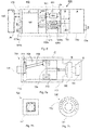
- a typical control panel assembly includes a number of manual switch operator devices, such as a pushbutton operator 101, a rotary selector 102, or a key operator 103. These switch operator devices manually interface with contact blocks, which provide the means to control a number of output devices at locations remote from the control panel assembly 100. It is also common for the control panel assembly 100 to include a number of output devices, for example, pilot lights 104, which normally indicate the status of associated remotely located output devices controlled by the switch operator devices.
- a known control and signalling unit 200 from Schneider Electric comprising pushbuttons 201, switches 202, LED indicators 203 as pilot lights designed for visual signalling all in module A, holders 204 in module B, indication/LED 205, 206 in module C, and contact blocks 207, 208 in module C.
- a new module herein defined as a unit module, will replace module C, i.e. the indications/LED 205, 206 and indication lamp/LED contact blocks 207, 208, and further extend the functionality of the module A and B, i.e. the holder 204, the pushbuttons 201 and switches 202 that are mechanically transforming the power of the hand to the unit module, and the LED indicators 203 that transform visual signals from the unit module to the eye.
- FIG. 3 there is shown a known example of the switch operator device 300 with a pushbutton, which is detachably connected to a communications terminal 306 for the purpose of a bus connection.
- the communications terminal 306 has a logic unit for electrically connecting the control and/or indication device to the bus system. Further, a mechanical connecting means 305, for detachably fixing the communications terminal 306 to two functional elements 304, and electrical connecting means 303, providing the electrical contact between the communication terminal 306 and the two functional elements 304.
- a common communications link 307 electrically connecting the communication terminal 306 to remotely located output devices controlled by the switch operator via the bus system.
- the manual switch operator device 301 in Fig. 3 shown as a pushbutton/switch/indicator 201, 202, 203, in Fig. 2 , is divided into four modules.
- an aspect of the embodiment of the unit module is designed to replace module C and extend the functionality of the modules A and B to include module D. It is a new solution that optimizes wiring and assembly of manually operable switch operators, such as manual actuators to control panels, and extends the possibility to connect different manually operable switch operators and especially multiple switches of different types the same way to existing manual control panels for remotely controlling electrical devices and other types of indicators.
- FIG. 4 there is shown a known Actuator Sensor Interface system 400, the Actuator Sensor Interface, herein defined as AS-interface or AS-I.
- a controller 406 e.g. PLC - Programmable Logic Controller, DCS - Distributed Control System, or a PC (Micro Computer), handling at least one master (M1) 401 controlling the AS-I slaves (S1-S3) 402-404 in the AS-I slave network 407.
- the AS-I slave network 407 is configured and controlled by the master M1 401 that is the interface between the controller 406 and the AS-I slave network 407.
- the master M1 401 continually exchanges information with all slaves S1-S3 402-404 linked to the AS-I bus 405, herein defined as the common communications link, and the controller 406 in a pre-determined and cyclic way. Thereby can the controller 406 have contact with all sensors and control all actuators connected in the AS-I system 400. Further down below it is shown how such an AS-I slave network 407 can be incorporated into embodiments of the unit module, according to the invention, as it is a simple and cheap industrial networking solution. As the person skilled in the art appreciates, other interfaces than AS-I slave networks 407 for industrial networking solutions can be used in the embodiments of the unit model, according to the invention, but can be more complex and expensive.
- AS-I reduces operating costs and offers great flexibility for all automation systems.
- Slaves are managed by a single master M1 401 that interrogates each slave S1-S3 402-404 present on the common communications link 405 in turn and waits for its response.
- the amount of slaves to be mounted to a master is about 62 and each slave has its own address.
- the master M1 401 is query cycling and each slave S1-S3 402-404 is defined by its functions included in the slave, where, according to some aspects, the maximum number of on/off inputs/outputs per slave is four inputs and four outputs.
- the number of remotely located output devices connectable to one AS-I master M1 401 is up to 248 sensors and 248 actuators by two unshielded wires, carrying the power supply for peripherals and logical signals. In most case a controller 406 can handle more than one AS-I master M1 401.
- the AS-Interface slave network 407 is a networking alternative to the hard wiring of field devices.
- the AS-Interface slave network 407 can also be used as a partner network for higher level field bus networks such as Profibus, ProfiNet, and Industrial Ethernet, for whom it offers a low-cost remote input/output solution.
- a gateway is involved or a master module is a distributed module in Profibus, ProfiNet, and Industrial Ethernet node.
- AS-I is used in automation applications, including conveyor control, packaging machines, process control valves, bottling plants, electrical distribution systems, airport baggage carousels, elevators, bottling lines, and food production lines.
- the name Actuator Sensor Interface (AS-I) represents its own concept. Although technically meaning a bus, the term interface shows that it provides a simple program for accessing field sensors and actuators. Traditionally, these connections are made of twisted pairs that connect each actuator and sensor, one by one, to the corresponding controller, typically a PLC.
- FIG. 5a and Fig. 5b an embodiment of the unit module 500, 520, according to the invention is shown from the side 500 and the top 520.
- This exemplary embodiment of the unit module 500, 520, according to the invention can be used for direct replacement of today's control and signalling system, e.g. Schneider Electric Harmony XB4, the module described in Fig. 2 .
- Schneider Electric Harmony XB4 module at least four different components can be replaced by the new unit module 500, 520.
- the unit module 500 being in the form of a connector arrangement, comprises a first circuit board 501 and a second circuit board 502, herein defined as daughter card 501 and main card 502, respectively.
- a communications terminal 511 is mounted, connected to a common communications link 512.
- the communications terminal 511 is an AS-I slave module 511 in an AS-Interface slave network 407 as shown in Fig. 4 .
- the status of the communications terminal 511 is shown by the status indicator 510a-b, according to the AS-I standard, e.g. at least one LED indicator indicates the bus status/ the status of the unit module (the status if active bus, the status if bus is addressed, and status if voltage is supplied).
- the daughter card 501 comprises at least one electrical switch 503a that is controlled by a manual rod device 504 with a slot 505 and handle 506, herein defined as a switch operator device 504-506.
- the switch operator device 504-506 is movable between at least a first and a second position.
- the switch operator device 504-506 can have a return spring 507.
- the switch operator device 504-506 is mechanically operated, e.g. by a pushbutton or switch, not shown.
- the switch operator device 504-506 moves to a position where the slot 505 is positioned such that the electrical switch 503a creates a signal change.
- the return spring 507 gives the pushbutton a resistance when pressing the button in the in-position. The same return spring 507 biases the rod 504 back in position when the pushbutton is pressed in out-position.
- the change of position of the switch operator device 504-506 changes the state of the electrical switch 503a, and in turn changes the state of the level of a signal.
- the state of the signal changes and e.g. the level of the signal rises.
- the signal is no signal when the pushbutton is out and when pressed in, a signal can be detected.
- An example of such signal is a voltage signal.
- no signal is 0 volt, or at least no signal is e.g. between 0 and 0.2 volt, and any voltage above at least 0.5 volt during a pre-determined time is a voltage signal detected.
- a voltage signal can be any signal that can be measured, e.g. a current, a radiation of light or magnetic/electric fields.
- An advantage with detecting a voltage signal is that the signal itself does not have to be converted to a digital signal, "0” or “1”, it can directly be interpreted as a signal or no signal, saving components the need for complex logic circuits for converting a voltage signal into a digital signal, "0” or “1 ", which in turn reduces production cost and reduces the size of the unit module etc.
- An example of an electrical switch 503a-b is a light switch, such a light switch is e.g. a photomicrosensor, and when the slot 505 is in position for a pilot light to be detected, the voltage level rises.
- a photomicrosensor is EE-SX1041 by Omron.
- the pulse width is 10 ⁇ s maximum with a frequency of 100 Hz, forward voltage 1.2 V and maximum 1.5 V. It produces an instantaneous voltage, which is the voltage between two points at a particular moment in time.
- any kind of converter for converting a mechanical movement into an electrical signal can be used, e.g. in its simplest way with a reed switch that is controlled by a moving magnet, the magnet closes the switch depending on the position of the switch operator device 504-506, and a voltage signal can be detected.
- the ways the pushbutton works together with the switch operator device 504-506 and the photomicrosensor 503a-b is only an example of ways the switch operator device 504-506 and photomicrosensor 503a-b can be combined.
- a manual actuator e.g. a joystick function
- the number of light switches 503a-b on the daughter card 501, as well as the number of positions that the switch operator device 504-506 is movable between, are dependent on the type of manual actuators. Further, the number of daughter cards 501 that are connected to the main card 502, as well as the features present on each daughter card, are dependent on the number of switch operator devices 504-506 as well as the type of switch operators. There is at least one switch operator device 504-506 per daughter card 501. In Fig. 5a and Fig. 5b there is shown one switch operator device 504-506 with a bias spring 507, but two light switches 503a and 503b are shown.
- the daughter card 501 is adapted to handle a certain switch operator device 504-506.
- a manually operable actuator comprised in a switch operator device such as e.g. a switch with 16 different positions
- the main card 502 can handle any daughter card 501, which is in turn is adapted for a certain switch operator device 504-506 or actually in turn is adapted for the manually operable actuator, such as e.g. pushbuttons 101, rotary selectors 102, key operators 103, pilot lights 104 in Fig. 1 , or pushbuttons 201, switches 202, LED indicators 203 in Fig. 2 .
- the daughter card 501 is adapted for how to convert the mechanical movement of the manually operable actuator into a signal.
- the main card 502 can be produced in a standardized way, which is cost effective and smart, while the daughter card 501 can be custom made dependant on the manually operable actuators, e.g. pushbutton operators 101, rotary selectors 102, or key operators 103 etc. as shown in Fig. 1 ; or pushbutton/switch/indicator 201, 202, 203, etc. as shown in Fig. 2 , or handles, knobs, joysticks, light indicators that are to be connected to the switch operator device 504-506. Further, in Figs. 5a -b it is shown how the main card 502 is positioned 90 degrees in relation to the daughter card 501.
- the manually operable actuators e.g. pushbutton operators 101, rotary selectors 102, or key operators 103 etc. as shown in Fig. 1 ; or pushbutton/switch/indicator 201, 202, 203, etc. as shown in Fig. 2 , or handles, knobs, joysticks,
- the main card 502 may be positioned relative to the daughter card 501 in other ways than 90 degrees, for example, the main card 502 may be angled more or less than 90 degrees or be arranged parallel with the daughter card 501.
- a light pipe 508 can be mounted and can have Light - Emitting Diodes (LEDs) that can be used as indicators 509.
- LEDs Light - Emitting Diodes
- the AS-I slave network 407 described in Fig. 4 is an exemplary embodiment comprising a communications terminal 620 used in the unit module 600.
- the communications terminal 620 is programmed to be an AS-I slave module, so the main card 602 becomes a slave to the control system 660 (e.g. PLC) that the unit module 600 is connected to.
- the communications terminal 620 being an AS-I slave module 620, and also the main card 602, has four inputs 621 and four outputs 622 that can be directly connected to the daughter card 601.
- the inputs 621 are used for receiving signals 625a from the daughter card 601, for example from electrical switches 603a-b, and the outputs 622 are used for transmitting signals from the communications terminal 620 to the daughter card 601, for example to output means 609 on the daughter card 601.
- the switches 603a-b and the output means 609 will be further described below.
- the four inputs 621 and the four outputs 622 can handle digital information that can be interpreted to be a 4 bit word, which has a numerical value of 0-15 and thereby 16 different states.
- it is sufficient with one communications terminal 620, but for example, in the case where the daughter card needs to manage more than 16 bits for the inputs 621 and the outputs 622, it may be done by arranging two communications terminals (or more) 620.
- the communications terminal may also intself be arranged for handling more than 16 bits for the inputs 621 and the outputs 622.
- a connector can be connected between the daughter card 601 and the main card 602, and then have receiving means as well as transmitting means between the two cards.
- the inputs and the outputs are arranged for serial communication.
- a light switch 603a is controlled by one AS-I slave module 620.
- the AS-I slave module 620 is connected to the common communications link 612, so the signal 661 can be transported to the master of the AS-I network that is in the controller 660 (PLC), and in the controller the signal can be interpreted.
- a signal 661 can go back to the AS-I slave module 620 or modules, and can therefore control the signal state of the outputs means 609 of the light pipe 608 mounted on the daughter card 601 via the communications link 612, via the inputs 621 and outputs 622, to and from the AS-I slave module 620, via connections 623-624 to the light pipe 608, to connections 651 via a holder 650 to output means 609.
- a second pushbutton is mounted to the daughter card 601
- another set of switch operator devices through a second light switch 603b are connected to an input of a second AS-I slave module, not shown, and a further signal can be interpreted by the remote master of the AS-I network by the controller 660 (e.g. PLC).
- the controller 660 e.g. PLC
- FIG. 7a -c an extended use of an embodiment of the unit module, according to the invention is shown.
- a daughter card 710 comprises a switch having a rotatable switch knob 701 which can be turned in fixed steps, an encoder plate 704, adapted to be mechanically movable with the rotable switch knob 701, and a partially enclosing encoder device 707.
- the encoded plate 704 is rotated in the partially enclosing encoder device 707 that is arranged to interpret the positon of the encoded plate 704 and thus the setting of the switch knob 701. Further, a holder 702, a communications terminal 711, a communications link 706, and a main card 705 are shown. For this purpose, the partially enclosing encoder device 707 is arranged to partially enclose the encoder plate 704.
- the inputs 708 are used for transferring signals from the daughter card 710 to the main card 705 and the communications terminal 711 on the main card 705, and the outputs 709 are used for transferring signals from the communications terminal 711 on the main card 705 to the daughter card 710, for example to output means 721, 732 on the dauhter card 710, below in the form of indicators.
- the four inputs 708 are here indicated with one arrow, and the four outputs 709 are indicated with another arrow.
- the four inputs 708 and the four outputs 709 can handle digital information that can be interpreted to be a 4 bit word, which has a numerical value of 0-15 and thereby 16 different states.
- the daughter card 710 may be arranged for handling more than 16 different states, then there may of course be more than four outputs and four inputs, enabling transfer of more information between the daughter card 710 and the main card 705.
- switch knobs that comprise ouput means in the form of indicators will be disclosed.
- an indicator switch knob 720 comprising an indicator 721 is shown.
- the indicator 721 can be e.g. a LED arrangement that can form a digit.
- FIG. 7c a second design of an indicator switch knob 730 comprising an indicator 731 is shown.
- the indicator switch knob 701 can be turned into 16 different positions in steps as discussed with reference to Fig. 7a , resulting in 16 different output states.
- the indicator 731 comprises a LED arrangement that is arranged to indicate the present position of the indicator switch knob 730.
- a 5 th position 732 is indicated with a lit LED, corresponding to a fifth output state communicated via the encoded plate 704 in Fig. 7a .
- an output state communicated via the encoded plate 704 may be indicated with all LED:s up to the number of the present state being lit, in this example with a fifth output state all LED:s from 1 to 5 would be lit.
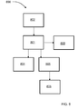
- a master 801 is here connected to a first slave 802 that is in the form of a communications terminal 802 as described for the examples above.
- the master 801 is here connected to a second slave 803 that is in the form of a lamp arrangement, a third slave 804 that is in the form of a sound signal device and a fourth slave 805 that is in the form of a motor relay arrangement that is adapted to control an electrical motor 806.
- the communications terminal 802 is here adapted to send a signal to the master 801, the signal corresponding to a certain state that indicates that a another slave should perform a certain action.
- the second slave 803, the third slave 804 and the fourth slave 805 are in this context constituted by output means or output devices.
- the master 801 instructs the motor relay arrangement 805 to start the electrical motor 806.
- the present invention is not limited to the examples above, but may vary freely within the scope of the appended claims.
- all examples may be combined in any suitable manner, the communications terminal 802 described with reference to Fig. 8 according to some aspects being any suitable communications terminal previously discussed, or any other suitable type of communications terminal that is adapted for the present invention.
- Any other types of electrical switches with associated switch operator devices are of course conceivable, such as for example touch buttons, slide buttons or remote control buttons.
- Many other output means or output devices are conceivable as well, such as for example radio transmitters.
- the inputs and the ouputs may handle any kind of digital information comprising at least a 4-bit word.
- the daughter card is constituted by a a first printed circuit board
- the main card is constituted by a a second printed circuit board. These may in turn comprise two or more sub-circuit boards.
- All switch parts may alse be referred to as contact parts, for example a switch operator device may also be referred to as a contact operator device, and an electrical switch may also be referred to as an electrical contact.
- the unit module is generally constituted by a manually actuatable integrated unit module.
- a manually actuatable integrated unit module 500, 520, 600 comprising:
- At least one communication terminal 620 is mounted on a second printed circuit board 502, 602 that is arranged for handling any first printed circuit board 501, 601, said second printed circuit board 502, 602 having inputs 621 for receiving signals 625a from said at least first electrical switch 503a, 603a on said first printed circuit board 501, 601, and also having outputs 622 for transmitting signals from the communications terminal 620 to output means 609 on said first printed circuit board 501, 601, where the inputs 621 are arranged to handle at least a 4-bit word, and where the outputs 622 are arranged to handle at least a 4-bit word, wherein said change of mode of said at least first electrical switch 503a, 603a, activating said at least one communication terminal 620 in such a way that said control signal 661 on said common communications link 512, 612 is produced, is adapted to control said associated output device 803, 804, 805.
- said at least one communication terminal 620 is at least one Actuator Sensor Interface module 620 being a slave module.
- said at least one slave module 620 is connected to said output device 406, 660, wherein said output device 406, 660 is a master module 401 in a control system, such as a Programmable Logic Controller or a Microcomputer, controlling in a pre-determined and cyclic way said at least one slave module 620.
- a control system such as a Programmable Logic Controller or a Microcomputer
- said common communications link 512, 612, 661 is an Actuator Sensor Interface bus.
- said change of mode is a change of level of a signal, and said level is activating said communication terminal 512, 612.
- said signal is an electrical voltage signal.
- means for receiving 621 receives no signal in said first position and receives any level or said signal in said second position.
- said switch operator device 504-506, 650 includes a manually operable actuator such as e.g. a button with a digital display 720, a manually operable selector switch 730, a manually operable key switch 103, or a manually operable pushbutton 101.
- a manually operable actuator such as e.g. a button with a digital display 720, a manually operable selector switch 730, a manually operable key switch 103, or a manually operable pushbutton 101.
- said manually operable actuator 101-104, 201-203, 301, 650, 720, 730 includes a pilot light 509, 609, having a light being determined by said associated output device 406, 660.
- said switch operator device 504-506, 650 comprises mechanical means 504-507 for moving between said first and second position; said mechanical means 504-507, having a slot 505, blocking light in said first position and passing light through said slot in said second position, where a change of the level of said electrical signal is produced in said at least first electrical switch 503a, 603a when said light is passing through said slot 505.
- a light pipe 508, which is mounted on the first printed circuit board 501, 601 has Light-Emitting Diodes 509, 609 that have at least two colours being mixed together in an additive RGB colour model added together in various ways reproducing a broad array of colours holding information.
- the manually actuatable integrated unit module 600, 700 has a housing 703; where said switch operator device 504-506, 650 is partially enclosed within said housing 703, and the first printed circuit board 501, 601 and the second printed circuit board 502, 602 are mounted within said housing 703.
- said switch operator device 504-506, 650 is connected to a manually operable actuator 720, 730 that comprises an indicator 721, 731.
- the manually actuatable integrated unit module 700 comprises a a manually operable actuator in the form of a rotatable switch knob 701 which can be turned in fixed steps, an encoder plate 704, adapted to be mechanically movable with the rotable switch knob 701, and a partially enclosing encoder device 707, where the encoder device 707 is arranged to interpret the positon of the encoded plate 704 and thus the setting of the switch knob 701 when the switch knob 701 is turned.
- the present disclosure also relates to a method of making a manually actuatable integrated unit module 500, 520, 600, wherein a unit module is formed including:
- the method comprises the steps:
Landscapes
- Engineering & Computer Science (AREA)
- Automation & Control Theory (AREA)
- Power Engineering (AREA)
- Microelectronics & Electronic Packaging (AREA)
- Physics & Mathematics (AREA)
- General Physics & Mathematics (AREA)
- Programmable Controllers (AREA)
Applications Claiming Priority (1)
| Application Number | Priority Date | Filing Date | Title |
|---|---|---|---|
| SE1550015A SE539937C2 (en) | 2015-01-09 | 2015-01-09 | Bus Powered Manually Actuable Contact and Communication Module |
Publications (2)
| Publication Number | Publication Date |
|---|---|
| EP3043221A1 true EP3043221A1 (fr) | 2016-07-13 |
| EP3043221B1 EP3043221B1 (fr) | 2018-02-28 |
Family
ID=55027427
Family Applications (1)
| Application Number | Title | Priority Date | Filing Date |
|---|---|---|---|
| EP15202019.4A Not-in-force EP3043221B1 (fr) | 2015-01-09 | 2015-12-22 | Module de contact et de communication pouvant être actionné manuellement et étant alimenté par un bus |
Country Status (2)
| Country | Link |
|---|---|
| EP (1) | EP3043221B1 (fr) |
| SE (1) | SE539937C2 (fr) |
Cited By (2)
| Publication number | Priority date | Publication date | Assignee | Title |
|---|---|---|---|---|
| CN109343454A (zh) * | 2018-11-05 | 2019-02-15 | 徐州路马力电控科技有限公司 | 一种基于行为检测的可编程控制器 |
| CN116107189A (zh) * | 2023-02-13 | 2023-05-12 | 宁波高新区新诚电子有限公司 | 一种定时装置及定时供电系统 |
Citations (3)
| Publication number | Priority date | Publication date | Assignee | Title |
|---|---|---|---|---|
| EP0740843A1 (fr) * | 1994-07-29 | 1996-11-06 | Square D Company | Module de commande integre a actionnement manuel et son procede de production |
| WO1997034310A1 (fr) * | 1996-03-19 | 1997-09-18 | Square D Company | Systeme integre de module de communication/contact/lampe temoin, alimente par un bus et actionnable manuellement |
| US20120182698A1 (en) * | 2009-09-29 | 2012-07-19 | Hans-Joachim Langels | Assembly for installing building systems engineering units |
-
2015
- 2015-01-09 SE SE1550015A patent/SE539937C2/en unknown
- 2015-12-22 EP EP15202019.4A patent/EP3043221B1/fr not_active Not-in-force
Patent Citations (3)
| Publication number | Priority date | Publication date | Assignee | Title |
|---|---|---|---|---|
| EP0740843A1 (fr) * | 1994-07-29 | 1996-11-06 | Square D Company | Module de commande integre a actionnement manuel et son procede de production |
| WO1997034310A1 (fr) * | 1996-03-19 | 1997-09-18 | Square D Company | Systeme integre de module de communication/contact/lampe temoin, alimente par un bus et actionnable manuellement |
| US20120182698A1 (en) * | 2009-09-29 | 2012-07-19 | Hans-Joachim Langels | Assembly for installing building systems engineering units |
Non-Patent Citations (1)
| Title |
|---|
| ANONYMOUS: "AS-Interface - Wikipedia, the free encyclopedia", 31 May 2016 (2016-05-31), pages 1 - 8, XP055276738, Retrieved from the Internet <URL:https://en.wikipedia.org/wiki/AS-Interface> [retrieved on 20160531] * |
Cited By (2)
| Publication number | Priority date | Publication date | Assignee | Title |
|---|---|---|---|---|
| CN109343454A (zh) * | 2018-11-05 | 2019-02-15 | 徐州路马力电控科技有限公司 | 一种基于行为检测的可编程控制器 |
| CN116107189A (zh) * | 2023-02-13 | 2023-05-12 | 宁波高新区新诚电子有限公司 | 一种定时装置及定时供电系统 |
Also Published As
| Publication number | Publication date |
|---|---|
| SE539937C2 (en) | 2018-01-30 |
| EP3043221B1 (fr) | 2018-02-28 |
| SE1550015A1 (sv) | 2016-07-10 |
Similar Documents
| Publication | Publication Date | Title |
|---|---|---|
| EP2434850B1 (fr) | Circuits d'entrée/sortie et dispositifs dotés de voyants de statut correspondant physiquement | |
| CN102594330B (zh) | 具有物理对应的状态指示器的输入/输出电路及装置 | |
| US5458048A (en) | Electro-pneumatic control device | |
| JP5253356B2 (ja) | 少なくとも2つの警告ランプを備えた警告灯装置 | |
| CN101606110B (zh) | 控制和/或数据传输模块 | |
| JP6093914B2 (ja) | 住宅オートメーションで使用するための一体化されたspdtまたはdpdtスイッチのspdtリレーとの組合せ | |
| EP3043221B1 (fr) | Module de contact et de communication pouvant être actionné manuellement et étant alimenté par un bus | |
| US9003095B2 (en) | Automation control component | |
| KR20170082713A (ko) | Plc기반 필드버스 실습장비 | |
| US20070173961A1 (en) | Automation controller with integrated hmi and modular i/o | |
| AU688947B2 (en) | Manually actuatable integrated control module and method of making same | |
| US20130086291A1 (en) | Switching logic module | |
| JPH11506265A (ja) | バス電源式の手動可能な統合された表示灯/接点/通信モジュール | |
| US11804980B2 (en) | Extension module for function extension of a network assembly | |
| CA3004128A1 (fr) | Module repartiteur a selecteur | |
| EP3905482B1 (fr) | Dispositif sans fil bidirectionnel | |
| EP2879153B1 (fr) | Dispositif et système de surcharge électronique intelligent modulaire configurable avec des outils de programmation intégrée | |
| EP3633639B1 (fr) | Colonne lumineuse pour indiquer un état d'un appareil à surveiller | |
| EP3076418A1 (fr) | Système de signalisation lumineuse pour dispositifs de contrôle et de commande électriques | |
| JP5081062B2 (ja) | 接点信号伝送システム | |
| JP2010093590A (ja) | コンセントシステム |
Legal Events
| Date | Code | Title | Description |
|---|---|---|---|
| PUAI | Public reference made under article 153(3) epc to a published international application that has entered the european phase |
Free format text: ORIGINAL CODE: 0009012 |
|
| AK | Designated contracting states |
Kind code of ref document: A1 Designated state(s): AL AT BE BG CH CY CZ DE DK EE ES FI FR GB GR HR HU IE IS IT LI LT LU LV MC MK MT NL NO PL PT RO RS SE SI SK SM TR |
|
| AX | Request for extension of the european patent |
Extension state: BA ME |
|
| 17P | Request for examination filed |
Effective date: 20161221 |
|
| RBV | Designated contracting states (corrected) |
Designated state(s): AL AT BE BG CH CY CZ DE DK EE ES FI FR GB GR HR HU IE IS IT LI LT LU LV MC MK MT NL NO PL PT RO RS SE SI SK SM TR |
|
| 17Q | First examination report despatched |
Effective date: 20170406 |
|
| GRAP | Despatch of communication of intention to grant a patent |
Free format text: ORIGINAL CODE: EPIDOSNIGR1 |
|
| RIC1 | Information provided on ipc code assigned before grant |
Ipc: H03K 17/968 20060101ALI20171027BHEP Ipc: G05B 19/05 20060101AFI20171027BHEP Ipc: H01H 9/16 20060101ALI20171027BHEP |
|
| INTG | Intention to grant announced |
Effective date: 20171114 |
|
| GRAS | Grant fee paid |
Free format text: ORIGINAL CODE: EPIDOSNIGR3 |
|
| GRAA | (expected) grant |
Free format text: ORIGINAL CODE: 0009210 |
|
| AK | Designated contracting states |
Kind code of ref document: B1 Designated state(s): AL AT BE BG CH CY CZ DE DK EE ES FI FR GB GR HR HU IE IS IT LI LT LU LV MC MK MT NL NO PL PT RO RS SE SI SK SM TR |
|
| REG | Reference to a national code |
Ref country code: GB Ref legal event code: FG4D Ref country code: CH Ref legal event code: EP |
|
| REG | Reference to a national code |
Ref country code: AT Ref legal event code: REF Ref document number: 974799 Country of ref document: AT Kind code of ref document: T Effective date: 20180315 |
|
| REG | Reference to a national code |
Ref country code: IE Ref legal event code: FG4D |
|
| REG | Reference to a national code |
Ref country code: DE Ref legal event code: R096 Ref document number: 602015008321 Country of ref document: DE |
|
| REG | Reference to a national code |
Ref country code: NL Ref legal event code: MP Effective date: 20180228 |
|
| REG | Reference to a national code |
Ref country code: LT Ref legal event code: MG4D |
|
| REG | Reference to a national code |
Ref country code: AT Ref legal event code: MK05 Ref document number: 974799 Country of ref document: AT Kind code of ref document: T Effective date: 20180228 |
|
| PG25 | Lapsed in a contracting state [announced via postgrant information from national office to epo] |
Ref country code: ES Free format text: LAPSE BECAUSE OF FAILURE TO SUBMIT A TRANSLATION OF THE DESCRIPTION OR TO PAY THE FEE WITHIN THE PRESCRIBED TIME-LIMIT Effective date: 20180228 Ref country code: HR Free format text: LAPSE BECAUSE OF FAILURE TO SUBMIT A TRANSLATION OF THE DESCRIPTION OR TO PAY THE FEE WITHIN THE PRESCRIBED TIME-LIMIT Effective date: 20180228 Ref country code: NO Free format text: LAPSE BECAUSE OF FAILURE TO SUBMIT A TRANSLATION OF THE DESCRIPTION OR TO PAY THE FEE WITHIN THE PRESCRIBED TIME-LIMIT Effective date: 20180528 Ref country code: FI Free format text: LAPSE BECAUSE OF FAILURE TO SUBMIT A TRANSLATION OF THE DESCRIPTION OR TO PAY THE FEE WITHIN THE PRESCRIBED TIME-LIMIT Effective date: 20180228 Ref country code: CY Free format text: LAPSE BECAUSE OF FAILURE TO SUBMIT A TRANSLATION OF THE DESCRIPTION OR TO PAY THE FEE WITHIN THE PRESCRIBED TIME-LIMIT Effective date: 20180228 Ref country code: LT Free format text: LAPSE BECAUSE OF FAILURE TO SUBMIT A TRANSLATION OF THE DESCRIPTION OR TO PAY THE FEE WITHIN THE PRESCRIBED TIME-LIMIT Effective date: 20180228 Ref country code: NL Free format text: LAPSE BECAUSE OF FAILURE TO SUBMIT A TRANSLATION OF THE DESCRIPTION OR TO PAY THE FEE WITHIN THE PRESCRIBED TIME-LIMIT Effective date: 20180228 |
|
| PG25 | Lapsed in a contracting state [announced via postgrant information from national office to epo] |
Ref country code: RS Free format text: LAPSE BECAUSE OF FAILURE TO SUBMIT A TRANSLATION OF THE DESCRIPTION OR TO PAY THE FEE WITHIN THE PRESCRIBED TIME-LIMIT Effective date: 20180228 Ref country code: LV Free format text: LAPSE BECAUSE OF FAILURE TO SUBMIT A TRANSLATION OF THE DESCRIPTION OR TO PAY THE FEE WITHIN THE PRESCRIBED TIME-LIMIT Effective date: 20180228 Ref country code: SE Free format text: LAPSE BECAUSE OF FAILURE TO SUBMIT A TRANSLATION OF THE DESCRIPTION OR TO PAY THE FEE WITHIN THE PRESCRIBED TIME-LIMIT Effective date: 20180228 Ref country code: GR Free format text: LAPSE BECAUSE OF FAILURE TO SUBMIT A TRANSLATION OF THE DESCRIPTION OR TO PAY THE FEE WITHIN THE PRESCRIBED TIME-LIMIT Effective date: 20180529 Ref country code: BG Free format text: LAPSE BECAUSE OF FAILURE TO SUBMIT A TRANSLATION OF THE DESCRIPTION OR TO PAY THE FEE WITHIN THE PRESCRIBED TIME-LIMIT Effective date: 20180528 Ref country code: AT Free format text: LAPSE BECAUSE OF FAILURE TO SUBMIT A TRANSLATION OF THE DESCRIPTION OR TO PAY THE FEE WITHIN THE PRESCRIBED TIME-LIMIT Effective date: 20180228 |
|
| PG25 | Lapsed in a contracting state [announced via postgrant information from national office to epo] |
Ref country code: AL Free format text: LAPSE BECAUSE OF FAILURE TO SUBMIT A TRANSLATION OF THE DESCRIPTION OR TO PAY THE FEE WITHIN THE PRESCRIBED TIME-LIMIT Effective date: 20180228 Ref country code: RO Free format text: LAPSE BECAUSE OF FAILURE TO SUBMIT A TRANSLATION OF THE DESCRIPTION OR TO PAY THE FEE WITHIN THE PRESCRIBED TIME-LIMIT Effective date: 20180228 Ref country code: EE Free format text: LAPSE BECAUSE OF FAILURE TO SUBMIT A TRANSLATION OF THE DESCRIPTION OR TO PAY THE FEE WITHIN THE PRESCRIBED TIME-LIMIT Effective date: 20180228 Ref country code: IT Free format text: LAPSE BECAUSE OF FAILURE TO SUBMIT A TRANSLATION OF THE DESCRIPTION OR TO PAY THE FEE WITHIN THE PRESCRIBED TIME-LIMIT Effective date: 20180228 Ref country code: PL Free format text: LAPSE BECAUSE OF FAILURE TO SUBMIT A TRANSLATION OF THE DESCRIPTION OR TO PAY THE FEE WITHIN THE PRESCRIBED TIME-LIMIT Effective date: 20180228 |
|
| REG | Reference to a national code |
Ref country code: DE Ref legal event code: R097 Ref document number: 602015008321 Country of ref document: DE |
|
| PG25 | Lapsed in a contracting state [announced via postgrant information from national office to epo] |
Ref country code: DK Free format text: LAPSE BECAUSE OF FAILURE TO SUBMIT A TRANSLATION OF THE DESCRIPTION OR TO PAY THE FEE WITHIN THE PRESCRIBED TIME-LIMIT Effective date: 20180228 Ref country code: SK Free format text: LAPSE BECAUSE OF FAILURE TO SUBMIT A TRANSLATION OF THE DESCRIPTION OR TO PAY THE FEE WITHIN THE PRESCRIBED TIME-LIMIT Effective date: 20180228 Ref country code: CZ Free format text: LAPSE BECAUSE OF FAILURE TO SUBMIT A TRANSLATION OF THE DESCRIPTION OR TO PAY THE FEE WITHIN THE PRESCRIBED TIME-LIMIT Effective date: 20180228 Ref country code: SM Free format text: LAPSE BECAUSE OF FAILURE TO SUBMIT A TRANSLATION OF THE DESCRIPTION OR TO PAY THE FEE WITHIN THE PRESCRIBED TIME-LIMIT Effective date: 20180228 |
|
| PLBE | No opposition filed within time limit |
Free format text: ORIGINAL CODE: 0009261 |
|
| STAA | Information on the status of an ep patent application or granted ep patent |
Free format text: STATUS: NO OPPOSITION FILED WITHIN TIME LIMIT |
|
| 26N | No opposition filed |
Effective date: 20181129 |
|
| PG25 | Lapsed in a contracting state [announced via postgrant information from national office to epo] |
Ref country code: SI Free format text: LAPSE BECAUSE OF FAILURE TO SUBMIT A TRANSLATION OF THE DESCRIPTION OR TO PAY THE FEE WITHIN THE PRESCRIBED TIME-LIMIT Effective date: 20180228 |
|
| REG | Reference to a national code |
Ref country code: CH Ref legal event code: PL |
|
| PG25 | Lapsed in a contracting state [announced via postgrant information from national office to epo] |
Ref country code: MC Free format text: LAPSE BECAUSE OF FAILURE TO SUBMIT A TRANSLATION OF THE DESCRIPTION OR TO PAY THE FEE WITHIN THE PRESCRIBED TIME-LIMIT Effective date: 20180228 Ref country code: LU Free format text: LAPSE BECAUSE OF NON-PAYMENT OF DUE FEES Effective date: 20181222 |
|
| REG | Reference to a national code |
Ref country code: IE Ref legal event code: MM4A |
|
| REG | Reference to a national code |
Ref country code: BE Ref legal event code: MM Effective date: 20181231 |
|
| PG25 | Lapsed in a contracting state [announced via postgrant information from national office to epo] |
Ref country code: IE Free format text: LAPSE BECAUSE OF NON-PAYMENT OF DUE FEES Effective date: 20181222 Ref country code: FR Free format text: LAPSE BECAUSE OF NON-PAYMENT OF DUE FEES Effective date: 20181231 |
|
| PG25 | Lapsed in a contracting state [announced via postgrant information from national office to epo] |
Ref country code: BE Free format text: LAPSE BECAUSE OF NON-PAYMENT OF DUE FEES Effective date: 20181231 |
|
| PG25 | Lapsed in a contracting state [announced via postgrant information from national office to epo] |
Ref country code: LI Free format text: LAPSE BECAUSE OF NON-PAYMENT OF DUE FEES Effective date: 20181231 Ref country code: CH Free format text: LAPSE BECAUSE OF NON-PAYMENT OF DUE FEES Effective date: 20181231 |
|
| PG25 | Lapsed in a contracting state [announced via postgrant information from national office to epo] |
Ref country code: MT Free format text: LAPSE BECAUSE OF NON-PAYMENT OF DUE FEES Effective date: 20181222 |
|
| PG25 | Lapsed in a contracting state [announced via postgrant information from national office to epo] |
Ref country code: TR Free format text: LAPSE BECAUSE OF FAILURE TO SUBMIT A TRANSLATION OF THE DESCRIPTION OR TO PAY THE FEE WITHIN THE PRESCRIBED TIME-LIMIT Effective date: 20180228 |
|
| PG25 | Lapsed in a contracting state [announced via postgrant information from national office to epo] |
Ref country code: PT Free format text: LAPSE BECAUSE OF FAILURE TO SUBMIT A TRANSLATION OF THE DESCRIPTION OR TO PAY THE FEE WITHIN THE PRESCRIBED TIME-LIMIT Effective date: 20180228 |
|
| PG25 | Lapsed in a contracting state [announced via postgrant information from national office to epo] |
Ref country code: HU Free format text: LAPSE BECAUSE OF FAILURE TO SUBMIT A TRANSLATION OF THE DESCRIPTION OR TO PAY THE FEE WITHIN THE PRESCRIBED TIME-LIMIT; INVALID AB INITIO Effective date: 20151222 Ref country code: MK Free format text: LAPSE BECAUSE OF NON-PAYMENT OF DUE FEES Effective date: 20180228 |
|
| PG25 | Lapsed in a contracting state [announced via postgrant information from national office to epo] |
Ref country code: IS Free format text: LAPSE BECAUSE OF FAILURE TO SUBMIT A TRANSLATION OF THE DESCRIPTION OR TO PAY THE FEE WITHIN THE PRESCRIBED TIME-LIMIT Effective date: 20180628 |
|
| GBPC | Gb: european patent ceased through non-payment of renewal fee |
Effective date: 20191222 |
|
| PG25 | Lapsed in a contracting state [announced via postgrant information from national office to epo] |
Ref country code: GB Free format text: LAPSE BECAUSE OF NON-PAYMENT OF DUE FEES Effective date: 20191222 |
|
| PGFP | Annual fee paid to national office [announced via postgrant information from national office to epo] |
Ref country code: DE Payment date: 20221109 Year of fee payment: 8 |
|
| P01 | Opt-out of the competence of the unified patent court (upc) registered |
Effective date: 20230426 |
|
| REG | Reference to a national code |
Ref country code: DE Ref legal event code: R119 Ref document number: 602015008321 Country of ref document: DE |
|
| PG25 | Lapsed in a contracting state [announced via postgrant information from national office to epo] |
Ref country code: DE Free format text: LAPSE BECAUSE OF NON-PAYMENT OF DUE FEES Effective date: 20240702 |
|
| PG25 | Lapsed in a contracting state [announced via postgrant information from national office to epo] |
Ref country code: DE Free format text: LAPSE BECAUSE OF NON-PAYMENT OF DUE FEES Effective date: 20240702 |