EP3043370A1 - Dispositif d'extraction des particules chargées d'un espace de production et procédé d'utilisation d'un tel dispositif - Google Patents
Dispositif d'extraction des particules chargées d'un espace de production et procédé d'utilisation d'un tel dispositif Download PDFInfo
- Publication number
- EP3043370A1 EP3043370A1 EP15150613.6A EP15150613A EP3043370A1 EP 3043370 A1 EP3043370 A1 EP 3043370A1 EP 15150613 A EP15150613 A EP 15150613A EP 3043370 A1 EP3043370 A1 EP 3043370A1
- Authority
- EP
- European Patent Office
- Prior art keywords
- grid electrode
- layer
- electrode
- grid
- region
- Prior art date
- Legal status (The legal status is an assumption and is not a legal conclusion. Google has not performed a legal analysis and makes no representation as to the accuracy of the status listed.)
- Withdrawn
Links
Images


Classifications
-
- H—ELECTRICITY
- H01—ELECTRIC ELEMENTS
- H01J—ELECTRIC DISCHARGE TUBES OR DISCHARGE LAMPS
- H01J37/00—Discharge tubes with provision for introducing objects or material to be exposed to the discharge, e.g. for the purpose of examination or processing thereof
- H01J37/02—Details
- H01J37/04—Arrangements of electrodes and associated parts for generating or controlling the discharge, e.g. electron-optical arrangement or ion-optical arrangement
- H01J37/08—Ion sources; Ion guns
-
- H—ELECTRICITY
- H01—ELECTRIC ELEMENTS
- H01J—ELECTRIC DISCHARGE TUBES OR DISCHARGE LAMPS
- H01J27/00—Ion beam tubes
- H01J27/02—Ion sources; Ion guns
- H01J27/022—Details
- H01J27/024—Extraction optics, e.g. grids
-
- H—ELECTRICITY
- H01—ELECTRIC ELEMENTS
- H01J—ELECTRIC DISCHARGE TUBES OR DISCHARGE LAMPS
- H01J2237/00—Discharge tubes exposing object to beam, e.g. for analysis treatment, etching, imaging
- H01J2237/06—Sources
- H01J2237/065—Source emittance characteristics
- H01J2237/0653—Intensity
-
- H—ELECTRICITY
- H01—ELECTRIC ELEMENTS
- H01J—ELECTRIC DISCHARGE TUBES OR DISCHARGE LAMPS
- H01J2237/00—Discharge tubes exposing object to beam, e.g. for analysis treatment, etching, imaging
- H01J2237/06—Sources
- H01J2237/065—Source emittance characteristics
- H01J2237/0656—Density
-
- H—ELECTRICITY
- H01—ELECTRIC ELEMENTS
- H01J—ELECTRIC DISCHARGE TUBES OR DISCHARGE LAMPS
- H01J2237/00—Discharge tubes exposing object to beam, e.g. for analysis treatment, etching, imaging
- H01J2237/06—Sources
- H01J2237/083—Beam forming
Definitions
- the invention relates to a device for the extraction of electrical charge carriers from a charge carrier generation space, which allows a change in the shape of the total particle beam extracted by means of the device, and a method for operating such a device. Moreover, the invention relates to a method of processing the surface of a substrate using one or more total particle beams generated by at least one such device.
- Directed particle beams from electrical charge carriers are generated in a particle beam source by the extraction of electrical charge carriers, ie ions or electrons, from a charge carrier generation space, for example a plasma, whereby the particles are directed and jet-shaped after leaving the particle beam source move in space in a particle exit direction.
- a particle beam source by the extraction of electrical charge carriers, ie ions or electrons, from a charge carrier generation space, for example a plasma, whereby the particles are directed and jet-shaped after leaving the particle beam source move in space in a particle exit direction.
- a charge carrier generation space for example a plasma
- a grating electrode is understood to be a mechanical (physical or material) composite of a plurality, ie of at least two, of openings through which the charge carriers can pass.
- a grid electrode is a (generally) sheet-like component whose lateral dimensions are many times greater than its thickness, ie its extension in the particle exit direction, and which has a plurality of openings extending in the thickness direction over the entire thickness of the Extend component and allow passage of charge carriers through the component. At least in some areas, the grid electrode has an electrically conductive material that can be acted on by a potential so that the charge carriers can be extracted and accelerated or the partial beam or beams can be blocked.
- the electrically conductive grid electrode regions may be physically and electrically conductively connected to each other. This is the case, for example, with a grid electrode formed entirely from an electrically conductive material. However, the individual electrically conductive grid electrode regions may also be electrically insulated from one another, for example by an electrically insulating material arranged therebetween.
- a plurality of grid electrodes in the particle exit direction can be successively arranged in spaced-apart layers, wherein the openings of the individual grid electrodes correspond to each other, so that with a corresponding potential application of the individual grid electrodes or grid electrode areas charge carriers can pass as particle partial beams through the openings of the grid electrodes.
- At least three grid electrodes are used, which are referred to as a plasma, screen or beam grid electrode, as an acceleration or accelerating grid electrode and as a ground grid electrode according to their function.
- other electrodes can also be arranged in the device for the extraction of electrical charge carriers in order, for example, to influence the generated total particle beam with respect to its exit direction.
- Particle beams are used, for example, in ion beam or electron beam machining systems, inter alia for processing surfaces of a substrate.
- the topography of the surface or other physical or chemical properties of the surface can be changed by the impact of the particles on the surface.
- Both the achievable resolution, ie the minimum machined surface, and the quality of the processing depend strongly on the beam width of the total beam used. In general, better results are achieved with a small beam width. For example, small differences in thickness within a layer located on the surface of the substrate can be more accurately leveled with a total beam having a small beam width than with an overall beam having a large beam width. However, this is offset by a longer processing time of a substrate with a given area.
- each grid opening of a grid electrode can be separately applied to a potential so that the corresponding partial ion beam is transmitted or blocked.
- a disadvantage of these devices is that electrical lines from the interior of a grid electrode must be led to the outside to a power supply. Given the potential differences of up to 1500 V between the various grid electrodes or grid electrode areas and temperatures of up to 300 ° C, to which the grid electrodes are exposed during the operation of the particle beam source, this type of potential application poses a great challenge.
- the openings serve for the passage of the charge carriers through the respective grid electrode in the particle exit direction and have lateral expansions and a predetermined circumferential geometry, for example a round, elliptical, angular or irregular circumferential geometry.
- the lateral expansions and / or the circumferential geometries of mutually corresponding openings in the first and the second grid electrode may differ slightly from each other.
- At least the at least one first grid electrode region of the first grid electrode is formed in a first layer, while the at least one first grid electrode region of the second grid electrode is formed in a second layer.
- the first layer and the second layer each describe an area within the electrode array, i. in the space of the device for the extraction of electrical charge carriers, in which the at least two grid electrodes are arranged, wherein the first layer and the second layer are arranged successively in the particle exit direction and are always spaced from each other by a first distance along the particle exit direction.
- the first layer and the second layer can describe flat or uniformly or non-uniformly curved surfaces which can have any desired circumferential geometries in a projection of the layer in the particle exit direction. For example.
- the layers may be designed in such a way that the individual partial beams passing through the openings in the grid electrodes are focused, aligned or defocused parallel to one another.
- the arrangement of the second layer in front of or behind the first layer along the particle exit direction is possible.
- the at least one first grid electrode region of the first grid electrode forms a first electrically conductive layer portion of the first layer.
- a second electrically conductive layer portion is formed in the first layer, which is formed by at least one second electrically conductive grid electrode region of the first grid electrode or the second grid electrode.
- the first layer portion and the second layer portion are electrically insulated from each other and each extend over the entire thickness of the first layer, i. over the entire extent of the position in the particle exit direction.
- the second layer portion is electrically conductively connected to the at least one first grid electrode area of the second grid electrode.
- first layer portion of the second layer portion is electrically isolated, they can be acted upon with different or equal potentials.
- This loading is carried out for the second layer portion according to the invention via the at least one first Grid electrode region of the second grid electrode. This eliminates one of the first layer portion electrically insulated potential supply of the second layer portion within the first layer.
- the device according to the invention for the extraction of charge carriers thus represents an electrically switchable extraction grid electrode arrangement with the aid of which the beam characteristic of a particle beam can be changed.
- first grid electrode regions of the first grid electrode and the second grid electrode are preferably disposed within the respective grid electrode so as to adjoin the outer lateral periphery of the respective grid electrode, a second layer portion spaced from the outer lateral periphery of the first grid electrode becomes possible having the first layer portion different electrical potential.
- first layer portion different electrical potential.
- the first grid electrode comprises only the at least one first grid electrode area, while the second grid electrode has at least one second grid electrode area, which forms the second layer portion of the first layer.
- the first grid electrode is formed such that it does not completely image the first layer, but has at least one recess. This recess may adjoin the lateral periphery of the first grid electrode, i. be formed on the edge of the first grid electrode, or be spaced therefrom, i. be formed inside the first grid electrode.
- the at least one second grid electrode region of the second grid electrode is arranged in the recess and thus at least partially in the first layer.
- the at least one second grid electrode region of the second grid electrode is physically and electrically conductively connected to the at least one first grid electrode region of the second grid electrode and is preferably formed integrally therewith.
- the at least one second grid electrode area of the second grid electrode is formed so thick that a first surface of the at least one second grid electrode area of the second grid electrode is in the first position and a second surface of the at least one second grid electrode area of the second grid electrode is opposite to the first surface , located in the second location.
- the second grid electrode in the at least one second grid electrode area is substantially thicker than the at least one first grid electrode area of the second grid electrode Grid electrode. The second grid electrode thus "projects" into the first layer or into the first grid electrode.
- the at least one second grid electrode region of the second grid electrode has the same thickness as the at least one first grid electrode region of the second grid electrode.
- the second grid electrode has the same thickness at least in the first and second grid electrode areas and is shaped such that the at least one second grid electrode area is arranged in the first position.
- the second grid electrode may have a greater or smaller thickness. This means that the second grid electrode is "pushed in" into the first layer or into the first grid electrode.
- the second grid electrode of the first two embodiments of the first embodiment is configured such that the transitions between the at least one first grid electrode area of the second grid electrode and the at least one second grid electrode area of the second grid electrode are continuous on both surfaces of the second grid electrode.
- the transitions can, for example, be rounded off and / or obliquely executed.
- the at least one first grid electrode area of the second grid electrode completely covers the second layer, while the at least one second grid electrode area of the second grid electrode at least in some lateral sections of the second grid electrode area is spaced from the at least one first grid electrode area of the second grid electrode is.
- the second grid electrode does not form a closed structure, but consists of two sections which are connected to one another in an electrically conductive manner in some lateral sections of the at least one second grid electrode area.
- the at least one second grid electrode region of the second grid electrode is formed as a physically independent grid electrode, but electrically conductively, for example. Via electrically conductive spacers, with the at least one first grid electrode region of the second grid electrode, which completely images the second layer is connected.
- the first grid electrode further comprises at least one second grid electrode area forming the second layer portion of the first layer.
- the first grid electrode is formed physically in one piece and completely covers the first layer, but the at least one first grid electrode area is electrically isolated from the at least one second grid electrode area.
- the second grid electrode has at least one first grid electrode area, which is formed in the second layer and is connected in an electrically conductive manner to the at least one second grid electrode area of the first grid electrode.
- the second grid electrode is formed physically in one piece and forms the second layer completely.
- the first grid electrode and the second grid electrode are formed such that they completely map the first layer or the second layer and are electrically conductively connected to one another in the region of the second layer part.
- an electrode arrangement which comprises a plurality of lateral areas, wherein different embodiments are formed in different areas.
- the openings for the charge carrier passage in at least one second grid electrode area of the first grid electrode or the second grid electrode are preferably equal to or different from the openings for the carrier passage in at least one first grid electrode area of the second grid electrode with respect to their lateral extent and / or their circumferential geometry.
- the second layer portion of the first layer may be formed by a continuous second grid electrode region of the first or the second grid electrode.
- the second layer portion of the first layer may also be formed by a plurality of spaced apart second grid electrode regions of the first or the second grid electrode.
- the second grid electrode regions may have identical or different circumferential geometries, ie shapes in the projection of the grid electrode region in the particle exit direction. For example. Round, elliptical, triangular, quadrangular or polygonal shapes or uneven shapes are possible.
- the second grid electrode regions may be uniform or non-uniform over the lateral Extension of the first layer to be distributed. For example. they may be arranged uniformly with respect to an axis of rotation or one or more lines of intersection of the first layer.
- the at least one electrode arrangement preferably has at least one further, electrically conductive grid electrode provided with corresponding openings.
- Each of these further grid electrodes comprises at least one first grid electrode area in a further layer.
- the further layer can be arranged in front of or behind the second layer along the particle exit direction in the electrode chamber, wherein the further layer and the layer adjacent to it, for example the second layer, are spaced from each other by a further distance along the particle exit direction.
- the further layer describes a surface which is congruent or similar to the first and the second layer.
- Another grid electrode is preferably a ground grid electrode. However, other grid electrodes may also be present as further grid electrodes.
- the at least one electrode arrangement comprises at least one further grid electrode, which is arranged adjacent to the second grid electrode on the side facing away from the first grid electrode side of the second grid electrode, and the second grid electrode is configured such that the at least one second grid electrode area of the second grid electrode has the same thickness
- this further grid electrode preferably also has at least one second grid electrode region which is arranged in the second layer and electrically conductively connected to the at least one first grid electrode region of the further grid electrode.
- the lateral arrangement of the at least one second grid electrode area of the further grid electrode within the second position corresponds to the lateral arrangement of the at least one second grid electrode area of the second grid electrode within the first position.
- further grid electrodes adjacent to this further grid electrode may have grid electrode areas arranged in different layers. In other words, even further grid electrodes can be "pushed in” into the respectively adjacent grid electrode or "project” into it.
- Said first and second grid electrode regions of the first grid electrode, the second grid electrode or a further grid electrode each have the described openings, which correspond to the openings in other grid electrodes.
- one or more or all of the grid electrodes of the electrode arrangement may each have further areas in which no openings are formed. These areas are, for example, edge areas which are used to hold the respective grid electrode in the Electrode arrangement and / or for electrical contacting of the grid electrode regions of the respective grid electrode which are electrically connected to this area serve.
- the device for the extraction of electrical charge carriers has a plurality of electrode arrangements for the extraction of charge carriers, wherein one or more of the electrode arrangements next to each other in a first direction along the lateral extent of the device for the extraction of electrical charge carriers and at most two electrode arrangements side by side in a second Direction along the lateral extent of the device for the extraction of electrical charge carriers are arranged so that the electrode assemblies cover almost the entire lateral extent of the device for the extraction of electrical charge carriers. Only edge regions of the device for the extraction of electrical charge carriers and / or regions between adjacent electrode arrangements may be excluded from this. Since the plurality of electrode arrangements are arranged at most in a nx 2 matrix, all electrode arrangements can be contacted externally for application to defined potentials.
- the lateral extent of the device for the extraction of electrical charge carriers is the extent of the device for the extraction of electrical charge carriers in the area in which the charge carriers can be extracted with the aid of the at least one electrode arrangement from a charge carrier generation space, for example a plasma. That is, the lateral extent is defined perpendicular to the particle exit direction.
- the plurality of electrode arrays may have the same or different patterns of the second layer portions.
- pattern is understood to mean both the one or more circumferential geometries of the at least one second grid electrode area and the lateral arrangement of the at least one second grid electrode area in a specific electrode arrangement.
- one or more or all of the grid electrodes contained in the electrode arrangement are individually detachably arranged from a holder of the electrode arrangement or from one of the other grid electrodes.
- individual grid electrodes which, for example, have a higher level of wear due to thermal, mechanical or electrical stress, can be individually removed from the electrode arrangement and replaced or replaced by new grid electrodes. If the first and the second grid electrode are exchanged and replaced by corresponding grid electrodes having a different pattern, a new device for the extraction of electrical charge carriers can be provided be created, which allows a new, different beam characteristics of the producible particle beam.
- the at least one electrode arrangement in the particle exit direction successively comprises a plasma grid electrode, a grid electrode and an accelerator grid electrode, wherein the grid electrode is the first grid electrode and the plasma grid electrode or the accelerator grid electrode is the second grid electrode.
- “successively” means only that the said grid electrodes are arranged in the named order. Between the switching grid electrode and the grid electrode, which is not the second grid electrode, further grid electrodes may be arranged.
- a method according to the invention for operating a device according to the invention for the extraction of electrical charge carriers with a plasma grid electrode, a grid electrode and an accelerator grid electrode wherein the grid electrode is the first grid electrode and the plasma grid electrode or the accelerator grid electrode is the second grid electrode, depending on a desired beam characteristic of each of the at least one electrode arrangement is driven by means of a particle beam passing through the at least one electrode arrangement such that the at least one first grid electrode area of the switching grid electrode of the specific electrode arrangement has a first potential and the acceleration grid electrode of the specific one Electrode arrangement with a second potential beaufsch be lagt.
- the values of the first and of the second potential are selected in the individual switching states of the device for the extraction of electrical charge carriers in such a way that they permit a passage of the charge carriers through the corresponding grid electrode areas or block the corresponding grid electrode areas for the charge carrier passage, and always relate to the latter Potential value of the plasma grid electrode or the charge carrier generation space.
- the values of the first and of the second potential for a charge carrier passage are always more negative for positive charge carriers than the potential of the plasma grid electrode and more positive for negative charge carriers than this.
- the values of the first and the second potential for blocking the charge carrier passage are positive values for positive charge carriers higher than the potential of the plasma grid electrode or the charge carrier generation space, while for negative charge carriers, these are higher negative values.
- the individual concrete potential values for the switching grid electrode and the acceleration grid electrode are thus dependent from the charge carrier type and polarity as well as the concrete embodiment of the device for the extraction of electric charge carriers and the charge carrier generation space.
- the first potential has a first value U 11 and the second potential has a second value U 21 , both of which are suitable for allowing the passage of charge carriers through the corresponding grid electrode regions.
- the first value U 11 and the second value U 21 may be the same or nearly the same, or substantially different, as long as the charge carrier passage is ensured.
- the first potential has a third value U 12 , which prevents a charge carrier passage through the grid electrode regions of the grid electrode and the acceleration grid electrode corresponding to the first layer portion, and the second potential a fourth value U 22 , which allows the passage of charge carriers through the allows the second layer portion corresponding grid electrode areas in the switching grid electrode and the accelerating grid electrode, on.
- U 12 the third value
- U 22 the fourth value
- the first potential has a fifth value U 13 and the second potential has a sixth value U 23 , both of which prevent the charge carrier passage through the corresponding grid electrode regions.
- the fifth value U 13 and the sixth value U 23 may be the same, almost the same or different. This prevents the extraction of charge carriers over the entire lateral extent of the electrode arrangement and generates no particle beam.
- the third value U 12 and the fifth value U 13 are adapted to the respective configuration of the electrode arrangement and the respective switching state.
- the third value U 12 and the fifth value U 13 both of which prevent the carrier passage through the at least one first grid electrode region of the grid electrode, may be the same, nearly the same or different.
- the first potential and / or the second potential are applied pulsed.
- the pulse lengths and / or the pulse ratios of the respective potentials may be the same or different from one another. Also possible is a temporal variation of the pulse length and / or the pulse ratio of the respective potentials.
- the plasma grid electrode is subjected to a third potential U beam whose polarity depends on the charge carriers to be extracted.
- the plasma grid electrode is not subjected to a defined potential, so that the potential of the plasma grid electrode is floated and essentially determined by the potential of an additional plasma electrode in the charge carrier generation space.
- the electrode arrangement in the particle exit direction downstream of the acceleration grid electrode has an electrically conductive and correspondingly apertured ground grid electrode comprising at least a first grid electrode area in a third layer, the second layer and the third layer being spaced from each other by a second distance along the particle exit direction, then
- the ground grid electrode is preferably grounded.
- the device for extracting electrical charge carriers comprises a plurality of such electrode arrangements, then each of the several electrode arrangements is driven as described above, so that the at least one particle beam emerging from the entire device for the extraction of electrical charge carriers has a desired beam characteristic.
- one or more of the above-described inventive device for the extraction of electrical charge carriers for processing the surface of a substrate using one or more particle beams from at least one device for the extraction of electrical charge carriers are used such that during the processing of the substrate in dependence on a known Property pattern of the substrate surface and the process progress, the beam characteristic of one or more particle beams from the at least one device for the extraction of electrical charge carriers by means of the inventive method for operating the device for the extraction of electrical charge carriers is changed as desired.
- a property pattern of the substrate surface is understood to mean the physical and / or chemical properties related to defined surface areas of the substrate surface, as well as the surface topography, which have a distribution over the entire substrate surface caused by the production or previous processing of the substrate.
- the substrate surface is affected by the impact of the influenced by electrical charge carriers.
- material can be removed from or applied to the substrate surface or the chemical or physical properties of the material of the substrate surface are changed so that a reaction with other substances is enabled or prevented. It is also possible to influence hygroscopic, optical, crystallographic, electrical, magnetic or other physical properties.
- ions are used to process the surface of a substrate, so that the device for the extraction of electrical charge carriers is an ion beam source.
- one or more electric charge extraction devices are controlled so that a plurality of particle beams impinge simultaneously on the substrate, the plurality of particle beams having the same or different beam characteristics.
- one or more electric charge extraction devices are controlled so that a plurality of particle beams strike a common area on the substrate surface, the plurality of particle beams having different beam characteristics, and wherein the common area is approximately the incident surface of the incident particle beam having the largest impact area has all the incident particle beams corresponds.
- the formation of structures with different heights or depths within a structure and / or with different or non-uniform shapes in only one processing operation is possible.
- the beam characteristics with respect to the lateral extent or the pattern of the respective particle beam and / or with respect to the focus, the particle density, the particle type or other characteristics may differ.
- Fig. 1 schematically shows a device (1) for the extraction of electrical charge carriers from a charge carrier generation space (2).
- This charge carrier generation space (2) is, for example, a plasma that has been generated within a housing (31) of a particle beam source (3) with the aid of one or more electrodes (4).
- electrodeless plasma generating devices such as, for example, inductively coupled plasma sources or microwave-based sources using the ECR effect, are used. Hot filament sources can also be used.
- the plasma chamber ie the space in which the plasma is generated, can be designed, for example, in the shape of a pot or trough or otherwise as known from the prior art.
- the charge carriers to be extracted can also be generated elsewhere, so that the charge carrier generation space (2) is not a plasma. For example.
- the specific embodiment of the charge carrier generation space (2) is freely selectable, as long as there is a sufficient supply of electrical charge carriers on the device (1) for the extraction of electrical charge carriers.
- the device (1) for the extraction of electrical charge carriers is in or at the particle beam source (3 ) and includes one or more electrode assemblies (1a, 1b).
- the one or more electrodes (4) for Generation of the charge carriers and the device (1) for extracting the charge carriers by means of a device (5) for generating one or more electrical voltages via a switching device (6) and corresponding electrical lines (7) acted upon by potentials.
- the electrode arrangements (1a, 1b) generally consist of one or more grid electrodes.
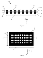
- Fig. 2A shows a prior art electrode assembly (1a ') in cross-section, while Fig. 2B shows a grid electrode in plan view.
- the line AA in Fig. 2B marks the section line of the representation of Fig. 2A .
- the prior art electrode assembly (1a ') comprises a plasma grid electrode (11'), a gridded grid electrode (12 '), an accelerator grid electrode (13') and a ground grid electrode (14 ').
- Each of these grid electrodes consists of an electrically conductive grid electrode material (15) and has openings (16) through which the extracted electrical charge carriers, hereinafter called particles for short, can pass in the z-direction.
- the z-direction is thus the particle exit direction. That is, the openings (16) extend from one surface of the grid electrode to the opposite surface of the grid electrode, wherein the opening may be straight or oblique. Metals, for example molybdenum or tungsten, or graphites are used as the grid electrode material, wherein the grid electrode material may also be a layer sequence of a plurality of electrically conductive materials or also of an electrically non-conductive base body with a coating of an electrically conductive material.
- the openings (16) can have different peripheral geometries, for example they can be round, elliptical or polygonal, have different dimensions and / or be distributed uniformly or non-uniformly over the lateral extent of the grid electrode in the xy plane.
- the openings (16) have, for example, a hole diameter of 0.5 mm to 3 mm, while the grid electrode material (15) typically has a land width, ie a width between two adjacent openings (16) of 0.5 mm to 1 mm.
- the distribution of the openings (16) over the entire lateral extent of a grid electrode can be configured such that a homogeneous distribution of the current density in the particle beam or in selected areas of the particle beam is achieved.
- the achievable current density can be adjusted in a corresponding area of the particle beam.
- a high current density is achieved by a dense arrangement of openings (16), ie small web widths.
- Each grid electrode has a first lateral extent (10) in the x-direction, a second lateral extent (19) in the y-direction and a thickness (17) in the z-direction, wherein the first lateral extent (10) and the second lateral extent (19) may be from a few mm to a few meters and the thickness (17) may typically be 200 ⁇ m to 1 mm.
- the grid electrodes can have any desired peripheral geometry, which can be, for example, rectangular, round, elliptical or polygonal.
- all grid electrodes of an electrode arrangement have the same design or only slight differences in the parameters mentioned.
- the individual grid electrodes have a distance (18) from one another, which is typically between 0.5 mm and 1.5 mm and is preferably the same between all grid electrodes.
- the mentioned grid electrode parameters are chosen according to the mechanical, electrical and thermal loading of the grid electrodes.
- the grid electrodes are each formed in a layer which is either flat, as in the Fig. 2A shown, or has a radius of curvature, but the distance between the individual grid electrodes always remains approximately the same. It is characteristic that each grid electrode is formed only in one layer and each layer is completely electrically isolated from the other layers.
- an inventive electrode arrangement (1a), as shown in Fig. 3 is characterized by an electrically conductive connection between a grid electrode area forming a layer portion of a first layer and a grid electrode area formed in a second layer, the grid electrode area in the first layer being electrically insulated from other grid electrode areas in the first layer is.
- Fig. 3 shows a schematic representation of this arrangement. There are shown a first layer (100) and a second layer (200), which are symbolized by dashed lines and each form a closed surface. The first layer (100) and the second layer (200) are spaced apart by a first distance (300). In the first layer (100), a first grid electrode is arranged, which has first grid electrode areas (110a, 110b).
- These grid electrode regions (110a, 110b) form the first layer portion (101) of the first layer (100).
- a second grid electrode is arranged, which has first grid electrode areas (210a, 210b).
- a further grid electrode region is arranged which forms a second layer portion (102) of the first layer (100) and which is electrically insulated from the first layer portion (101) of the first layer (100). but electrically conductively connected to the first grid electrode regions (210a, 210b) of the second grid electrode in the second layer (200).
- This electrical connection is shown schematically by the lines with the reference numeral 301, wherein the electrical connection (301) no electrical line in the sense of a wire bridge o.ä. have to be.
- the second layer portion (102) may be spaced from the circumference of the first layer (100), ie, located within the first layer (100). Nevertheless, via the electrical connection (301) with the first grid electrode regions (210a, 210b) of the second grid electrode, which adjoin the circumference of the second layer (200), an impact of the second layer portion (102) with an electric potential, that of the electric Potential of the first layer portion (101) is different, via an electrical contact to the outer boundary, ie the circumference, the electrode assembly (1 a) possible.
- first grid electrode regions (210a, 210b) of the second grid electrode in addition to the first grid electrode regions (210a, 210b) of the second grid electrode, further grid electrode regions of the second grid electrode or grid electrode regions of a further grid electrode may be formed. It is also possible for the first grid electrode regions (210a, 210b) of the second grid electrode to extend continuously over the entire second layer (200). For a clear presentation of the basic idea according to the invention are in Fig. 3 only the first grid electrode regions (210a, 210b) of the second grid electrode have been shown while other regions in the second layer (200) have been omitted.
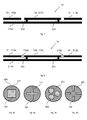
- the configuration of the electrical connection (301) and the first grid electrode and the second grid electrode will be explained below with reference to some embodiments, wherein the representation of the openings (16) in the individual grid electrodes is omitted for clarity. Also, only one grid electrode area forming the second layer portion is shown, and the number of these grid electrode areas is not limited.
- the first grid electrode has only the first grid electrode areas (110a, 110b) and thus does not cover the entire first layer (100), while the second layer section (102) of the first layer (100) is formed by a second grid electrode region (210c) of the second grid electrode.
- Fig. 4 shows a first embodiment of this embodiment, wherein the second grid electrode region (210c) is thicker than the first grid electrode regions (210a, 210b) of the second grid electrode.
- a first surface (211) of the second grid electrode region (210c) is formed in the first layer (100)
- a second surface (212) of the second grid electrode region (210c) is disposed in the second layer (200).
- the first surface (211) and the second surface (212) face each other.
- the second grid electrode "protrudes" into the first layer (100).
- the second grid electrode area (210c) is preferably integral with the first one Grid electrode regions (210a, 210b) of the second grid electrode formed and can be prepared, for example, by means of an additive (selective deposition) or a subtractive (etching) method.
- the geometry of the openings, for example the hole diameter, in the second grid electrode area (210c) is changed relative to that of the openings in the first grid electrode areas (210a, 210b) in order to compensate for the effects of the greater thickness of this area on the passing charge carriers.
- the openings in the second grid electrode area (210c) may also be arranged differently than in the first grid electrode areas (210a, 210b).
- Fig. 5 11 shows a second embodiment of the first embodiment in which the second grid electrode region 210c has the same thickness as the first grid electrode regions 210a, 210b of the second grid electrode and is formed integrally therewith.
- This embodiment can be produced, for example, by a forming process of the second grid electrode, such as swaging. Again, the geometry and / or arrangement of the openings in the second grid electrode area (210c) may differ from that in the first grid electrode areas (210a, 210b).
- the transitions between the first grid electrode areas (210a, 210b) and the second grid electrode area (210c) may be continuous. This is exemplary of the first embodiment in FIG Fig. 6 shown. In this case, the transition between the first surface (211) of the second grid electrode area (210c) to the surface of the first grid electrode areas (210a, 210b) in each case runs obliquely. Alternatively or additionally, the surfaces of the second grid electrode may be rounded at the transition points, so that a round "edge" is formed.
- Fig. 7 shows a further embodiment of the first embodiment, wherein the second grid electrode region (210c) of the second grid electrode is not formed integrally with the first grid electrode region (210a) of the second grid electrode.
- the first grid electrode region (210a) completely covers the second layer (200), while the second grid electrode region (210c) is spaced from the first grid electrode region (210a) of the second grid electrode by the first distance (300) and via at least one electrically conductive spacer (210). 302) is connected to the first grid electrode area (210a) of the second grid electrode.
- Such spacers (302) may be, for example, bumps, balls, cylinders, or the like, which include both the electrical connection and ensure the mechanical stability of the arrangement of the second grid electrode region (210c) in the first layer (100).
- the second grid electrode area (210c) of the second grid electrode has no physical (mechanical) connection to the first grid electrode areas (110a, 110b) of the first grid electrode except via the spacers (302).
- the second grid electrode region (210c) may be formed as a self-contained device, which is subsequently connected to the first grid electrode region (210a) by means of the spacers (302).
- the second grid electrode area (210c) common to the first grid electrode area (210a) of the second grid electrode or to the first grid electrode areas (110a, 110b) of the first grid electrode, and later to generate a physical / mechanical "separation" ,
- the first grid electrode has, in addition to the first grid electrode areas (110a, 110b), a second grid electrode area (110c) which is physically (mechanically) connected to the first grid electrode areas (110a, 110b) and the second grid electrode Layer portion (102) of the first layer (100) forms.
- the first grid electrode forms the entire first layer (100). This is in Fig. 8 shown.
- the second grid electrode region (110c) of the first grid electrode is electrically insulated from the first grid electrode regions (110a, 110b) by electrically insulating grid electrode regions (110d) and is electrically conductive with the first grid electrode region (210a) of the second grid electrode, completely covering the second layer (200) fills, connected via at least one electrically conductive connection (301).
- electrically conductive connections (301) can again be used with reference to Fig. 7 be described spacer, but in this embodiment does not have to ensure the mechanical stability of the arrangement, as this is already given by the electrically insulating grid electrode regions (110d) of the first grid electrode.
- the second layer portion (102) can be formed by a coherent grid electrode area. This is in the Figs. 9A and 9B which shows the first layer (100) with the first layer portion (101) and the second layer portion (102). The electrical insulation by a physical distance or an electrically insulating intermediate region between the two ply shares is not shown here.
- Figs. 9C and 9D show other embodiments in which the second layer portion (102) is formed by a plurality of spaced apart grid electrode regions.
- three round grid electrode areas form the second layer portion (102) while in Fig. 9D four rectangular grid electrode areas form the second layer portion (102).
- the grid electrode areas of the second layer portion (102) are each of which is uniformly formed with respect to its circumferential geometry and arranged uniformly within the first layer (100), for example, with respect to a center of the first layer (100).
- the individual grid electrode areas can also be designed differently with respect to their circumferential geometry and / or their arrangement within the first layer (100).
- the grid electrode regions which form the second layer portion (102) can also adjoin the circumference of the first layer (100).
- the circumferential geometry of the first layer (100) and the grid electrode regions forming the second layer portion (102) is not limited to the geometries shown. Also, another arrangement of the grid electrode regions forming the second layer portion (102) within the first layer (100) is possible.
- the peripheral geometries and dimensions of the grid electrode regions forming the second layer portion (102) and their arrangement within the first layer (100) represent a pattern of the electrode assembly (1a).
- the electrode arrangement may also have further grid electrodes, which are likewise electrically conductive and have corresponding openings.
- the electrode arrangement (1a) consists of four grid electrodes.
- these are the first grid electrode (110) which implements a grid element (12), the second grid electrode (210), which constitutes an acceleration grid electrode (13), and two further grid electrodes (401, 402), which serve as the plasma grid electrode (11 ) and ground grid electrode (14).
- the grid electrodes may also be arranged differently, in which case the functionalities of the grid electrodes are also different.
- the first grid electrode (110) is the grid electrode and the plasma grid electrode realizes the second grid electrode (210).
- the grid electrodes in the particle exit direction, ie away from the charge generation space are always arranged in the following order: plasma grid electrode (11), grid electrode (12), acceleration grid electrode (13), and ground grid electrode (14).
- further grid electrodes may, for example, be arranged between the plasma grid electrode (11) and the switch grid electrode (12) or between the acceleration grid electrode (13) and the ground grid electrode (14), but not between the grid electrodes which form the first grid electrode and the second grid electrode.
- the further grid electrodes (401, 402) each comprise at least one first grid electrode area, which is arranged in a further layer, wherein the further layer and the layer adjacent to it are spaced from each other by a further distance along the particle exit direction.
- the plasma grid electrode 11 is arranged in a third position, which is spaced apart from the first position by a second distance, wherein the plasma grid electrode 11 has only grid electrode regions in the third position in the illustrated case.
- the plasma grid electrode (11) is uniform and has no "bulges" or other irregularities that may, for example, affect a plasma unfavorable.
- the acceleration grid electrode (13), according to the second embodiment of the first embodiment of the electrode assembly (1a), as in Fig. 5 is shown, configured and thus “invaded” into the first layer, one (or more) of the further grid electrodes, which is arranged on the side facing away from the first grid electrode (110) side of the second grid electrode (210), second grid electrode regions which are arranged in the second layer.
- further grid electrodes can be inserted into the respective adjacent layer.
- the ground grid electrode (14) having first grid electrode areas (402a, 402b) and a second grid electrode area (402c).
- the first grid electrode regions (402a, 402b) are disposed in a fourth layer spaced at a third distance from the second layer, while the second grid electrode region (402c) is disposed in the second layer.
- the distances between regions with different potential for example between the acceleration grid electrode (13) and the ground grid electrode (14), over the entire extent of the respective grid electrodes across, so that a uniform particle beam is formed.
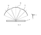
- Fig. 11 shows an example of an electrode assembly (1a) in which the individual layers are not flat, but curved surfaces, so that the individual, partially sub-beams (8) passing through the openings in the grid electrodes are focused so that they all in a common incident surface concentrated impact on a substrate (9).
- the electrode assembly (1a) again with reference to Fig. 10 described grid electrodes, wherein the first grid electrode (110) and the second grid electrode (210) as in the reference to the Fig. 5 described embodiment are formed.
- An adaptation of the peripheral geometries, the dimensions and / or the arrangement of the openings in the individual grid electrodes is advantageous in order to compensate for the configuration of the layers as curved surfaces, ie as surfaces with an impressed, finite radius.
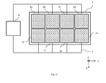
- FIG. 12 an embodiment of the inventive device (1) for the extraction of charge carriers with a plurality of electrode assemblies (1a - 1h) is shown in plan view.
- the electrode arrangements (1a-1h) are arranged in a 4x2 matrix, ie, two electrode arrangements (1a-1d or 1e-1h) are arranged in two rows.
- a first lateral extent of the device (1) ie along the x-direction
- four electrode arrangements (1a-1d or 1e-1h) are arranged side by side
- a second lateral extent of the device (1) ie along the y direction, only two electrode arrangements are arranged side by side.
- all the electrode assemblies (1a-1h) are electrically contactable from the outer periphery of the device (1), so that they are acted upon by the switching device (6) or a plurality of switching devices and the corresponding electrical lines (7) with one or more electrical potentials can.
- all the electrode assemblies (1a-1h) have the same pattern of the layer portions of the first layer, but one or more or all of the electrode arrangements may also have different patterns.
- the electrode arrangements (1a-1h) cover almost the entire lateral extent of the device (1), wherein only edge areas and intermediate areas between the individual electrode arrangements (1a-1h) are not covered.
- the inventive device (1) is operated, so that a desired beam characteristic of at least one electrode assembly (1a) passing through particle beam is generated.
- the wiring of an electrode arrangement is shown, which has a switching grid electrode (12), which acts as a first grid electrode (110), and an acceleration grid electrode (13), which acts as a second grid electrode (210), wherein the acceleration grid electrode (13) in Particle exit direction after the switch grid electrode (12) is arranged.
- the first grid electrode (110) and the second grid electrode (210) are, for example, as in FIG Fig. 4 illustrated first embodiment of the first embodiment.
- the first grid electrode (110) and the second grid electrode (210) are connected via a switching device (6) to an apparatus (5) for generating electrical voltages which have at least two different values for a first potential of the first grid electrode areas (110a, 110b).
- the first grid electrode (110) and at least two different values for a second potential of the first grid electrode areas (210a, 210b) of the second grid electrode (210) and of the second grid electrode area (210c) of the second grid electrode (210) which is electrically conductively connected thereto.
- the first potential has a first value U 11 and the second potential has a second value U 21 , the values being suitable for extracting charge carriers from the charge generation space. That is, the first value U 11 and the second value U 21 are smaller (more negative) for positive carriers than the value of the potential in the carrier generation space or the potential of a plasma grid electrode (hereinafter called U beam ), while it is reversed for negative carriers.
- the amount of the second value U 21 may, for example, deviate by a maximum of ⁇ 10% from the value of the first value U 11 .
- even larger differences are possible as long as the first and second potential allow the passage of charge carriers through all grid electrode areas.
- the entire lateral extent of the electrode assembly used for the extraction of charge carriers is both suitable for extracting carriers
- the entire lateral extent of the electrode assembly used for the extraction of charge carriers is both suitable for extracting carriers
- the entire lateral extent of the electrode assembly used for the extraction of charge carriers is both suitable for extracting carriers
- the entire lateral extent of the electrode assembly used for the extraction of charge carriers is both suitable for extracting carriers
- the entire lateral extent of the electrode assembly used for the extraction of charge carriers is both suitable for extracting carriers
- such an focused ion beam for an exemplary electrode arrangement having a grid electrode diameter of 40 mm can have an impact diameter on a substrate surface of about 4.5 mm to be processed.
- grating electrode diameter is understood to mean the diameter of a circular region of the electrode arrangement relative to a layer in which grating electrode regions are formed.
- the grid electrode areas have the openings described above, while the individual grid electrodes can also have edge areas, for example for physically fixing the grid electrode in a housing or another device or for applying a potential to the grid electrode, in which no openings are formed.
- edge areas for example for physically fixing the grid electrode in a housing or another device or for applying a potential to the grid electrode, in which no openings are formed.
- the first potential has a third value U 12
- the second potential has a fourth value U22.
- the third value U 12 is suitable for preventing or greatly restricting the extraction of charge carriers from the charge carrier generation space.
- the third value U 12 is larger (more positive) than the value of the potential in the carrier generation space or as U beam , while it is reversed for negative carriers.
- the fourth value U 22 is suitable for extracting charge carriers, wherein the fourth value U 22 may be equal to the second value U 21 , as shown in FIG Fig. 13B is shown.
- the fourth value U 22 may also be different from the second value U 21 in order to compensate for the changed electrical environmental conditions.
- the second grid electrode region (210c) of the second grid electrode (210) which forms the second layer portion of the first layer and is electrically conductively connected to the first grid electrode regions (210a, 210b) of the second grid electrode (210)
- the sub-beam (20b) only images the geometry of the second layer portions of the first layer and has dimensions smaller than that of the overall beam (20a).
- a partial beam (20b) having a smaller diameter of, for example, approximately 2 mm is thus produced, the diameter of the second grid region (210c) of the second grid electrode (210), ie the diameter of the second layer portion of the first layer, 10 mm.
- the first potential has a fifth value U 13 and the second potential has a sixth value U 23 , wherein the fifth value U 13 and the sixth value U 23 are suitable for preventing or severely restricting the extraction of charge carriers from the charge carrier generation space.
- the fifth value U 13 and the sixth value U 23 are thus greater (more positive) for positive charge carriers than the value of the potential in the charge carrier generation space or as U beam , while it is reversed for negative charge carriers.
- the fifth value U 13 may be equal to the third value U 12 , as in Fig. 13C is shown. However, the fifth value U 13 may also be different from the third value U 12 to compensate for the changed electrical environmental conditions.
- the sixth value can be U 23 equal to or almost equal to or different from the fifth value U. 13 Since now all the layer portions of the first layer are at a potential that prevents the extraction of charge carriers, no particle beam is generated.
- the following table shows example values for the potential of a plasma grating as well as for passing or blocking values of the first and second potentials for positive charge carriers: U beam U 11 U 12 , U 13 U 21 , U 22 U 23 700V -100 V 800 ... 900V -100 V 800 ... 900V
- a particle beam which extends over the entire lateral extent of the electrode arrangement but has a different particle density or particle energy in the region of the first layer portion than in the region of the second can thus also be produced Location share.
- the first and / or the second potential can also be acted pulsed, wherein the pulse duration and the pulse ratio may be the same or different from each other and / or over time.
- the plasma lattice can be acted upon or floated as illustrated above with a third potential U beam .
- the electrode assembly after the accelerating grid further comprises a ground grid electrode, then this is preferably grounded.
- a particle beam source (3) which comprises the device (1) according to the invention for the extraction of electrical charge carriers and generates a particle beam (20) which strikes and processes the surface of a substrate (9).
- the particle beam source (3) and the substrate surface with a distance (21) along the z-direction, ie the particle exit direction, arranged by a movement of the particle beam source (3) and / or the substrate (9) along the z-direction is changeable.
- the particle beam source (3) and / or the substrate (9) can be moved laterally, ie in the x and / or y direction, tilted to the z direction and / or to the xy plane and / or about an axis, which is parallel to the z-direction, to be rotated. All movements can be performed uniformly or non-uniformly.
- the beam characteristic of the particle beam (20) in dependence on a known property pattern of the substrate surface and the process progress is thus determined with the aid of the above-described method for controlling the beam characteristic ( Figs. 13A to 13C ) is controlled so that after completion of the processing, a desired property pattern of the substrate surface is present. For example.
- the substrate surface in large areas with a homogeneous property pattern with a particle beam with a large lateral extent, for example.
- the total beam (20a) Fig. 13A processed
- a particle beam having a smaller lateral extent for example, the sub-beam (20b) Fig. 13B .
- the desired processing quality or quantity in a particular area of the substrate surface may be critical to the selection of a particular beam characteristic.
- a plurality of particle beams from one or more apparatuses according to the invention (1) are used for the extraction of electrical charge carriers for processing the substrate surface, then the substrate surface can be processed simultaneously in a plurality of lateral areas of the substrate surface.
- Fig. 15 3 wherein by way of example three electrode arrangements (1a-1c) of an apparatus (1) for the extraction of electrical charge carriers are shown.
- the electrode assemblies (1a-1c) may be included in each one of a plurality of electric charge carrier extraction devices (1), and a specific electric charge carrier extraction device (1) is contained in a specific particle beam source, respectively.
- identical or different methods that use different particles or different beam characteristics for processing can be performed simultaneously.
- FIG. 16 A further embodiment of the method for processing a substrate surface is shown, in which the particle beams generated by means of the electrode arrangements (1a-1c) impinge on one or more devices (1) for the extraction of electrical charge carriers on a common surface on the substrate surface. That is, the particle beams are aligned on one and the same surface area, the common area being determined by the incident surface of the particle beam with the greatest lateral extent in the plane of the substrate surface.
- the different particle beams have different lateral dimensions and may have different shapes, foci, particle densities, particle energies and / or particle types.
- structures in the substrate surface can be created, which have different etching depths, in which, for example, a particle beam with a small lateral extent and a particle beam with a large lateral extent are combined.
- etching depths in which, for example, a particle beam with a small lateral extent and a particle beam with a large lateral extent are combined.
- All configurations and embodiments of the device (1) according to the invention for the extraction of electrical charge carriers and the method for operating the inventive device (1) for the extraction of electrical charge carriers and for processing a substrate surface can be combined with each other and with each other, as long as this is not explicitly excluded or is impossible for physical and / or technical reasons.
Landscapes
- Chemical & Material Sciences (AREA)
- Physics & Mathematics (AREA)
- Optics & Photonics (AREA)
- Engineering & Computer Science (AREA)
- Combustion & Propulsion (AREA)
- Analytical Chemistry (AREA)
- Electron Sources, Ion Sources (AREA)
- Junction Field-Effect Transistors (AREA)
- Apparatus Associated With Microorganisms And Enzymes (AREA)
Priority Applications (7)
| Application Number | Priority Date | Filing Date | Title |
|---|---|---|---|
| EP15150613.6A EP3043370A1 (fr) | 2015-01-09 | 2015-01-09 | Dispositif d'extraction des particules chargées d'un espace de production et procédé d'utilisation d'un tel dispositif |
| JP2017536305A JP2018501626A (ja) | 2015-01-09 | 2016-01-06 | 担体発生空間から電荷担体を抽出する装置及びその装置の動作方法 |
| PCT/EP2016/050121 WO2016110505A2 (fr) | 2015-01-09 | 2016-01-06 | Dispositif d'extraction de porteurs de charge électrique d'un espace de génération de porteurs de charge et procédé pour faire fonctionner un tel dispositif |
| SG11201705485RA SG11201705485RA (en) | 2015-01-09 | 2016-01-06 | Device for the extraction of electrical charge carriers from a charge carrier generation space and method for operating such a device |
| CN201680005175.9A CN107112177B (zh) | 2015-01-09 | 2016-01-06 | 用于从载流子生成空间提取载流子的设备以及用于运行这种设备的方法 |
| KR1020177022297A KR101949921B1 (ko) | 2015-01-09 | 2016-01-06 | 전하 캐리어 생성 공간으로부터 전기 전하 캐리어들의 추출을 위한 디바이스 및 그런 디바이스를 동작시키기 위한 방법 |
| US15/542,445 US20180294135A1 (en) | 2015-01-09 | 2016-01-06 | Device for the Extraction of Electrical Charge Carriers from a Charge Carrier Generation Space and Method for Operating Such a Device |
Applications Claiming Priority (1)
| Application Number | Priority Date | Filing Date | Title |
|---|---|---|---|
| EP15150613.6A EP3043370A1 (fr) | 2015-01-09 | 2015-01-09 | Dispositif d'extraction des particules chargées d'un espace de production et procédé d'utilisation d'un tel dispositif |
Publications (1)
| Publication Number | Publication Date |
|---|---|
| EP3043370A1 true EP3043370A1 (fr) | 2016-07-13 |
Family
ID=52292798
Family Applications (1)
| Application Number | Title | Priority Date | Filing Date |
|---|---|---|---|
| EP15150613.6A Withdrawn EP3043370A1 (fr) | 2015-01-09 | 2015-01-09 | Dispositif d'extraction des particules chargées d'un espace de production et procédé d'utilisation d'un tel dispositif |
Country Status (7)
| Country | Link |
|---|---|
| US (1) | US20180294135A1 (fr) |
| EP (1) | EP3043370A1 (fr) |
| JP (1) | JP2018501626A (fr) |
| KR (1) | KR101949921B1 (fr) |
| CN (1) | CN107112177B (fr) |
| SG (1) | SG11201705485RA (fr) |
| WO (1) | WO2016110505A2 (fr) |
Families Citing this family (3)
| Publication number | Priority date | Publication date | Assignee | Title |
|---|---|---|---|---|
| EP3309815B1 (fr) * | 2016-10-12 | 2019-03-20 | Meyer Burger (Germany) AG | Dispositif de traitement au plasma comprenant deux sources de plasma excitées par micro-ondes couplées ensemble et procédé de fonctionnement d'un tel dispositif de traitement au plasma |
| JP7029633B2 (ja) * | 2018-02-09 | 2022-03-04 | 日新イオン機器株式会社 | イオン源、イオン注入装置 |
| DE102025104356A1 (de) * | 2025-02-06 | 2026-01-08 | Carl Zeiss Smt Gmbh | Ionenquelle |
Citations (6)
| Publication number | Priority date | Publication date | Assignee | Title |
|---|---|---|---|---|
| US4523971A (en) | 1984-06-28 | 1985-06-18 | International Business Machines Corporation | Programmable ion beam patterning system |
| US4758304A (en) | 1987-03-20 | 1988-07-19 | Mcneil John R | Method and apparatus for ion etching and deposition |
| JPH04101326A (ja) * | 1990-08-20 | 1992-04-02 | Toshiba Corp | イオン源 |
| JPH0785993A (ja) * | 1993-09-14 | 1995-03-31 | Toshiba Corp | マイクロ波プラズマ発生装置 |
| JP2006100205A (ja) * | 2004-09-30 | 2006-04-13 | Showa Shinku:Kk | イオンガン及びそれを用いた圧電素子の周波数調整装置 |
| DE102004002508B4 (de) | 2004-01-17 | 2009-04-02 | Leibniz-Institut für Oberflächenmodifizierung e.V. | Anordnung zur Steuerung und Regelung des Ionenstrahlprofils von Breitionenstrahlquellen durch getaktete Beamletsteuerung |
Family Cites Families (4)
| Publication number | Priority date | Publication date | Assignee | Title |
|---|---|---|---|---|
| JPS55122342A (en) * | 1979-03-16 | 1980-09-20 | Hitachi Ltd | Lead-out electrode structure of ion source |
| JPS61225737A (ja) * | 1985-03-29 | 1986-10-07 | Hitachi Ltd | イオン源電極 |
| JP2008305666A (ja) * | 2007-06-07 | 2008-12-18 | Nissin Ion Equipment Co Ltd | イオン注入装置 |
| JP6015623B2 (ja) * | 2013-10-21 | 2016-10-26 | 株式会社島津製作所 | イオン移動度分光計 |
-
2015
- 2015-01-09 EP EP15150613.6A patent/EP3043370A1/fr not_active Withdrawn
-
2016
- 2016-01-06 JP JP2017536305A patent/JP2018501626A/ja active Pending
- 2016-01-06 CN CN201680005175.9A patent/CN107112177B/zh not_active Expired - Fee Related
- 2016-01-06 SG SG11201705485RA patent/SG11201705485RA/en unknown
- 2016-01-06 US US15/542,445 patent/US20180294135A1/en not_active Abandoned
- 2016-01-06 KR KR1020177022297A patent/KR101949921B1/ko not_active Expired - Fee Related
- 2016-01-06 WO PCT/EP2016/050121 patent/WO2016110505A2/fr not_active Ceased
Patent Citations (6)
| Publication number | Priority date | Publication date | Assignee | Title |
|---|---|---|---|---|
| US4523971A (en) | 1984-06-28 | 1985-06-18 | International Business Machines Corporation | Programmable ion beam patterning system |
| US4758304A (en) | 1987-03-20 | 1988-07-19 | Mcneil John R | Method and apparatus for ion etching and deposition |
| JPH04101326A (ja) * | 1990-08-20 | 1992-04-02 | Toshiba Corp | イオン源 |
| JPH0785993A (ja) * | 1993-09-14 | 1995-03-31 | Toshiba Corp | マイクロ波プラズマ発生装置 |
| DE102004002508B4 (de) | 2004-01-17 | 2009-04-02 | Leibniz-Institut für Oberflächenmodifizierung e.V. | Anordnung zur Steuerung und Regelung des Ionenstrahlprofils von Breitionenstrahlquellen durch getaktete Beamletsteuerung |
| JP2006100205A (ja) * | 2004-09-30 | 2006-04-13 | Showa Shinku:Kk | イオンガン及びそれを用いた圧電素子の周波数調整装置 |
Also Published As
| Publication number | Publication date |
|---|---|
| WO2016110505A3 (fr) | 2016-09-15 |
| KR20170104558A (ko) | 2017-09-15 |
| CN107112177B (zh) | 2019-03-12 |
| US20180294135A1 (en) | 2018-10-11 |
| WO2016110505A2 (fr) | 2016-07-14 |
| CN107112177A (zh) | 2017-08-29 |
| JP2018501626A (ja) | 2018-01-18 |
| KR101949921B1 (ko) | 2019-02-19 |
| SG11201705485RA (en) | 2017-08-30 |
Similar Documents
| Publication | Publication Date | Title |
|---|---|---|
| DE10329383B4 (de) | Ionenstrahldetektor für Ionenimplantationsanlagen, Faraday-Behälter dafür und Verfahren zur Steuerung der Eigenschaften eines Ionenstrahls mittels des Ionenstrahldetektors | |
| DE2811553C2 (fr) | ||
| DE69130375T2 (de) | Mehrfache Strahlaustastblendenvorrichtung und Herstellungsverfahren derselben | |
| EP2795657B1 (fr) | Dispositif pour décharge de plasma avec un cathode creuse | |
| EP0230290A2 (fr) | Grille d'extraction pour une source d'ions et son procédé de fabrication | |
| EP1783809A2 (fr) | Tube à rayons X aux foyer nanometrique | |
| WO1996026302A1 (fr) | Procede de pulverisation reactive | |
| DE2647254C2 (de) | Anordnung zum Bestrahlen eines Targets mit einem Strahl geladener Teilchen und Verwendung | |
| WO2015086246A1 (fr) | Dispositif d'application d'électrons accélérés à un produit en vrac | |
| DE4202349C2 (de) | Vorrichtung zur Kathodenzerstäubung | |
| DE3223245A1 (de) | Ferromagnetische hochgeschwindigkeits-kathodenzerstaeubungs-vorrichtung | |
| DE2335821A1 (de) | Teilchenbeschleuniger | |
| EP3043370A1 (fr) | Dispositif d'extraction des particules chargées d'un espace de production et procédé d'utilisation d'un tel dispositif | |
| EP1590825B1 (fr) | Procede et dispositif pour produire des systemes a rayonnement corpusculaire | |
| EP3319112A1 (fr) | Dispositif d'extraction de porteurs de charge électriques à partir d'un espace de production de porteurs de charge électriques | |
| DE102016116568A1 (de) | Sputtervorrichtung und -verfahren | |
| DE69018697T2 (de) | Herstellungsverfahren und Vorrichtung für Ionenquelle. | |
| EP0955667A1 (fr) | Cible pour un dispositif de pulverisation cathodique pour la production de couches minces | |
| DE102007019981B4 (de) | Anode für die Bildung eines Plasmas durch Ausbildung elektrischer Bogenentladungen | |
| DE102023133567A1 (de) | Verfahren zum Herstellen einer Mikrooptik für ein Vielzahl-Teilchenstrahlsystem, Mikrooptik und Vielzahl-Teilchenstrahlsystem | |
| DE69807571T2 (de) | Verfahren und Vorrichtung zum Ätzen | |
| DE69219926T2 (de) | Kathodenstrahlröhre mit Elektronenstrahlerzeugersystem mit planparalleler Optik | |
| DE10254416A1 (de) | Vorrichtung zum Erzeugen von Sekundärelektronen, insbesondere Sekundärelektrode und Beschleunigungselektrode | |
| DE102021115731B3 (de) | Ladungsträgererzeugungsquelle | |
| DE4446414A1 (de) | Sputter-Vorrichtung |
Legal Events
| Date | Code | Title | Description |
|---|---|---|---|
| PUAI | Public reference made under article 153(3) epc to a published international application that has entered the european phase |
Free format text: ORIGINAL CODE: 0009012 |
|
| AK | Designated contracting states |
Kind code of ref document: A1 Designated state(s): AL AT BE BG CH CY CZ DE DK EE ES FI FR GB GR HR HU IE IS IT LI LT LU LV MC MK MT NL NO PL PT RO RS SE SI SK SM TR |
|
| AX | Request for extension of the european patent |
Extension state: BA ME |
|
| RIN1 | Information on inventor provided before grant (corrected) |
Inventor name: LUCA, ALFONZ Inventor name: SARSTEDT, MARGIT Inventor name: MAI, JOACHIM |
|
| 17P | Request for examination filed |
Effective date: 20170112 |
|
| RBV | Designated contracting states (corrected) |
Designated state(s): AL AT BE BG CH CY CZ DE DK EE ES FI FR GB GR HR HU IE IS IT LI LT LU LV MC MK MT NL NO PL PT RO RS SE SI SK SM TR |
|
| 17Q | First examination report despatched |
Effective date: 20200225 |
|
| STAA | Information on the status of an ep patent application or granted ep patent |
Free format text: STATUS: THE APPLICATION IS DEEMED TO BE WITHDRAWN |
|
| 18D | Application deemed to be withdrawn |
Effective date: 20200707 |