EP3044841B1 - Einphasenleitermodul und einphasenleiteranschluss mit diesen modulen - Google Patents
Einphasenleitermodul und einphasenleiteranschluss mit diesen modulen Download PDFInfo
- Publication number
- EP3044841B1 EP3044841B1 EP14766135.9A EP14766135A EP3044841B1 EP 3044841 B1 EP3044841 B1 EP 3044841B1 EP 14766135 A EP14766135 A EP 14766135A EP 3044841 B1 EP3044841 B1 EP 3044841B1
- Authority
- EP
- European Patent Office
- Prior art keywords
- bosses
- modules
- single phase
- tank
- junction
- Prior art date
- Legal status (The legal status is an assumption and is not a legal conclusion. Google has not performed a legal analysis and makes no representation as to the accuracy of the status listed.)
- Not-in-force
Links
Images
Classifications
-
- H—ELECTRICITY
- H02—GENERATION; CONVERSION OR DISTRIBUTION OF ELECTRIC POWER
- H02B—BOARDS, SUBSTATIONS OR SWITCHING ARRANGEMENTS FOR THE SUPPLY OR DISTRIBUTION OF ELECTRIC POWER
- H02B13/00—Arrangement of switchgear in which switches are enclosed in, or structurally associated with, a casing, e.g. cubicle
- H02B13/02—Arrangement of switchgear in which switches are enclosed in, or structurally associated with, a casing, e.g. cubicle with metal casing
- H02B13/035—Gas-insulated switchgear
- H02B13/045—Details of casing, e.g. gas tightness
-
- H—ELECTRICITY
- H02—GENERATION; CONVERSION OR DISTRIBUTION OF ELECTRIC POWER
- H02G—INSTALLATION OF ELECTRIC CABLES OR LINES, OR OF COMBINED OPTICAL AND ELECTRIC CABLES OR LINES
- H02G5/00—Installations of bus-bars
- H02G5/06—Totally-enclosed installations, e.g. in metal casings
- H02G5/061—Tubular casings
-
- H—ELECTRICITY
- H02—GENERATION; CONVERSION OR DISTRIBUTION OF ELECTRIC POWER
- H02B—BOARDS, SUBSTATIONS OR SWITCHING ARRANGEMENTS FOR THE SUPPLY OR DISTRIBUTION OF ELECTRIC POWER
- H02B13/00—Arrangement of switchgear in which switches are enclosed in, or structurally associated with, a casing, e.g. cubicle
- H02B13/005—Electrical connection between switchgear cells
-
- H—ELECTRICITY
- H02—GENERATION; CONVERSION OR DISTRIBUTION OF ELECTRIC POWER
- H02B—BOARDS, SUBSTATIONS OR SWITCHING ARRANGEMENTS FOR THE SUPPLY OR DISTRIBUTION OF ELECTRIC POWER
- H02B13/00—Arrangement of switchgear in which switches are enclosed in, or structurally associated with, a casing, e.g. cubicle
- H02B13/02—Arrangement of switchgear in which switches are enclosed in, or structurally associated with, a casing, e.g. cubicle with metal casing
- H02B13/035—Gas-insulated switchgear
- H02B13/0358—Connections to in or out conductors
Definitions
- the subject of the invention is a single-phase driver module and a junction of single-phase conductors equipped with these modules.
- the modules then comprising a tank or outer casing each containing one of the single-phase conductors and delimiting a gaseous compartment isolated from the outside atmosphere.
- the modules to which the invention can be applied include circuit breakers, disconnectors, CT (Current Transformers), devices cross, elbows and ferrules. Due to the complexity of form of these modules, a foundry fabrication is normally chosen.
- the modules are connected to other modules of the equipment, in which the conductors extend through openings of the tanks through which the modules are connected. Sealing devices, however, isolate the gaseous compartments in the module chain, and these compartments are equipped with equipment such as gas pressure monitoring, gas filling or rupture in case of excessive overpressure.
- the invention is more particularly of interest for multiphase apparatus, where several of the single-phase conductors extend into parallel modules of modules. It then happens that junctions of neighboring single-phase conductor tanks are sought, so as to communicate their gaseous compartments and thus obtain a single gaseous compartment extending over the entire junction, which simplifies the apparatus, in using a single copy of the equipment listed above, instead of one on each of the modules.
- the prior art comprises a monobloc collector for three-phase apparatus comprising three tank portions, each receiving a length of one of the single-phase conductors, and tubes communicating the interiors of the tanks.
- This manifold is a piece of complex shape, designed specifically for areas where the junction is desired.
- the economic gain afforded by the decrease in the number of equipment, compared to equipment without junction is balanced by the cost of this collector, the manufacture of large parts foundry is very disadvantageous.
- Modules were also connected by flexible pipes.
- the goal was to be able to reduce the number of devices compared to junctionless modules, but the tightness of the assembly was more difficult to ensure.
- the object of the invention is to provide a junction of single-phase conductor modules, particularly economically, and without excessive complication to ensure tightness.
- we also want the modules can be used separately if desired, and therefore remain free between these two options. It relates first of all to a module able to enter such a junction, as defined by claim 1.
- the module of the invention can then be used as it is, in situations where the gaseous compartment remains isolated. But if a junction is desired, the opposite bosses of two of said modules are drilled, butted by their end faces and assembled. This leads to a solidarization modules and a communication of their gaseous compartments in a simple and inexpensive way, without collector or any special room.
- the connected end faces having complementary shapes, they come to touch over their entire area and the sealing of the connection is easy to insure. It should be noted that the bosses at the ends of the junction, which are not connected to any other module, do not undergo drilling or other machining and remain intact.
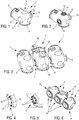
- a module 1 equipped with the invention comprises, according to the Figure 1 , a tank 2, in which a single-phase conductor is contained.
- the tank 2 comprises two openings 3 and 4, here at a right angle, for the passage of the conductor, which will extend along the dotted lines of axis of these openings 3 and 4, making here an angle.
- the openings 3 and 4 are provided with bolting flanges to corresponding flanges of other elements in extension of the apparatus.
- the module 1 is almost symmetrical with respect to a median plane defined by the axes of the openings 3 and 4, and in which the single-phase conductor extends.
- bosses 5 and 6 adapted to form pressure taps and both of which comprise a continuous end face and flat.
- the bosses 5 and 6 protrude from the tank 2 outwardly in opposite directions, and are aligned. They can be massive or concave to the tank 2; however, they are continuous and therefore impervious to the initial state.
- Third pressure-relief bosses 9 are still established, on the median plane of the module 1, between the openings 3 and 4, and also between the first pressure-tapping bosses 5 and 6. They also have an end face 7 continuous and flat. While the bosses 5 and 9 are cylindrical, the bosses 6 are distinguished in that the end face 7 is on a collar 10. The opposing bosses 5 and 6 have the same radius at their end faces 7, the bosses 6 being thinner at the groove 8 connecting the flange 10 to the tank 2.
- the junction of three single-phase conductors comprises three modules 1 contiguous and attached to each other.
- the bosses 5 and 6 of the three modules 1 are all in alignment, and two pairs 11, each comprising a boss 5 and a butted boss 6, extend between the consecutive modules 1.
- the bosses 5 and 6 of the pairs 11 have been machined, according to the Figure 2 by piercing them from the end faces 7 to the gaseous compartment through the tank 2, and providing, around the recesses 14 obtained, other bores 12 on the parts remaining from the end faces 7.
- These bores 12, which may or may not be threaded, are intended to receive bolts 13 for assembling the modules 1 by the pairs 11.
- One of the third bosses 9 is machined in the same way, forming a recess 14 and fixing holes 12, in order to adjust equipment such as a rupture disk 20 against overpressure in the gas compartment common to the modules 1 assembled.
- Other equipment such as a filling valve 21 of the gas compartment and a densistat 22 (pressure monitoring equipment of the compartment) are also installed, in a single copy each. This equipment can be concentrated on only one of the modules 1 (what is represented here), or, on the contrary, distributed over several of them, and present or not on the third bosses 9.
- the Figure 5 shows that the holes 12 machined in the cylindrical bosses 5 are threaded and thus receive the threaded rods of the bolts 13; the flanges 10 of the opposite bosses 6 are traversed by the same rods at their bores 12 ( Figure 4 ), which allows the bolts 13 to clamp the collar 10 on the cylindrical boss 5.
- the Figure 6 illustrates another embodiment, where the modules, now 15, have an additional opening 16 in the extension of one of the openings 3 already encountered; these are modules in the form of cross, allowing a bifurcation of single-phase conductors and to which the invention can still be applied, the third opening 16 also belonging to the median plane mentioned.
- junctions of the modules 1 or 15 are rigid and easily sealed.
Landscapes
- Engineering & Computer Science (AREA)
- Power Engineering (AREA)
- Gas-Insulated Switchgears (AREA)
- Installation Of Bus-Bars (AREA)
Claims (9)
- Einphasenleitermodul (1, 15) für ein gasisoliertes Mittel- oder Hochspannungsgerät, umfassend ein Gefäß, das den Leiter in einem Gasfach enthält, umfassend auf zwei entgegengesetzten Seite einer Mittelebene, in der sich der Leiter erstreckt, Vorsprünge (5, 6), die auf dem Gefäß vorgesehen und dazu ausgelegt sind, Druckabzweigstellen zu bilden, die zur Außenseite des Gefäßes hin vorstehen, dadurch gekennzeichnet, dass die Vorsprünge (5, 6) durchgehend sind, wobei eine Abdichtung des Gefäßes mit einer Außenumgebung durch sie beibehalten wird, und dass sie Endflächen (7) mit komplementären Formen umfassen, die ebenfalls durchgehend sind.
- Einphasenleitermodul nach Anspruch 1, dadurch gekennzeichnet, dass die Endflächen (7) flach sind.
- Einphasenleitermodul nach Anspruch 1 oder 2, dadurch gekennzeichnet, dass die Vorsprünge (5, 6) ausgerichtet sind.
- Einphasenleitermodul nach einem der Ansprüche 1 bis 3, dadurch gekennzeichnet, dass die Endfläche (7) wenigstens einer Abzweigung einen Kragen (10) bildet.
- Leitermodul nach einem der Ansprüche 1 bis 4, dadurch gekennzeichnet, dass es an der Mittelebene einen an dem Gefäß vorgesehenen dritten Vorsprung (9) zur Druckabzweigung umfasst, der zur Außenseite des Gefäßes hin vorsteht und eine flache und durchgehende Endfläche (7) umfasst.
- Einphasenleiteranschluss in einem gasisolierten Mittel- oder Hochspannungsgerät, dadurch gekennzeichnet, dass es durch Module nach einem der Ansprüche 1 bis 5 gebildet ist, wobei die Vorsprünge (5, 6) zur Druckabzweigung ausgerichtet sind und verbundene Paare (11) umfassen, wobei die Vorsprünge der Paare (11) dazu gefertigt worden sind, sie zu öffnen und hierbei die Innenräume der Module in Verbindung miteinander zu bringen, wobei zwei der Vorsprünge zur Druckabzweigung, die zu keinem der Paare gehören und an den Enden der Ausrichtung angeordnet sind, die Endfläche durchgehend halten.
- Einphasenleiteranschluss nach Anspruch 6, dadurch gekennzeichnet, dass die Vorsprünge der Paare (11) ferner dazu gefertigt worden sind, Bohrungen (12) für Schrauben (13) aufzunehmen, die die Module miteinander verbinden.
- Einphasenleiteranschluss nach einem der Ansprüche 6 oder 7, dadurch gekennzeichnet, dass er ein einziges Exemplar von Geräten (20, 21, 22) umfasst, umfassend einen Densistat, ein Füllventil oder eine Berstscheibe.
- Einphasenleiteranschluss nach Anspruch 8, wobei die Module gemäß Anspruch 5 sind, dadurch gekennzeichnet, dass wenigstens eines der Geräte an wenigstens einem der dritten Vorsprünge (9) angeordnet ist, der dazu gefertigt worden ist, ihn zu öffnen.
Applications Claiming Priority (2)
| Application Number | Priority Date | Filing Date | Title |
|---|---|---|---|
| FR1358642A FR3010583A1 (fr) | 2013-09-09 | 2013-09-09 | Module de conducteur monophase et jonction de conducteurs monophases equipee de ces modules |
| PCT/EP2014/069133 WO2015032957A1 (fr) | 2013-09-09 | 2014-09-09 | Module de conducteur monophase et jonction de conducteurs monophases equipee de ces modules |
Publications (3)
| Publication Number | Publication Date |
|---|---|
| EP3044841A1 EP3044841A1 (de) | 2016-07-20 |
| EP3044841B1 true EP3044841B1 (de) | 2017-07-05 |
| EP3044841B8 EP3044841B8 (de) | 2017-08-30 |
Family
ID=49551636
Family Applications (1)
| Application Number | Title | Priority Date | Filing Date |
|---|---|---|---|
| EP14766135.9A Not-in-force EP3044841B8 (de) | 2013-09-09 | 2014-09-09 | Einphasenleitermodul und einphasenleiteranschluss mit diesen modulen |
Country Status (3)
| Country | Link |
|---|---|
| EP (1) | EP3044841B8 (de) |
| FR (1) | FR3010583A1 (de) |
| WO (1) | WO2015032957A1 (de) |
Families Citing this family (1)
| Publication number | Priority date | Publication date | Assignee | Title |
|---|---|---|---|---|
| CN106785944B (zh) * | 2016-12-12 | 2018-10-19 | 江苏安靠智能输电工程科技股份有限公司 | 一种三相共体刚性气体绝缘输电线路 |
Family Cites Families (3)
| Publication number | Priority date | Publication date | Assignee | Title |
|---|---|---|---|---|
| KR900002891B1 (ko) * | 1984-12-29 | 1990-05-01 | 미쯔비시 덴끼 가부시기가이샤 | 가스절연 개폐장치 |
| DE4320906C2 (de) * | 1993-06-18 | 2000-07-27 | Siemens Ag | Gehäuse für einen druckgasisolierten Hochspannungs- Leistungs-Schalter |
| DE102007006729A1 (de) * | 2007-02-06 | 2008-08-07 | Siemens Ag | Kapselungsabschnitt einer gasisolierten Hochspannungsanlage |
-
2013
- 2013-09-09 FR FR1358642A patent/FR3010583A1/fr active Pending
-
2014
- 2014-09-09 EP EP14766135.9A patent/EP3044841B8/de not_active Not-in-force
- 2014-09-09 WO PCT/EP2014/069133 patent/WO2015032957A1/fr not_active Ceased
Non-Patent Citations (1)
| Title |
|---|
| None * |
Also Published As
| Publication number | Publication date |
|---|---|
| EP3044841B8 (de) | 2017-08-30 |
| EP3044841A1 (de) | 2016-07-20 |
| FR3010583A1 (fr) | 2015-03-13 |
| WO2015032957A1 (fr) | 2015-03-12 |
Similar Documents
| Publication | Publication Date | Title |
|---|---|---|
| EP2909906B1 (de) | Elektrische vorrichtung mit leiterträger zwischen zwei kapselungsteilen | |
| EP3044841B1 (de) | Einphasenleitermodul und einphasenleiteranschluss mit diesen modulen | |
| CA3051804A1 (fr) | Reacteur nucleaire integrant un echangeur de chaleur primaire de securite | |
| EP2929132B1 (de) | Elektrische vorrichtung zur bohrlochstimulation | |
| EP0128452B1 (de) | Modular-Röhrenbündel für Dampfkondensator und Dampfkondensator mit einem solchen Bündel | |
| FR2663400A3 (fr) | Barre creuse pour la canalisation et la distribution de fluides en general. | |
| EP2325939B1 (de) | Vorrichtung zum Multiplexen von thermisch optimierten Hyperfrequenzkanälen | |
| EP3172474B1 (de) | Dehnungsfuge für eine gasisolierte hülle mit endlastausgleich | |
| EP1624470B1 (de) | Dreiphasenstromwandler und elektrische Station mit einem solchen Stromwandler | |
| WO2016180895A1 (fr) | Enceinte étanche pour le confinement sous-marin d'un appareillage | |
| FR3020187A1 (fr) | Dispositif de raccordement pour deux appareillages electriques a isolation gazeuse | |
| FR3005936A1 (fr) | Plaque de support pour le passage de systemes entre deux zones a pressurisations differentes d'un aeronef. | |
| FR2642578A1 (fr) | Ligne blindee | |
| WO2022185016A1 (fr) | Dispositif de liquefaction de gaz et procede d'assemblage d'un tel dispositif | |
| CA2391667C (fr) | Pole de disjoncteur a gaz sous pression pouvant etre assemble et desassemble sans perte de gaz appreciable | |
| EP4455543B1 (de) | Tank mit innen- und aussenräumen sowie mindestens einer zweiteiligen rohrschnittstelle, die den innen- und aussenraum durchquert | |
| EP1195871B1 (de) | Mehrphasige druckgasisolierte Leitung und Anschlussmodule für ein-oder mehrphasige Durchführung in einer solchen Leitung | |
| EP3074702B1 (de) | Trägerelement, entsprechende kryogene flüssigkeitsschaltung und entsprechendes verfahren | |
| EP3097618A1 (de) | Gehäuseelement einer schaltvorrichtung zur unterbrechung oder isolation einer schaltung, gehäuse solch einer schaltvorrichtung und verfahren zur herstellung einer derartigen schaltvorrichtung | |
| FR3043267A1 (fr) | Dispositif de confinement d'une fuite d'un gaz au niveau d'une zone de changement de diametre d'un conduit | |
| FR2813452A1 (fr) | Cloison etanche de compartimentage et installation electrique blindee triphasee a isolation gazeuse pourvue d' une telle cloison | |
| WO2020025894A1 (fr) | Echangeur thermique pour turbomachine | |
| FR3152311A1 (fr) | Dispositif de contrôlr thermique redondant de grande longueur à structures diphasiques complexes, procédé d'assemblage et procédé de fabrication | |
| FR3066864A1 (fr) | Machine electrique comprenant un bornier de raccordement electrique | |
| FR2647598A1 (fr) | Dispositif thermoelectrique fonctionnant entre deux ecoulements de fluides, l'un gazeux, l'autre liquide |
Legal Events
| Date | Code | Title | Description |
|---|---|---|---|
| PUAI | Public reference made under article 153(3) epc to a published international application that has entered the european phase |
Free format text: ORIGINAL CODE: 0009012 |
|
| 17P | Request for examination filed |
Effective date: 20160311 |
|
| AK | Designated contracting states |
Kind code of ref document: A1 Designated state(s): AL AT BE BG CH CY CZ DE DK EE ES FI FR GB GR HR HU IE IS IT LI LT LU LV MC MK MT NL NO PL PT RO RS SE SI SK SM TR |
|
| AX | Request for extension of the european patent |
Extension state: BA ME |
|
| DAX | Request for extension of the european patent (deleted) | ||
| GRAP | Despatch of communication of intention to grant a patent |
Free format text: ORIGINAL CODE: EPIDOSNIGR1 |
|
| STAA | Information on the status of an ep patent application or granted ep patent |
Free format text: STATUS: GRANT OF PATENT IS INTENDED |
|
| INTG | Intention to grant announced |
Effective date: 20170217 |
|
| GRAS | Grant fee paid |
Free format text: ORIGINAL CODE: EPIDOSNIGR3 |
|
| GRAA | (expected) grant |
Free format text: ORIGINAL CODE: 0009210 |
|
| STAA | Information on the status of an ep patent application or granted ep patent |
Free format text: STATUS: THE PATENT HAS BEEN GRANTED |
|
| AK | Designated contracting states |
Kind code of ref document: B1 Designated state(s): AL AT BE BG CH CY CZ DE DK EE ES FI FR GB GR HR HU IE IS IT LI LT LU LV MC MK MT NL NO PL PT RO RS SE SI SK SM TR |
|
| REG | Reference to a national code |
Ref country code: GB Ref legal event code: FG4D Free format text: NOT ENGLISH |
|
| REG | Reference to a national code |
Ref country code: CH Ref legal event code: EP Ref country code: CH Ref legal event code: NV Representative=s name: BOVARD AG PATENT- UND MARKENANWAELTE, CH |
|
| REG | Reference to a national code |
Ref country code: AT Ref legal event code: REF Ref document number: 907199 Country of ref document: AT Kind code of ref document: T Effective date: 20170715 |
|
| REG | Reference to a national code |
Ref country code: IE Ref legal event code: FG4D Free format text: LANGUAGE OF EP DOCUMENT: FRENCH |
|
| RAP2 | Party data changed (patent owner data changed or rights of a patent transferred) |
Owner name: GENERAL ELECTRIC TECHNOLOGY GMBH |
|
| REG | Reference to a national code |
Ref country code: DE Ref legal event code: R096 Ref document number: 602014011547 Country of ref document: DE |
|
| REG | Reference to a national code |
Ref country code: DE Ref legal event code: R082 Ref document number: 602014011547 Country of ref document: DE Representative=s name: BETTEN & RESCH PATENT- UND RECHTSANWAELTE PART, DE |
|
| REG | Reference to a national code |
Ref country code: CH Ref legal event code: PFA Owner name: GENERAL ELECTRIC TECHNOLOGY GMBH, CH Free format text: FORMER OWNER: ALSTOM TECHNOLOGY LTD, CH |
|
| REG | Reference to a national code |
Ref country code: FR Ref legal event code: PLFP Year of fee payment: 4 |
|
| PGFP | Annual fee paid to national office [announced via postgrant information from national office to epo] |
Ref country code: FR Payment date: 20170925 Year of fee payment: 4 Ref country code: CH Payment date: 20170927 Year of fee payment: 4 |
|
| REG | Reference to a national code |
Ref country code: NL Ref legal event code: MP Effective date: 20170705 |
|
| REG | Reference to a national code |
Ref country code: AT Ref legal event code: MK05 Ref document number: 907199 Country of ref document: AT Kind code of ref document: T Effective date: 20170705 |
|
| REG | Reference to a national code |
Ref country code: LT Ref legal event code: MG4D |
|
| PG25 | Lapsed in a contracting state [announced via postgrant information from national office to epo] |
Ref country code: FI Free format text: LAPSE BECAUSE OF FAILURE TO SUBMIT A TRANSLATION OF THE DESCRIPTION OR TO PAY THE FEE WITHIN THE PRESCRIBED TIME-LIMIT Effective date: 20170705 Ref country code: NL Free format text: LAPSE BECAUSE OF FAILURE TO SUBMIT A TRANSLATION OF THE DESCRIPTION OR TO PAY THE FEE WITHIN THE PRESCRIBED TIME-LIMIT Effective date: 20170705 Ref country code: LT Free format text: LAPSE BECAUSE OF FAILURE TO SUBMIT A TRANSLATION OF THE DESCRIPTION OR TO PAY THE FEE WITHIN THE PRESCRIBED TIME-LIMIT Effective date: 20170705 Ref country code: HR Free format text: LAPSE BECAUSE OF FAILURE TO SUBMIT A TRANSLATION OF THE DESCRIPTION OR TO PAY THE FEE WITHIN THE PRESCRIBED TIME-LIMIT Effective date: 20170705 Ref country code: NO Free format text: LAPSE BECAUSE OF FAILURE TO SUBMIT A TRANSLATION OF THE DESCRIPTION OR TO PAY THE FEE WITHIN THE PRESCRIBED TIME-LIMIT Effective date: 20171005 Ref country code: AT Free format text: LAPSE BECAUSE OF FAILURE TO SUBMIT A TRANSLATION OF THE DESCRIPTION OR TO PAY THE FEE WITHIN THE PRESCRIBED TIME-LIMIT Effective date: 20170705 Ref country code: SE Free format text: LAPSE BECAUSE OF FAILURE TO SUBMIT A TRANSLATION OF THE DESCRIPTION OR TO PAY THE FEE WITHIN THE PRESCRIBED TIME-LIMIT Effective date: 20170705 |
|
| PGFP | Annual fee paid to national office [announced via postgrant information from national office to epo] |
Ref country code: DE Payment date: 20170927 Year of fee payment: 4 |
|
| PG25 | Lapsed in a contracting state [announced via postgrant information from national office to epo] |
Ref country code: RS Free format text: LAPSE BECAUSE OF FAILURE TO SUBMIT A TRANSLATION OF THE DESCRIPTION OR TO PAY THE FEE WITHIN THE PRESCRIBED TIME-LIMIT Effective date: 20170705 Ref country code: BG Free format text: LAPSE BECAUSE OF FAILURE TO SUBMIT A TRANSLATION OF THE DESCRIPTION OR TO PAY THE FEE WITHIN THE PRESCRIBED TIME-LIMIT Effective date: 20171005 Ref country code: LV Free format text: LAPSE BECAUSE OF FAILURE TO SUBMIT A TRANSLATION OF THE DESCRIPTION OR TO PAY THE FEE WITHIN THE PRESCRIBED TIME-LIMIT Effective date: 20170705 Ref country code: IS Free format text: LAPSE BECAUSE OF FAILURE TO SUBMIT A TRANSLATION OF THE DESCRIPTION OR TO PAY THE FEE WITHIN THE PRESCRIBED TIME-LIMIT Effective date: 20171105 Ref country code: GR Free format text: LAPSE BECAUSE OF FAILURE TO SUBMIT A TRANSLATION OF THE DESCRIPTION OR TO PAY THE FEE WITHIN THE PRESCRIBED TIME-LIMIT Effective date: 20171006 Ref country code: ES Free format text: LAPSE BECAUSE OF FAILURE TO SUBMIT A TRANSLATION OF THE DESCRIPTION OR TO PAY THE FEE WITHIN THE PRESCRIBED TIME-LIMIT Effective date: 20170705 Ref country code: PL Free format text: LAPSE BECAUSE OF FAILURE TO SUBMIT A TRANSLATION OF THE DESCRIPTION OR TO PAY THE FEE WITHIN THE PRESCRIBED TIME-LIMIT Effective date: 20170705 |
|
| REG | Reference to a national code |
Ref country code: DE Ref legal event code: R097 Ref document number: 602014011547 Country of ref document: DE |
|
| PG25 | Lapsed in a contracting state [announced via postgrant information from national office to epo] |
Ref country code: RO Free format text: LAPSE BECAUSE OF FAILURE TO SUBMIT A TRANSLATION OF THE DESCRIPTION OR TO PAY THE FEE WITHIN THE PRESCRIBED TIME-LIMIT Effective date: 20170705 Ref country code: CZ Free format text: LAPSE BECAUSE OF FAILURE TO SUBMIT A TRANSLATION OF THE DESCRIPTION OR TO PAY THE FEE WITHIN THE PRESCRIBED TIME-LIMIT Effective date: 20170705 Ref country code: DK Free format text: LAPSE BECAUSE OF FAILURE TO SUBMIT A TRANSLATION OF THE DESCRIPTION OR TO PAY THE FEE WITHIN THE PRESCRIBED TIME-LIMIT Effective date: 20170705 |
|
| PLBE | No opposition filed within time limit |
Free format text: ORIGINAL CODE: 0009261 |
|
| STAA | Information on the status of an ep patent application or granted ep patent |
Free format text: STATUS: NO OPPOSITION FILED WITHIN TIME LIMIT |
|
| PG25 | Lapsed in a contracting state [announced via postgrant information from national office to epo] |
Ref country code: EE Free format text: LAPSE BECAUSE OF FAILURE TO SUBMIT A TRANSLATION OF THE DESCRIPTION OR TO PAY THE FEE WITHIN THE PRESCRIBED TIME-LIMIT Effective date: 20170705 Ref country code: SK Free format text: LAPSE BECAUSE OF FAILURE TO SUBMIT A TRANSLATION OF THE DESCRIPTION OR TO PAY THE FEE WITHIN THE PRESCRIBED TIME-LIMIT Effective date: 20170705 Ref country code: IT Free format text: LAPSE BECAUSE OF FAILURE TO SUBMIT A TRANSLATION OF THE DESCRIPTION OR TO PAY THE FEE WITHIN THE PRESCRIBED TIME-LIMIT Effective date: 20170705 Ref country code: MC Free format text: LAPSE BECAUSE OF FAILURE TO SUBMIT A TRANSLATION OF THE DESCRIPTION OR TO PAY THE FEE WITHIN THE PRESCRIBED TIME-LIMIT Effective date: 20170705 Ref country code: SM Free format text: LAPSE BECAUSE OF FAILURE TO SUBMIT A TRANSLATION OF THE DESCRIPTION OR TO PAY THE FEE WITHIN THE PRESCRIBED TIME-LIMIT Effective date: 20170705 |
|
| 26N | No opposition filed |
Effective date: 20180406 |
|
| REG | Reference to a national code |
Ref country code: IE Ref legal event code: MM4A |
|
| REG | Reference to a national code |
Ref country code: BE Ref legal event code: MM Effective date: 20170930 |
|
| PG25 | Lapsed in a contracting state [announced via postgrant information from national office to epo] |
Ref country code: LU Free format text: LAPSE BECAUSE OF NON-PAYMENT OF DUE FEES Effective date: 20170909 |
|
| PG25 | Lapsed in a contracting state [announced via postgrant information from national office to epo] |
Ref country code: IE Free format text: LAPSE BECAUSE OF NON-PAYMENT OF DUE FEES Effective date: 20170909 |
|
| PG25 | Lapsed in a contracting state [announced via postgrant information from national office to epo] |
Ref country code: SI Free format text: LAPSE BECAUSE OF FAILURE TO SUBMIT A TRANSLATION OF THE DESCRIPTION OR TO PAY THE FEE WITHIN THE PRESCRIBED TIME-LIMIT Effective date: 20170705 Ref country code: BE Free format text: LAPSE BECAUSE OF NON-PAYMENT OF DUE FEES Effective date: 20170930 |
|
| PG25 | Lapsed in a contracting state [announced via postgrant information from national office to epo] |
Ref country code: MT Free format text: LAPSE BECAUSE OF FAILURE TO SUBMIT A TRANSLATION OF THE DESCRIPTION OR TO PAY THE FEE WITHIN THE PRESCRIBED TIME-LIMIT Effective date: 20170705 |
|
| REG | Reference to a national code |
Ref country code: DE Ref legal event code: R119 Ref document number: 602014011547 Country of ref document: DE |
|
| REG | Reference to a national code |
Ref country code: CH Ref legal event code: PL |
|
| GBPC | Gb: european patent ceased through non-payment of renewal fee |
Effective date: 20180909 |
|
| PG25 | Lapsed in a contracting state [announced via postgrant information from national office to epo] |
Ref country code: HU Free format text: LAPSE BECAUSE OF FAILURE TO SUBMIT A TRANSLATION OF THE DESCRIPTION OR TO PAY THE FEE WITHIN THE PRESCRIBED TIME-LIMIT; INVALID AB INITIO Effective date: 20140909 |
|
| PG25 | Lapsed in a contracting state [announced via postgrant information from national office to epo] |
Ref country code: DE Free format text: LAPSE BECAUSE OF NON-PAYMENT OF DUE FEES Effective date: 20190402 |
|
| PG25 | Lapsed in a contracting state [announced via postgrant information from national office to epo] |
Ref country code: LI Free format text: LAPSE BECAUSE OF NON-PAYMENT OF DUE FEES Effective date: 20180930 Ref country code: CH Free format text: LAPSE BECAUSE OF NON-PAYMENT OF DUE FEES Effective date: 20180930 Ref country code: FR Free format text: LAPSE BECAUSE OF NON-PAYMENT OF DUE FEES Effective date: 20180930 |
|
| PG25 | Lapsed in a contracting state [announced via postgrant information from national office to epo] |
Ref country code: CY Free format text: LAPSE BECAUSE OF FAILURE TO SUBMIT A TRANSLATION OF THE DESCRIPTION OR TO PAY THE FEE WITHIN THE PRESCRIBED TIME-LIMIT Effective date: 20170705 Ref country code: GB Free format text: LAPSE BECAUSE OF NON-PAYMENT OF DUE FEES Effective date: 20180909 |
|
| PG25 | Lapsed in a contracting state [announced via postgrant information from national office to epo] |
Ref country code: MK Free format text: LAPSE BECAUSE OF FAILURE TO SUBMIT A TRANSLATION OF THE DESCRIPTION OR TO PAY THE FEE WITHIN THE PRESCRIBED TIME-LIMIT Effective date: 20170705 |
|
| PG25 | Lapsed in a contracting state [announced via postgrant information from national office to epo] |
Ref country code: TR Free format text: LAPSE BECAUSE OF FAILURE TO SUBMIT A TRANSLATION OF THE DESCRIPTION OR TO PAY THE FEE WITHIN THE PRESCRIBED TIME-LIMIT Effective date: 20170705 |
|
| PG25 | Lapsed in a contracting state [announced via postgrant information from national office to epo] |
Ref country code: PT Free format text: LAPSE BECAUSE OF FAILURE TO SUBMIT A TRANSLATION OF THE DESCRIPTION OR TO PAY THE FEE WITHIN THE PRESCRIBED TIME-LIMIT Effective date: 20170705 |
|
| PG25 | Lapsed in a contracting state [announced via postgrant information from national office to epo] |
Ref country code: AL Free format text: LAPSE BECAUSE OF FAILURE TO SUBMIT A TRANSLATION OF THE DESCRIPTION OR TO PAY THE FEE WITHIN THE PRESCRIBED TIME-LIMIT Effective date: 20170705 |