EP3045262A1 - Griffe d'ancrage pour tubes d'échangeurs thermiques - Google Patents
Griffe d'ancrage pour tubes d'échangeurs thermiques Download PDFInfo
- Publication number
- EP3045262A1 EP3045262A1 EP15000099.0A EP15000099A EP3045262A1 EP 3045262 A1 EP3045262 A1 EP 3045262A1 EP 15000099 A EP15000099 A EP 15000099A EP 3045262 A1 EP3045262 A1 EP 3045262A1
- Authority
- EP
- European Patent Office
- Prior art keywords
- clamping sleeve
- anchoring claw
- claw according
- heat exchanger
- carrier region
- Prior art date
- Legal status (The legal status is an assumption and is not a legal conclusion. Google has not performed a legal analysis and makes no representation as to the accuracy of the status listed.)
- Granted
Links
Images


Classifications
-
- B—PERFORMING OPERATIONS; TRANSPORTING
- B23—MACHINE TOOLS; METAL-WORKING NOT OTHERWISE PROVIDED FOR
- B23P—METAL-WORKING NOT OTHERWISE PROVIDED FOR; COMBINED OPERATIONS; UNIVERSAL MACHINE TOOLS
- B23P19/00—Machines for simply fitting together or separating metal parts or objects, or metal and non-metal parts, whether or not involving some deformation; Tools or devices therefor so far as not provided for in other classes
- B23P19/02—Machines for simply fitting together or separating metal parts or objects, or metal and non-metal parts, whether or not involving some deformation; Tools or devices therefor so far as not provided for in other classes for connecting objects by press fit or for detaching same
- B23P19/025—For detaching only
-
- B—PERFORMING OPERATIONS; TRANSPORTING
- B23—MACHINE TOOLS; METAL-WORKING NOT OTHERWISE PROVIDED FOR
- B23P—METAL-WORKING NOT OTHERWISE PROVIDED FOR; COMBINED OPERATIONS; UNIVERSAL MACHINE TOOLS
- B23P19/00—Machines for simply fitting together or separating metal parts or objects, or metal and non-metal parts, whether or not involving some deformation; Tools or devices therefor so far as not provided for in other classes
- B23P19/02—Machines for simply fitting together or separating metal parts or objects, or metal and non-metal parts, whether or not involving some deformation; Tools or devices therefor so far as not provided for in other classes for connecting objects by press fit or for detaching same
- B23P19/022—Extracting or inserting relatively long parts
-
- B—PERFORMING OPERATIONS; TRANSPORTING
- B25—HAND TOOLS; PORTABLE POWER-DRIVEN TOOLS; MANIPULATORS
- B25B—TOOLS OR BENCH DEVICES NOT OTHERWISE PROVIDED FOR, FOR FASTENING, CONNECTING, DISENGAGING, OR HOLDING
- B25B5/00—Clamps
- B25B5/06—Arrangements for positively actuating jaws
- B25B5/061—Arrangements for positively actuating jaws with fluid drive
- B25B5/065—Arrangements for positively actuating jaws with fluid drive involving the use of flexible pressure bags or diaphragms
-
- F—MECHANICAL ENGINEERING; LIGHTING; HEATING; WEAPONS; BLASTING
- F01—MACHINES OR ENGINES IN GENERAL; ENGINE PLANTS IN GENERAL; STEAM ENGINES
- F01K—STEAM ENGINE PLANTS; STEAM ACCUMULATORS; ENGINE PLANTS NOT OTHERWISE PROVIDED FOR; ENGINES USING SPECIAL WORKING FLUIDS OR CYCLES
- F01K5/00—Plants characterised by use of means for storing steam in an alkali to increase steam pressure, e.g. of Honigmann or Koenemann type
-
- F—MECHANICAL ENGINEERING; LIGHTING; HEATING; WEAPONS; BLASTING
- F28—HEAT EXCHANGE IN GENERAL
- F28F—DETAILS OF HEAT-EXCHANGE AND HEAT-TRANSFER APPARATUS, OF GENERAL APPLICATION
- F28F11/00—Arrangements for sealing leaky tubes and conduits
Definitions
- the invention relates to an anchoring claw for heat exchanger tubes, comprising a hollow cylindrical clamping sleeve made of a resilient material, wherein the clamping sleeve along its axial extent at least one axially slotted support portion and wherein in the interior of the clamping sleeve pressure means for widening the diameter of the support region are provided so as to provide a Apply pressure from the radial outer surface of the carrier region of the clamping sleeve on the inner wall of a surrounding heat exchanger tube with adapted to the outer diameter of the clamping sleeve inner diameter.
- a steam generator comprises a plurality, for example a few hundred, of preferably parallel-aligned steam generator tubes, which for example have an inner diameter of 20 mm and a length of a few meters. At their ends, the steam generator tubes are welded to a respective perforated bottom plate of a surrounding container, so that the steam generator tubes the container hermetically pass through this separated and a heat exchanger or a steam generator is formed.
- the steam generator pipe In case of a detected defect of a pipe, such as a crack, the steam generator pipe is to be pulled out of the steam generator and repaired or replaced by another steam generator pipe. But even for purely analytical purposes, it may be necessary to extract a steam generator tube from the steam generator.
- a screw-in claw is used for this purpose, for example, which is screwed by means of a screwing with a certain torque to an accessible end of the steam generator tube to be pulled.
- a screwing with a certain torque to an accessible end of the steam generator tube to be pulled.
- initially provided at the accessible end of the steam generator tube weld joint with the bottom plate.
- the Einschraub Scheme is heat treated by line seams, so that the screw-in end of the steam generator tube is softer.
- the disadvantage here is the need for a very complex, time-consuming and sensitive approach.
- it can come to an increase in diameter of the steam generator tube by the high radial pressure of Einschraubkralle, which is not controllable during the drawing process.
- a Einschraubkralle can only be used at one end of a steam generator tube.
- an anchoring claw of the type mentioned is introduced by means of a guide mechanism in a pulled out steam generator tube and set by means of a hydraulic fluid under pressure, stretched and pulled.
- Such anchoring claw is for example in the patent DE 69712396 T2 disclosed.
- such an anchoring claw is applied precisely to a defective point of the steam generator tube in order to stabilize it mechanically.
- the disadvantage here is that it can come by tightening the anchoring claw, so the radial expansion of the clamping sleeve, to a significant expansion of the drawing steam generator tube, whereby the structural integrity is further weakened. Since such an anchoring claw can also be used for example in the middle of a steam generator tube, there is the additional problem that a widened steam generator tube can not be pulled through the associated hole of the perforated bottom plate of the steam generator during the drawing process at its widened position. The excessive widening of a weakened spot also prevents the safe analysis of the defect.
- an object of the invention to provide an anchoring claw, which minimizes the risk of tube breakage when pulling or removing a steam generator tube and in which an increase in diameter of the steam generator tube is as small as possible.
- an anchoring claw for steam generator tubes of the aforementioned type is characterized in that the radial outer surface of the carrier region of the hollow cylindrical clamping sleeve raised areas wherein the cumulative portion of the raised areas on the radial total outer surface of the carrier area is in the range of 2% to 25%. All non-raised areas here have the same radial distance to the central axis in the unexpanded state of the clamping sleeve.
- the raised areas are to be regarded as press-in surfaces, which undergo a positive connection with the pipe wall under pressure when exceeding the permissible surface pressure of the respective steam generator tube with local deformation of the inside of the pipe wall.
- the material of the clamping sleeve is harder to choose than that of a wall of a steam generator tube.
- the support portion of the clamping sleeve is milled, that is, the non-raised areas are milled during manufacture, so that the raised areas remain as press-in surfaces.
- the carrier region is the radial slotted outer region of a clamping sleeve, which is provided with press-in surfaces and can be widened in its diameter by means of a pressure device.
- the clamping sleeve is somewhat thicker wall in this area than in the transition areas to the unslotted areas, which are ideally somewhat more flexible.
- a clamping sleeve for example, have 6 to 16 slots.
- the slit can also be made longer than the actual support area.
- its outside diameter must be slightly smaller, for example by 0.2 mm to 1.5 mm, than the inside diameter of the steam generator tube to be drawn, for example 20 mm.
- the basic idea of the invention is that the percentage of press-fit surfaces on the radially outer overall surface of the carrier region is clearly opposite the usual value of 50% - as is customary in a thread - is reduced.
- the lower limit of the stated value range of 2% to 25% results from the minimum required strength of the raised regions relative to shear forces and the upper limit from the fact that the advantage according to the invention is increasingly relativised here.
- a particularly preferred value range for the summary portion of the raised areas on the radial total outer surface of the carrier area is between 5% and 20%.
- the raised areas are plateau-like pronounced.
- This has the advantage that the respective elevations thereby obtained in comparison to a pointed shape increased mechanical stability to shear forces. This is of particular importance against the background of the inventively reduced share of collected areas.
- the raised areas have a stretched (base area) shape, which extends at least predominantly transversely to the axial extension of the clamping sleeve.
- the tensile load when pulling out a steam generator tube acts axially.
- a transverse to the axial direction arranged elongated course of the raised areas improved tensile stress is achieved.
- raised areas may be arranged ring-like around the support area. This has the manufacturing advantage that the ratio of the base area of the raised areas to the total outer area of the support area can be easily influenced by appropriate selection of the width of the raised areas and the axial distance between adjacent raised rings.
- a plurality of raised areas are arranged spirally or ring-like, wherein the spiral shape also extends beyond the slots of the clamping sleeve.
- the width of the raised areas along the axial extent of the clamping sleeve is between 0.1mm and 1mm. Assuming elongated and predominantly transverse areas, their maximum shear force is determined by their width. On the other hand, the maximum shear force is also determined by the corresponding positive recess in the wall of the steam generator tube.
- the width of a survey is to be selected such that the maximum shear force achievable thereby corresponds to the maximum shear force in the corresponding positive recess of the pipe wall.
- a manufacturing limit for a minimum width is about 0.1mm.
- the maximum shear force of the survey is typically greater than that of the corresponding well.
- preferred ranges may result, for example a width in the range of 0.15 mm to 0.25 mm.
- the raised areas along the axial extent of the clamping sleeve on a cross-section which is pronounced trapezoidal.
- the radial height of the raised areas of the outer surface relative to the remaining outer surface of the carrier area is increased in the range of 0.2 mm to 0.5 mm. This results in penetration depths of about 0.1 mm to 0.4 mm, which prove to be particularly suitable.
- Such expansion of the clamping sleeve, that even the non-raised areas contact the inner wall of the steam pipe, is preferably to be avoided.
- the clamping sleeve is made of hardened steel, which is harder than the material of a typical steam generator tube, so as to ensure a trouble-free positive penetration of a survey in the pipe wall.
- Hardened steel has proven particularly suitable.
- the pressure means comprise a first and a second nested plastic tube, which are arranged in the interior of the clamping sleeve at least in the carrier area and which are delimited by axial end elements, so that a closed interior is formed, by applying pressure is radially expandable.
- Plastic has a sufficiently high elasticity for a radial expansion. Due to the double-walledness of the form-fitting nested tubes, their mechanical stability is given despite their elasticity.
- the plastic pipes are made of the material Vibratha ne.
- the closed space is filled with water, which serves as hydraulic fluid.
- water which serves as hydraulic fluid.
- a neutral hydraulic fluid such as water is beneficial.
- a hydraulic pump In order to be able to exert a corresponding pressure on the closed space, a hydraulic pump is provided, which is fluidically connected to the closed space. Due to the invention achieved reduction of the required pressure, for example, already 200 bar maximum pressure of the hydraulic pump may prove sufficient.
- two axially slotted carrier regions spaced axially with an intermediate region are provided.
- the pipe area is stabilized with the defect in addition to an advantageous manner. A widening of both support areas can be done by one and the same pressure medium.
- an eddy current probe is provided in the intermediate region, which is suitable for detecting defective regions of a heat exchanger tube surrounding the clamping sleeve.
- the anchoring claw this is connected at one of its axial ends with a Greifziehstange or a Greifziehseil.
- a connection to a pulling device is possible by means of which the anchoring claw can be pulled together with a steam generator tube.
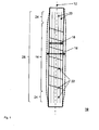
- Fig. 1 shows a first exemplary clamping sleeve 10 which extends along an axis 12.
- the clamping sleeve has around its axial center around a slotted support portion 14 with distributed over its entire circumference slots 20.
- the slotted carrier region 14 is part of a longer slotted region 26, which additionally has two axially adjacent slotted transition regions 24.
- the clamping sleeve 10 is indicated in solid line with its unexpanded diameter 16 and in dashed line with its expanded diameter 18. The transition from unexpanded diameter 16 to expanded diameter 18 occurs in the slotted transition regions 24 so that the expanded support portion 14 has a constant diameter over its entire length.
- the axial length of the clamping sleeve is in this example 300mm and the outer diameter of 19mm.
- With the reference numeral 22 a plurality of spirally extending around the support portion 14 raised portions are indicated.
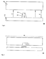
- Fig. 2 shows in a sketch 30 an exemplary second clamping sleeve 32 in a heat exchanger tube 46.
- the clamping sleeve 32 has two slotted support portions 34, 38, between which an unslotted intermediate portion 36 is provided.
- an eddy current probe 40 is arranged in the upper region of the clamping sleeve 32. By means of the eddy current probe 40, a detection of defects in the pipe wall is made possible, so that the intermediate region 36 can be placed directly over a detected defective location.
- Fig. 3 shows an exemplary anchoring claw 50 in a cross-sectional sketch.
- a clamping sleeve 52 with raised portions 54 is placed in a heat exchanger tube 58.
- the unexpanded outer diameter 56 of the clamping sleeve 52 is slightly smaller than the inner diameter 60 of the heat exchanger tube 58, so that they are easily mutually movable.
- pressure medium are provided to widen this and so enter into a positive connection with the pipe wall.
- the pressure means comprise a first 64 and a second 66 plastic tube, which are nested in each other without gaps and connect directly radially inward to the inner surface of the clamping sleeve 52.
- a radial expansion of the plastic pipes 64, 66 is transmitted directly to the clamping sleeve 52.
- a radial expansion of the plastic pipes 64, 66 or of their limited by end elements 68 and filled with water interior 70 through which a pull rod 62 extends, is achieved by a hydraulic pump 74, which is fluidically connected via a hydraulic line to the interior 70.
- Fig. 4 11 shows an exemplary portion 80 of a radial outer surface 82 of a collet extending along an axis 88.
- the outer surface 82 is interrupted by an axially extending exemplary slot 92. Extending in a direction 90 transverse to the axial extent 88 elongated raised areas 84. The non-raised areas are identified by the reference numeral 86.
- the cumulative portion of the raised areas on the radially outer surface 82 is in this case 10%.
- Fig. 5 shows in a sketch 100 an unexpanded clamping sleeve 102 under a townleyerrohrwandung 108.
- the clamping sleeve has on its radial outer surface a raised portion 104 with trapezoidal cross-section and a height 106 of 0.5 mm, for example, with respect to the non-raised area, which in turn at a distance 112th of 0.8mm from the tube wall 108 is radially spaced.
- pressure action widens the diameter of the clamping sleeve and the raised portion 104 presses form fit into the pipe wall 108th
- Fig. 6 shows in a sketch 120 a along an axis 126 extending expanded clamping sleeve with a raised portion having an axial width 124, for example, 0.3 mm, which is pressed to a depth 122 of, for example, 0.2 mm in the pipe wall.
- the design of the press-fit surfaces is such that the permissible surface pressure of the pipe is deliberately exceeded at the press-in surfaces and the pipe with its strength values still provides so much stability that it does not increase in size and yet still has the shear forces withstands the tensile load.
Landscapes
- Engineering & Computer Science (AREA)
- Mechanical Engineering (AREA)
- Chemical & Material Sciences (AREA)
- Combustion & Propulsion (AREA)
- General Engineering & Computer Science (AREA)
- Heat-Exchange Devices With Radiators And Conduit Assemblies (AREA)
- Monitoring And Testing Of Nuclear Reactors (AREA)
Priority Applications (3)
| Application Number | Priority Date | Filing Date | Title |
|---|---|---|---|
| SI201530061A SI3045262T1 (sl) | 2015-01-16 | 2015-01-16 | Sidrni parkelj za cevi prenosnika toplote |
| EP15000099.0A EP3045262B1 (fr) | 2015-01-16 | 2015-01-16 | Griffe d'ancrage pour tubes d'échangeurs thermiques |
| ES15000099.0T ES2625618T3 (es) | 2015-01-16 | 2015-01-16 | Garra de anclaje para tubos de cambiadores de calor |
Applications Claiming Priority (1)
| Application Number | Priority Date | Filing Date | Title |
|---|---|---|---|
| EP15000099.0A EP3045262B1 (fr) | 2015-01-16 | 2015-01-16 | Griffe d'ancrage pour tubes d'échangeurs thermiques |
Publications (2)
| Publication Number | Publication Date |
|---|---|
| EP3045262A1 true EP3045262A1 (fr) | 2016-07-20 |
| EP3045262B1 EP3045262B1 (fr) | 2017-03-15 |
Family
ID=52394874
Family Applications (1)
| Application Number | Title | Priority Date | Filing Date |
|---|---|---|---|
| EP15000099.0A Active EP3045262B1 (fr) | 2015-01-16 | 2015-01-16 | Griffe d'ancrage pour tubes d'échangeurs thermiques |
Country Status (3)
| Country | Link |
|---|---|
| EP (1) | EP3045262B1 (fr) |
| ES (1) | ES2625618T3 (fr) |
| SI (1) | SI3045262T1 (fr) |
Citations (4)
| Publication number | Priority date | Publication date | Assignee | Title |
|---|---|---|---|---|
| US4006930A (en) * | 1961-03-15 | 1977-02-08 | The United States Of America As Represented By The United States Energy Research And Developmnent Administration | Manipulator for hollow objects |
| US4077102A (en) * | 1976-06-28 | 1978-03-07 | Carrier Corporation | Tube extracting mechanism |
| DE4111555A1 (de) * | 1991-04-05 | 1992-10-08 | Ver Energiewerke Ag | Vorrichtung zum loesen und herausziehen von in rohrboeden befestigten rohren |
| EP0796696A1 (fr) * | 1996-03-19 | 1997-09-24 | Framatome | Procédé et dispositif d'extraction d'un tronçon de tube d'un échangeur de chaleur et utilisation du procédé et du dispositif |
-
2015
- 2015-01-16 ES ES15000099.0T patent/ES2625618T3/es active Active
- 2015-01-16 EP EP15000099.0A patent/EP3045262B1/fr active Active
- 2015-01-16 SI SI201530061A patent/SI3045262T1/sl unknown
Patent Citations (5)
| Publication number | Priority date | Publication date | Assignee | Title |
|---|---|---|---|---|
| US4006930A (en) * | 1961-03-15 | 1977-02-08 | The United States Of America As Represented By The United States Energy Research And Developmnent Administration | Manipulator for hollow objects |
| US4077102A (en) * | 1976-06-28 | 1978-03-07 | Carrier Corporation | Tube extracting mechanism |
| DE4111555A1 (de) * | 1991-04-05 | 1992-10-08 | Ver Energiewerke Ag | Vorrichtung zum loesen und herausziehen von in rohrboeden befestigten rohren |
| EP0796696A1 (fr) * | 1996-03-19 | 1997-09-24 | Framatome | Procédé et dispositif d'extraction d'un tronçon de tube d'un échangeur de chaleur et utilisation du procédé et du dispositif |
| DE69712396T2 (de) | 1996-03-19 | 2002-12-12 | Framatome Anp, Courbevoie | Verfahren und Vorrichtung zum Herausziehen eines Rohrabschnittes aus einem Wärmetauscher und Anwendung des Verfahrens und der Vorrichtung |
Also Published As
| Publication number | Publication date |
|---|---|
| SI3045262T1 (sl) | 2017-06-30 |
| ES2625618T3 (es) | 2017-07-20 |
| EP3045262B1 (fr) | 2017-03-15 |
Similar Documents
| Publication | Publication Date | Title |
|---|---|---|
| DE4041933C2 (de) | Schlauchkupplung und Verfahren zum Herstellen einer Hochdruckverbindung | |
| DE102006019405B4 (de) | Werkzeug zur Kaltexpansion von Löchern | |
| EP1959181B1 (fr) | Raccord et ensemble de connexion avec un raccord | |
| EP2957363B1 (fr) | Expandeur mecanique de tuyaux | |
| DE112012002197T5 (de) | Kopplungsstruktur für einen Kolben, der in einem Fluiddruckzylinder eingesetzt wird, und Kopplungsverfahren hierfür | |
| DE102007000550B4 (de) | Leckagedichte Anbohr-Abzweiganordnung | |
| DE602006000605T2 (de) | Klemme | |
| DE2920165A1 (de) | Vorrichtung zum abdichten zylindrischer rohre u.dgl. | |
| DE3415627A1 (de) | Rohrpruefgeraet | |
| DE69319421T2 (de) | Verfahren zum bohren von deckgebirge, verrohrungsschuh und verrohrung für diese methode und kupplungselemente für die verrohrung | |
| DE3521445A1 (de) | Hebelbolzenvorrichtung | |
| DE3716328A1 (de) | Hohlstopfen zum verschliessen eines waermetauscherrohres | |
| DE102018118779B4 (de) | Vorrichtung und Verfahren zur Verbindung zweier Bauteile mit radialem und axialem Kraftschluss | |
| DE102016123728A1 (de) | Dehnspannhülse, Werkzeughalter mit einer solchen Dehnspannhülse sowie Verfahren zum Spannen eines Werkzeugs | |
| EP3045262B1 (fr) | Griffe d'ancrage pour tubes d'échangeurs thermiques | |
| EP2050919A2 (fr) | Procédé et dispositif destiné à l'introduction d'un faisceau tubulaire constitué de tuyaux courts dans un canal de forage à l'aide d'une mesure de la force de traction | |
| EP2464908B1 (fr) | Raccord de tuyaux de gainage | |
| DE102018200267B3 (de) | Vollständig in eine Grundplatte zurückziehbare Spanndorn-Anordnung mit Niederzugeffekt | |
| DE3809369C2 (fr) | ||
| DE102007060378A1 (de) | Stopfen, insbesondere für Wärmetauscherrohre | |
| AT527527B1 (de) | Vorrichtung und Verfahren zum Beaufschlagen eines Zugelements mit einer Zugkraft | |
| DE2650371B2 (de) | Kupplungsmuffe aus Kunststoff für eine zugfeste Rohrverbindung | |
| DE102024111399B4 (de) | Verfahren zum Anschließen einer Anbohrarmatur und Anbohrarmatur | |
| DE69712396T2 (de) | Verfahren und Vorrichtung zum Herausziehen eines Rohrabschnittes aus einem Wärmetauscher und Anwendung des Verfahrens und der Vorrichtung | |
| DE2702542A1 (de) | Waermerueckstellbare, hohle metallische kupplung |
Legal Events
| Date | Code | Title | Description |
|---|---|---|---|
| PUAI | Public reference made under article 153(3) epc to a published international application that has entered the european phase |
Free format text: ORIGINAL CODE: 0009012 |
|
| AK | Designated contracting states |
Kind code of ref document: A1 Designated state(s): AL AT BE BG CH CY CZ DE DK EE ES FI FR GB GR HR HU IE IS IT LI LT LU LV MC MK MT NL NO PL PT RO RS SE SI SK SM TR |
|
| AX | Request for extension of the european patent |
Extension state: BA ME |
|
| 17P | Request for examination filed |
Effective date: 20160913 |
|
| GRAP | Despatch of communication of intention to grant a patent |
Free format text: ORIGINAL CODE: EPIDOSNIGR1 |
|
| GRAS | Grant fee paid |
Free format text: ORIGINAL CODE: EPIDOSNIGR3 |
|
| RIC1 | Information provided on ipc code assigned before grant |
Ipc: B23P 19/02 20060101AFI20161128BHEP Ipc: B25B 27/06 20060101ALI20161128BHEP Ipc: F28F 11/00 20060101ALI20161128BHEP Ipc: F22B 37/58 20060101ALI20161128BHEP Ipc: F22B 37/00 20060101ALI20161128BHEP Ipc: B25B 5/06 20060101ALI20161128BHEP |
|
| INTG | Intention to grant announced |
Effective date: 20161215 |
|
| GRAA | (expected) grant |
Free format text: ORIGINAL CODE: 0009210 |
|
| AK | Designated contracting states |
Kind code of ref document: B1 Designated state(s): AL AT BE BG CH CY CZ DE DK EE ES FI FR GB GR HR HU IE IS IT LI LT LU LV MC MK MT NL NO PL PT RO RS SE SI SK SM TR |
|
| REG | Reference to a national code |
Ref country code: CH Ref legal event code: EP Ref country code: GB Ref legal event code: FG4D Free format text: NOT ENGLISH |
|
| REG | Reference to a national code |
Ref country code: IE Ref legal event code: FG4D Free format text: LANGUAGE OF EP DOCUMENT: GERMAN |
|
| REG | Reference to a national code |
Ref country code: AT Ref legal event code: REF Ref document number: 875054 Country of ref document: AT Kind code of ref document: T Effective date: 20170415 |
|
| REG | Reference to a national code |
Ref country code: DE Ref legal event code: R096 Ref document number: 502015000688 Country of ref document: DE |
|
| REG | Reference to a national code |
Ref country code: SE Ref legal event code: TRGR |
|
| REG | Reference to a national code |
Ref country code: NL Ref legal event code: MP Effective date: 20170315 |
|
| REG | Reference to a national code |
Ref country code: ES Ref legal event code: FG2A Ref document number: 2625618 Country of ref document: ES Kind code of ref document: T3 Effective date: 20170720 |
|
| REG | Reference to a national code |
Ref country code: LT Ref legal event code: MG4D |
|
| PG25 | Lapsed in a contracting state [announced via postgrant information from national office to epo] |
Ref country code: GR Free format text: LAPSE BECAUSE OF FAILURE TO SUBMIT A TRANSLATION OF THE DESCRIPTION OR TO PAY THE FEE WITHIN THE PRESCRIBED TIME-LIMIT Effective date: 20170616 Ref country code: LT Free format text: LAPSE BECAUSE OF FAILURE TO SUBMIT A TRANSLATION OF THE DESCRIPTION OR TO PAY THE FEE WITHIN THE PRESCRIBED TIME-LIMIT Effective date: 20170315 Ref country code: HR Free format text: LAPSE BECAUSE OF FAILURE TO SUBMIT A TRANSLATION OF THE DESCRIPTION OR TO PAY THE FEE WITHIN THE PRESCRIBED TIME-LIMIT Effective date: 20170315 Ref country code: FI Free format text: LAPSE BECAUSE OF FAILURE TO SUBMIT A TRANSLATION OF THE DESCRIPTION OR TO PAY THE FEE WITHIN THE PRESCRIBED TIME-LIMIT Effective date: 20170315 Ref country code: NO Free format text: LAPSE BECAUSE OF FAILURE TO SUBMIT A TRANSLATION OF THE DESCRIPTION OR TO PAY THE FEE WITHIN THE PRESCRIBED TIME-LIMIT Effective date: 20170615 |
|
| PG25 | Lapsed in a contracting state [announced via postgrant information from national office to epo] |
Ref country code: BG Free format text: LAPSE BECAUSE OF FAILURE TO SUBMIT A TRANSLATION OF THE DESCRIPTION OR TO PAY THE FEE WITHIN THE PRESCRIBED TIME-LIMIT Effective date: 20170615 Ref country code: RS Free format text: LAPSE BECAUSE OF FAILURE TO SUBMIT A TRANSLATION OF THE DESCRIPTION OR TO PAY THE FEE WITHIN THE PRESCRIBED TIME-LIMIT Effective date: 20170315 Ref country code: LV Free format text: LAPSE BECAUSE OF FAILURE TO SUBMIT A TRANSLATION OF THE DESCRIPTION OR TO PAY THE FEE WITHIN THE PRESCRIBED TIME-LIMIT Effective date: 20170315 |
|
| PG25 | Lapsed in a contracting state [announced via postgrant information from national office to epo] |
Ref country code: NL Free format text: LAPSE BECAUSE OF FAILURE TO SUBMIT A TRANSLATION OF THE DESCRIPTION OR TO PAY THE FEE WITHIN THE PRESCRIBED TIME-LIMIT Effective date: 20170315 |
|
| PG25 | Lapsed in a contracting state [announced via postgrant information from national office to epo] |
Ref country code: RO Free format text: LAPSE BECAUSE OF FAILURE TO SUBMIT A TRANSLATION OF THE DESCRIPTION OR TO PAY THE FEE WITHIN THE PRESCRIBED TIME-LIMIT Effective date: 20170315 Ref country code: EE Free format text: LAPSE BECAUSE OF FAILURE TO SUBMIT A TRANSLATION OF THE DESCRIPTION OR TO PAY THE FEE WITHIN THE PRESCRIBED TIME-LIMIT Effective date: 20170315 Ref country code: SK Free format text: LAPSE BECAUSE OF FAILURE TO SUBMIT A TRANSLATION OF THE DESCRIPTION OR TO PAY THE FEE WITHIN THE PRESCRIBED TIME-LIMIT Effective date: 20170315 Ref country code: CZ Free format text: LAPSE BECAUSE OF FAILURE TO SUBMIT A TRANSLATION OF THE DESCRIPTION OR TO PAY THE FEE WITHIN THE PRESCRIBED TIME-LIMIT Effective date: 20170315 |
|
| PG25 | Lapsed in a contracting state [announced via postgrant information from national office to epo] |
Ref country code: IS Free format text: LAPSE BECAUSE OF FAILURE TO SUBMIT A TRANSLATION OF THE DESCRIPTION OR TO PAY THE FEE WITHIN THE PRESCRIBED TIME-LIMIT Effective date: 20170715 Ref country code: PT Free format text: LAPSE BECAUSE OF FAILURE TO SUBMIT A TRANSLATION OF THE DESCRIPTION OR TO PAY THE FEE WITHIN THE PRESCRIBED TIME-LIMIT Effective date: 20170717 Ref country code: PL Free format text: LAPSE BECAUSE OF FAILURE TO SUBMIT A TRANSLATION OF THE DESCRIPTION OR TO PAY THE FEE WITHIN THE PRESCRIBED TIME-LIMIT Effective date: 20170315 Ref country code: SM Free format text: LAPSE BECAUSE OF FAILURE TO SUBMIT A TRANSLATION OF THE DESCRIPTION OR TO PAY THE FEE WITHIN THE PRESCRIBED TIME-LIMIT Effective date: 20170315 |
|
| REG | Reference to a national code |
Ref country code: DE Ref legal event code: R097 Ref document number: 502015000688 Country of ref document: DE |
|
| PLBE | No opposition filed within time limit |
Free format text: ORIGINAL CODE: 0009261 |
|
| REG | Reference to a national code |
Ref country code: FR Ref legal event code: PLFP Year of fee payment: 4 |
|
| STAA | Information on the status of an ep patent application or granted ep patent |
Free format text: STATUS: NO OPPOSITION FILED WITHIN TIME LIMIT |
|
| PG25 | Lapsed in a contracting state [announced via postgrant information from national office to epo] |
Ref country code: DK Free format text: LAPSE BECAUSE OF FAILURE TO SUBMIT A TRANSLATION OF THE DESCRIPTION OR TO PAY THE FEE WITHIN THE PRESCRIBED TIME-LIMIT Effective date: 20170315 |
|
| 26N | No opposition filed |
Effective date: 20171218 |
|
| PG25 | Lapsed in a contracting state [announced via postgrant information from national office to epo] |
Ref country code: IT Free format text: LAPSE BECAUSE OF FAILURE TO SUBMIT A TRANSLATION OF THE DESCRIPTION OR TO PAY THE FEE WITHIN THE PRESCRIBED TIME-LIMIT Effective date: 20170315 |
|
| PG25 | Lapsed in a contracting state [announced via postgrant information from national office to epo] |
Ref country code: MT Free format text: LAPSE BECAUSE OF FAILURE TO SUBMIT A TRANSLATION OF THE DESCRIPTION OR TO PAY THE FEE WITHIN THE PRESCRIBED TIME-LIMIT Effective date: 20170315 |
|
| PG25 | Lapsed in a contracting state [announced via postgrant information from national office to epo] |
Ref country code: LU Free format text: LAPSE BECAUSE OF NON-PAYMENT OF DUE FEES Effective date: 20180116 |
|
| REG | Reference to a national code |
Ref country code: IE Ref legal event code: MM4A |
|
| PG25 | Lapsed in a contracting state [announced via postgrant information from national office to epo] |
Ref country code: IE Free format text: LAPSE BECAUSE OF NON-PAYMENT OF DUE FEES Effective date: 20180116 |
|
| PG25 | Lapsed in a contracting state [announced via postgrant information from national office to epo] |
Ref country code: MC Free format text: LAPSE BECAUSE OF FAILURE TO SUBMIT A TRANSLATION OF THE DESCRIPTION OR TO PAY THE FEE WITHIN THE PRESCRIBED TIME-LIMIT Effective date: 20170315 |
|
| PG25 | Lapsed in a contracting state [announced via postgrant information from national office to epo] |
Ref country code: TR Free format text: LAPSE BECAUSE OF FAILURE TO SUBMIT A TRANSLATION OF THE DESCRIPTION OR TO PAY THE FEE WITHIN THE PRESCRIBED TIME-LIMIT Effective date: 20170315 |
|
| PG25 | Lapsed in a contracting state [announced via postgrant information from national office to epo] |
Ref country code: HU Free format text: LAPSE BECAUSE OF FAILURE TO SUBMIT A TRANSLATION OF THE DESCRIPTION OR TO PAY THE FEE WITHIN THE PRESCRIBED TIME-LIMIT; INVALID AB INITIO Effective date: 20150116 Ref country code: CY Free format text: LAPSE BECAUSE OF FAILURE TO SUBMIT A TRANSLATION OF THE DESCRIPTION OR TO PAY THE FEE WITHIN THE PRESCRIBED TIME-LIMIT Effective date: 20170315 Ref country code: MK Free format text: LAPSE BECAUSE OF NON-PAYMENT OF DUE FEES Effective date: 20170315 |
|
| PG25 | Lapsed in a contracting state [announced via postgrant information from national office to epo] |
Ref country code: AL Free format text: LAPSE BECAUSE OF FAILURE TO SUBMIT A TRANSLATION OF THE DESCRIPTION OR TO PAY THE FEE WITHIN THE PRESCRIBED TIME-LIMIT Effective date: 20170315 |
|
| REG | Reference to a national code |
Ref country code: AT Ref legal event code: MM01 Ref document number: 875054 Country of ref document: AT Kind code of ref document: T Effective date: 20200116 |
|
| PG25 | Lapsed in a contracting state [announced via postgrant information from national office to epo] |
Ref country code: AT Free format text: LAPSE BECAUSE OF NON-PAYMENT OF DUE FEES Effective date: 20200116 |
|
| PGFP | Annual fee paid to national office [announced via postgrant information from national office to epo] |
Ref country code: SI Payment date: 20251224 Year of fee payment: 12 |
|
| REG | Reference to a national code |
Ref country code: CH Ref legal event code: U11 Free format text: ST27 STATUS EVENT CODE: U-0-0-U10-U11 (AS PROVIDED BY THE NATIONAL OFFICE) Effective date: 20260201 |
|
| PGFP | Annual fee paid to national office [announced via postgrant information from national office to epo] |
Ref country code: SE Payment date: 20260121 Year of fee payment: 12 |
|
| PGFP | Annual fee paid to national office [announced via postgrant information from national office to epo] |
Ref country code: GB Payment date: 20260127 Year of fee payment: 12 |
|
| PGFP | Annual fee paid to national office [announced via postgrant information from national office to epo] |
Ref country code: ES Payment date: 20260218 Year of fee payment: 12 |
|
| PGFP | Annual fee paid to national office [announced via postgrant information from national office to epo] |
Ref country code: DE Payment date: 20251211 Year of fee payment: 12 |
|
| PGFP | Annual fee paid to national office [announced via postgrant information from national office to epo] |
Ref country code: BE Payment date: 20260113 Year of fee payment: 12 |
|
| PGFP | Annual fee paid to national office [announced via postgrant information from national office to epo] |
Ref country code: FR Payment date: 20260121 Year of fee payment: 12 |
|
| PGFP | Annual fee paid to national office [announced via postgrant information from national office to epo] |
Ref country code: CH Payment date: 20260201 Year of fee payment: 12 |